
OWNER’S MANUAL
Electric Vehicle Charger
Read the “Important Safety Instructions” before use to ensure safe operation.
After reading the user manual, store it in an accessible place for easy reference.
www.lg.com
Copyright © 2024 LG Electronics Inc. All Rights Reserved.
Printed in Korea
EVW011SK-SN
EVW011SK-SR
EVW011SK-SH
EVW011SK-SD
EVW011SK-SO
EVW011SK-SL
EVW011SK-SA
EVW011SK-SX
*MFL72095901*
(2407-REV07)

2
ENGLISH
TABLE OF CONTENTS
PRE-CHECK INFORMATION ......3
- SIGNS ON THE EVSE ................................................ 3
IMPORTANT SAFETY
INSTRUCTIONS ..........................4
MOVING AND STORAGE
INSTRUCTIONS ..........................7
- Storage .............................................................................7
- Transportation and Delivery .................................. 7
CHARGER SPECIFICATIONS ...... 8
ACCESSORIES.............................9
MECHANICAL
CHARACTERISTICS ................. 10
- Charger Size ................................................................10
- Charger Appearance ...............................................11
INSTALLATION
INSTRUCTIONS ....................... 12
- Installation Location ...............................................12
- Installation Guide ....................................................13
- Wiring and Grounding ........................................... 15
- Electrical Network type ........................................17
OPERATING
INSTRUCTIONS ....................... 18
- Charging Precautions .............................................18
- Charging Operation Procedure ......................... 19
- Common Screen Configuration ........................20
- Charging Process......................................................22
- Error Screen ................................................................ 27
- Error Recovery Screen ...........................................27
- Operation Stop (Availability Change)
Screen ............................................................................28
- Firmware Download Screen ...............................28
- Setting Screen ........................................................... 29
FAULT CODES .......................... 30
CERTIFICATION ....................... 31
Open Source Software Notice Information
To obtain the source code under GPL, LGPL, MPL, and
other open source licenses that have the obligations
to disclose source code, that is contained in this
product, and to access all referred license terms,
copyright notices and other relevant documents please
visit
https://opensource.lge.com
.
LG Electronics will also provide open source code to
you on CD-ROM for a charge covering the cost of
performing such distribution (such as the cost of
media, shipping, and handling) upon email request
to
opensourc[email protected]
.
This offer is valid to anyone in receipt of this
information for a period of three yearsafter our last
shipment of this product.
LG Take-back & Recycling Policy
(For USA)
LG Electronics offers a customized e-waste take-
back & recycling service that meets local needs
and requirements in the countries where e-waste
regulations are in place, and also provides product take-
back & recycling service voluntarily in some regions.
LG Electronics evaluates product’s recyclability at the
design step selectively, with the goal of improving
recyclability where practicable. Through these activities,
LG Electronics seeks to contribute to conserving natural
resources and protecting the environment. For more
information, please visit our global site at
http://www.
lg.com/recycling
3
ENGLISH
PRE-CHECK INFORMATION
• The information provided in this document includes general descriptions or technical characteristics of the included
product.
• This document is not intended to be used or replaced for specific users who wish to determine the suitability or
reliability of this product.
• Users or those responsible for this product need to know correct usage and perform risk assessment in advance, and
evaluation and testing related to specific applications or use of the product are required.
• Please inform us if there are errors or modifications needed in this document.
• To install and use this product, safety regulations of the relevant country and region must be strictly complied with.
• For safety reasons and compliance with documented system data, only the manufacturer is obliged to repair parts.
Proper training is necessary to use the product in accordance with technical safety requirements.
• Failure to use the software of our hardware products accurately can lead to injuries, damage, or operational errors.
SIGNS ON THE EVSE
• Please read the manual carefully before installation, operation, and maintenance of the product. The following
messages will appear throughout the document to warn of potential dangers or provide information for explaining
procedures.
This is a safety prevention symbol.
Caution: If these safety precautions are not followed, injuries or damage can occur.
Hazard signs relate to high voltage matters.
If the safety rules and instructions in this manual are not adhered to, death or serious injury
could occur due to electric shock and burns.

4
ENGLISH
IMPORTANT SAFETY INSTRUCTIONS
WARNING
This manual contains important instructions for Models EVW011SK-SN, EVW011SK-SR, EVW011SK-SH,
EVW011SK-SD, EVW011SK-SO, EVW011SK-SL, EVW011SK-SA, EVW011SK-SX that shall be followed during
installation, operation and maintenance of the unit.
1 Read all the instructions before using this product.
2 This device should be supervised when used around children.
3 Do not put fingers into the electric vehicle connector.
4 Do not use this product if the flexible power cord or EV cable is frayed, has broken insulation, or any other signs of
damage
5 Do not use this product if the enclosure or the EV connector is broken, cracked, open, or shows any other indication
of damage.
6 First, read this: This document includes important safety information. Before repairing or performing any
maintenance in case of malfunction, read the entire manual first.
7 Qualified personnel: The charger must be installed, disassembled, or inspected by an electrician in accordance
with the electrical regulations of the relevant area. The information in this manual does not alleviate the reader's
responsibility for local safety regulations and standard regulations.
8 Electric shock accident: There can be a potential risk of fatal electric shock accidents. Inspection of the product's
interior must be performed exclusively by a certified electrician.
9 Do not modify.: Do not arbitrarily modify the charger. Doing so will void the warranty period and could result in a
fatal electric shock or fire.

5
ENGLISH
INSTRUCTIONS PERTAINING TO A RISK OF FIRE OR ELECTRIC SHOCK
• To prevent the risk of fire or electric shock accidents, please read and follow these safety precautions and operating
procedures carefully.
• There is a risk of electric shock. Do not connect the electric vehicle and the charger before the inspection. Just turning
off the charger does not reduce the risk.
• Do not touch the non-insulated parts of the output connector. There could be a serious risk of electric shock.
• Do not use a connector with exposed damaged wires or a damaged connector. Replace all damaged parts with new
ones before operation.
• Do not disassemble the charger. Have it inspected by a certified technician. Incorrect assembly can cause an explosion,
electric shock, or fire.
• Never use the charger if the vehicle's inlet or charger connector is wet.
• Do not install or operate with wet hands. There is a risk of electric shock.
• Disconnect the input power before opening the charger case. Contact with electrically live parts of the charger can
lead to electric shock accidents, serious injuries, or even death.
• Perform grounding work according to national electrical safety standards and local electrical safety standards. Not
grounding properly can lead to fatal electric shock accidents.

6
ENGLISH
CAUTION
• Ensure the charger connector is free from water, humidity, or foreign substances.
• Do not place the charger near flammable materials during use. Keep it away from carpets and cluttered workspaces.
• Educate children to prevent them from playing with the device.
• Users are responsible for adhering to national and local electrical safety standards in the area where the device is
installed.
• Do not connect or disconnect the connector while charging. Doing so damages the connector, and may damage the
charger or cause the battery to explode.
• Do not operate the charger with the panel removed or the door open.
• If the charger is dropped, suffered a severe shock or any other type of damage, do not operate it. Call a service
manager.
• In dusty environments, more frequent maintenance is required for maximum device lifespan and optimal performance.
• Do not use the charger during heavy rain or lightning.
• Electric shock accident: There is a risk of electric shock. Hazardous electrical energy is stored in the capacitor. Even if
the electric supply to the charger is cut off, do not open the charger case for at least 5 minutes after disconnection.
• Ensure that the power supply to the charger is off before proceeding with charger maintenance procedures.
• To reduce the risk of fire, connect only to a circuit provided with 60 amperes maximum branch circuit overcurrent
protection in accordance with the the applicable National Installation Codes in Annex A, Ref. 1 .
• Do not use this product if there is any damage to the unit.
WARNING
• GROUNDING INSTRUCTIONS : This product must be connected to a grounded, metal, permanent wiring system, or an
equipment grounding conductor must be run with the circuit conductors and connected to the equipment grounding
terminal or lead on the product
• SAVE THESE INSTRUCTIONS

7
ENGLISH
MOVING AND STORAGE INSTRUCTIONS
EVW011SK-SN, EVW011SK-SR, EVW011SK-SH, EVW011SK-SD,
EVW011SK-SO, EVW011SK-SL, EVW011SK-SA, EVW011SK-SX
For maximum performance, please read the following instructions.
Storage
Before installing and powering the charger, ensure that the product is stored in a clean and dry environment at a
temperature of -40°C to 70°C (-40°F to 158°F). The charger must always be stored upright in a box during cargo
loading. This protects the charger from dust and scratches. The charger must be stored in a protected location to avoid
damage. Do not stack other items on top of it.
Transportation and Delivery
• Check the product box for any damage.
• After opening the box, confirm there are no damage or abnormalities in the product's appearance.
• When transporting the product, keep the cover locked. Causing shocks or dropping the product during transportation
can result in product damage.
• The device is not to be lifted or carried by either the flexible cord or the EV cable.
• Please keep the original packaging for service return in future. All Products must be sent in secured packaging to
avoid any shipping damages. LG is not responsible for the shipping damages.
8
ENGLISH
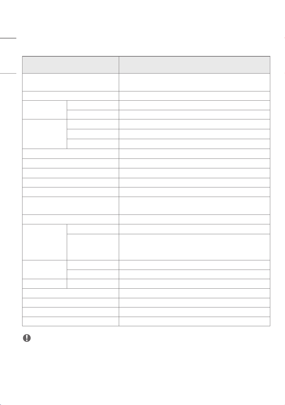
CHARGER SPECIFICATIONS
Model
EVW011SK-SN, EVW011SK-SR, EVW011SK-SH, EVW011SK-SD,
EVW011SK-SO, EVW011SK-SL, EVW011SK-SA, EVW011SK-SX
Size (Width x Height x Depth)
226mm x 503mm x 165mm
(8.89inches x 19.8inches x 6.49inches)
Weight 7.1kg (15.6lbs)
AC Input
Voltage Single Phase (208 / 240V ± 10%)
Frequency 60Hz
AC Output
Voltage Single Phase (208 / 240V ± 10%)
Current 48A
Capacity 11.5kW
IP Rating IP55, TYPE 3R / NEMA3R
Operating Temperature -35°C ~ 50°C (-31°F to 122°F)
Operating Humidity < Rh95% (Non-condensing conditions)
Storage Temperature -40°C ~ 70°C(-40°F to 158°F)
Storage Humidity < Rh95% (Non-condensing conditions)
Protection Features
Overcurrent/Overvoltage Protection,
Circuit Breaker in case of Leakage/Ground Fault Detection
User Authentication RFID Card Reader
Display Device
7dit 14Segmet Charged Amount / Elapsed Time / Fault Details / Charge Status
Charge Status
Indicator LED
Standby: Blue /
Charging: Green flow / Fully Charged: Blinking Green /
Error: Blinking Red / Wait: Flow of blue, light blue, green
Charge Type
Format UL2594 / Type : C
Connector SAE J1772 (5PIN)
Voice Guidance
Speaker
2)
Audio output (5W)
Certification UL Certified, Bluetooth SIG Certified
Wireless LAN IEEE 802.11a/b/g/n/ac
Bluetooth Low Energy 5.3
Recommended Mobile Monthly Data Usage A minimum of 140 MB or more
1)
NOTE
•
1)
Subject to changes depending on the operating company’s environment and policy.
•
2)
Speaker Maximum Power : 5.0W, white noise for 1minute.
9
ENGLISH
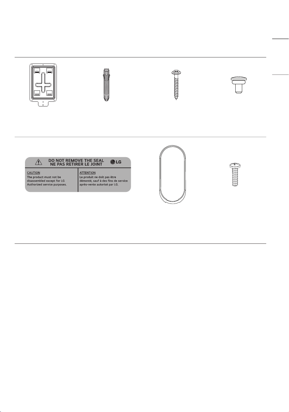
ACCESSORIES
Wall Mount
1 piece
Wall Mount Fixing Anchor
2 piece
Wall Mount Fixing Screw
2 piece
M4 O-ring Screw
1 piece
SEAL LABEL
2 piece
Body Deco
1 piece
Front Body and Main
Body Joint Screw
3 piece
(a spare portion)
10
ENGLISH
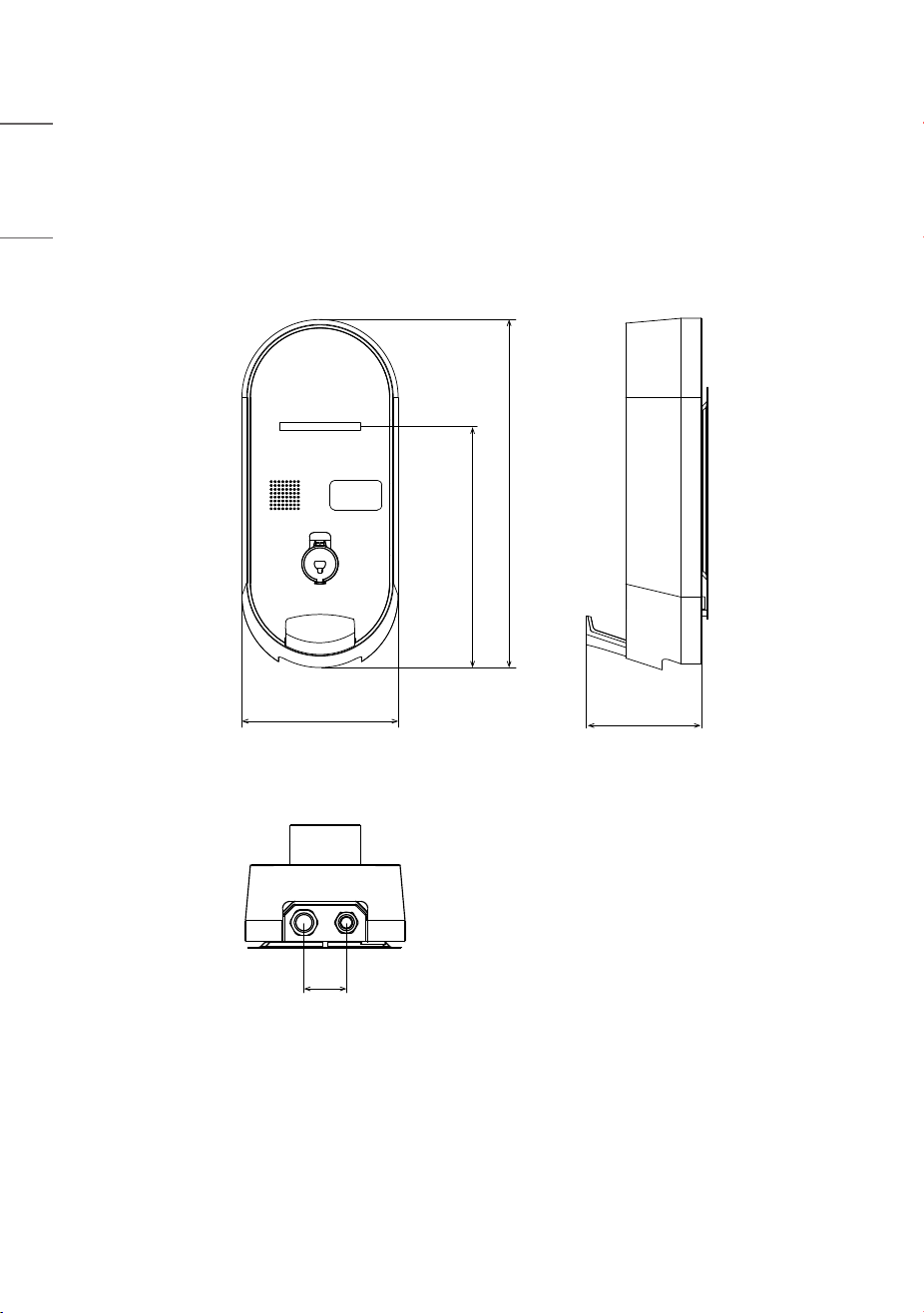
MECHANICAL CHARACTERISTICS
Charger Size
[Unit : mm (inches)]
226(8.89)
60
(2.3)
165(6.49)
348.4(13.7)
503.2(19.8)
11
ENGLISH
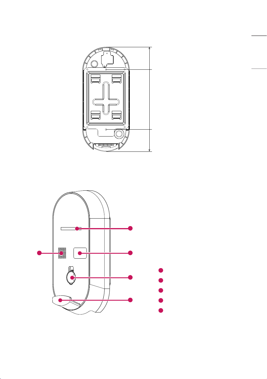
[Unit : mm (inches)]
105.4(4.1)
290(11.4)
107.8(4.2)
Charger Appearance
1
3
4
2
5
1
7-dit 14Segment
2
RFID Card Reader
3
Connector (AC 5-pin) Holder
4
Cable Holder
5
Speaker

12
ENGLISH
INSTALLATION INSTRUCTIONS
Caution!
• Do not expose the charger to rain, high temperatures, dust, corrosive gases, flammable
substances, or explosive gases.
Installation Location
WARNING
Risk of explosion. This equipment has arcing or sparking parts that should not be exposed to flammable vapors. This
equipment should be located at least 460mm (18.1inches) above the floor.
1) When the device installed outdoor
This device shall be mounted at a sufficient height from grade such that the height of the storage means for the
coupling device is located between 600mm (23.6inches) and 1.2m (3.9feets) from grade.
2) When the device installed indoor
This device shall be mounted at a sufficient height from grade such that the height of the storage means for the
coupling device is located between 450mm (17.7inches) and 1.2m (3.9feets) from grade.
• For optimal performance and maximum lifespan, choose your installation location carefully. Operational lifespan and
performance are affected by the location of the charger.
• Choose a dry area with good ventilation.
• To reduce the risk of fire, install the charger on a non-combustible surface made of concrete, stone, brick, or iron.
• Do not block the front of the charger.
• Install the charger at a height of 0.6 to 1.2 m (1.9-3.9feets)above the ground.
• Install in a location equipped with an earth leakage circuit breaker.
• Do not expose the charger to rain, high temperatures, dust, corrosive gases, flammable substances, or explosive
gases.
• Install a certain distance from the parking space to prevent damage from parked vehicles.
13
ENGLISH
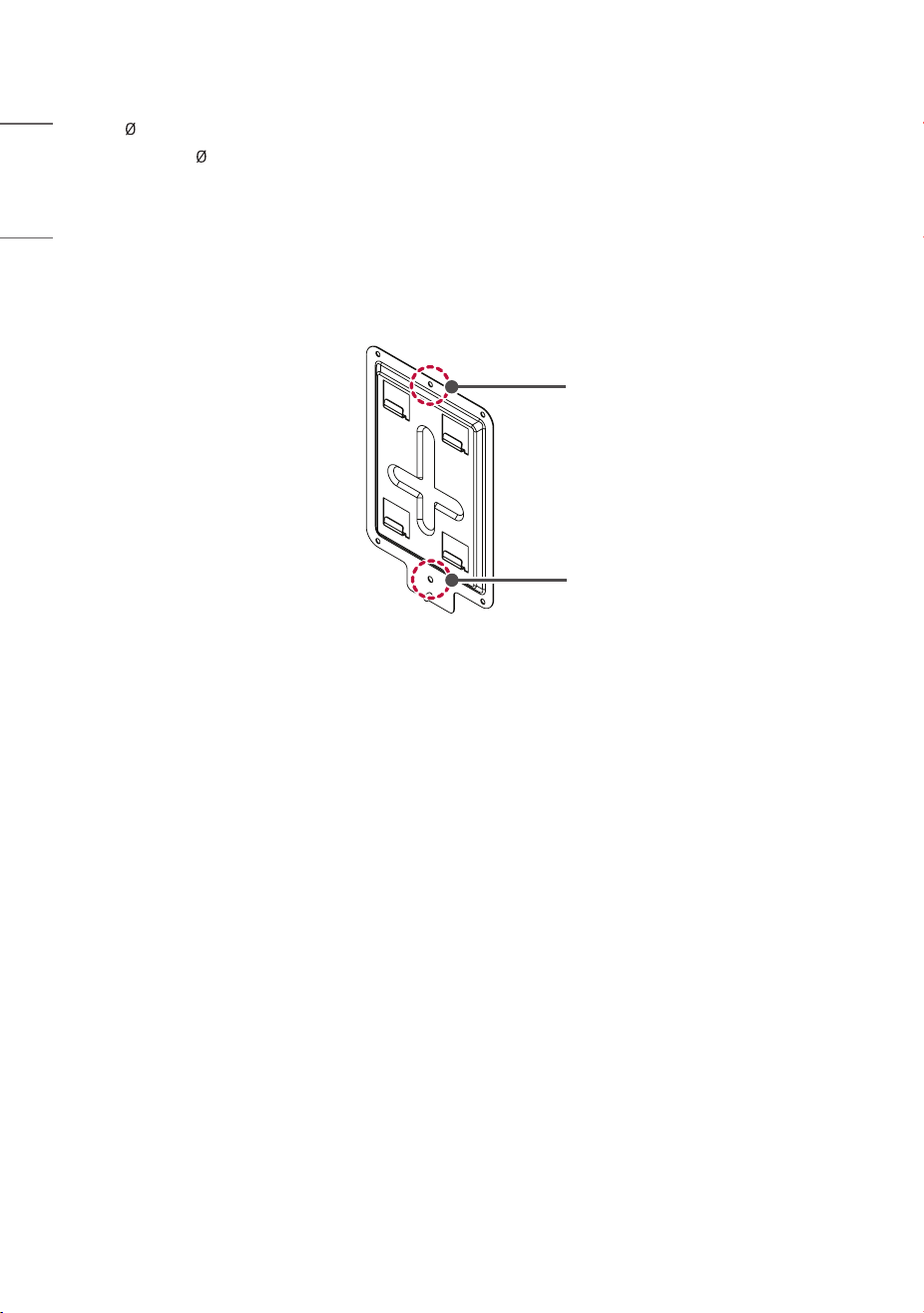
Installation Guide
Installation Process_Charger
• Use the enclosed fixing anchors and screws to hang the wall mount on the wall.
- Check the wall material and thickness of the finishing materials.
- The enclosed anchors and screws can be used when the wall material is non-cracking concrete, lightweight concrete,
strong natural stone, soft natural stone, brick, and hollow block.
- Never install on walls made of plasterboard or material made by compressing paper/wood dust (MDF). If you must
install, anchor screws must be fixed into the retaining wall (concrete) within the finishing materials. If there is no
retaining wall, an additional hanger must be installed before fixing the anchor screws.
- If installing on other unspecified wall materials, ensure the material can withstand a pull-out load of 70kgf (686N)
and a shearing load of 100kgf (980N) per anchor point.
Wall-mounted Device Fixing Screw
Anchor
a
d
b
e
c
14
ENGLISH
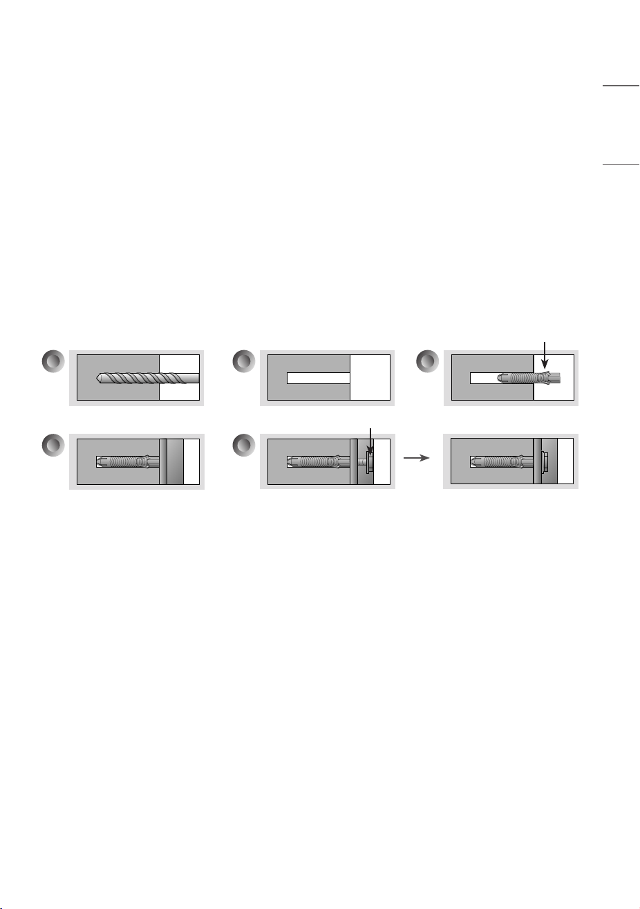
- Use a 8 mm drill bit for concrete and a hammer (impact) drill.
a. Use a drill bit of 8 mm to drill holes to a depth of 80mm - 100mm (3.1-3.9inches) at the anchor positions.
b. Clean the drilled holes.
c. Insert the enclosed anchor into the hole (use a hammer when inserting the anchor).
d. Press the wall mount against the wall in alignment with the hole positions. Ensure the angle adjustment part faces
upward.
e. Align the wall mount fixing screws with the holes and fasten them. At this point, tighten the screws to a torque of
45 kgf/cm - 60 kgf/cm (441-588N) or more.
Fixing Screw
Fixing Screw
15
ENGLISH
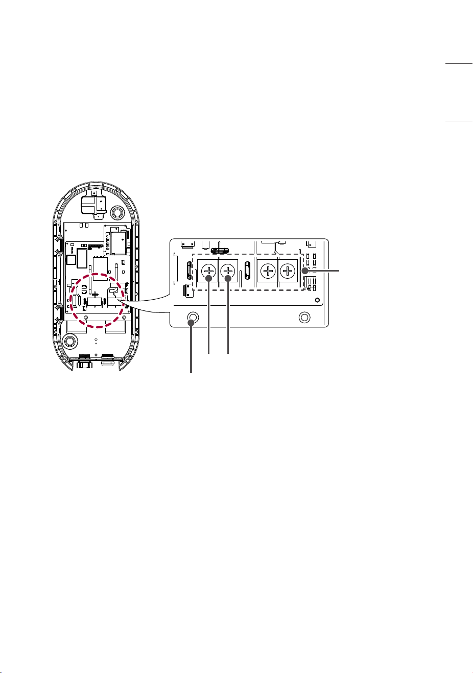
Wiring and Grounding
1 Check that the breaker on the distribution panel is turned off.
2 Detach the plastic cover on the terminal block.
3 Insert the AC 208 / 240V input cable through the power cable input at the bottom.
4 Connect the AC 208 / 240V input cable to the left power connection terminal and the internal panel GND terminal
on the terminal block.
5 Reattach the plastic cover on the terminal block.
Terminal Block
GND
L1
L2
16
ENGLISH
NOTE
• The AC input power cable is not included with the charger.
• The cable specifications should be determined based on the distance between the distribution panel and the charger,
according to the conditions of the installation work.
• The disconnect switch should be installed inside the distribution panel of the installation location.
• The cross-sectional area of the input line/ground line should be at least 6 AWG.
• Field Wiring Terminal : Use Copper Conductors Only. (Temperature rating : 90 °C (194 °F))
• Pressure terminal Connector.
Parameter Specifications
Wire Size for the terminal block plug 6AWG
Stud Size for the terminal block plug 6 mm (0.2 inches)
Material Oxygen Free Copper
Manufacturer Jeono
Type JOR-16-6
Shape R-Shape
Required Torque 26 lbf*In / 29.9 kgf*cm
17
ENGLISH
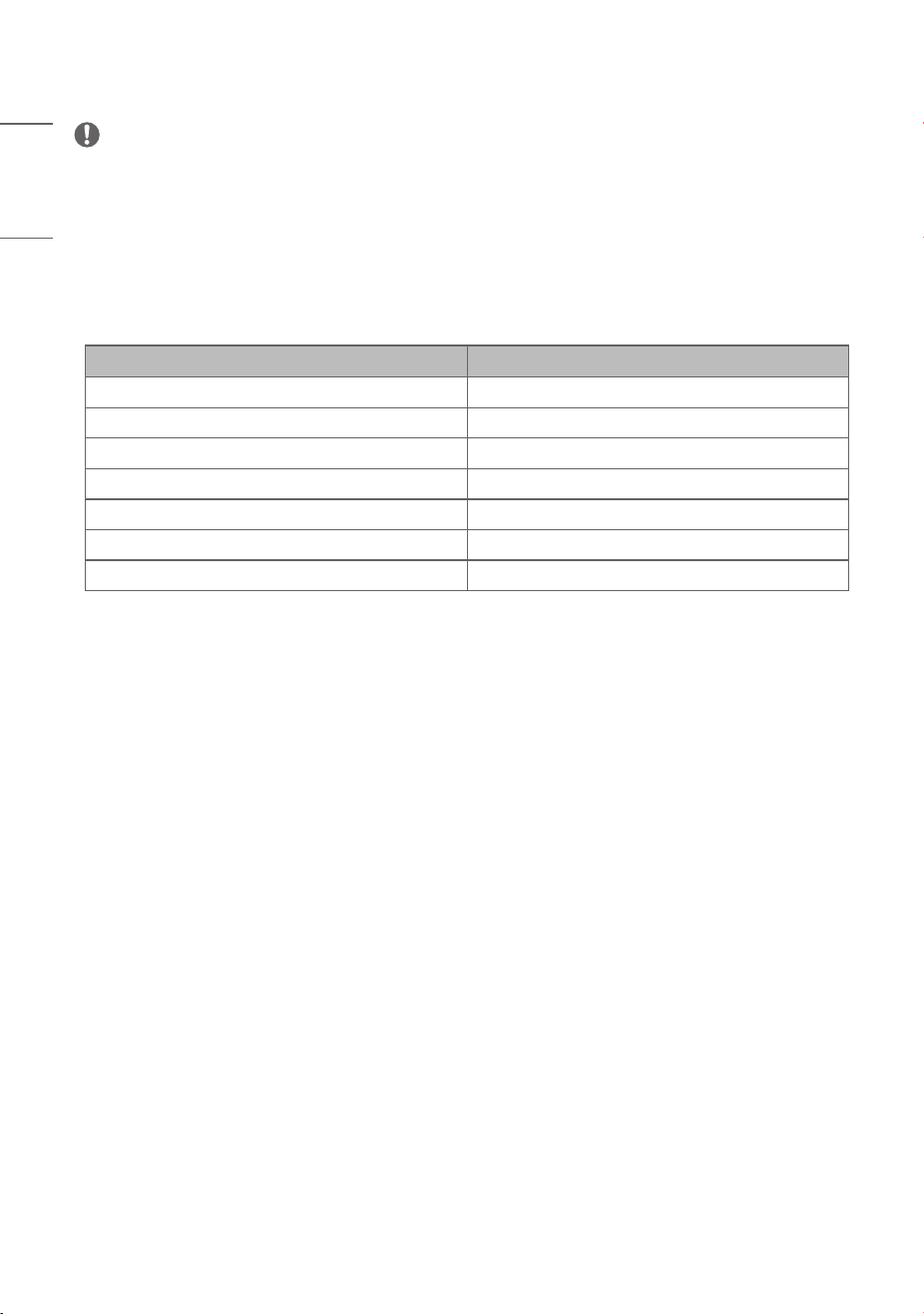
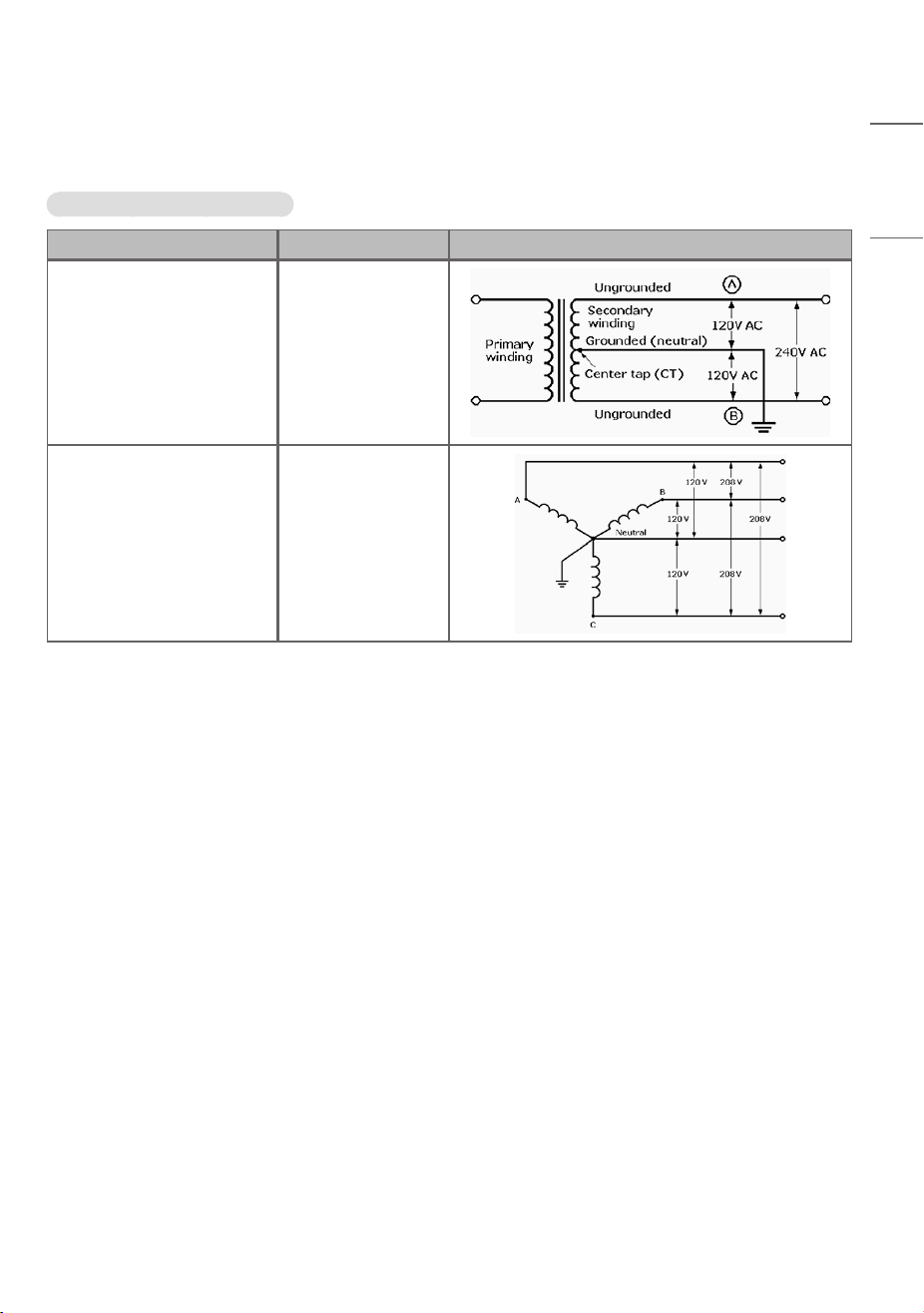
Electrical Network type
Available Electrical network type
Electrical network type Voltage Picture
Split Phase 216Vac ~ 264Vac
WYE Network 187Vac ~ 228Vac

18
ENGLISH
OPERATING INSTRUCTIONS
Caution!
To prevent electric shock, do not touch uninsulated parts of the connector or the internal
terminals of the charger. Do not use the connector if there are damaged or corroded
parts. Using a damaged or defective connector can lead to overheating or the risk of
electric shock.
Charging Precautions
Please check that installation has been completed in the order specified in this manual. Failure to do so can result in
personal injury or damage to the charger.
19
ENGLISH
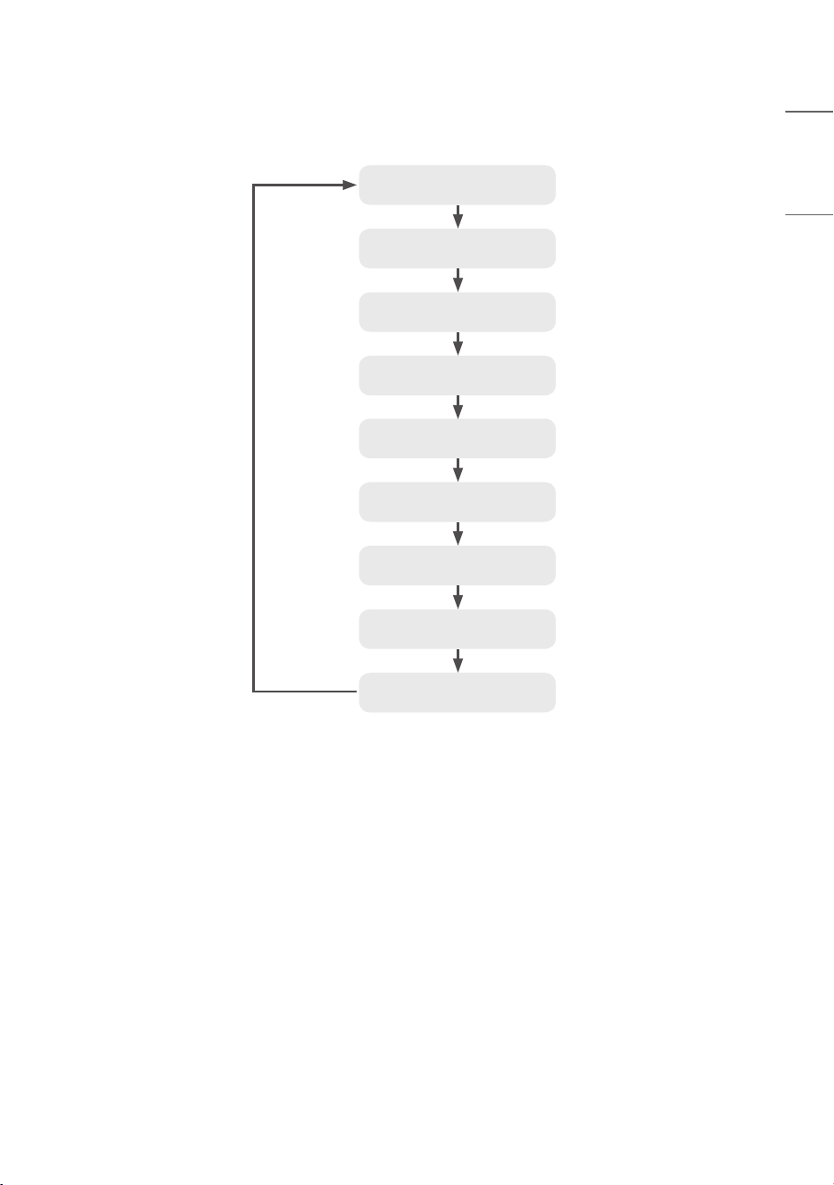
Charging Operation Procedure
Ready for charging
(Connector automatic lock on*)
Charging standby screen
Authentication and payment
Electric vehicle connector
connection
Start charging
Stop charging
(Connector automatic lock off*)
Charging complete/stop
Connector clean-up
• *: The automatic lock/release of the connector is controlled by the vehicle (whether this is supported varies
depending on the model of the vehicle)
• The charging speed may vary depending on the characteristics of the vehicle model and the condition of the battery.
• For safety, refer to “IMPORTANT SAFETY INSTRUCTIONS”.
20
ENGLISH
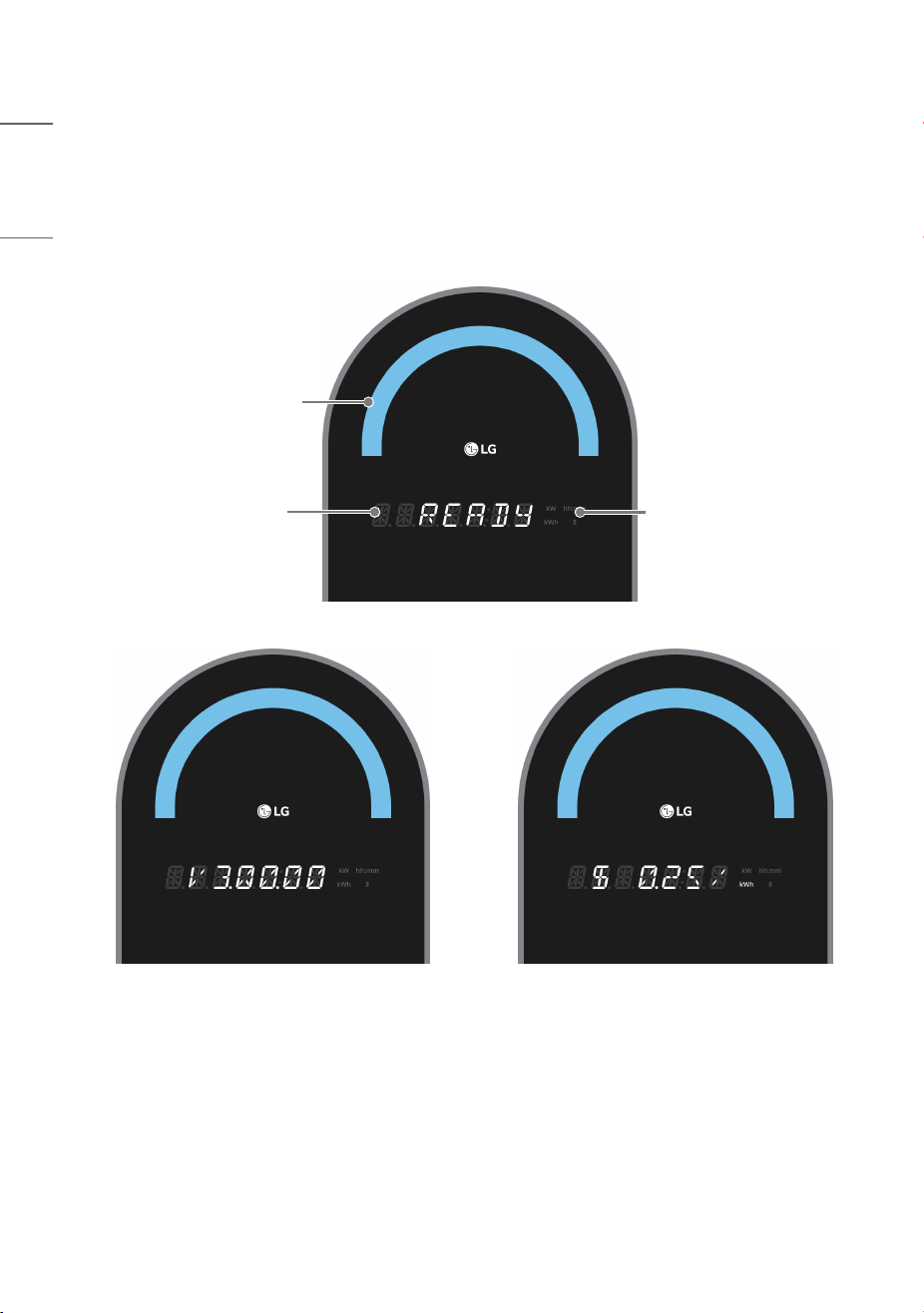
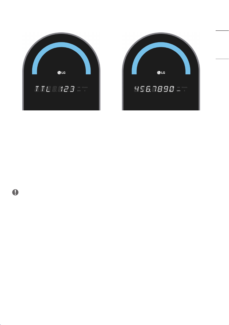
Common Screen Configuration
In the default standby screen, READY, software versions
1)
, charging rates, and total charging power
2)
are displayed at
5-second intervals.
3)
(The total charging power is displayed in kWh up to four decimal places over two screen displays. It can display up to
999999.9999 kWh. If the value is exceeded, it is reset to 0 and displayed.)
Status Indicator LED
7-digit
14Segment
Unit Display
[Software Version] [Charging Rate]
21
ENGLISH
[Total Charging Power]
• The current status of the charger is displayed through the status indicator LED and the strings displayed on 7-digit
14Segment.
• The status indicator LED displays colors like blue/green/red, and effects like blinking/flowing can be added for display.
• The 7-digit 14Segment displays strings like READY/WAIT/PLUG IN/START/STOP/ERROR and information like
charged amount/charging speed/charging time/charging fee.
• On the right of the 7-digit 14Segment, units like kWh/kW/hh:mm/$ are displayed to represent the charged amount/
charging speed/charging time/charging fee.
• For detailed indications depending on the charger’s state, see the screen descriptions by status on the following
pages.
NOTE
•
1)
The software version may change depending on the product’s performance enhancement or function improvement
in the future.
•
2)
Total charging power may change as the product is used.
•
3)
The items displayed may vary depending on the model.
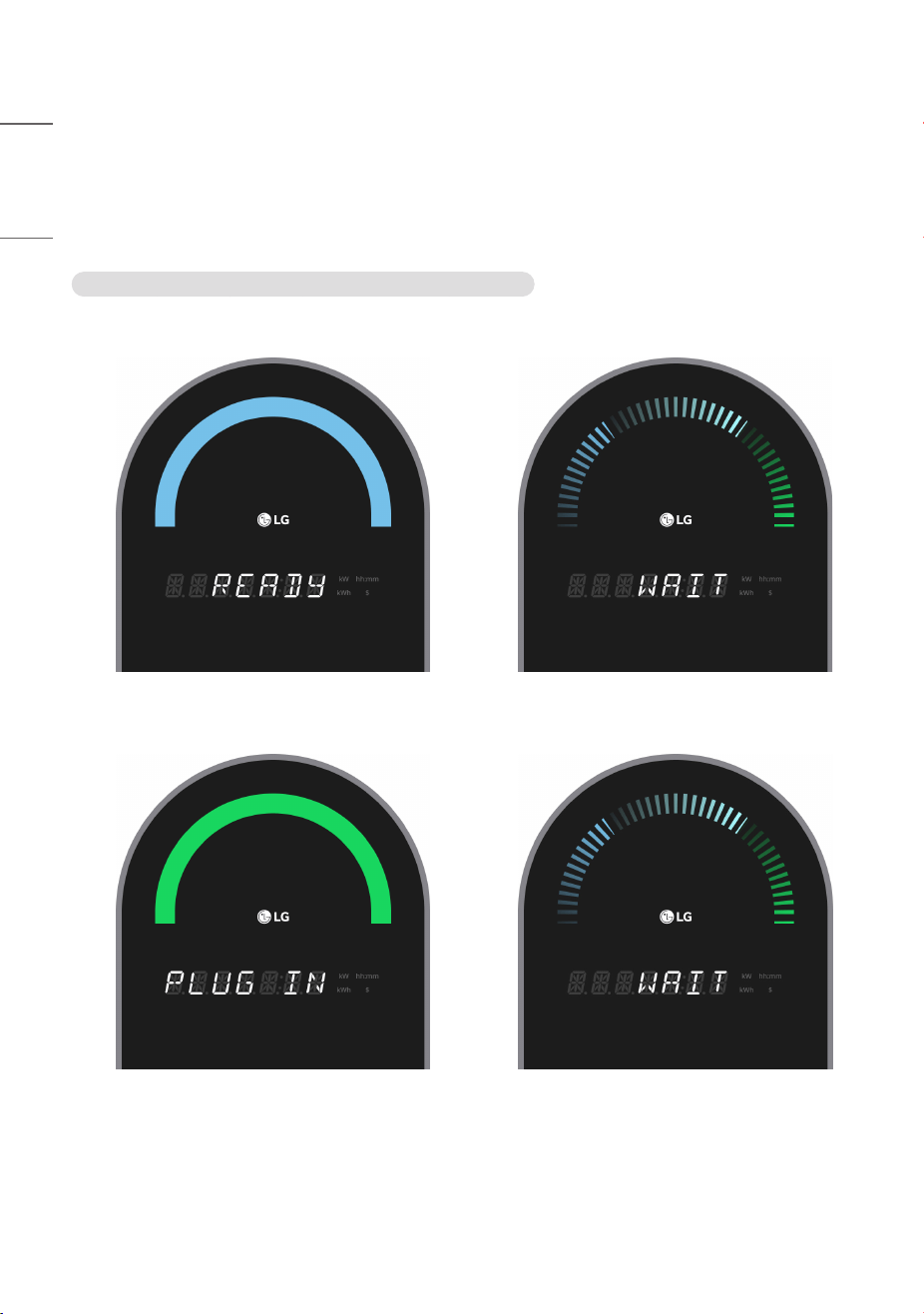
22
ENGLISH
Charging Process
1 To charge, proceed with authentication and connector connection.
(However, the authentication process is not required in private mode, and support for private mode may vary
depending on the model.)
Public mode : If you connect the connector after authentication
a) Tag the membership card (RFID card).
b) Connect the connector.
23
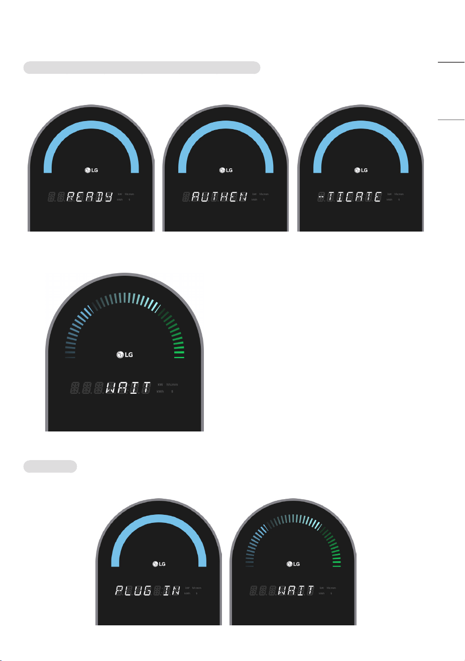
ENGLISH
Public mode : If you authenticate after connecting the connector
a) If you connect the connector on the standby screen, the screen switches to the membership card tag screen.
b) If you tag a membership card (RFID card), the authentication process proceeds.
Private mode
a) Connect the connector on the standby screen.
24
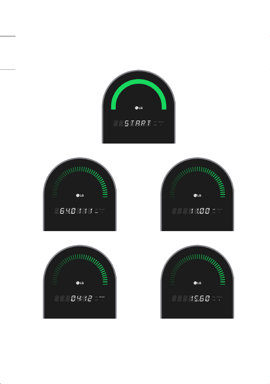
ENGLISH
2 Proceed with charging.
• During charging, the charged amount, charging speed, charging time, and charging fee are changed and displayed
sequentially at 5-second intervals.
1)
• During charging, you can stop charging at any time by tagging your membership card.
[Start charging]
[Charged amount] [Charging speed]
[Charging time] [Charging fee]
1)
The items displayed may vary depending on the model.
25
ENGLISH
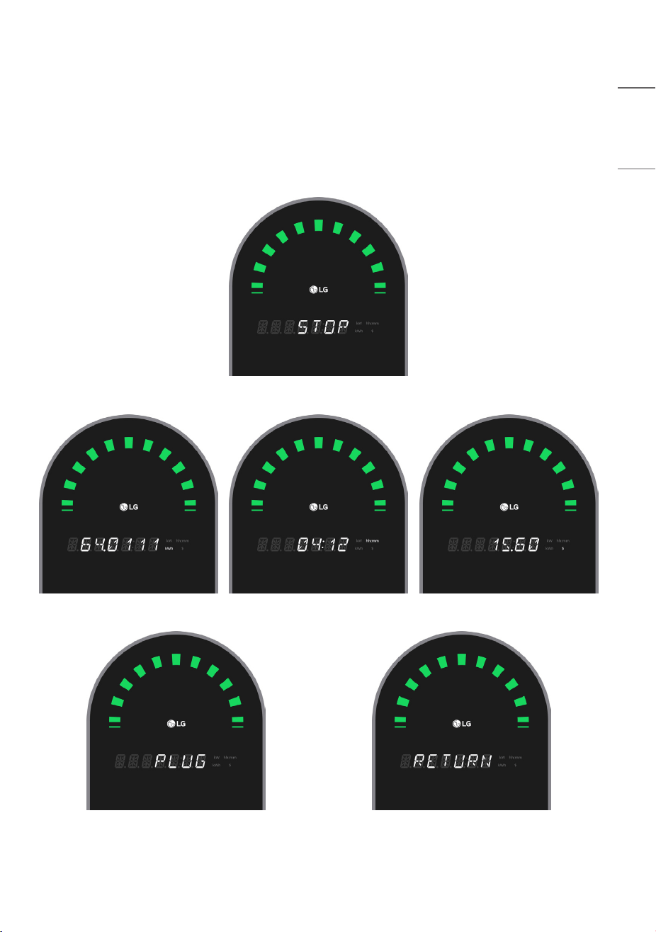
3 Charging ends upon a stop charging request, when fully charged, or after a predetermined time
1)
has elapsed.
• After STOP is displayed for 5 seconds, charging information (charged amount, charging time, charging fee at
5-second intervals) and connector return guidance (PLUG, RETURN at 3-second intervals) are repeatedly displayed.
2)
• The charging information and connector return guidance are displayed two more times after the connector is
detached from the vehicle. (However, once the connector return is completed, it immediately switches to the standby
screen.)
[Charging ended]
[Charged amount] [Charging time] [Charging fee]
[Connector return guidance]
1)
Predetermined time may vary depending on CPO policy.
2)
The items displayed may vary depending on the model.
26
ENGLISH
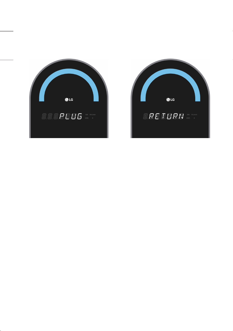
4 If the connector return is not completed when the charging information and connector return guidance are
displayed after charging ends, the connector return guidance (PLUG, RETURN at 3-second intervals) is displayed for
18 seconds, and then it switches to the standby screen. (However, once the connector return is completed, it will
immediately switch to the standby screen.)
27
ENGLISH
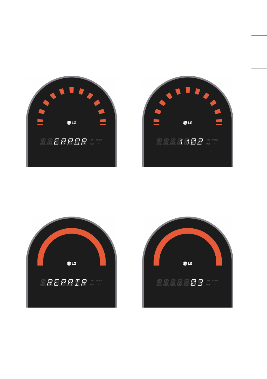
Error Screen
When a failure occurs during charging, during charging preparation, or in the standby state, the details of the failure are
displayed and the charger attempts to recover automatically.
(However, recovery is not attempted in a collision occurrence (error code 6701) situation.)
Error Recovery Screen
After displaying the error content, the automatic recovery screen is displayed for 15 seconds. If recovery is not
completed, the error content is displayed again.
28
ENGLISH
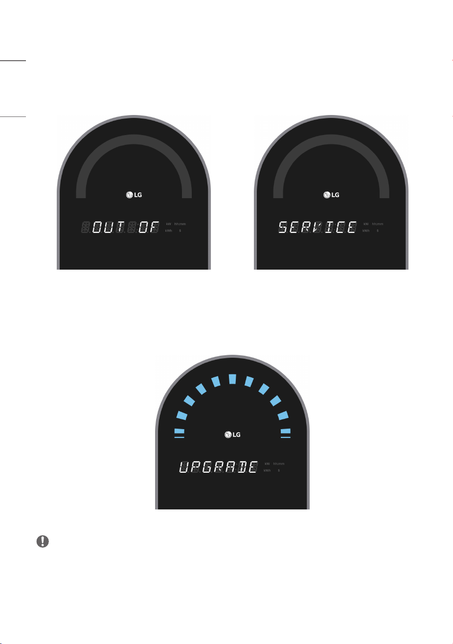
Operation Stop (Availability Change) Screen
This is the screen displayed during a temporary stop in operation due to operation policy. Operation stop and
resumption are possible through remote control of the charging control.
Firmware Download Screen
This is the screen displayed during firmware download via the firmware update command from the charging control.
(This is only displayed under certain statuses, such as “charging possible” status.)
NOTE
• Do NOT turn off the power while the firmware update is in progress.
29
ENGLISH
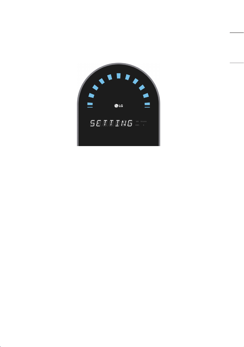
Setting Screen
This is the screen displayed when the charger settings app is connected to the charger.
(The method to connect the charger settings app to the charger is shown in the settings guide document.)

30
ENGLISH
FAULT CODES
WARNING
This device provide an automatic reset feature.
Error Codes Description Solution
1101 Input Overvoltage Detection Charger manufacturer confirmation needed
1102 Input Undervoltage Detection Charger manufacturer confirmation needed
1201 Input Overcurrent Detection Charger manufacturer confirmation needed
1203 AC Leakage Current Error Charger manufacturer confirmation needed
1204 DC Leakage Current Error Charger manufacturer confirmation needed
1301 Ground Connection Abnormality Charger manufacturer confirmation needed
2401/2402 Output Relay Abnormality Charger manufacturer confirmation needed
5114 I2C Communication Abnormality (dry sensor) Charger manufacturer confirmation needed
5201 Electricity Meter Communication Error Charger manufacturer confirmation needed
6102 Control Pilot Abnormality
Try charging again after disconnecting and
reconnecting the connector
6109 Leakage Detection Module Defect Charger manufacturer confirmation needed
6701 Collision Occurrence Charger manufacturer confirmation needed
8101 Charger Internal1 Overheating Charger manufacturer confirmation needed
9201 Other Abnormalities -
10000 RFID Communication Error Charger manufacturer confirmation needed
10002 Control Board Communication Error Charger manufacturer confirmation needed
10003 CPO Communication Error (Network Error)
Verify connection status between control
server and charger
31
ENGLISH
CERTIFICATION
CERTIFICATION Description
FCC FCC Compliance Statement
(For USA)
This equipment has been tested and found to comply with the limits for a Class B digital
device, pursuant to Part 15 of the FCC Rules. These limits are designed to provide
reasonable protection against harmful interference in a residential installation. This
equipment generates, uses, and can radiate radio frequency energy and, if not installed
and used in accordance with the instructions, may cause harmful interference to radio
communications. However, there is no guarantee that interference will not occur in a
particular installation. If this equipment does cause harmful interference to radio or
television reception, which can be determined by turning the equipment off and on, the
user is encouraged to try to correct the interference by one or more of the following
measures:
• Reorient or relocate the receiving antenna.
• Increase the separation between the equipment and the receiver.
• Connect the equipment to an outlet on a circuit different from that to which the
receiver is connected.
• Consult the dealer or an experienced radio/TV technician for help.

32
ENGLISH
CERTIFICATION Description
FCC FCC Notice
(For USA)
This device complies with part 15 of the FCC Rules. Operation is subject to the following
two conditions:
(1) this device may not cause harmful interference and
(2) this device must accept any interference received, including interference that may
cause undesired operation.
Any changes or modifications in construction of this device which are not expressly
approved by the party responsible for compliance could void the user’s authority to
operate the equipment.
FCC Radio Frequency Interference Requirements (for UNII devices)
(For USA)
High power radars are allocated as primary users of the 5.25 to 5.35 GHz and 5.65 to
5.85 GHz bands.
These radar stations can cause interference with and/ or damage this device.
This device cannot be co-located with any other transmitter.
FCC RF Radiation Exposure Statement
(For USA)
[For having wireless function (WLAN, Bluetooth,...)]
This equipment complies with FCC radiation exposure limits set forth for an uncontrolled
environment.
This transmitter must not be co-located or operating in conjunction with any other
antenna or transmitter.
This equipment should be installed and operated with minimum distance 20cm
(7.8inches) between the antenna and your body.
Users must follow the specific operating instructions for satisfying RF exposure
compliance.

33
ENGLISH
CERTIFICATION Description
IC Industry Canada Statement
(For Canada)
[For having wireless function (WLAN, Bluetooth,...)]
This device contains licence-exempt transmitter(s)/ receiver(s) that comply with
Innovation, Science and Economic Development Canada’s licence-exempt RSS(s).
Operation is subject to the following two conditions:
(1) This device may not cause interference.
(2) This device must accept any interference, including interference that may cause
undesired operation of the device.
CAN ICES-003(B) / NMB-003(B)
IC Radiation Exposure Statement
(For Canada)
[For having wireless function (WLAN, Bluetooth,...)]
This equipment complies with IC radiation exposure limits set forth for an uncontrolled
environment.
This equipment should be installed and operated with minimum distance 20cm
(7.8inches) between the antenna & your body.
NOTE: THE MANUFACTURER IS NOT RESPONSIBLE FOR ANY RADIO OR TV
INTERFERENCE CAUSED BY UNAUTHORIZED MODIFICATIONS TO THIS EQUIPMENT.
SUCH MODIFICATIONS COULD VOID THE USER’S AUTHORITY TO OPERATE THE
EQUIPMENT

34
ENGLISH
CERTIFICATION Description
IC RSS-247 Requirement
(For Canada)
[For product having the wireless function using 5 GHz frequency bands]
(1) The device for operation in the band 5150–5250 MHz is only for indoor use to
reduce the potential for harmful interference to co-channel mobile satellite systems;
(2) For devices with detachable antenna(s), the maximum antenna gain permitted for
devices in the bands 5250-5350 MHz and 5470-5725 MHz shall be such that the
equipment still complies with the e.i.r.p. limit;
(3) For devices with detachable antenna(s), the maximum antenna gain permitted for
devices in the band 5725-5850 MHz shall be such that the equipment still complies with
the e.i.r.p. limits as appropriate; and
(4) [For devices operating in the band 5250-5350 MHz having an e.i.r.p. greater than
200 mW] Antenna type(s), antenna models(s), and worst-case tilt angle(s) necessary to
remain compliant with the e.i.r.p. elevation mask requirement set forth in section 6.2.2.3
of RSS-247 shall be clearly indicated.
Users should also be advised that high-power radars are allocated as primary users (i.e.
priority users) of the bands 5250-5350 MHz and 5650-5850 MHz and that these
radars could cause interference and/or damage to LE-LAN devices
35
ENGLISH
CERTIFICATION Description
ENERGY STAR
This product qualifies for ENERGY
STAR®.
Changing the factory default
configuration and settings or
enabling certain optional features
and functionalities may increase
energy consumption beyond the
limits required for ENERGY STAR®
certification.
Refer to ENERGYSTAR.gov for
more information on the ENERGY
STAR® program.
This product qualifies for ENERGY STAR®.
Changing the factory default configuration and settings or enabling certain optional
features and functionalities may increase energy consumption beyond the limits required
for ENERGY STAR® certification.
Refer to ENERGYSTAR.gov for more information on the ENERGY STAR® program.
WARNING: Cancer and Reproductive Harm–
www.P65Warnings.ca.gov.
US only
Temporary noise is normal when powering ON or OFF
this device.
MODEL
SERIAL NO.
The model and serial number of the product are
located on the back and on one side of the product.
Record them below in case you ever need service.
Supplier’s Declaration of Conformity
Trade Name LG
Responsible Party LG Electronics USA, Inc.
Address 111 Sylvan Avenue, North Building,
Englewood Cliffs, NJ 07632
E-mail [email protected]