SPLIT-TYPE AIR CONDITIONERS
English
OPERATING INSTRUCTIONS
For user
• To use this unit correctly and safely, be sure to read these operating
instructions before use.
MSZ-AP25VGD2 MSZ-AP35VGD2 MSZ-AP42VGD2 MSZ-AP50VGD2
MSZ-AP25VGKD2 MSZ-AP35VGKD2 MSZ-AP42VGKD2 MSZ-AP50VGKD2
INDOOR UNIT
En-1
● OPERATING INSTRUCTIONS ●
Contents
Warning
Do not connect the power cord to an intermediate point, use an
extension cord, or connect multiple devices to a single AC outlet.
• Thismaycauseoverheating,re,orelectricshock.
Make sure the power plug is free of dirt and insert it securely into
the outlet.
• Adirtyplugmaycausereorelectricshock.
Do not bundle, pull, damage, or modify the power cord, and do not
apply heat or place heavy objects on it.
• Thismaycausereorelectricshock.
• Sincerotatingpartsandpartswhichcouldcauseanelectricshockareused
in this product, be sure to read these “Safety Precautions” before use.
• Since the cautionary items shown here are important for safety, be sure to
observe them.
• Afterreadingthismanual,keepittogetherwiththeinstallationmanualina
handy place for easy reference.
• Be suretoreceive aguarantee cardfromyour dealerand checkthatthe
purchased date and shop name, etc. are entered correctly.
• Wi-Fi
®
isaregisteredtrademarkofWi-FiAlliance
®
.
Marks and Their Meanings
Warning :
Incorrect handling could cause serious hazard, such as
death, serious injury, etc. with a high probability.
Caution :
Incorrect handling could cause serious hazard depending
on the conditions.
Do not turn the breaker o/on or disconnect/connect the power plug
during operation.
• Thismaycreatesparks,whichcancausere.
• Aftertheindoorunitisswitchedowith the remotecontroller,make
suretoturnthebreakeroordisconnectthepowerplug.
Do not expose your body directly to cool air for a prolonged length
of time.
• This could be detrimental to your health.
Meanings of Symbols Used In This Manual
: Be sure not to do.
: Be sure to follow the instruction.
: Neverinsertyourngerorstick,etc.
: Never step onto the indoor/outdoor unit and do not put anything on
them.
: Dangerofelectricshock.Becareful.
: Be sure to disconnect the power supply plug from the power outlet.
: Besuretoshutothepower.
: Riskofre.
: Never touch with wet hand.
: Never splash water on the unit.
Safety Precautions
Meanings of symbols displayed on indoor unit and/or outdoor unit
Warning
(Riskofre)
Thisunitusesaammablerefrigerant.
Ifrefrigerantleaksandcomesincontactwithreorheatingpart,itwillcreateharmfulgasandthereisriskofre.
Read the OPERATING INSTRUCTIONS carefully before operation.
Service personnel are required to carefully read the OPERATING INSTRUCTIONS and INSTALLATION MANUAL before operation.
FurtherinformationisavailableintheOPERATINGINSTRUCTIONS,INSTALLATIONMANUAL,andthelike.
■ Safety Precautions 1
■ Name of Each Part 4
■ Preparation Before Operation 5
■ Selecting Operation Modes 6
■ Fan Speed and Airflow Direction Adjustment 7
■ I-SAVE Operation 8
■ ECONO COOL Operation 8
■ NIGHT MODE Operation 9
■ TimerOperation(On/OffTimer) 9
■ WeeklyTimerOperation 10
■ Demand Response and Indoor Unit Operation 11
■ Emergency Operation 11
■ Auto Restart Function 11
■ Cleaning 12
■ Wi-FiInterfaceSettingUp(VGKTypeOnly) 13
■ WhenYouThinkThatTroubleHasOccurred 16
■ When the Air Conditioner Is Not Going to Be Used for a Long Time 17
■ InstallationPlaceandElectricalWork 18
■ Specifications 18
En-2En-2
The unit should not be installed, relocated, disassembled, altered,
or repaired by the user.
• Animproperlyhandledairconditionermaycausere,electricshock,
injury,orwaterleakage,etc.Consultyourdealer.
• If the power supply cord is damaged, it must be replaced by the manu-
facturer or its service agent in order to avoid a hazard.
When installing, relocating, or servicing the unit, make sure that
no substance other than the specied refrigerant (R32) enters the
refrigerant circuit.
• Any presence of foreign substance such as air can cause abnormal
pressure rise and may result in explosion or injury.
• Theuseofanyrefrigerantotherthanthatspeciedforthesystemwill
causemechanicalfailure,systemmalfunction,orunitbreakdown.Inthe
worst case, this could lead to a serious impediment to securing product
safety.
This appliance is not intended for use by persons (including children)
with reduced physical, sensory or mental capabilities, or lack of ex-
perience and knowledge, unless they have been given supervision or
instruction concerning use of the appliance by a person responsible
for their safety.
Children should be supervised to ensure that they do not play with
the appliance.
Do not insert your nger, a stick, or other objects into the air inlet
or outlet.
• This may cause injury, since the fan inside rotates at high speeds during
operation.
In case of an abnormal condition (such as a burning smell), stop the
air conditioner and disconnect the power plug or turn the breaker o.
• A continued operation in the abnormal state may cause a malfunction,
re,orelectricshock.Inthiscase,consultyourdealer.
When the air conditioner does not cool or heat, there is a possibility of
refrigerant leakage. If any refrigerant leakage is found, stop operations
and ventilate the room well and consult your dealer immediately. If a
repair involves recharging the unit with refrigerant, ask the service
technician for details.
• The refrigerant used in the air conditioner is not harmful. Normally, it
doesnotleak.However,ifrefrigerantleaksandcomesincontactwith
reorheatingpartofsuchafanheater,keroseneheater,orcooking
stove,itwillcreateharmfulgasandthereisriskofre.
The user should never attempt to wash the inside of the indoor unit.
Should the inside of the unit require cleaning, contact your dealer.
• Unsuitable detergent may cause damage to plastic material inside
theunit,whichmayresultinwaterleakage.Shoulddetergentcomein
contact with electrical parts or the motor, it will result in a malfunction,
smoke,orre.
• The appliance shall be stored in a room without continuously operating
ignitionsources(forexample:openames,anoperatinggasappliance
oranoperatingelectricheater).
• Be aware that refrigerants may not contain an odour.
• Do not use means to accelerate the defrosting process or to clean the
appliance, other than those recommended by the manufacturer.
• Do not pierce or burn.
The indoor unit must be installed in rooms which exceed the oor
space specied. Please consult your dealer.
This appliance is intended to be used by expert or trained users in
shops, in light industry and on farms, or for commercial use by lay
persons.
Caution
Do not touch the air inlet or the aluminum ns of the indoor/outdoor
unit.
• This may cause injury.
Do not use insecticides, ammable sprays, air refreshers, or antibac-
terial agents on the unit.
• Thismaycauseareordeformationoftheunit.
Do not expose pets or houseplants to direct airow.
• This may cause injury to the pets or plants.
Do not place other electric appliances or furniture under the indoor/
outdoor unit.
• Water may drip down from the unit, which may cause damage or
malfunction.
Do not leave the unit on a damaged installation stand.
• The unit may fall and cause injury.
Do not step on an unstable bench to operate or clean the unit.
• This may cause injury if you fall down.
Do not pull the power cord.
• Thismaycauseaportionofthecorewiretobreak,whichmaycause
overheatingorre.
Do not charge or disassemble the batteries, and do not throw them
into a re.
•
Thismaycausethebatteriestoleak,orcauseareorexplosion.
Safety Precautions
Do not operate the unit for more than 4 hours at high humidity (80%
RH or more) and/or with windows or outside door left open.
• This may cause the water condensation in the air conditioner, which
may drip down, wetting or damaging the furniture.
• The water condensation in the air conditioner may contribute to growth
of fungi, such as mold.
Do not use the unit for special purposes, such as storing food,
raising animals, growing plants, or preserving precision devices
or art objects.
• This may cause deterioration of quality, or harm to animals and plants.
Do not expose combustion appliances to direct airow.
• This may cause incomplete combustion.
Never put batteries in your mouth for any reason to avoid accidental
ingestion.
• Batteryingestionmaycausechokingand/orpoisoning.
Before cleaning the unit, switch it o and disconnect the power plug
or turn the breaker o.
• This may cause injury, since the fan inside rotates at high speeds during
operation.
When the unit will be unused for a long time, disconnect the power
plug or turn the breaker o.
• Theunitmayaccumulatedirt,whichmaycauseoverheatingorre.
Replace all batteries of the remote controller with new ones of the
same type.
• Using an old battery together with a new one may cause overheating,
leakage,orexplosion.
If the battery uid comes in contact with your skin or clothes, wash
them thoroughly with clean water.
•
Ifthebatteryuidcomesincontactwithyoureyes,washthemthoroughly
withcleanwaterandimmediatelyseekmedicalattention.
Ensure that the area is well-ventilated when the unit is operated
together with a combustion appliance.
• Inadequate ventilation may cause oxygen starvation.
Do not operate the air conditioner after applying protecting agent
on the oor.
• Theunitmaybedamagediflightningstrikes.
Turn the breaker o when you hear thunder and there is a possibility
of a lightning strike.
• Components in the protecting agent may attach the inside of the indoor
unit,resultinginwaterleakageorsplatteringofdew.
After the air conditioner is used for several seasons, perform inspec-
tion and maintenance in addition to normal cleaning.
• Dirt or dust in the unit may create an unpleasant odor, contribute to
growth of fungi, such as mold, or clog the drain passage, and cause
watertoleakfromtheindoorunit.Consultyourdealerforinspection
andmaintenance,whichrequirespecializedknowledgeandskills.
Do not operate switches with wet hands.
• Thismaycauseelectricshock.
Do not clean the air conditioner with water or place an object that
contains water, such as a ower vase, on it.
• Thismaycausereorelectricshock.
Do not step on or place any object on the outdoor unit.
• This may cause injury if you or the object falls down.
Important
Dirty lters cause condensation in the air conditioner which will contribute to the
growth of fungi such as mold. It is therefore recommended to clean air lters every
2 weeks.
Before starting the operation, ensure that the horizontal vanes are in the closed posi-
tion. If operation starts when the horizontal vanes are in the open position, they may
not return to the correct position.
En-3
● OPERATING INSTRUCTIONS ●
Safety Precautions
Warning
(Improper handling may have serious consequences, including serious
injuryordeath.)
This appliance can be used by children aged from 8 years and above
and persons with reduced physical, sensory or mental capabilities or
lack of experience and knowledge if they have been given supervi-
sion or instruction concerning use of the appliance in a safe way and
understand the hazards involved.
Children shall not play with the appliance. Cleaning and user mainte-
nance shall not be made by children without supervision.
Do not use the Wi-Fi interface nearby the medical electrical equipment
or people who have a medical device such as a cardiac pacemaker
or an implantable cardioverter-debrillator.
• It can cause an accident due to malfunctions of the medical equipment
or device.
Do not install the Wi-Fi interface nearby the automatic control devices
such as automatic doors or re alarms.
• It can cause accidents due to malfunctions.
Do not touch the Wi-Fi interface with wet hands.
• Itcancausedamagetothedevice,electricshock,orre.
Do not splash water on the Wi-Fi interface or use it in a bathroom.
• Itcancausedamagetothedevice,electricshock,orre.
When the Wi-Fi interface is dropped, or the holder or cable is damaged,
disconnect the power supply plug or turn the breaker o.
• Itmaycausereorelectricshock.Inthiscase,consultyourdealer.
•
This device complies with all Australia and New zealand
regulrements for EMC and electrical safety.
Caution
(Improper handling may have consequences, including injury or damage
tobuilding.)
Do not step on unstable stepstool to set up or clean the Wi-Fi interface.
• It may cause injury if you fall down.
Do not use the Wi-Fi interface nearby other wireless devices, micro-
waves, cordless phones, or facsimiles.
• It can cause malfunctions.
For Wi-Fi Interface
Warning
Consult your dealer for installing the air conditioner.
• It should not be installed by the user since installation requires specialized
knowledgeandskills.Animproperlyinstalledairconditionermaycause
waterleakage,re,orelectricshock.
Provide a dedicated power supply for the air conditioner.
• Anon-dedicatedpowersupplymaycauseoverheatingorre.
Do not install the unit where ammable gas could leak.
• Ifgasleaksandaccumulatesaroundtheoutdoorunit,itmaycausean
explosion.
Earth the unit correctly.
• Do not connect the earth wire to a gas pipe, water pipe, lightning rod, or
atelephoneearthwire.Improperearthingmaycauseelectricshock.
Caution
Install an earth leakage breaker depending on the installation location
of the air conditioner (such as highly humid areas).
• Ifanearthleakagebreakerisnotinstalled,itmaycauseelectricshock.
Ensure that the drain water is properly drained.
• If the drain passage is improper, water may drip down from the indoor/
outdoor unit, wetting and damaging the furniture.
In case of an abnormal condition
Immediately stop operating the air conditioner and consult your dealer.
For Installation
En-4
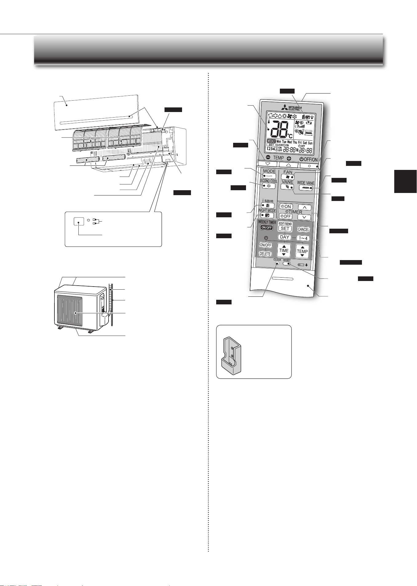
Operation indicator lamp
Remote control receiving
section
Emergency
operation
switch
Page 11
Horizontal vane
Air inlet
Airlter
Aircleaninglter
(Anti-Allergy
Enzymelter)
(Electrostatic
anti-allergy
enzymelter,
option)
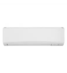
Front panel
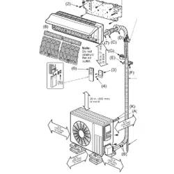
Name of Each Part
Indoor unit Remote controller
Signal transmitting
section
Distance of signal :
About 6 m
Beep(s)is(are)heardfrom
the indoor unit when the
signal is received.
Operation dis-
play section
O/on(stop/operate)
button
Temperature
buttons
Page 6
Operation
select button
Page 6
ECONO COOL
button
Page 8
Fan speed control
button
Page 7
Vane control button
Page
Time, Timer set buttons
Page 7, 9
Increase time
Decrease time
Clockbutton
Page 5
Reset button Page 5
Lid
Slide the lid down
to open the remote
controller. Slide it down
further to get to the
weeklytimerbuttons.
Only use the remote controller provided
with the unit.
Do not use other remote controllers.
If 2 or more indoor units are installed in
proximity to one another, an indoor unit
that is not intended to be operated may
respond to the remote controller.
I-SAVE button
Page 8
Weeklytimersetbut-
tons
Page5,10
Air outlet
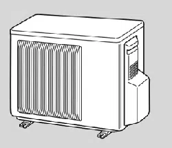
Outdoor unit
Outdoorunitsmaybedierentinappearance.
Airinlet(backandside)
Refrigerant piping
Drainage hose
Air outlet
Drain outlet
Wide vane button
Page 7
NIGHT MODE
button
Page 9
Battery replacement indicator Page 5
Heat exchanger
Remote controller holder
• Install the remote
controller holder in a
place where the signal
can be received by the
indoor unit.
• When the remote
controller is not used,
place it in this holder.
Wi-Fi interface
Page13
Fan guard
En-5
● OPERATING INSTRUCTIONS ●
Before operation: Insert the power supply plug into the power outlet and/or
turnthebreakeron.
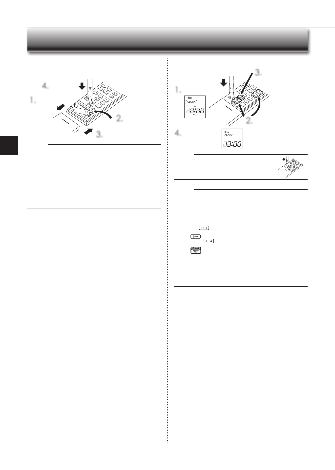
Installing the remote controller batteries
1.
Remove the front lid.
2.
Insert the negative
poleofAAAalkaline
batteriesrst.
3.
Install the front lid.
4.
Press reset
button.
Setting current time
1.
Pressclockbutton.
4.
Pressclockbutton
again.
2.
Press either the time button
or the timer buttons to set the
time.
Each press increases/decreas-
esthetimeby1minute(10
minuteswhenpressedlonger).
3.
Press the dry button
to set the day.
Preparation Before Operation
Note:
• Makesurethepolarityofthebatteriesiscorrect.
• Donotusemanganesebatteriesandleakingbatteries.Theremotecontroller
could malfunction.
• Do not use rechargeable batteries.
• The battery replacement indicator lights up when the battery is running low.
In about 7 days after the indicator starts lights up, the remote controller stops
working.
• Replace all batteries with new ones of the same type.
• Batteries can be used for approximately 1 year. However, batteries with ex-
pired shelf lives last shorter.
• Press reset button gently using a thin instrument.
If the reset button is not pressed, the remote controller may not operate cor-
rectly.
Note:
• Pressclockbuttongentlyusingathininstrument.
Note:
How to set remote controller exclusively for a particular indoor unit
A maximum of 4 indoor units with wireless remote controllers can be used in
a room.
To operate the indoor units individually with each remote controller, assign a
number to each remote controller according to the number of the indoor unit.
This setting can be set only when all the following conditions are met:
• Theremotecontrollerispoweredo.
(1)Holddown
button on the remote controller for 2 seconds to enter the
pairing mode.
(2)Press
button again and assign a number to each remote controller.
Each press of
buttonadvancesthenumberinthefollowingorder:1→
2→3→4.
(3)Press
button to complete the pairing setting.
Afteryouturnthebreakeron,theremotecontrollerthatrstsendsasignal
to an indoor unit will be regarded as the remote controller for the indoor unit.
Once they are set, the indoor unit will only receive the signal from the as-
signed remote controller afterwardsThe setting indoor unit will be cancelled,
ifthebreakeristurnedoorthepowersupplyisshutdown.
Thesettingindoorunitwillbecancelled,ifthebreakeristurnedoorthe
power supply is shut down.
En-6
Auto Mode (Auto Change Over)
Theunitselects the operationmodeaccording to the dierencebetween
the room temperature and the set temperature. During auto mode, the unit
changesmode(cool↔mode)whentheroomtemperatureisabout2°Caway
from the set temperature for more than 15 minutes.
Note:
Auto mode is not recommended if this indoor unit is connected to a MXZ
type outdoor unit. When several indoor units are operated simultaneously,
the unit may not be able to switch operation mode between cool and heat
mode. In this case, the indoor unit becomes standby mode (Refer to table
ofOperationindicatorlamp).
Cool Mode
Enjoy cool air at your desired temperature.
Note:
Do not operate cool mode at very low outside temperatures (less than
-10°C).Watercondensedintheunitmaydripandwetordamagefurni-
ture, etc.
Note:
Multi syste m operation
Two or more indoor units can be operated by one outdoor unit. When several
indoor units are operated simultaneously, cooling/dry/fan mode and heating op-
erations cannot be done at the same time. When cool/dry/fan mode is selected
with one unit and heat mode with another or vice versa, the unit selected last
goes into standby mode.
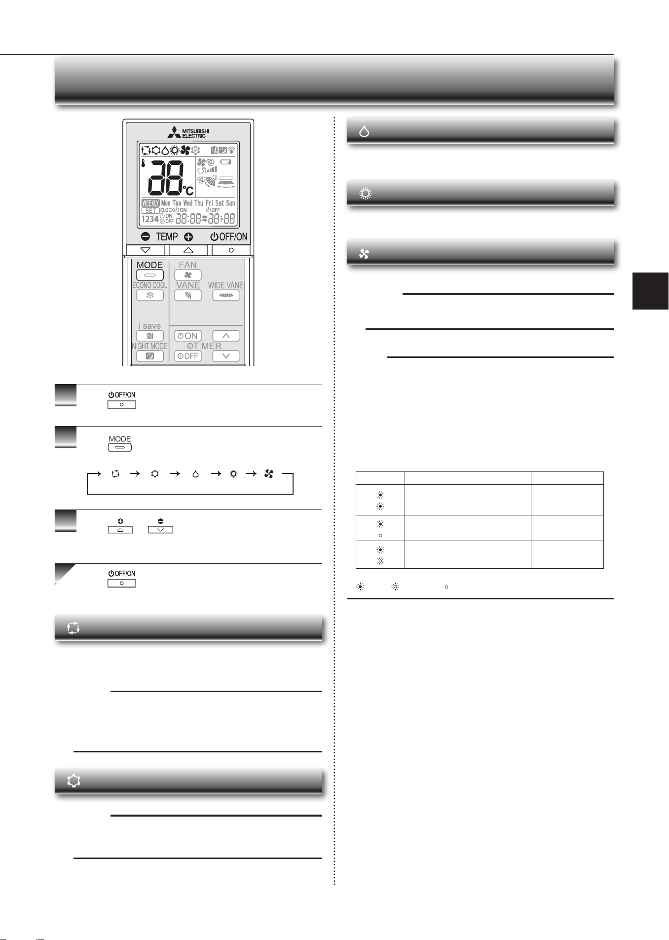
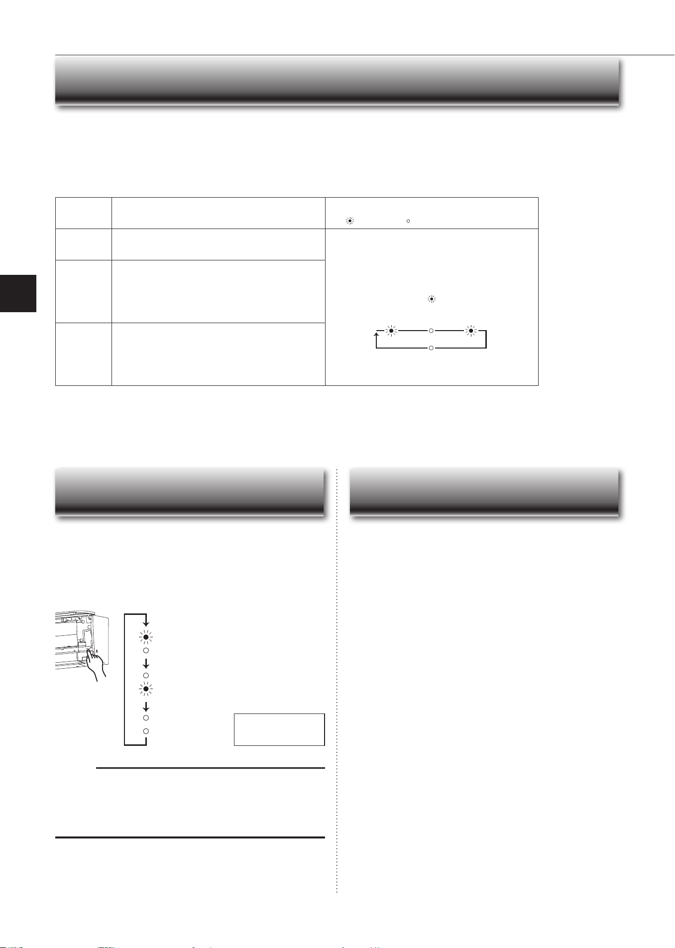
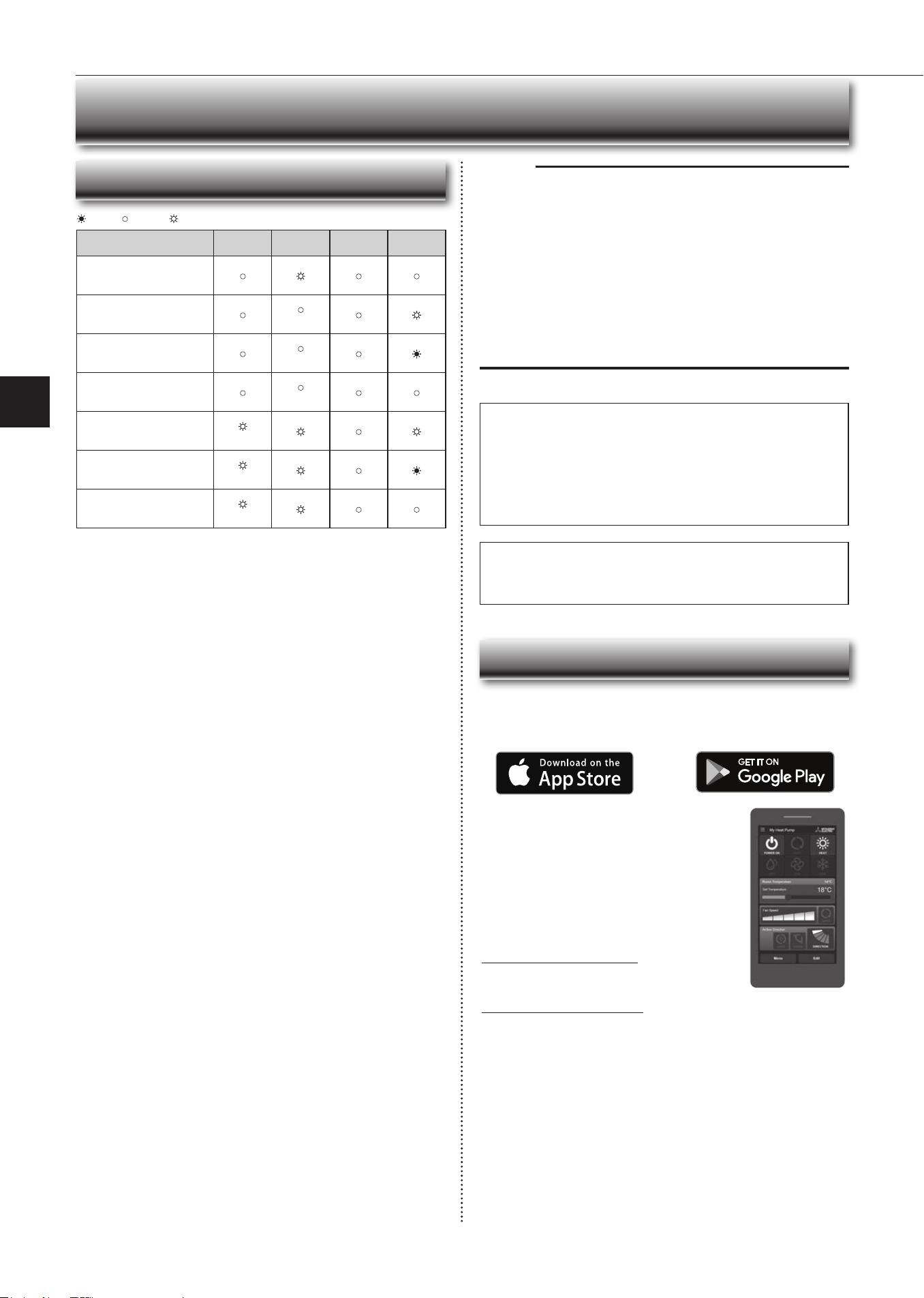
Operation indic a t or lamp
The operation indicator lamp shows the operation state of the unit.
Indication Operation state Room temperature
The unit is operating to reach the set
temperature
About2°Cor more
away from set tem-
perature
The room temperature is approach-
ing the set temperature
About1to2°Cfrom
set temperature
Standby mode (only during multi
systemoperation)
—
Lit Blinking Not lit
1
Press
to start the operation.
2
Press to select operation mode. Each press
changes mode in the following order:
3
Press or to set the temperature.
Eachpressraisesorlowersthetemperatureby1°C.
Press to stop the operation.
Selecting Operation Modes
(Auto) (Cool) (Dry) (Heat) (Fan)
Dry Mode
Dehumidify your room. The room may be cooled slightly.
Temperature cannot be set during dry mode.
Heat Mode
Enjoy warm air at your desired temperature.
Fan Mode
Circulate the air in your room.
Note:
After cool/dry mode operation, it is recommended to operate in the fan
mode to dry inside the indoor unit.
En-7
● OPERATING INSTRUCTIONS ●
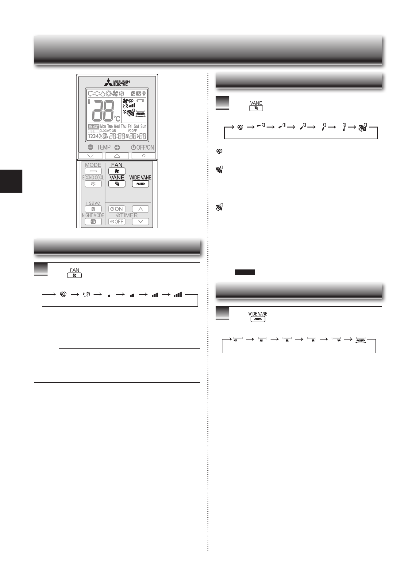
1
Press to select fan speed. Each press changes
fan speed in the following order:
• Two short beeps are heard from the indoor unit when set to auto.
•Usehigherfanspeedtocool/heattheroomquicker.Itisrecommended
to lower the fan speed once the room is cool/warm.
• Use lower fan speed for quiet operation.
Note:
Multi syste m operation
When several indoor units are operated simultaneously by one outdoor unit for
heatingoperation,thetemperatureoftheairowmaybelow.Inthiscase,itis
recommended to set the fan speed to auto.
(Auto) (Quiet) (Low) (Med.) (High) (SuperHigh)
1
Press toselectairowdirection.Eachpress
changesairowdirectioninthefollowingorder:
(Auto) ...........Thevaneissettothemostecientairowdirection.Cool/dry/
fan mode: horizontal position. Heat mode: downward.
(Manual) .......For efficient air conditioning, select the upper position for cool/
dry mode, and the lower position for heat mode. If the lower
position is selected during cool/dry mode, the vane automati-
callymovestotheupwardpositionafter0.5to1hourtoprevent
any condensation from dripping.
(Swing) .........The vane moves up and down intermittently.
• Two short beeps are heard from the indoor unit when set to auto.
• Always use the remote controller when changing the direction of air-
flow. Moving the horizontal vanes with your hands causes them to mal-
function.
• Whenthebreakeristurnedon,thehorizontalvanes’positionwillbe
reset in about a minute, then the operation will start. The same is true
in the emergency cooling operation.
• When the horizontal vanes seem to be in an abnormal position, see
page 16
.
(Auto) (1) (2) (3) (4) (5) (Swing)
Fan Speed and Airow Direction Adjustment
1
Press toselectairowdirection.Eachpress
changesairowdirectioninthefollowingorder:
(
Swing
)
Left-Right Airflow Direction
Fan Speed
Up-Down Airflow Direction
En-8
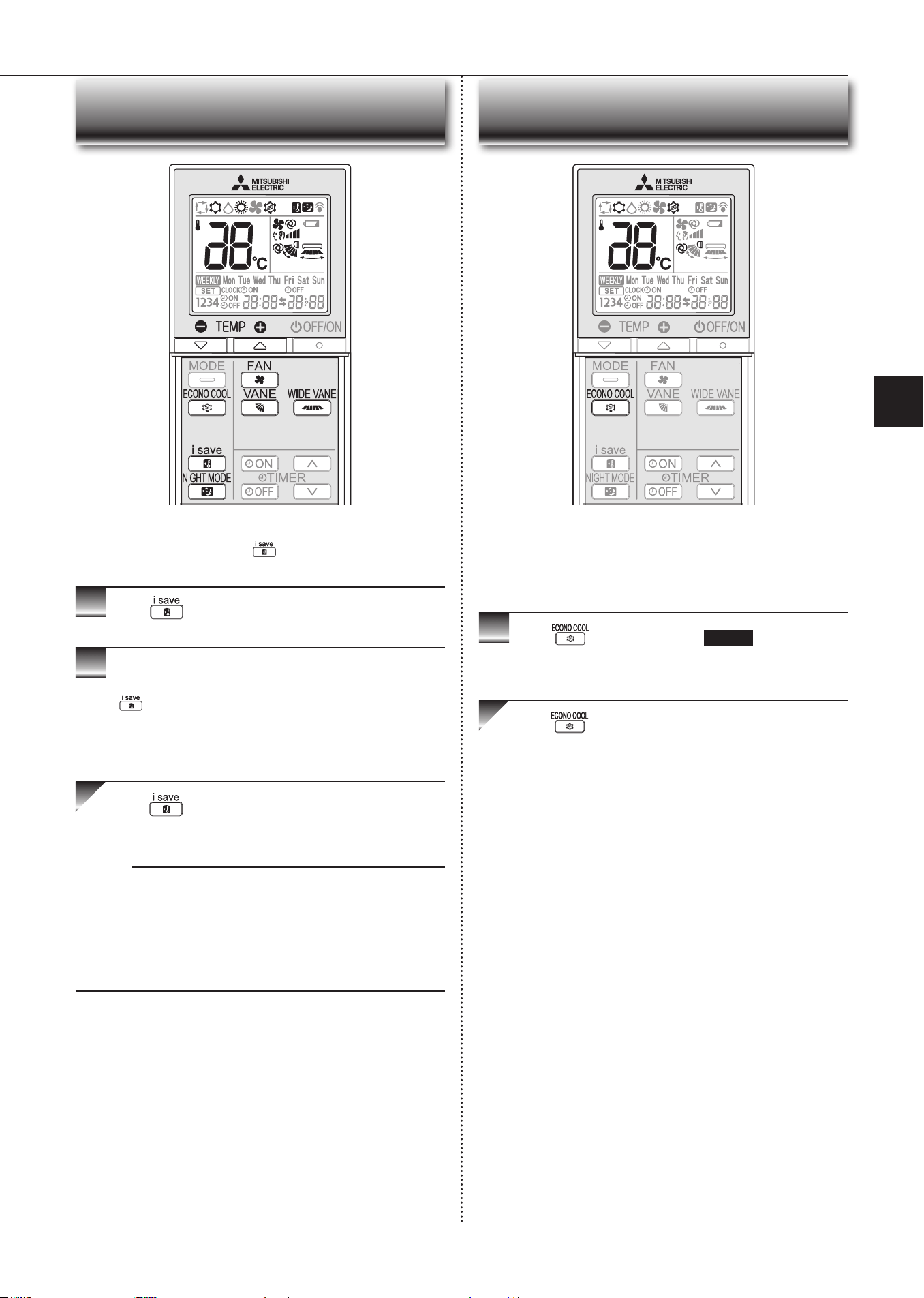
I-SAVE Operation
1
Press during cool mode, ECONO COOL, heat
mode or NIGHT MODE to select I-SAVE mode.
2
Setthetemperature,fanspeed,andairowdirection.
• The same setting is selected from the next time by simply pressing
.
• Two settings can be saved. (One for cool mode, ECONO COOL, one
forheatmode)
• Select the appropriate temperature, fan speed, and airflow direction
according to your room.
Press again to cancel I-SAVE operation.
• I-SAVE operation also is cancelled when the Operation select button is
pressed.
Note:
Example of use:
1. Low energy mode
Setthe temperature2°Cto 3°Cwarmer inCoolandcoolerin Heatmode.
This setting is suitable for unoccupied room, and while you are sleeping.
2. Saving frequently used settings
Save your preferred setting for cool mode, ECONO COOL, heat mode and
NIGHT MODE. This enables you to select your preferred setting with a single
push of the button.
Asimpliedsetbackfunctionenablestorecallthepreferred(preset)
setting with a single push of the
button. Press the button again
andyoucangobacktotheprevioussettinginaninstance.
ECONO COOL Operation
1
Press during Cool mode page 6 to start ECO-
NO COOL operation.
The unit performs swing operation vertically in various cycles according to the
temperature airflow.
Press again to cancel ECONO COOL operation.
• ECONO COOL operation is also cancelled when the VANE button is
pressed.
Swingairow(changeofairow)makesyoufeelcoolerthanstation-
aryairow.
Thesettemperatureandtheairowdirectionareautomaticallychanged
by the microprocessor. It is possible to perform cooling operation with
keepingcomfort.Asaresultenergycanbesaved.
En-9
● OPERATING INSTRUCTIONS ●
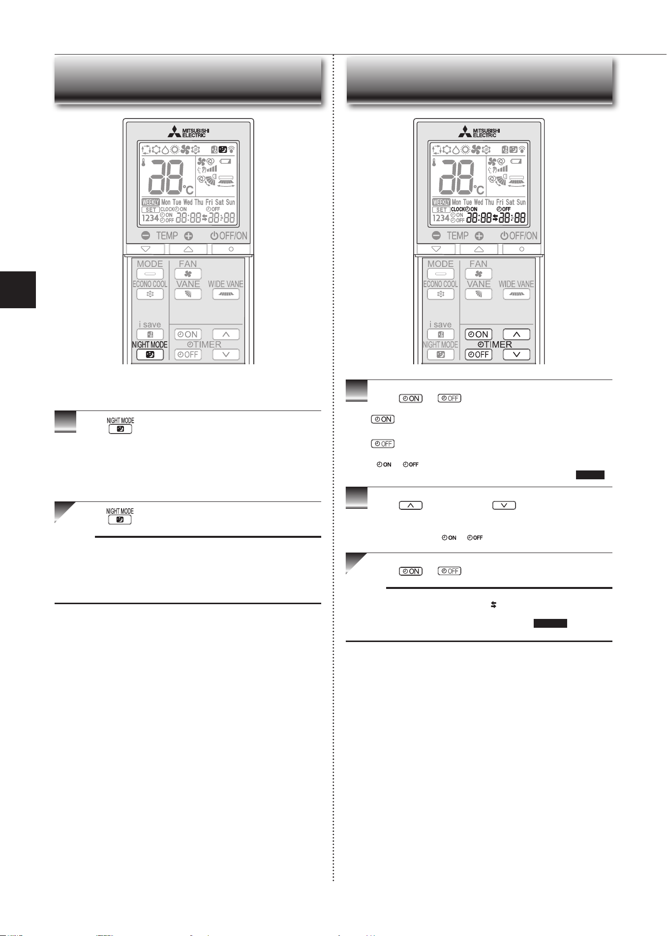
NIGHT MODE Operation
1
Press during operation to activate NIGHT MODE.
• The operation indicator lamp dims.
• The beep sound will be disabled except that emitted when the opera-
tion is started or stopped.
• Noise level of the outdoor unit will be lower than that mentioned in
SPECIFICATIONS.
Press again to cancel NIGHT MODE.
Note:
• The cooling/heating capacity may drop.
• Noise level of the outdoor unit may not change after start-up of the unit, dur-
ing the protection operation, or depending on other operating conditions.
• The fan speed of the indoor unit will not change.
•
The operation indicator lamp will be hard to be seen in a bright room.
•
Noise level of the outdoor unit will not decrease during Multi system operation.
NIGHT MODE changes the brightness of the operation indicator,
disables the beep sound and limits the noise level of the outdoor unit.
1
Press or during operation to set the timer.
(ontimer): Theunitturnsonatthesettime.
(otimer): Theunitturnsoatthesettime.
*
or blinks.
*
Make sure that the current time and day are set correctly.
Page 5
2
Press (Increase)and (Decrease)tosetthe
time of timer.
Eachpressincreasesordecreasesthesettimeby10minutes.
• Set the timer while
or isblinking.
Press
or
again to cancel timer.
Note:
• On ando timerscanbesettogether.
markindicatestheorderoftimer
operations.
• Ifpowerfailureoccurswhileon/otimerisset,see
page 11 “Auto restart
function”.
Timer Operation (On/O Timer)
En-10
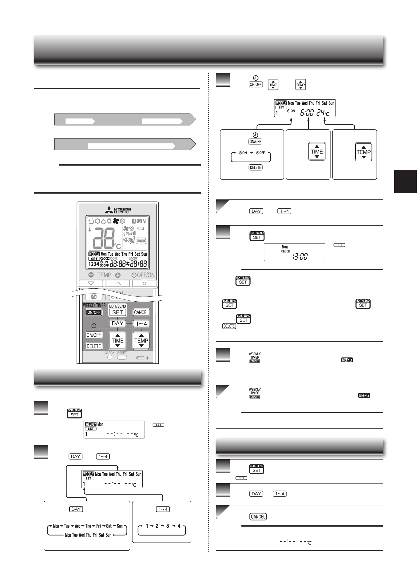
Weekly Timer Operation
• Amaximumof4onorotimerscanbesetforindividualdaysoftheweek.
• Amaximumof28onorotimerscanbesetforaweek.
Setting the Weekly Timer
* Makesurethatthecurrenttimeanddayaresetcorrectly.
1
Press toentertheweeklytimersettingmode.
2
Press and to select setting day and number.
3
Press , , and toseton/o,time,and
temperature.
Press and to continue setting the timer for
other days and/or numbers.
4
Press tocompleteandtransmittheweeklytimer
setting.
Note:
• Press totransmitthesettinginformationofweeklytimertotheindoor
unit.Pointtheremotecontrollertowardtheindoorunitfor3seconds.
• Whensettingthetimerformorethanonedayoftheweekoronenumber,
does not have to be pressed per each setting. Press once
afterallthesettingsarecomplete.Alltheweeklytimersettingswillbesaved.
• Press
toenterthe weekly timer setting mode, and press andhold
for 5 seconds to erase all weekly timer settings. Point the remote
controller toward the indoor unit.
5
Press toturntheweeklytimeron.( lights.)
* Whentheweeklytimerison,thedayoftheweekwhosetimersetting
is complete, will light.
Press againtoturntheweeklytimero.(
goesout.)
Note:
Thesavedsettingswillnotbeclearedwhentheweeklytimeristurnedo.
Checking Weekly Timer Setting
1
Press toentertheweeklytimersettingmode.
* blinks.
2
Press or to view the setting of the particular
day or number.
Press toexittheweeklytimersetting.
Note:
Whenalldaysoftheweekareselectedtoviewthesettingsandadierent set-
ting is included among them,
will be displayed.
*
whichwasblink-
ing goes out, and the
current time will be
displayed.
*
blinks.
Note:
Thesimpleon/otimersettingisavailablewhiletheweeklytimerison.Inthis
case,theon/otimerhaspriorityovertheweeklytimer;theweeklytimeropera-
tionwillstartagainafterthesimpleon/otimeriscomplete.
E.g. : Runs at 24°C from waking up to leaving home, and runs at 27°C
from getting home to going to bed on weekdays.
Runs at 27°C from waking up late to going bed early on weekends.
Setting1 Setting2 Setting3 Setting4
Setting1 Setting2
6:00 8:30 17:30 22:00
8:00 21:00
24°C 27°C
ON OFF ON OFF
ON OFF
Mon
Fri
~
Sat
Sun
~
27°C
Pressing selects the day of
theweektobeset.
Pressing selects
the setting number.
* All days can be selected.
E.g. : [Mon Tue ... Sun]
and [1] are selected.
E.g.: [ON],[6:00]
and[24°C]are
selected.
Pressing
selects
on/otimer.
Pressing
deletes
timer setting.
Pressing
adjusts the time.
Pressing
adjusts the tem-
perature.
* Holddownthebuttontochangethetimequickly.
En-11
● OPERATING INSTRUCTIONS ●
Demand response
ThisunithasdemandresponsecapabilitywhichiscompliantwithAS/NZS4755.3.1.
Toactivatethisfunction,youneedtomakeacontractwithremoteagentssuchaselectricsupplycompany,thenthisunitshouldbeconnectedtoDemandresponseenabling
devise(DRED).Forfurtherinformation,consultyourdealer.
Demandresponserepresentstheautomatedalterationofanelectricalproduct’snormalmodeofoperationinresponsetoaninitiatingsignaloriginatingfromordened
by a remote agent.
Thisunitsupports3DemandResponseModes(DRMs).
DRM Description of operation in this mode
Operation indicator lamp
Lit Not lit
DRM 1
Compressoro
The air conditioner does not perform cooling or heating opera-
tion during the demand response event.
Upper lamp is lit.
Lowerlampblinks.
2.5 sec 2.5 sec0.5 sec
2.5 sec
DRM 2
The air conditioner continues to perform cooling or heating
operation during the demand response event, but the elec-
trical energy consumed by the air conditioner in a half hour
period is not more than 50% of the total electrical energy
that would be consumed if operating at the rated capacity in
a half hour period.
DRM3
The air conditioner continues to perform cooling or heating
operation during the demand response event, but the elec-
trical energy consumed by the air conditioner in a half hour
period is not more than 75% of the total electrical energy
that would be consumed if operating at the rated capacity in
a half hour period.
Note:
• DRM is automatically activated or released according to the signals from DRED.
DRM cannot be invalidated or changed manually.
•YoumightfeelthisunitdoesnotsucientlyperformcoolingorheatingoperationduringDRM.
• Operation settings can be changed as usual with the remote controller during DRM.
However, you might not feel cool or warm enough as DRM is prioritized.
Demand Response And Indoor Unit Operation (Demand Type Only)
Ifapowerfailureoccursorthemainpoweristurnedoduringoperation,“Auto
restart function” automatically starts operation in the same mode as the one set
withtheremotecontrollerjustbeforetheshutoofthemainpower.Whentimeris
set, timer setting is cancelled and the unit starts operation when power is resumed.
If you do not want to use this function, please consult the service repre-
sentative because the setting of the unit needs to be changed.
Auto Restart Function
Operation indicator lamp
When the remote controller cannot be used...
Emergency operation can be activated by pressing the emergency operation
switch(E.O.SW)ontheindoorunit.
Each time the E.O.SW is pressed, the operation changes in
the following order:
Settemperature:24°C
Fan speed : Medium
Horizontal vane : Auto
Emergency cooling operation
Emergency heating operation
Stop
Note:
• Therst30minutesofoperationistestrun.Temperaturecontroldoesnot
work,andfanspeedissettoHigh.
• In the emergency heating operation, the fan speed gradually rises to blow out
warm air.
• In the emergency cooling operation, the horizontal vanes’ position will be
reset in about a minute, then the operation will start.
Emergency Operation
En-12
1.Liftthefrontpaneluntila“click”isheard.
2. Hold the hinges and pull to remove as shown in the illustration above.
• Wipe with a soft dry cloth or rinse it with water.
• Donotsoakitinwaterformorethantwohours.
• Dry it well in shade before installing it.
3.Installthefrontpanelbyfollowingtheremovalproce-
dure in reverse. Close the front panel securely and
press the positions indicated by the arrows.
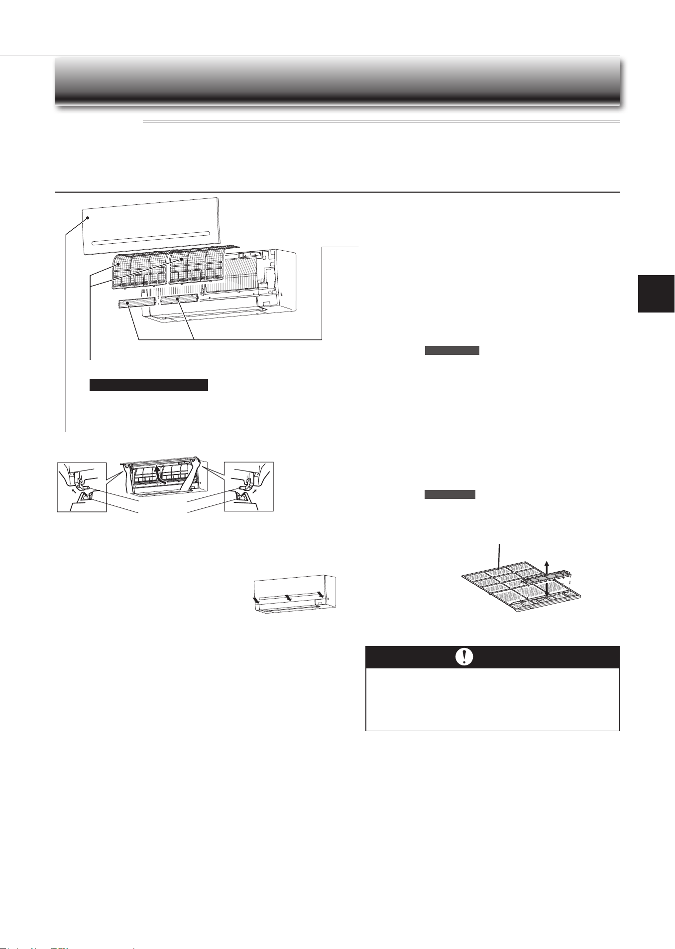
Cleaning
Air lter (Air purifying lter)
•
Clea n e very 2 w eek s
• Remove dirt by a vacuum cleaner, or rinse with water.
• After washing with water, dry it well in shade.
Front panel
Air cleaning lter
(Anti-Allergy Enzyme lter)
Every 3 mont hs:
• Remove dirt by a vacuum cleaner.
When dirt cannot be re m oved by va cuum clea ning:
•
Soakthelteranditsframeinlukewarmwaterbeforerinsingit.
•
After washing, dry it well in shade.
Installalltabsoftheairlter.
Every ye a r:
• Replaceitwithanewaircleaninglterforbestperformance.
• Parts Number
MAC-408FT-E
Hole
Hinge
Im port a nt
• Clean the lters regularly for best performance and to
reduce pow er c onsumption.
• Dirty lters cause condensation in the air conditioner
which will contribute to the growth of fungi such as
mold. It is therefore recommended to clean air lters
every 2 w e eks.
(Electrostatic anti-allergy enzyme
lter, option)
Every 3 mont hs:
• Remove dirt by a vacuum cleaner.
• Put it back to its original position, and install all tabs of the air
cleaninglter.
When dirt cannot be re m oved by va cuum clea ning:
• Soakthelteranditsframeinlukewarmwaterbeforerinsingit.
• Afterwashing,dryitwellinshade.Installalltabsoftheairlter.
Every ye a r:
• Replaceitwithanewaircleaninglterforbestperformance.
• Parts Number
MAC-2320FT
Inst ruct ions:
• Switchothepowersupplyorturnothebreakerbeforecleaning.
• Be careful not to touch the metal parts with your hands.
• Do not use benzine, thinner, polishing powder, or insecticide.
• Whendirtstandsout,washitwithkitchenneutraldetergentdilutedwithluke-
warmwatertothespeciedconcentration,thenwipeothedetergentwitha
damp towel.Use only diluted mild detergents.
• Donotuseascrubbingbrush,ahardsponge,orthelike.
• Donotsoakorrinsethehorizontalvane.
• Donotusewaterhotterthan50°C.
• Donotexposepartstodirectsunlight,heat,orretodry.
• Donotapplyexcessiveforceonthefanasitmaycausecracksorbreakage.
Pull to remove
fromtheairlter.
Attachtotheairlter
Airlter
En-13
● OPERATING INSTRUCTIONS ●
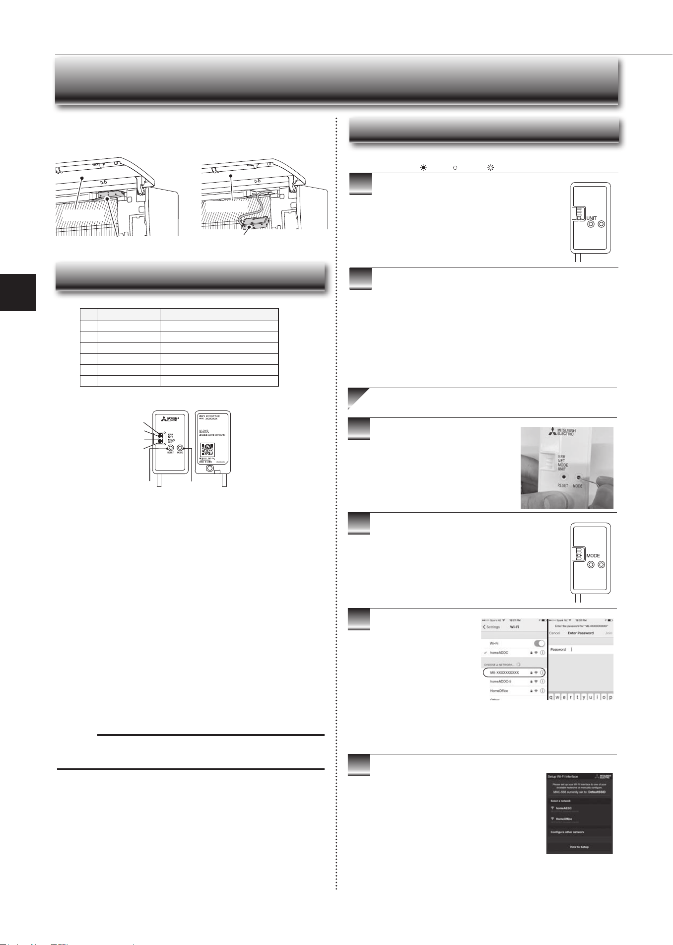
Wi-Fi Interface Seing Up (VGK Type Only)
This Wi-Fi interface, communicates the status information and controls
the commands from the server by connecting to the indoor unit.
Wi-Fi interface Wi-Fi interface
Front panel
Wi-Fi Interface Introduction
(1) Mode button
WPS-push
• Hold down the mode button for 2 seconds to start WPS-push pairing.
• When WPS-push is enabled on the Wi-Fi interface, the Mode LED starts
ashingorange(everysecond)andthepairingcanbecompletedby
enabling WPS-push on the Router.
Access Point mode
• Hold down the mode button for 7 seconds to start Access Point mode.
• When Access Point mode is enabled on the Wi-Fi interface, the Mode LED
startsashingorange(every5seconds).
• To cancel Access Point mode, hold down the mode button for 7 seconds
againandensurethattheModeLEDisnolongerashing..
Note:
WhentheWi-Fiinterfaceisresettothefactorydefault,alltheconguration
informationwillbelost.Takegreatcareinimplementingthisoperation.
(2) Reset button
• Hold down the reset button for 2 seconds to reboot the system.
• Hold down the reset button for 15 seconds to initialise the Wi-Fi interface
to the factory default.
No Item Description
1
Mode button Selects modes.
2
Reset button Resets the system and all settings.
3
ErrLED(orange) Showsthenetworkerrorstate.
4
NetLED(green) Showsthenetworkstate.
5
ModeLED(orange) Shows the Access Point mode state.
6
UnitLED(green) Shows the indoor unit state.
3
4
5
6
2 1
3
4
5
6
Information for Users
The following steps explain how to connect the Wi-Fi interface to a Router.
1
2
.
There are two options of connecting
Ensure the Wi-Fi interface is connected correctly as per
theprevioussection,‘ConnectingtheWi-Fiinterface’.
UnitLEDshouldbeashinggreenonly.
: On : Flashing : O
Key (led lights):
Download and install Wi-Fi control App to your
compatible Apple or Android smartphone/tablet
(searchterm:MitsubishiWi-FiControl).
Activate Access Point mode on your
Wi-Fi interface by using a small object
to press and hold the mode button for 7
seconds.
When Access Point mode is enabled on the Wi-Fi
interface,ModeLEDstartsashingorange(every5
seconds).
Option 1 - Access Point mode pairing
Checkthelabelontheback
of the interface for the SSID.
OpentheWi-Finetworks
screen on your smartphone/
tablet and connect to the
networkwiththesamename
astheSSID.Thenetwork
password, labelled KEY, is
just under the SSID on the
interface.
You will now be connected to
this Wi-Fi interface
Open Wi-Fi Control App and follow the ‘How to
Setup’instructionsinthe‘SetupWi-Fiinterface’
section.
If the app does not go to this section, you are
notconnectedtotheWi-Fiinterface’sAccess
Point;pleasestartprocessagain.
You can either select your available Wi-Fi
Network,ormanuallycongureaWi-FiNetwork.
Front panel
En-14
Wi-Fi Interface Seing Up (VGK Type Only)
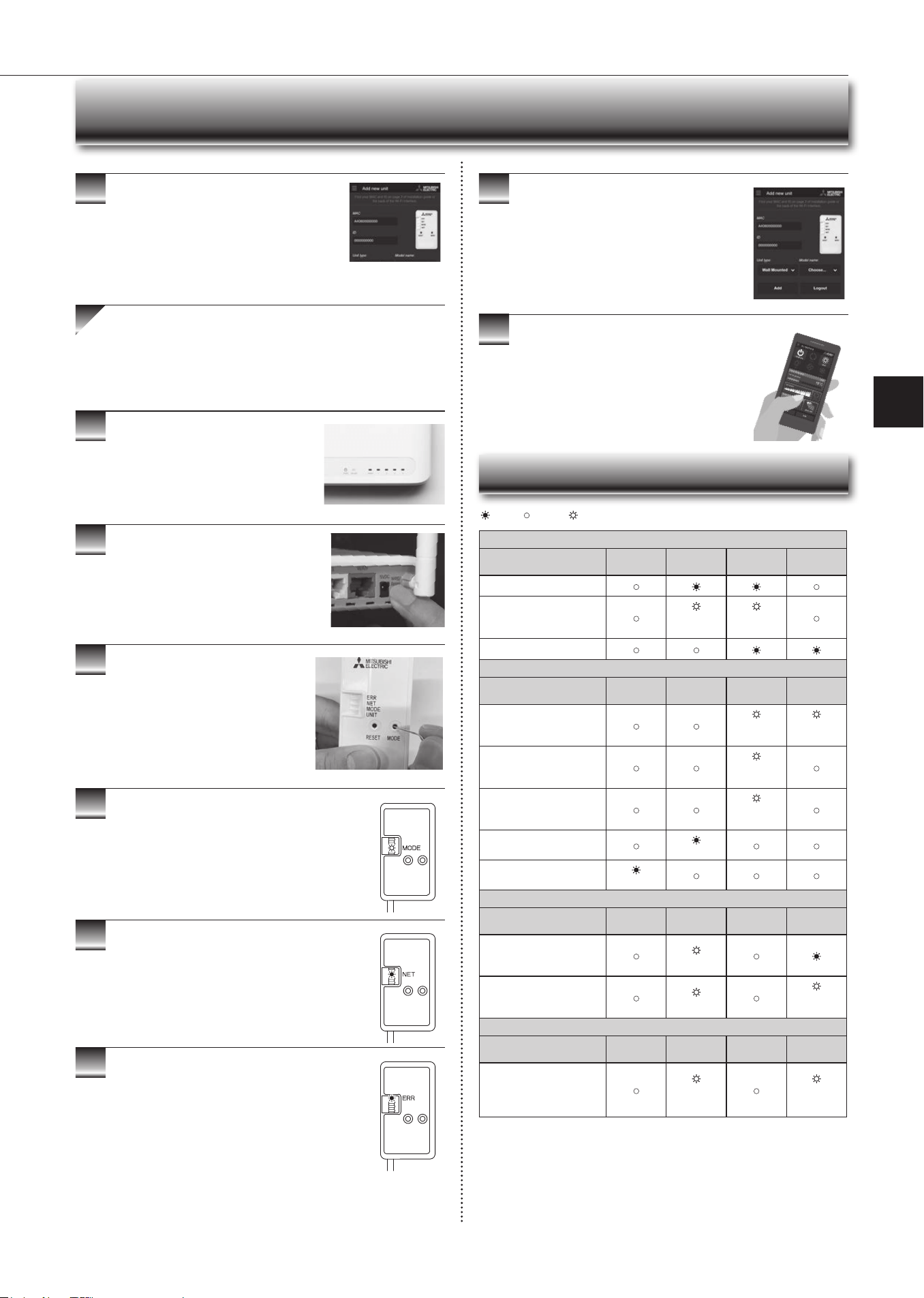
9
10
3
4
5
6
7
8
When WPS-Push is enabled on the Wi-Fi interface,
ModeLEDstartsashingorange(everysecond).
Open Wi-Fi Control App. Enter MAC and ID into
‘Addnewunit’andselect‘Add’.
Once completed, control your heat pump via Wi-Fi.
7
● Software Initialising
Description
ERR
(Orange)
NET
(Green)
MODE
(Orange)
UNIT
(Green)
Firmware updating
Firmware downloading
(every
second)
(every
second)
Reset to the factory default
● Wireless Setting
Description
ERR
(Orange)
NET
(Green)
MODE
(Orange)
UNIT
(Green)
Access Point mode
activated
(every 5
sec)
(every 5
sec)
WPS-PUSH mode activated
(every
second)
WPS-PIN mode activated
(every0.5
sec)
Pairing process via WPS
completed
(5sec)
Pairing process via WPS
failed
(5sec)
● Connection To Server In Progress
Description
ERR
(Orange)
NET
(Green)
MODE
(Orange)
UNIT
(Green)
Communicating with server,
and starting up indoor unit
communication
(*1)
Communicating with server,
and communicating with
indoor unit
(*1)
(every 5
sec)
● Normal Operation
Description
ERR
(Orange)
NET
(Green)
MODE
(Orange)
UNIT
(Green)
Communicating with server,
and communicating with
indoor unit
(every 5
sec)
(every 5
sec)
(*1)Detailsofashpattern
• Every0.5sec:Searchingforserver.
• Every second: Registering the information of the Wi-Fi interface to server.
: On : Flashing : O
Oncecompleted,theMACandIDwillbelledin
‘Addnewunit’.Select‘Add’andthencontrolyour
heat pump via Wi-Fi.
Option 2 - WPS-push pairing
• Please note: The WPS and Router reset buttons may be
similar on some Routers.
• Please exercise caution as resetting your Router will erase
networkconguration.
CheckWi-FiandWPSareenabledonyour
Router. The connection procedure varies
depending on your Router – refer to your
Router’smanualformoreinformation.
Activate WPS mode on your Router. this
will be enabled for a set period allowing
approximately 2 minutes to complete the next
step.Todoso,pleaserefertoyourRouter’s
manual.
Activate WPS on your Wi-Fi interface by
using a small object to press and hold the
mode button for 2 seconds.
When pairing process is completed on the Wi-Fi
interface, the Net LED lights up solid green for 5
seconds.
If Err LED lights up orange for 5 seconds at any stage,
theremaybeaproblem;pleasestartprocessagain.
LED Pattern
En-15
● OPERATING INSTRUCTIONS ●
Wi-Fi Interface Seing Up (VGK Type Only)
Description
ERR
(Orange)
NET
(Green)
MODE
(Orange)
UNIT
(Green)
Connection to server
established, and connection to
indoor unit failed
Connection to Router failed,
and connection to indoor unit
established
(*3)
Connection to Router failed,
and starting up indoor unit
connection
(*3)
Connection to Router failed,
and connection to indoor unit
failed
(*3)
Connection to server failed,
and connection to indoor unit
established
(*2)
Connection to server failed,
and starting up indoor unit
connection
(*2)
Connection to server failed,
and connection to indoor unit
failed
(*2)
(*2)Detailsofashpattern
• Every0.5sec:IPaddresssettingisinvalid.CheckDHCPSettingsofthe
Router,orcheckIPaddresssettingsoftheWi-Fiinterface.Ifbothsettings
are correct but still the problem persists, push reset button for more than 15
seconds to retry the pairing.
• Everysecond:DNSsettingisinvalid.CheckDNSSettingsoftheRouter,
orcheckDNSaddresssettingsoftheWi-Fiinterface.Ifbothsettingsare
correct but still the problem persists, push reset button for more than 15
seconds to retry the pairing.
• Twiceevery5sec:Notconnectedtoserver.CheckiftheRouterisonnected
to the internet.
• Once every 5 sec: Not communicating with server properly. Push reset
button for 2 seconds.
(*3)DetailswhenNETLEDiso
TheWi-FiinterfacefailedtoconnecttotheRouter.Checkthefollowing,and
pair the Wi-Fi interface.
• MakesurethatthecommunicationdistanceisnottoofarbetweentheWi-Fi
interface and the Router.
• Makesure2.4GHzisenabledondualbandRouters.
• MakesurethattheRouterusesWPA2-PSK(AES)encryption.
• MakesurethatthenumberofconnecteddevicestotheRouterdoesnot
exceed the limit.
• MakesurethatWPSisworkingontheRouter.
• MakesurethattheRouteriscompatiblewiththeWi-Fiinterface.
• IfStaticIPhasbeenset-makesureitiscorrectasperRouternetworksettings.
If a problem regarding connecting your Router and the Wi-Fi interface persists,
pleasecontactyourlocalMitsubishiElectricoce,aslistedonthebackofthis
guide. A list of compatible Routers is also available.
: On : Flashing : O
Note:
• Ensure that the Router supports the WPA2-AES encryption setting before
starting the Wi-Fi interface setup.
• The End user should read and accept the terms and conditions of the Wi-Fi
service before using this Wi-Fi interface.
• To complete connection of this Wi-Fi interface to the Wi-Fi service, the Rout-
er may be required.
• This Wi-Fi interface will not commence transmission of any operational data
from the system until the End user registers and accepts the terms and con-
ditions of the Wi-Fi service.
• This Wi-Fi interface should not be installed and connected to any Mitsubishi
Electric system which is to provide application critical cooling or heating.
• Please write down the information regarding the Wi-Fi interface setting on the
last page of this manual, when you set up this Wi-Fi interface.
• At the time of relocation or disposal, reset the Wi-Fi interface to the factory
default.
MitsubishiElectric’sWi-Fiinterfaceisdesignedforcommunicationto
MitsubishiElectric’sWi-Fiservice.ThirdpartyWi-Fiinterfacescannot
connecttoMitsubishiElectric’sWi-Fiservice.MitsubishiElectricisnot
responsibleforany(i)underperformanceofasystemoranyproduct;(ii)
systemorproductfault;or(iii)lossordamagetoanysystemorproduct;
which is caused by or arises from connection to and/or use of any third
party Wi-Fi interface or any third party Wi-Fi service with Mitsubishi Electric
equipment.
For the latest information regarding Wi-Fi Control:
NewZealandbasedenquiriespleasevisit:www.mitsubishi-electric.co.nz/wi
Australianbasedenquiriespleasevisit:www.mitsubishielectric.com.au/wi
Once registered you will be able to control your heat
pump with your smartphone, tablet or online account
using an internet connection.
(For a list of compatible devices, please visit the
MitsubishiElectricwebsite).
User Manual
A copy of the user manual, terms & conditions and
privacy policy can be downloaded at any time from the
Mitsubishi Electric website.
Mitsubishi Electric New Zealand
www.mitsubishi-electric.co.nz/wi
Phone:0800639434
Mitsubishi Electric Australia
www.mitsubishielectric.com.au/wi
Phone:1300728119
Register your heat pump(s)
ThankyouforchoosingaMitsubishiElectricHeatPumpwithWi-FiControl.
Once your Wi-Fi interface is installed, either download the app (search term:
MitsubishiWi-FiControl)orvisitourwebsitetoregisteryourheatpump(s).
*AppleandtheApplelogoaretrademarksofAppleInc.,registeredintheU.S.
andothercountries.AppStoreisaservicemarkofAppleInc.,registeredin
the U.S. and other countries.
*GooglePlayandtheGooglePlaylogoaretrademarksofGoogleInc.
Troubleshooting
Mitsubishi Electric Wi-Fi Heat Pump Control
En-16
Even if these items are checked, when the unit does not recover from the
trouble, stop using the air conditioner and consult your dealer.
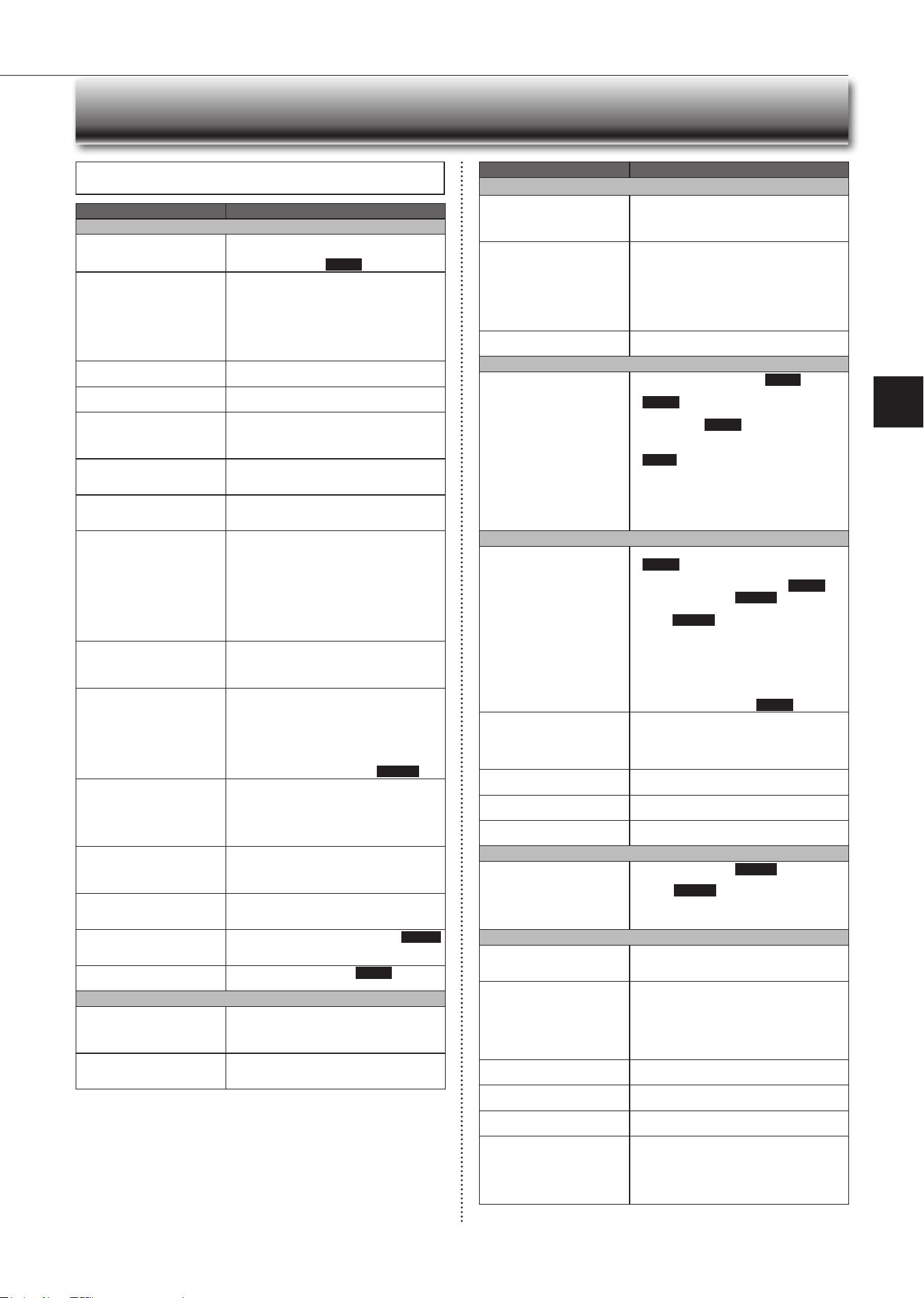
When You Think That Trouble Has Occurred
Symptom Explanation & Check Points
Indoor Unit
The unit cannot be operated.
• Isthebreakerturnedon?
• Isthepowersupplyplugconnected?
• Istheontimerset?
Page 9
The horizontal vane does not
move.
• Are the horizontal vane and the vertical vane
installedcorrectly?
• Isthefanguarddeformed?
• Whenthebreakeristurnedon,thehorizontal
vanes’positionwillberesetinaboutaminute.
After the reset has completed, the normal hori-
zontalvanes’operationresumes.Thesameis
true in the emergency cooling operation.
The unit cannot be operated for
about3minuteswhenrestarted.
• This protects the unit according to instructions
from the microprocessor. Please wait.
Mist is discharged from the air
outlet of the indoor unit.
•
The cool air from the unit rapidly cools moisture
in the air inside the room, and it turns into mist.
Whitesmokeisdischargedfrom
the air inlet of the indoor unit.
• When the heating operation starts after the
defrosting operation, vapor generated from the
condensationontheheatexchangerlookslike
whitesmoke.
The swing operation of the horizon-
tal vane is suspended for a while,
then restarted.
• This is for the swing operation of the horizontal
vane to be performed normally.
When swing is selected in cool/
dry/fan mode, the lower horizon-
tal vane does not move.
• It is normal that the lower horizontal vane does
not move when swing is selected in cool/dry/fan
mode.
Theairowdirectionchanges
during operation.
The direction of the horizontal
vane cannot be adjusted with
the remote controller.
• When the unit is operated in cool or dry mode,
if the operation continues with air blowing down
for0.5To1hour,thedirectionoftheairowis
automatically set to upward position to prevent
water from condensing and dripping.
• Intheheatingoperation,iftheairowtempera-
ture is too low or when defrosting is being done,
the horizontal vane is automatically set to hori-
zontal position. Also the fan speed decreases
or the fan stops.
The operation stops for about
10minutesintheheating
operation.
• Outdoor unit is in defrost.
Since this is completed in max. 10 minutes,
please wait. (When the outside temperature is
toolowandhumidityistoohigh,frostisformed.)
The unit starts operation by
itself when the main power is
turned on, though it isn't oper-
ated with the remote controller.
• These models are equipped with an auto
restart function. When the main power is
turned o without stopping the unit with the
remote controller and is turned on again, the
unit starts operation automatically in the same
mode as the one set with the remote control-
ler just beforetheshutoof the main power.
Refer to “Auto restart function”.
Page 11
The two horizontal vanes touch
each other. The horizontal
vanes are in an abnormal posi-
tion. The horizontal vanes do
not return to the correct “close
position”.
Perform one of the following:
•
Turnoandonthebreaker.Makesurethehori-
zontal vanes move to the correct “close position”.
• Start and stop the emergency cooling operation
andmakesurethehorizontalvanesmovetothe
correct “close position”.
The indoor unit discolors over
time.
• Althoughplasticturnsyellowduetotheinuence
of some factors such as ultraviolet light and
temperature,thishasnoeectontheproduct
functions.
The ceiling and the walls around
the indoor unit have smudges.
• It is because the ceiling and the walls get dust
in the air due to air circulation by the air condi-
tioner.
Waterleaksfromtheindoor
unit.
• Isthefrontpanelclosedaccurately? Page 12
• Doeswaterowsmoothlyfromtheedgeofthe
drainhose?
The operation indicator lamp is
dim. The unit does not beep.
• IstheNIGHTMODEset? Page 9
Multi System
The indoor unit which is not
operating becomes warm and a
sound,similartowaterowing,
is heard from the unit.
• Asmallamountofrefrigerantcontinuestoow
into the indoor unit even though it is not operat-
ing.
When heating operation is
selected, operation does not
start right away.
• When operation is started during defrosting of
outdoorunitisdone,ittakesafewminutes(max.
10minutes)toblowoutwarmair.
Symptom Explanation & Check Points
Outdoor Unit
The fan of the outdoor unit does
not rotate even though the com-
pressor is running. Even if the
fan starts to rotate, it stops soon.
• When the outside temperature is low during
cooling operation, the fan operates intermittently
tomaintainsucientcoolingcapacity.
Waterleaksfromtheoutdoor
unit.
• During cool and dry mode operations, pipe or
pipe connecting sections are cooled and this
causes water to condense.
• In the heating operation, water condensed on
the heat exchanger drips down.
• In the heating operation, the defrosting operation
makesiceformingontheoutdoorunitmeltand
drip down.
Whitesmokeisdischargedfrom
the outdoor unit.
• In the heating operation, vapor generated by the
defrostingoperationlookslikewhitesmoke.
Remote Controller
The display on the remote
controller does not appear or it
is dim. The indoor unit does not
respond to the remote control
signal.
• Arethebatteriesexhausted? Page 5
• Is the polarity (+, -) of the batteries correct?
Page 5
• Did you press the reset button after replacing
thebatteries?
Page 5
• Isthesettingofmultipleindoorunits’installation
the same as before replacing the batteries?
Page 5
• Are any buttons on the remote controller of other
electricappliancesbeingpressed?
• The indoor unit may not receive the signal well
depending on the condition in the room. Get
close to the indoor unit and operate the remote
controller.
Does Not Cool or Heat
The room cannot be cooled or
heatedsuciently.
• Isthetemperaturesettingappropriate?
Page 6
• Isthefansettingappropriate?Pleasechange
fan speed to High or Super High.
Page 7
• Aretheltersclean? Page 12
•
Is the fan or heat exchanger of the indoor unit
clean?
Page 12
• Arethereanyobstaclesblockingtheairinletor
outletoftheindoororoutdoorunit?
• Isawindowordooropen?
• Itmaytakeacertaintimetoreachthesetting
temperature or may not reach that depending on
the size of the room, the ambient temperature,
andthelike.
• IstheNIGHTMODEset?
Page 9
The room cannot be cooled
suciently.
• Whenaventilationfanoragascookerisused
in a room, the cooling load increases, resulting
inaninsucientcoolingeect.
• When the outside temperature is high, the cool-
ingeectmaynotbesucient.
The room cannot be heated
suciently.
• When the outside temperature is low, the heat-
ingeectmaynotbesucient.
Air does not blow out soon in
the heating operation.
• Please wait as the unit is preparing to blow out
warm air.
Poor cooling or heating perfor-
mance.
• Do you have an arrangement with your electric
companyforDemandResponse?
Airow
The air from the indoor unit
smells strange.
• Aretheltersclean? Page 12
• Is the fan or heat exchanger of the indoor unit
clean? Page 12
• Theunitmaysuckinanodoradheringtothe
wall, carpet, furniture, cloth, etc. and blow it out
with the air.
Sound
Crackingsoundisheard. • This sound is generated by the expansion/
contraction of the front panel, etc. due to change
in temperature.
“Burbling” sound is heard. • This sound is heard when the outside air is
absorbed from the drain hose by turning on the
rangehoodortheventilationfan,makingwater
owinginthedrainhosetospoutout.
This sound is also heard when the outside air
blows into the drain hose in case the outside
wind is strong.
Mechanical sound is heard from
the indoor unit.
• Thisistheswitchingsoundinturningon/othe
fan or the compressor.
Thesoundofwaterowingis
heard.
• This is the sound of refrigerant or condensed
waterowingintheunit.
Hissing sound is sometimes
heard.
• Thisisthesoundwhentheowofrefrigerant
inside the unit is changed.
Heating operation stops and the
sound is heard.
• The outdoor unit is defrosting.
• Heating operation starts after the frosy on the
outdoorunithasbeenremoved.Thiscantake
about2to10minutes.
• Crackingsound,Soundofwaterowing,Hiss-
ing sound and Whistling sound are heard.
En-17
● OPERATING INSTRUCTIONS ●
In the following cases, stop using the air conditioner and consult your dealer.
• Whenwaterleaksordripsfromtheindoorunit.
• Whentheoperationindicatorlampblinks.
• Whenthebreakertripsfrequently.
• The remote control signal is not received in a room where an electronic on/
otypeuorescentlamp(inverter-typeuorescentlamp,etc.)isused.
• Operation of the air conditioner interferes with radio or TV reception. An ampli-
ermayberequiredfortheaecteddevice.
• When an abnormal sound is heard.
• Whenanyrefrigerantleakageisfound.
1
Operate by cool mode with the highest temperature set
orfanmodefor3to4hours.
Page 6
• This dries the inside of the unit.
• Moisture in the air conditioner contributes to favorable conditions for
growth of fungi, such as mold.
2
Press
to stop the operation.
3
Turnothebreakerand/ordisconnectthepowersup-
ply plug.
4
Remove all batteries from the remote controller.
When using the air conditioner again:
1
Cleantheairlter. Page 12
2
Checkthattheairinletandoutletoftheindoorand
outdoorunitsarenotblocked.
3
Checkthattheearthisconnectedcorrectly.
4
Refer to the “PREPARATION BEFORE OPERATION”,
and follow the instructions. Page 5
When the Air Conditioner Is Not Going to
Be Used For a Long Time
When You Think That Trouble Has
Occurred
Symptom Explanation & Check Points
Timer
Weeklytimerdoesnotoperate
according to settings.
• Istheon/otimerset? Page 9
• Transmitthesettinginformationoftheweekly
timer to the indoor unit again. When the informa-
tion is successfully received, a long beep will
sound from the indoor unit. If information fails to
bereceived,3shortbeepswillbeheard.Ensure
information is successfully received.
Page10
• When a power failure occurs and the main
power turnso,theindoorunitbuilt-inclockwill
beincorrect.Asaresult,theweeklytimermay
notworknormally.
Be sure to place the remote controller where
the signal can be received by the indoor unit.
Page 5
The unit starts/stops the opera-
tion by itself.
• Istheweeklytimerset?Page10
Others
Thealuminumnontheedgeof
the heat exchanger is discolored
as if it is burnt.
• This is the coating resin discolored due to weld-
ing heat when the heat exchanger was being
produced.
• The operation of the air conditioner is not the
cause of the discoloration.
• Itaectsneithertheperformanceoftheheat
exchanger nor the use of the air conditioner.
En-18
Installation place
Avoid installing the air conditioner in the following places.
• Where there is much machine oil.
• Salty places such as the seaside.
• Wheresuldegasisgeneratedsuchashotspring,sewage,wastewater.
• Whereoilissplashedorwheretheareaislledwithoilysmoke(suchascook-
ing areas and factories, in which the properties of plastic could be changed
anddamaged).
• Where there is high-frequency or wireless equipment.
• Wheretheairfromtheoutdoorunitairoutletisblocked.
• Where the operation sound or air from the outdoor unit bothers the house next
door.
• Themountingheightofindoorunit1.8mto2.3misrecommended.Ifitis
impossible, please consult your dealer.
• Donotoperatetheairconditionerduringinteriorconstructionandnishing
work,orwhilewaxingtheoor.Beforeoperatingtheairconditioner,ventilate
theroomwellaftersuchworkisperformed.Otherwise,itmaycausevolatile
elementstoadhereinsidetheairconditioner,resultinginwaterleakageor
scattering of dew.
For Wi-Fi interface
• Theindoorunitmustbeinstalledinroomswhichexceedtheoorspacespeci-
ed.Pleaseconsultyourdealer.
• Do not use the Wi-Fi interface nearby the medical electrical equipment or peo-
plewhohaveamedicaldevicesuchasacardiacpacemakeroranimplantable
cardioverter-debrillator.
It can cause an accident due to malfunctions of the medical equipment or
device.
• This equipment should be installed and operated with a minimum distance of
20cmbetweenthedeviceandtheuserorbystanders.
• Do not use the Wi-Fi interface nearby other wireless devices, microwaves,
cordless phones, or facsimiles.
Electrical work
• Provide an exclusive circuit for the power supply of the air conditioner.
• Besuretoobservethebreakercapacity.
If you have any questions, consult your dealer.
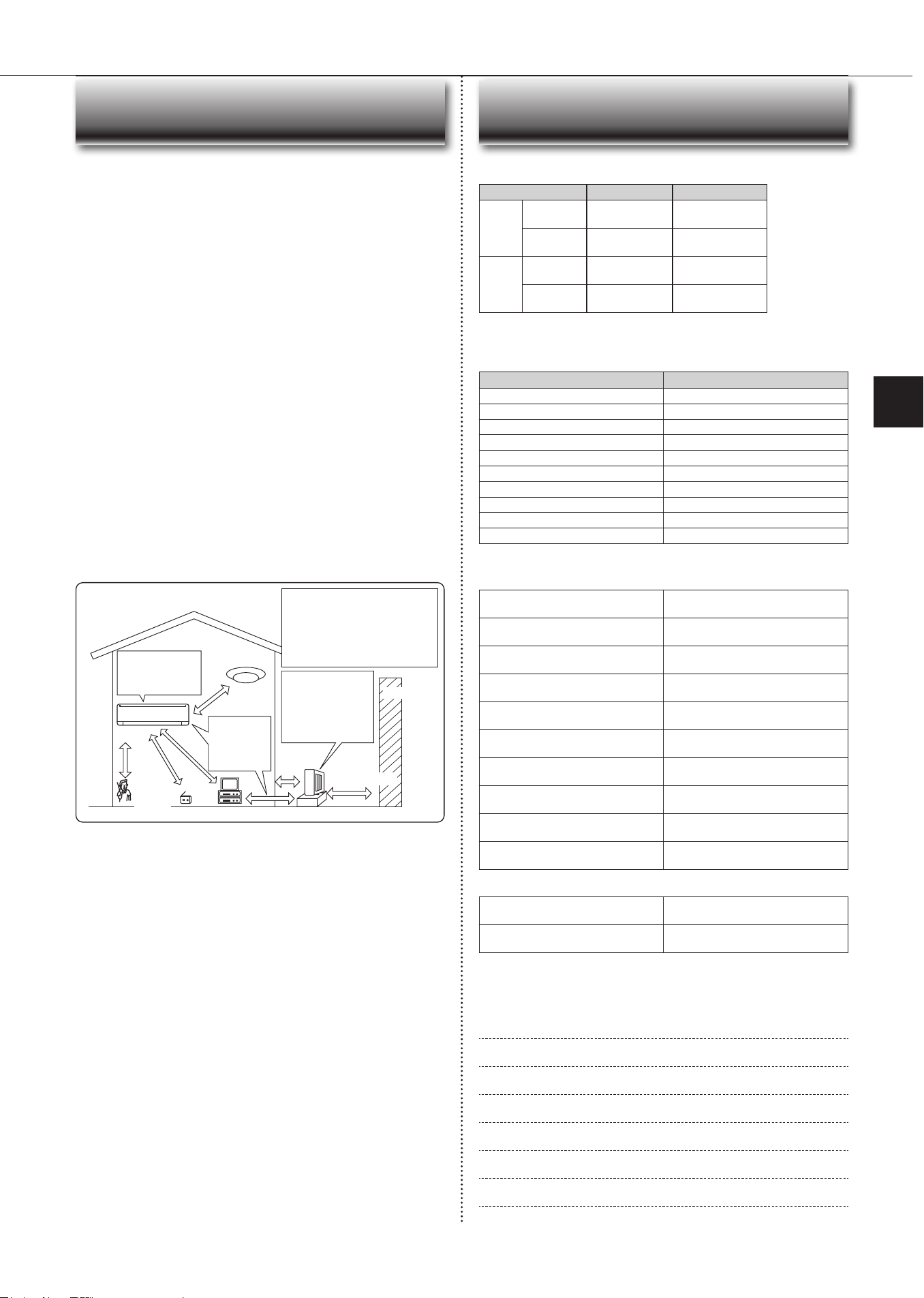
Installation Place and
Electrical Work
Topreventtheeects
ofauorescentlamp,
keepasfarapartas
possible.
wall, etc.
Inverter-type
uorescentlamp
Keep a space
to prevent
the picture
distortion or
the noise.
1 m
or
more
Radio
100
mmor
more
TV
Cordless
phone or
Portable
phone
3mormore
1 m
or more
The installation location of the outdoor
unitshould be atleast 3m awayfrom
the antennas for TV sets, radios, etc. In
areaswherethereceptionisweak,pro-
vide greater space between the outdoor
unit and the antenna of the aected
device if operation of the air conditioner
interferes with radio or TV reception.
200mmormore
For the optimum ef-
ciency
andtoextend
the life time of using,
the outdoor unit
should be installed in
a well-ventilated dry
place.
Specications
Wi-Fi interface setting information
Indoor unit model name
Indoor unit serial number
Outdoor unit model name
Outdoor unit serial number
Wi-FiinterfaceMACaddress(MAC)
Wi-Fiinterfaceserialnumber(ID)
Wi-FiinterfaceSSID(SSID)
Wi-FiinterfaceKEY(KEY)
System commissioning date
Wi-Fi interface installation date
Installer contact details
Name
Telephone number
MEMO
Indoor Outdoor
Cooling
Upper limit
32°CDB
23°CWB
46°CDB
—
Lower limit
21°CDB
15°CWB
-10°CDB
—
Heating
Upper limit
27°CDB
—
24°CDB
18°CWB
Lower limit
20°CDB
—
-15°CDB
-16°CWB
Guaranteed operating range
DB : Dry Bulb
WB : Wet Bulb
Wi-Fi interface
Model MAC-578IF2-E
Input Voltage DC12.7V(fromindoorunit)
Power consumption MAX 2 W
SizeH×W×D(mm) 73.5×41.5×18.5
Weight(g) 46(includingcable)
Transmitterpowerlevel(MAX) 20dBm@IEEE802.11b
RF channel 1ch~13ch(2412~2472MHz)
Radio protocol IEEE802.11b/g/n(20)
Encryption AES
Authentication WPA2-PSK
Software Version XX.00

HEADOFFICE:TOKYOBUILDING,2-7-3,MARUNOUCHI,CHIYODA-KU,TOKYO100-8310,JAPAN
VG79N348H02