SERVICE MANUAL
CONTENTS
1. TECHNICAL CHANGES ··································· 3
2. PART NAMES AND FUNCTIONS ····················· 6
3. SPECIFICATION ················································ 7
4. OUTLINES AND DIMENSIONS ·······················11
5. WIRING DIAGRAM ·········································· 12
6. REFRIGERANT SYSTEM DIAGRAM ············· 20
7. DATA ································································ 23
8. ACTUATOR CONTROL ··································· 37
9. SERVICE FUNCTIONS ··································· 38
10. TROUBLESHOOTING ····································· 38
11. DISASSEMBLY INSTRUCTIONS ···················· 65
12. PARTS LIST ····················································· 72
12-1. PARTS LIST ··········································· 72
12-2. RoHS PARTS LIST ································ 78
13. OPTIONAL PARTS ······················ BACK COVER
Models
MUZ-A09NA,-
1
,-
U1
,-
U2
MUZ-A12NA,-
U1
MUZ-A15NA,-
U1
MUZ-A17NA,-
U1
MUZ-A24NA,-
1
,-
U1
,-
U2
MUY-A15NA
MUY-A17NA
MUY-A24NA
,-
1
MUZ-GA24NA,-
U1
MUY-GA24NA
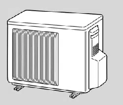
SPLIT-TYPE AIR CONDITIONERS
OUTDOOR UNIT
Indoor unit service manual
MSZ-A•NA Series (OB450)
MSZ-GA•NA Series (OB450)
MUZ-A09/12/15/17NA
MUY-A15/17NA
NOTE:
RoHS compliant products have <G> mark on the spec name plate.
For servicing of RoHS compliant products, refer to the PARTS LIST
(RoHS compliant).
TM
HFC
utilized
R410A
No. OB451
REVISED EDITION-G
Please void OB451 REVISED EDITION-F.
Revision G:
• Errors in TROUBLESHOOTING have been
corrected.
2
Revision A:
• MUZ-A09NA -
U2
and MUZ-A09NA -
1
have been added.
Revision B:
• 10-5. ”Check of outdoor thermistors” has been corrected.
Revision C:
• 10-6. ”Test point diagram and voltage” has been corrected.
10-6.3. ”Outdoor electronic control P.C. board”, the chart of thermistor has been corrected.
Revision D:
• MUZ-A24NA -
1
, MUZ-A24NA -
U2
and MUY-A24NA -
1
have been added.
Revision E:
• MUZ-GA24NA and MUY-GA24NA
have been added.
Revision F:
• The fan guard for MUZ-A24NA, -
1
, -
U1
, -
U2
and MUZ-GA24NA, -
U1
has been changed.
Use the speci¿ ed refrigerant only
Never use any refrigerant other than that specified.
Doing so may cause a burst, an explosion, or fire when the unit is being used, serviced, or disposed of.
Correct refrigerant is specified in the manuals and on the spec labels provided with our products.
We will not be held responsible for mechanical failure, system malfunction, unit breakdown or accidents caused by
failure to follow the instructions.
Revision G:
• Errors in TROUBLESHOOTING have been corrected.

3
MUZ09UN ĺ MUZ-A09NA MUZ12UN ĺ MUZ-A12NA
MUH15TN ĺ MUZ-A15NA MUH17TN ĺ MUZ-A17NA
MUH24WN ĺ MUZ-A24NA
MU15TN ĺ MUY-A15NA MU17TN ĺ MUY-A17NA
MU24WN ĺ MUY-A24NA
1. Outdoor unit model has been changed.
2. Control method between indoor and outdoor unit has been changed.
3. Refrigerant has been changed. (R22 ĺ R410A)
4. Fan motor has been changed. (AC ĺ DC)
5. Compressor has been changed. (AC ĺ DC)
MUZ-A09NA ĺ MUZ-A09NA -
1
MUZ-A09NA -
U1
ĺ MUZ-A09NA -
U2
1. Refrigerant system diagram has been changed.
MUZ-A24NA ĺ MUZ-A24NA -
1
MUZ-A24NA -
U1
ĺ MUZ-A24NA -
U2
MUY-A24NA ĺ MUY-A24NA -
1
1. Wiring diagram has been changed.
MUZ-A24NA -
1
ĺ MUZ-GA24NA
MUZ-A24NA -
U2
ĺ MUZ-GA24NA -
U1
MUY-A24NA -
1
ĺ MUY-GA24NA
1. Compressor has been changed. (SNB130FPDH ĺ SNB130FQBH)
2. Wiring diagram has been changed.
3. Fan motor has been changed.
4. ELECTRONIC CONTROL P.C. Board has been changed.
1
TECHNICAL CHANGES
4
INFORMATION FOR THE AIR CONDITIONER WITH R410A REFRIGERANT
• This room air conditioner adopts HFC refrigerant (R410A) which never destroys the ozone layer.
• Pay particular attention to the following points, though the basic installation procedure is same as that for R22 air condition-
ers.
As R410A has working pressure approximate 1.6 times as high as that of R22, some special tools and piping parts/materials
are required. Refer to the table below.
Take sufficient care not to allow water and other contaminations to enter the R410A refrigerant during storage and installa-
tion, since it is more susceptible to contaminations than R22.
For refrigerant piping, use clean, pressure-proof parts/materials specifically designed for R410A. (Refer to 2. Refrigerant pip-
ing.)
Composition change may occur in R410A since it is a mixed refrigerant. When charging, charge liquid refrigerant to prevent
composition change.
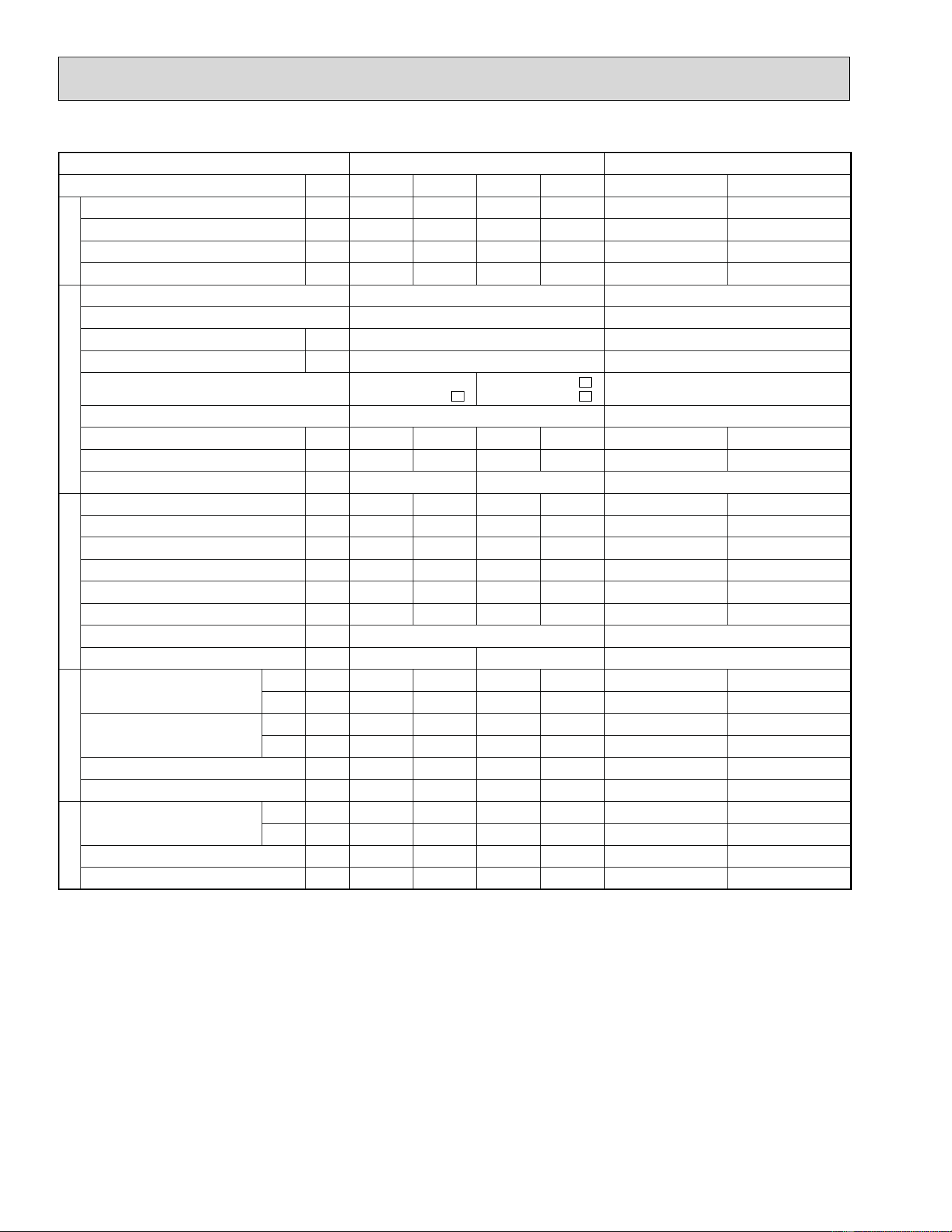
New refrigerant Previous refrigerant
Refrigerant
Refrigerant R410A R22
Composition (Ratio) HFC-32: HFC-125 (50%: 50%) R22 (100%)
Refrigerant handling Pseudo-azeotropic refrigerant Single refrigerant
Chlorine Not included Included
Safety group (ASHRAE) A1 / A1 A1
Molecular weight 72.6 86.5
Boiling point (°F) -60.5 -41.4
Steam pressure [77°F] (PSIG) 225.82 136.34
Saturated steam density [77°F] (lb./ft.
3
) 3.995 2.772
Combustibility Non combustible Non combustible
ODP
1 0 0.055
GWP
2 1730 1700
Refrigerant charge method From liquid phase in cylinder Gas phase
Additional charge on leakage Possible Possible
Refrigeration oil
Kind Incompatible oil Compatible oil
Color None Light yellow
Smell None None
1: Ozone Depletion Potential: based on CFC-11
2: Global Warming Potential: based on CO2
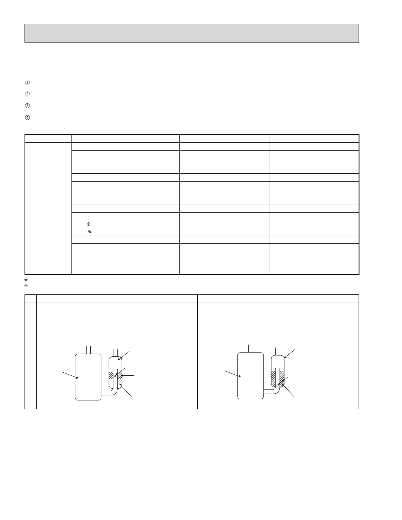
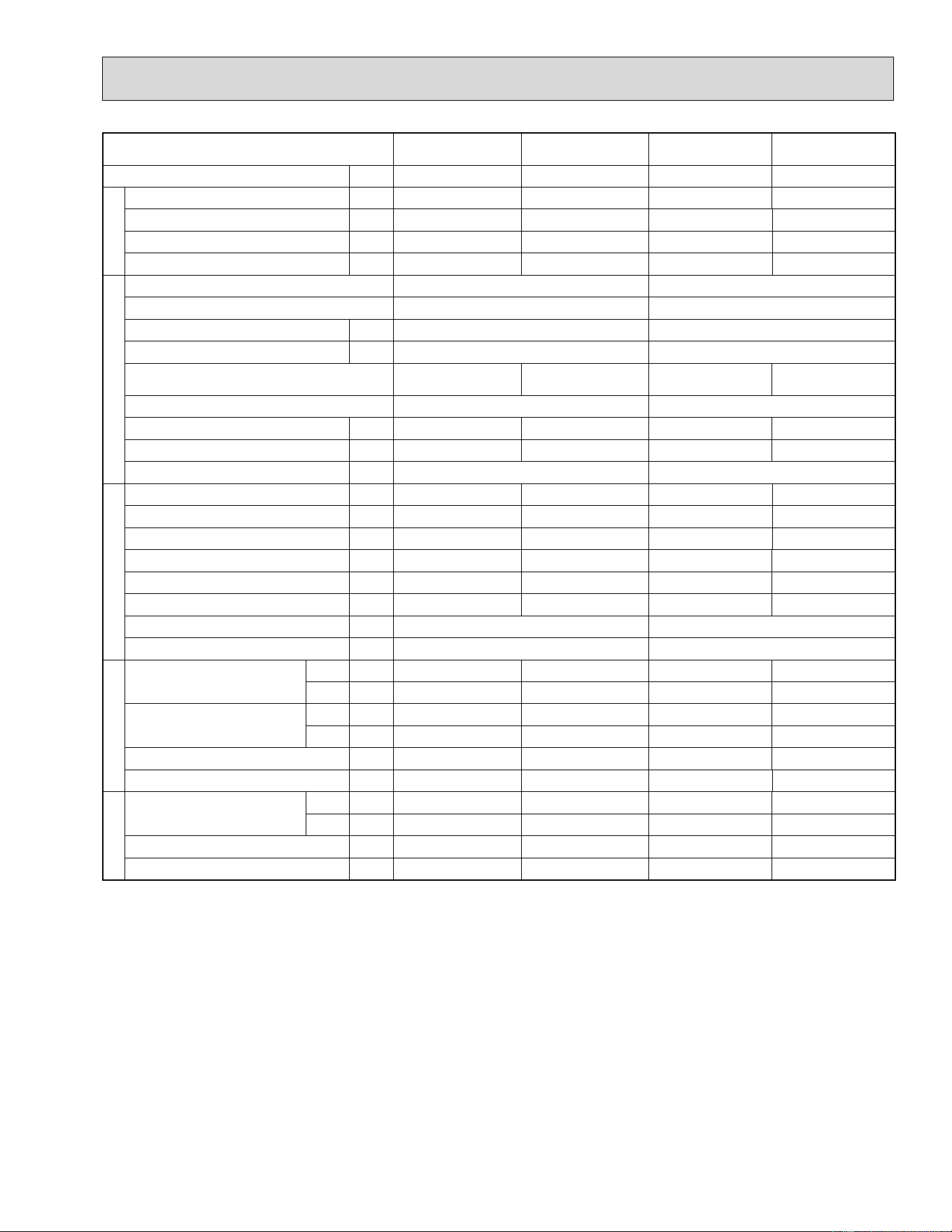
New Specification Current Specification
Compressor
The incompatible refrigeration oil easily separates from
refrigerant and is in the upper layer inside the suction
mufÀ er.
Raising position of the oil back hole enables to back the
refrigeration oil of the upper layer to flow back to the
compressor.
Since refrigerant and refrigeration oil are compatible with
each other, refrigeration oil goes back to the compressor
through the lower position oil back hole.
Compressor
Suction muffler
Oil back hole
refrigeration oil
Refrigerant
Compressor
Suction muffler
Oil back hole
Refrigeration oil /Refrigerant
5
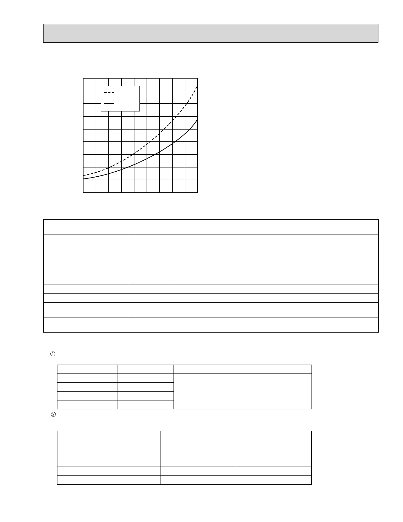
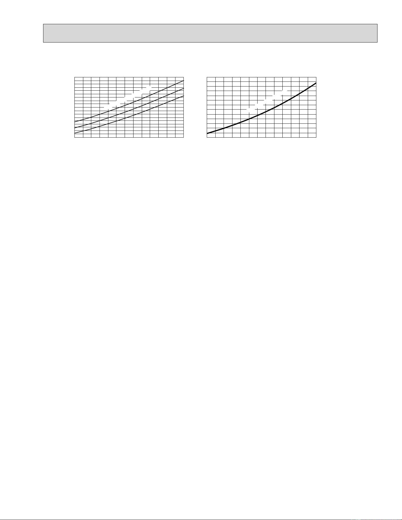
-22 -4 14 32 50 68
86
104 122 140
-73
0
73
145
218
290
363
435
508
580
(PSIG)
R410A
R22
Conversion chart of refrigerant temperature and pressure
Saturated liquid pressure
(°F)
1. Tools dedicated for the air conditioner with R410A refrigerant
The following tools are required for R410A refrigerant. Some R22 tools can be substituted for R410A tools.
R410A tools
Can R22 tools
be used?
Description
Gauge manifold No
R410A has high pressures beyond the measurement range of existing gaug-
es.
Charge hose No Hose material have been changed to improve the pressure resistance.
Gas leak detector No Dedicated for HFC refrigerant.
Torque wrench
Yes 1/4 in. and 3/8 in.
No 1/2 in. and 5/8 in.
Flare tool Yes Clamp bar hole has been enlarged to reinforce the spring strength in the tool.
Flare gauge New Provided for flaring work (to be used with R22 flare tool).
Vacuum pump adapter
New
Provided to prevent the back flow of oil. This adapter enables you to use vac-
uum pumps.
Electronic scale for refrigerant
charging
New
It is difficult to measure R410A with a charging cylinder because the refriger-
ant bubbles due to high pressure and high-speed vaporization
No: Not Substitutable for R410A Yes: Substitutable for R410A
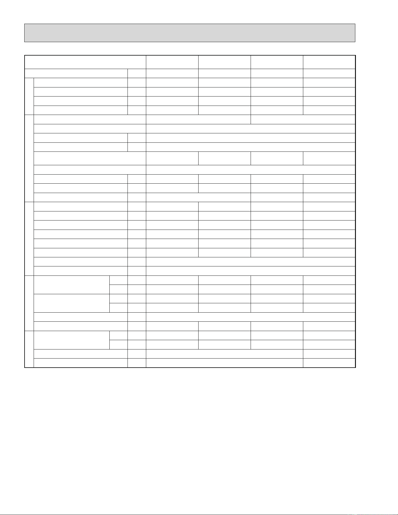
2. Refrigerant piping
Specifications
Use the copper or copper-alloy seamless pipes for refrigerant that meet the following specifications.
Outside diameter (in.) Wall thickness (in.) Insulation material
1/4 0.0315
Heat resisting foam plastic Specific gravity 0.045
Thickness 0.315 in.
3/8 0.0315
1/2 0.0315
5/8 0.0394
Flaring work and flare nut
Flaring work for R410A pipe differs from that for R22 pipe.
For details of flaring work, refer to Installation manual “FLARING WORK”.
Pipe diameter (in.)
Dimension of flare nut mm (in.)
R410A R22
1/4 17 (11/16) 17 (11/16)
3/8 22 (7/8) 22 (7/8)
1/2 26 (1-1/32) 24 (15/16)
5/8 29 (1-5/32) 27 (1-1/16)
6
3. Refrigerant oil
Apply the special refrigeration oil (accessories: packed with indoor unit) to the flare and the union seat surfaces.
4. Air purge
• Do not discharge the refrigerant into the atmosphere.
Take care not to discharge refrigerant into the atmosphere during installation, reinstallation, or repairs to the refrigerant cir-
cuit.
• Use the vacuum pump for air purging for the purpose of environmental protection.
5. Additional charge
For additional charging, charge the refrigerant from liquid phase of the gas cylinder.
If the refrigerant is charged from the gas phase, composition change may occur in the refrigerant inside the cylinder and
the outdoor unit. In this case, capacity of the refrigeration cycle decreases or normal operation can be impossible. However,
charging the liquid refrigerant all at once may cause the compressor to be locked. Thus, charge the refrigerant slowly.
Electronic scale for refrigerant charging
Outdoor unit
Refrigerant gas
cylinder
operating valve
Refrigerant gas cylinder
for R410A with siphon
Refrigerant (liquid)
Service port
Gauge manifold
valve (for R410A)
Union
Liquid pipe
Gas pipe
Stop valve
Indoor unit
Charge hose (for R410A)
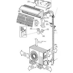
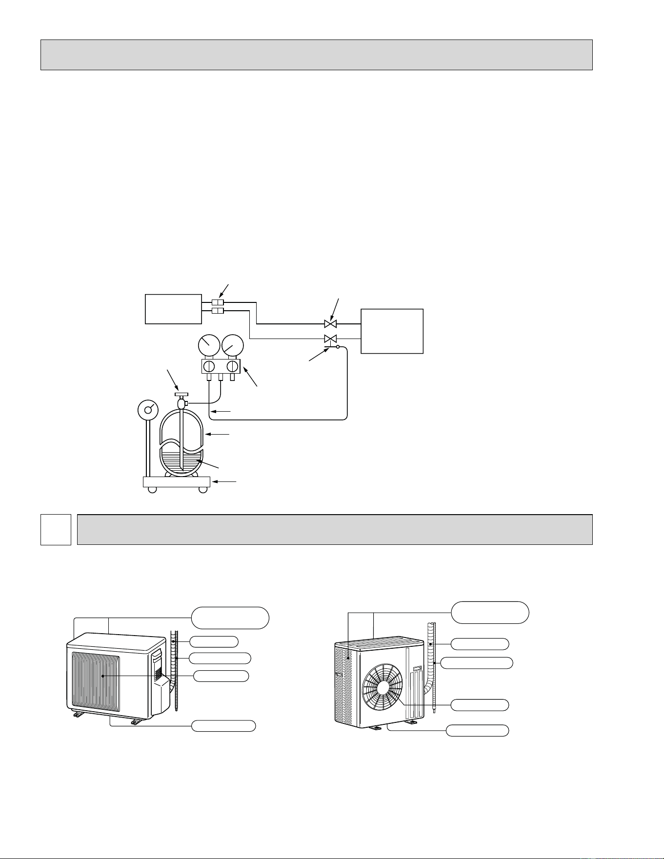
PART NAMES AND FUNCTIONS
2
Air outlet
Drain outlet
Piping
Drain hose
Air inlet
(back and side)
MUZ-A09NA MUZ-A15NA MUY-A15NA
MUZ-A12NA MUZ-A17NA MUY-A17NA
MUZ-A24NA MUY-A24NA
MUZ-GA24NA MUY-GA24NA
Piping
Air outlet
Drain hose
Drain outlet
Air inlet
(back and side)
7
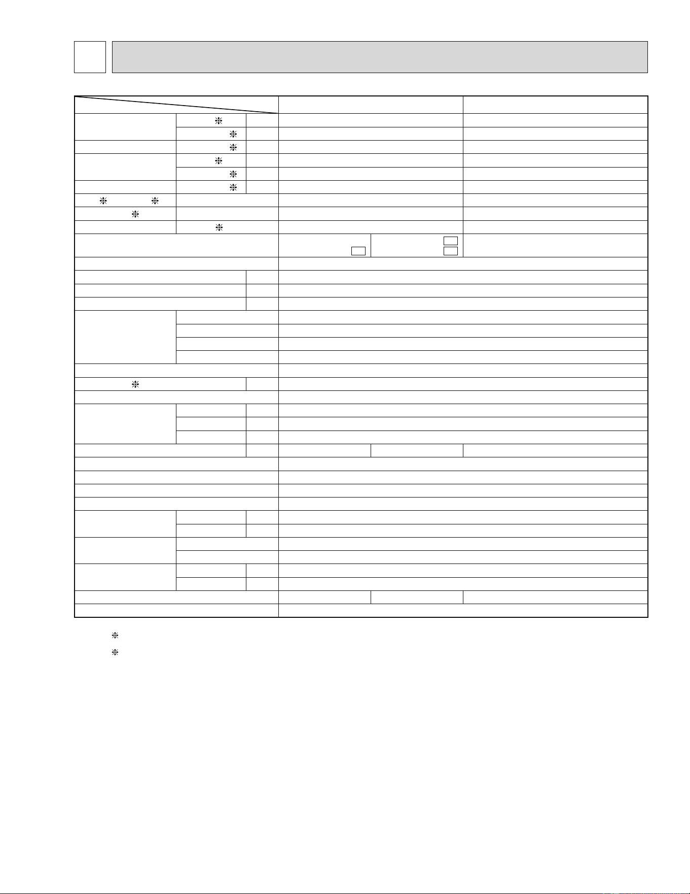
Item Model MSZ-A09NA MSZ-A12NA
Capacity
Rated (Minimum-Maximum)
Cooling
1 Btu/h 9,000 (5,500-9,000) 12,000 (5,700-12,000)
Heating 47
1 Btu/h 10,900 (5,200-12,600) 13,600 (5,200-13,600)
Capacity Heating 17 2 Btu/h 7,700 8,300
Power consumption
Rated (Minimum-Maximum)
Cooling 1 W 690 (390-690) 1,170 (395-1,170)
Heating 47 1 W 860 (350-1,100) 1,160 (350-1,160)
Power consumption Heating 17
2 W 880 930
EER 1 [SEER] 3 Cooling 13.0 [17.0] 10.3 [17.0]
HSPF IV(V) 4 Heating 8.2 (7.1) 8.2 (7.1)
COP Heating 1 3.71 3.44
Outdoor unit model
MUZ-A09NA
MUZ-A09NA -
U1
MUZ-A09NA -
1
MUZ-A09NA -
U2
MUZ-A12NA
Power supply V , phase , Hz 208/230, 1, 60
Max. fuse size (time delay) A 15
Min. circuit ampacity A 12
Fan motor F.L.A 0.52
Compressor
Model KNB092FPAH
Winding resistance (at 68ÛF)
0.49
R.L.A 7.8
L.R.A 9.2
Refrigerant control Liner expansion valve
Sound level 1 dB(A) 48
Defrost method Reverse cycle
Dimensions
W in. 31-1/2
D in. 11-1/4
H in. 21-5/8
Weight Ib. 82 75 82
External ¿ nish Munsell 3Y 7.8/1.1
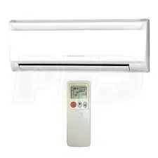
Remote controller Wireless type
Control voltage (by built-in transformer) 12 - 24 VDC
Refrigerant piping Not supplied
Refrigerant pipe size
(Min. wall thickness)
Liquid in. 1/4 (0.0315)
Gas in. 3/8 (0.0315)
Connection method
Indoor Flared
Outdoor Flared
Between the indoor &
outdoor units
Height difference
ft. 40
Piping length ft. 65
Refrigerant charge (R410A) 2 lb. 5 oz. 2 lb. 2 lb. 5 oz.
Refrigeration oil (Model) NEO22
NOTE: Test conditions are based on ARI 210/240.
1: Rating conditions (Cooling) — Indoor: 80ÛFDB, 67ÛFWB, Outdoor: 95ÛFDB, (75ÛFWB) Rated frequency
(Heating) — Indoor: 70ÛFDB, 60ÛFWB, Outdoor: 47ÛFDB, 43ÛFWB Rated frequency
2: (Heating) — Indoor: 70ÛFDB, 60ÛFWB, Outdoor: 17ÛFDB, 15ÛFWB Maximum frequency
3
SPECIFICATION
8
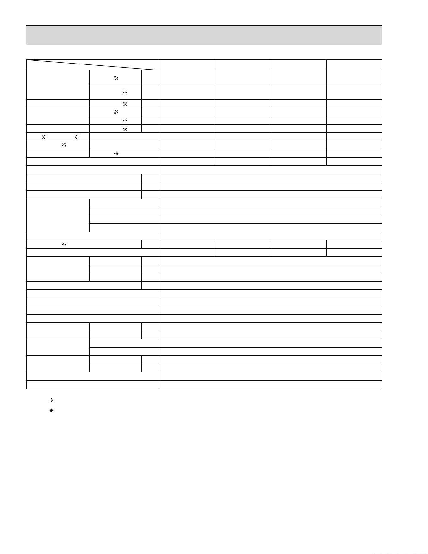
Item Model MSZ-A15NA MSY-A15NA MSZ-A17NA MSY-A17NA
Capacity
Rated
(Minimum-Maximum)
Cooling 1 Btu/h
15,000
(3,100-15,000)
15,000
(3,100-15,000)
16,200
(3,100-16,200)
16,200
(3,100-16,200)
Heating 47 1 Btu/h
18,000
(3,400-20,900)
–
20,100
(3,400-20,900)
–
Capacity Heating 17
2 Btu/h 13,000 – 13,000 –
Power consumption
Rated (Minimum-Maximum)
Cooling 1 W 1,690 (210-1,690) 1,690 (210-1,690) 2,070 (210-2,070) 2,070 (210-2,070)
Heating 47
1 W 1,790 (250-2,330) – 2,150 (250-2,330) –
Power consumption Heating 17 2 W 1,740 – 1,740 –
EER 1 [SEER]
3 Cooling 8.9 [16.0] 8.9 [16.0] 7.8 [16.0] 7.8 [16.0]
HSPF IV(V) 4 Heating 8.2 (7.1) – 8.2 (7.1) –
COP Heating
1 2.95 – 2.74 –
Outdoor unit model MUZ-A15NA MUY-A15NA MUZ-A17NA MUY-A17NA
Power supply V , phase , Hz 208/230, 1, 60
Max. fuse size (time delay) A 15
Min. circuit ampacity A 14
Fan motor F.L.A 0.52
Compressor
Model SNB130FPDH
Winding resistance (at 68ÛF)
0.45
R.L.A 10.1
L.R.A 12
Refrigerant control Liner expansion valve
Sound level 1 dB(A) 50 50 52 52
Defrost method 51 — 53 —
Dimensions
W in. 31-1/2
D in. 11-1/4
H in. 21-5/8
Weight Ib. 88
External ¿ nish Munsell 3Y 7.8/1.1
Remote controller Wireless type
Control voltage (by built-in transformer) 12 - 24 VDC
Refrigerant piping Not supplied
Refrigerant pipe size
(Min. wall thickness)
Liquid in. 1/4 (0.0315)
Gas in. 1/2 (0.0315)
Connection method
Indoor Flared
Outdoor Flared
Between the indoor &
outdoor units
Height difference ft. 40
Piping length ft. 65
Refrigerant charge (R410A) 2 lb. 7 oz.
Refrigeration oil (Model) NEO22
NOTE: Test conditions are based on ARI 210/240.
1: Rating conditions (Cooling) — Indoor: 80ÛFDB, 67ÛFWB, Outdoor: 95ÛFDB, (75ÛFWB) Rated frequency
(Heating) — Indoor: 70ÛFDB, 60ÛFWB, Outdoor: 47ÛFDB, 43ÛFWB Rated frequency
2: (Heating) — Indoor: 70ÛFDB, 60ÛFWB, Outdoor: 17ÛFDB, 15ÛFWB Maximum frequency
9
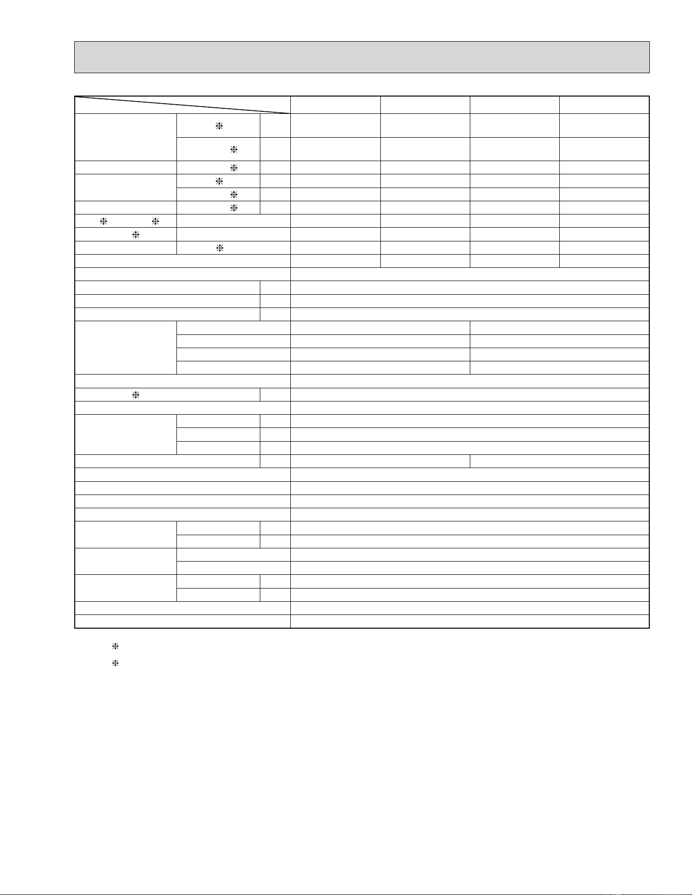
Item Model MSZ-A24NA MSY-A24NA MSZ-GA24NA MSY-GA24NA
Capacity
Rated Minimum-Maximum)
Cooling
1 Btu/h
22,000
(4,400-22,000)
22,000
(4,400-22,000)
22,000
(4,400-22,000)
22,000
(4,400-22,000)
Heating 47 1 Btu/h
23,200
(3,600-24,400)
—
23,200
(3,600-24,400)
—
Capacity Heating 17 2 Btu/h 15,200 — 15,200 —
Power consumption
Rated (Minimum-Maximum)
Cooling 1 W 2,880 (290-2,880) 2,880 (290-2,880) 2,500 (270-2,500) 2,500 (270-2,500)
Heating 47
1 W 2,350 (260-2,570) — 2,140 (250-2,520) —
Power consumption Heating 17
2 W 1,960 — 1,870 —
EER
1 [SEER] 3 Cooling 7.6 [16.0] 7.6 [16.0] 8.8 [17.5] 8.8 [17.5]
HSPF IV(V) 4 Heating 8.2 (7.1) — 9.5 (7.1) —
COP Heating
1 2.89 — 3.17 —
Outdoor unit model MUZ-A24NA MUY-A24NA MUZ-GA24NA MUY-GA24NA
Power supply V , phase , Hz 208/230, 1, 60
Max. fuse size (time delay) A 20
Min. circuit ampacity A 17
Fan motor F.L.A 0.93
Compressor
Model SNB130FPDH SNB130FQBH
Winding resistance (at 68ÛF)
0.45 0.98
R.L.A 10.1 12.8
L.R.A 16.0 16.0
Refrigerant control Liner expansion valve
Sound level 1 dB(A) 55
Defrost method Reverse cycle
Dimensions
W in. 33-1/16
D in. 13
H in. 33-7/16
Weight Ib. 128 117
External ¿ nish Munsell 3Y 7.8 1.1
Remote controller Wireless type
Control voltage (by built-in transformer) 12 - 24 VDC
Refrigerant piping Not supplied
Refrigerant pipe size
(Min. wall thickness)
Liquid in. 1/4 (0.0315)
Gas in. 5/8 (0.0394)
Connection method
Indoor Flared
Outdoor Flared
Between the indoor &
outdoor units
Height difference ft. 50
Piping length ft. 100
Refrigerant charge (R410A) 4 lb.
Refrigeration oil (Model) NEO22
NOTE: Test conditions are based on ARI 210/240.
1: Rating conditions (Cooling) — Indoor: 80ÛFDB, 67ÛFWB, Outdoor: 95ÛFDB, (75ÛFWB) Rated frequency
(Heating) — Indoor: 70ÛFDB, 60ÛFWB, Outdoor: 47ÛFDB, 43ÛFWB Rated frequency
2: (Heating) — Indoor: 70ÛFDB, 60ÛFWB, Outdoor: 17ÛFDB, 15ÛFWB Maximum frequency
10
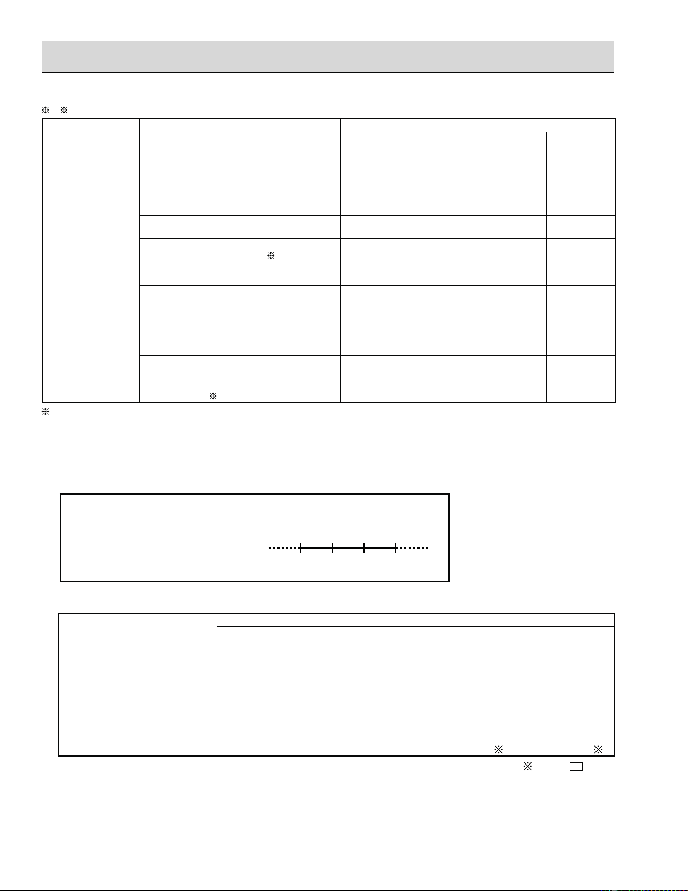
Test condition
3, 4
Mode Test
Indoor air condition (ÛF) Outdoor air condition (ÛF)
Dry bulb Wet bulb Dry bulb Wet bulb
ARI
SEER
(Cooling)
"A" Cooling Steady State at rated compres-
sor Speed
80 67 95 (75)
"B-2" Cooling Steady State at rated com-
pressor Speed
80 67 82 (65)
"B-1" Cooling Steady State at minimum
compressor Speed
80 67 82 (65)
Low ambient Cooling Steady State at mini-
mum compressor Speed
80 67 67 (53.5)
Intermediate Cooling Steady State At Inter-
mediate compressor Speed
5
80 67 87 (69)
HSPF
(Heating)
Standard Rating-Heating at rated compres-
sor Speed
70 60 47 43
Low temperature Heating at rated compres-
sor Speed
70 60 17 15
Max temperature Heating at minimum com-
pressor Speed
70 60 62 56.5
High temperature Heating at minimum com-
pressor Speed
70 60 47 43
Frost Accumulation at rated compressor
Speed
70 60 35 33
Frost Accumulation at Intermediate com-
pressor Speed 5
70 60 35 33
5: At Intermediate compressor Speed = ("Cooling rated compressor speed" - "minimum compressor speed") / 3 + "minimum
compressor speed".
OPERATING RANGE
(1) POWER SUPPLY
Rated voltage Guaranteed Voltage (V)
Outdoor unit
208/230 V
1 phase
60 Hz
Min.187
208 230 Max.253
(2) OPERATION
Mode Condition
Intake air temperature (°F)
Indoor Outdoor
DB WB DB WB
Cooling
Standard temperature 80 67 95 —
Maximum temperature 90 73 115 —
Minimum temperature 67 57 14 —
Maximum humidity 78% —
Heating
Standard temperature 70 60 47 43
Maximum temperature 80 67 75 65
Minimum temperature 70 60
14
5 (MUZ-GA24)
13
4 (MUZ-GA24)
Except -
U
model
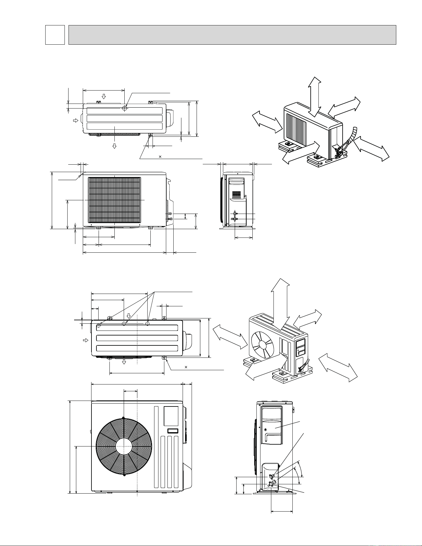
11
30°
35°
6-1/28
3-17/32
7-25/32
1-9/16
20-9/32
11-25/32
2-19/32
2
14-3/16
33-7/16
16-15/16
19-11/16
3-3/16
4-25/32
33-1/16
Open as a rule
20 inch or more if
the front and both
sides are open
4 inch or more /
8 inch or more if
there are obstacles
to both sides
Open as a rule
20 inch or more if the back,
both sides and top are open
14 in. or more
4 in. or more
Air in
Air out
13
Service panel
Gas refrigerant
pipe joint
Refrigerant pipe
(flared) ø5/8
Liquid refrigerant
pipe joint
Refrigerant pipe
(flared) ø1/4
Drain hole ø1-5/8
4-3/8 13/16 Oval hole
REQUIRED SPACE
Air in
Liquid pipe :1/4 (flared)
Gas pipe :3/8 (flared) ··· MUZ-A09/12NA
:1/2 (flared) ··· MUZ-A15/17NA, MUY-A15/17NA
6-23/32
2
5-7/8
2-23/32
1-3/4
15-3/4
12 ~ 12-3/4
13-9/16
11/16
1-9/16
7/8
21-5/8
11-1/32
13/32
31-1/2
19-11/16
5-15/16
11-29/32
17/3229/32 11-1/4
Air in
handle
Air in
Air out
2- 3/8 13/16 Oval hole
Drain hole ø1-5/8
{
REQUIRED SPACE
Basically open 4 inch or more
without any obstruction in front
and on both sides of the unit.
14 in. or more
8 in. or more
4 in. or more
4 in.
or more
Open two sides of left,
right, or rear side.
Unit: inch
MUZ-A09NA MUZ-A12NA MUZ-A15NA MUZ-A17NA MUY-A15NA MUY-A17NA
MUZ-A24NA MUY-A24NA MUZ-GA24NA MUY-GA24NA
4
OUTLINES AND DIMENSIONS
12
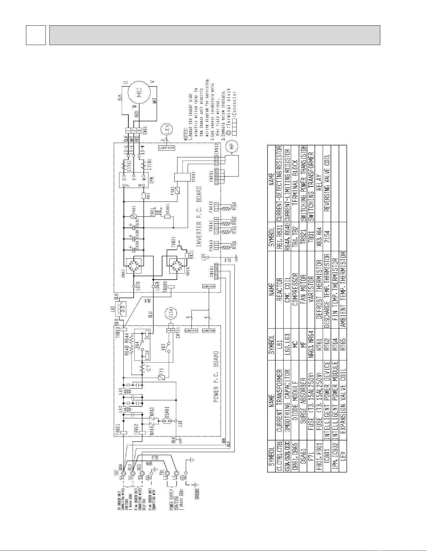
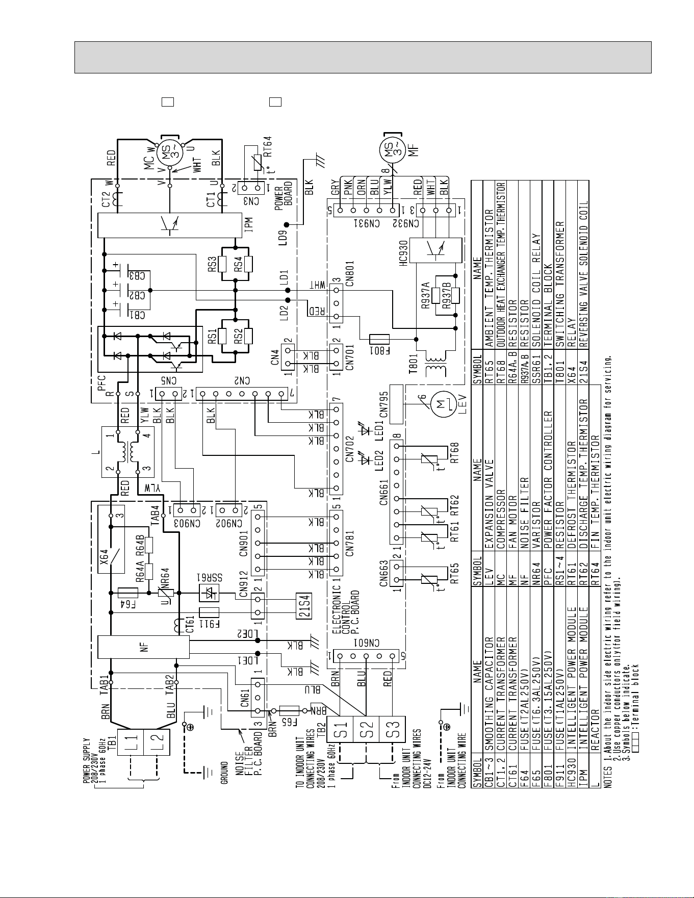
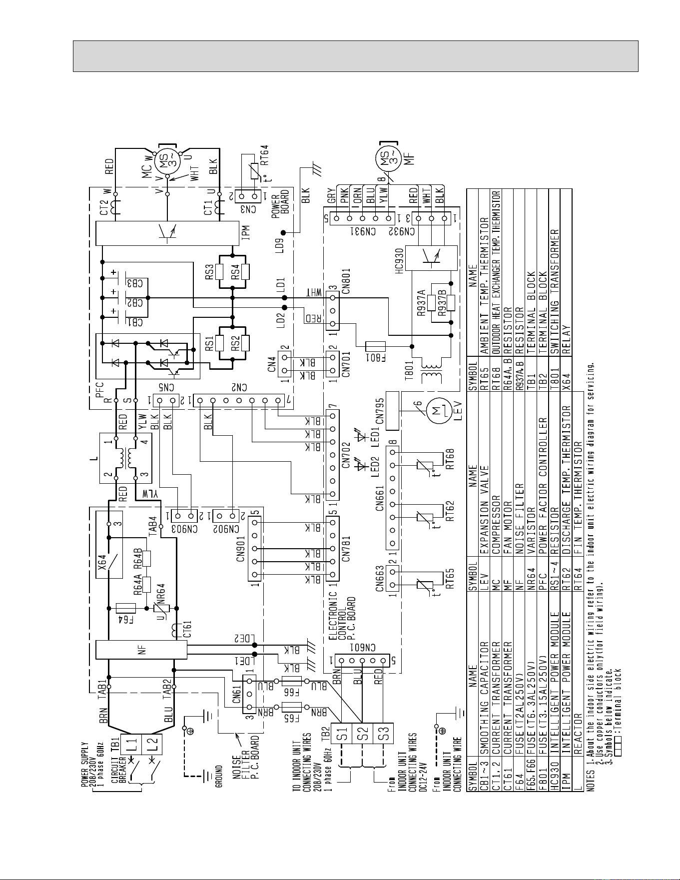
MUZ-A09NA MUZ-A12NA MUZ-A15NA MUZ-A17NA
5 WIRING DIAGRAM
13
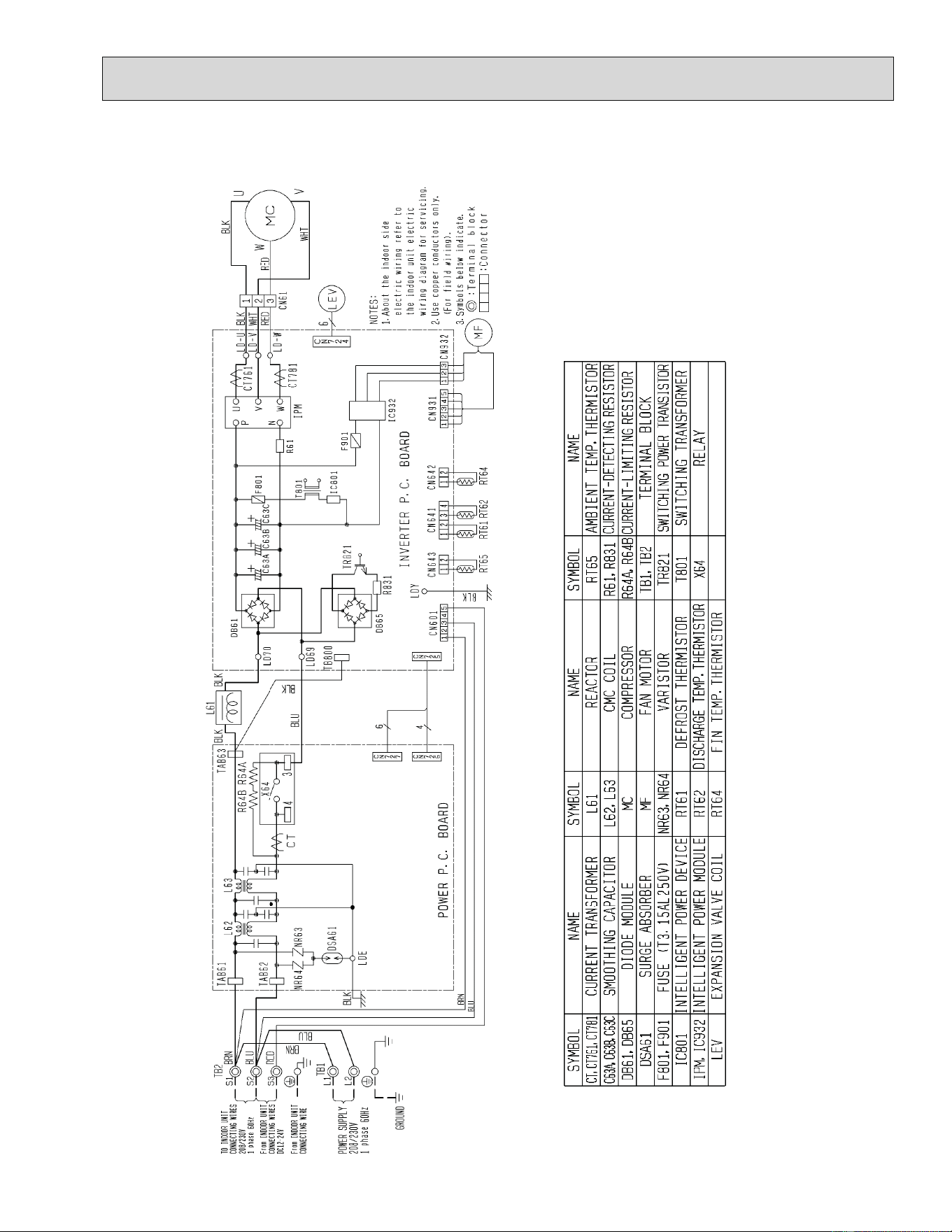
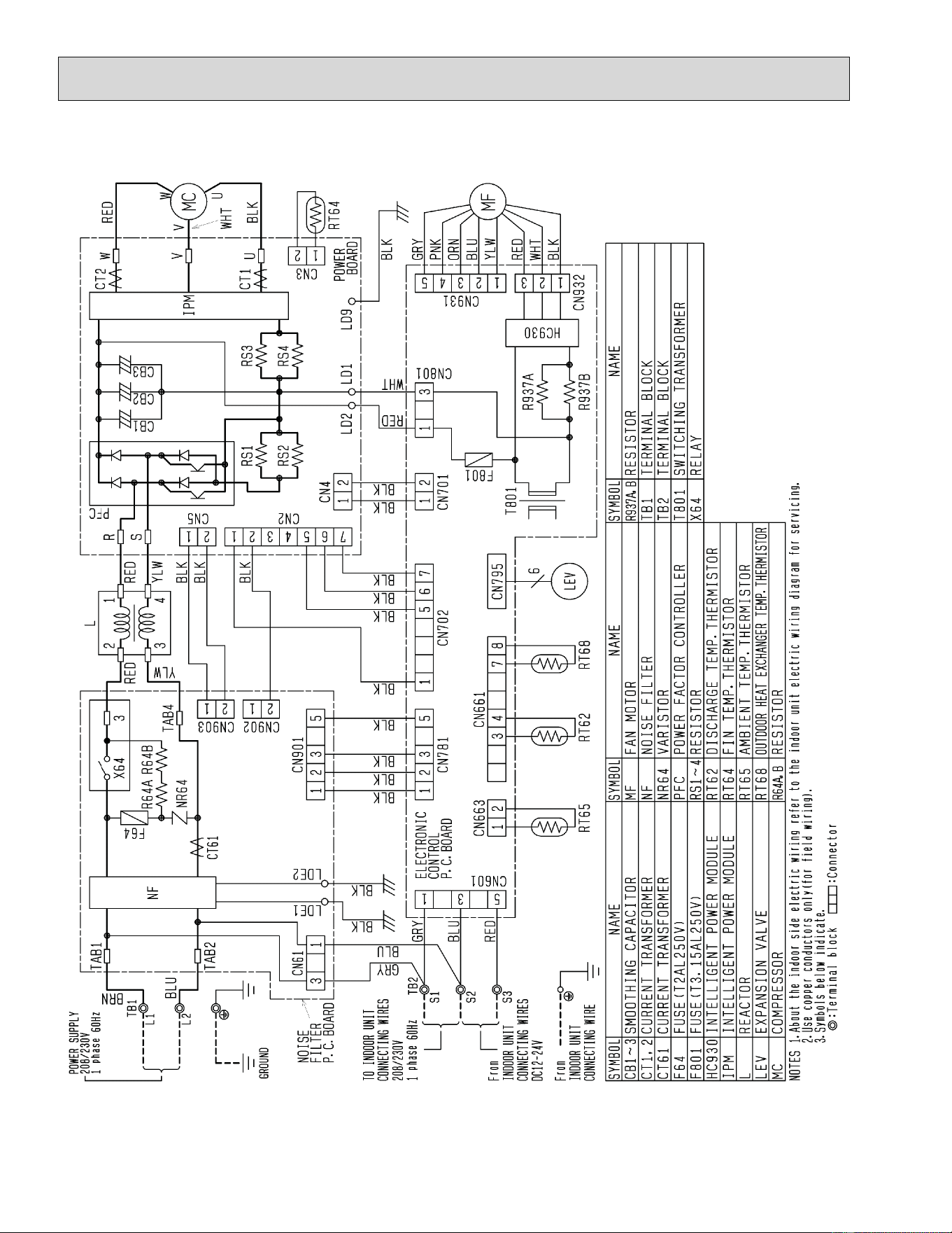
MUY-A15NA MUY-A17NA
14
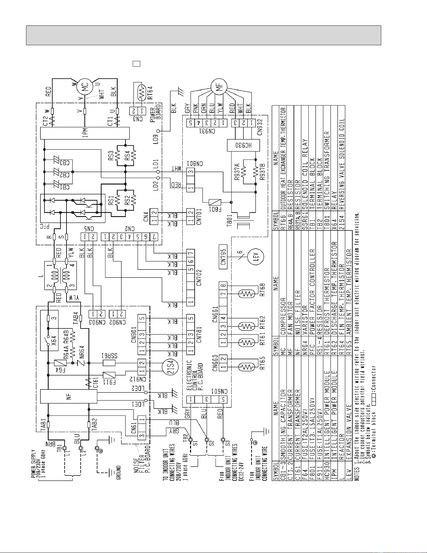
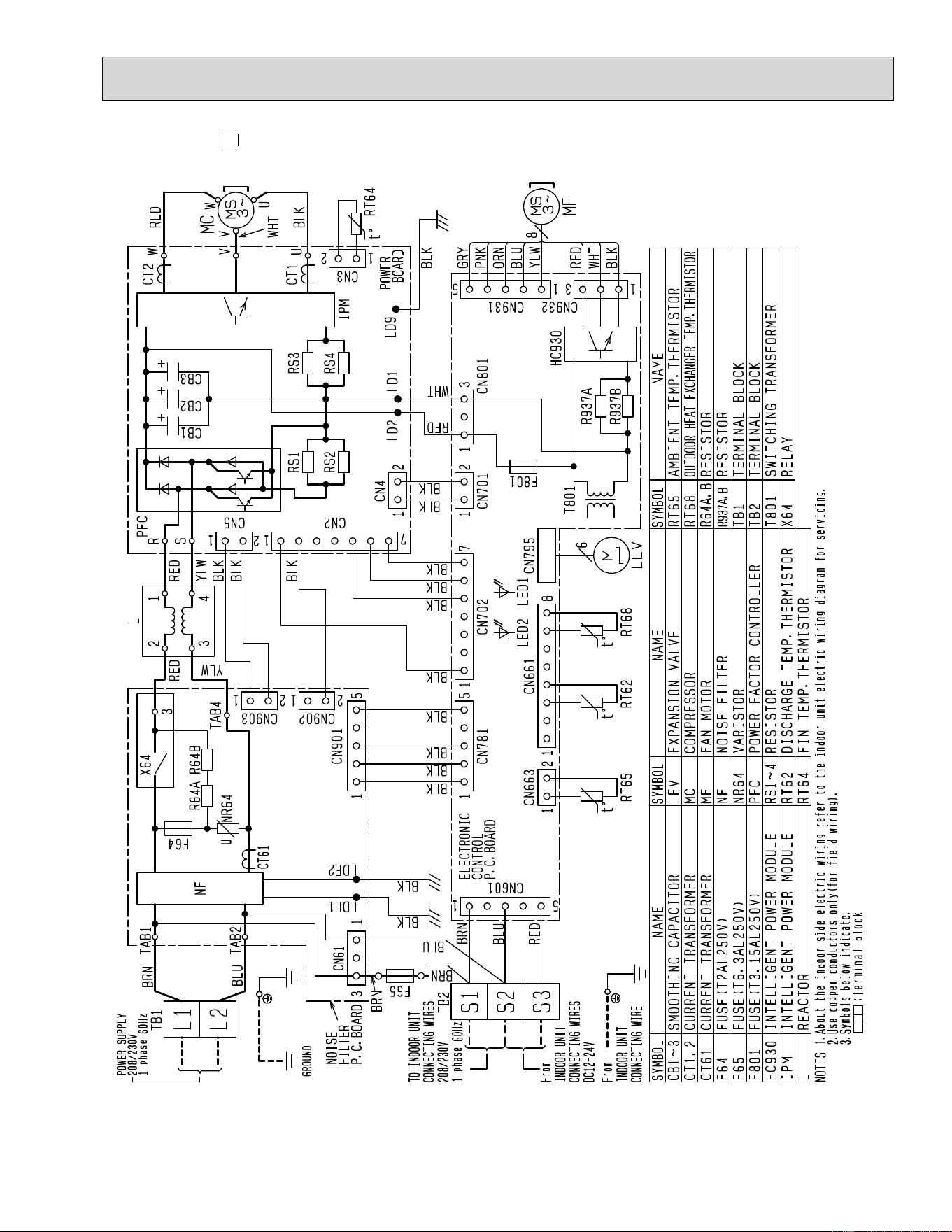
MUZ-A24NA MUZ-A24NA-
U1
15
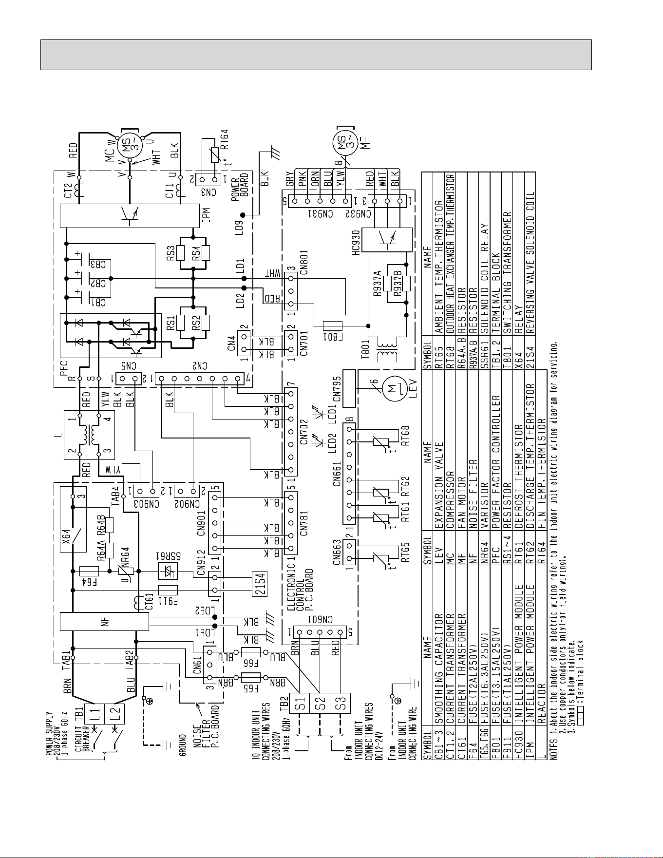
MUZ-A24NA-
1
MUZ-A24NA-
U2
16
MUY-A24NA
17
MUY-A24NA-
1
18
MUZ-GA24NA
19
MUY-GA24NA
20
Outdoor
heat
exchanger
Flared connection
Defrost
thermistor
RT61
Discharge
temperature
thermistor
RT62
Service
port
Service
port
Flared connection
Stop valve
(with strainer)
Stop valve
(with service port)
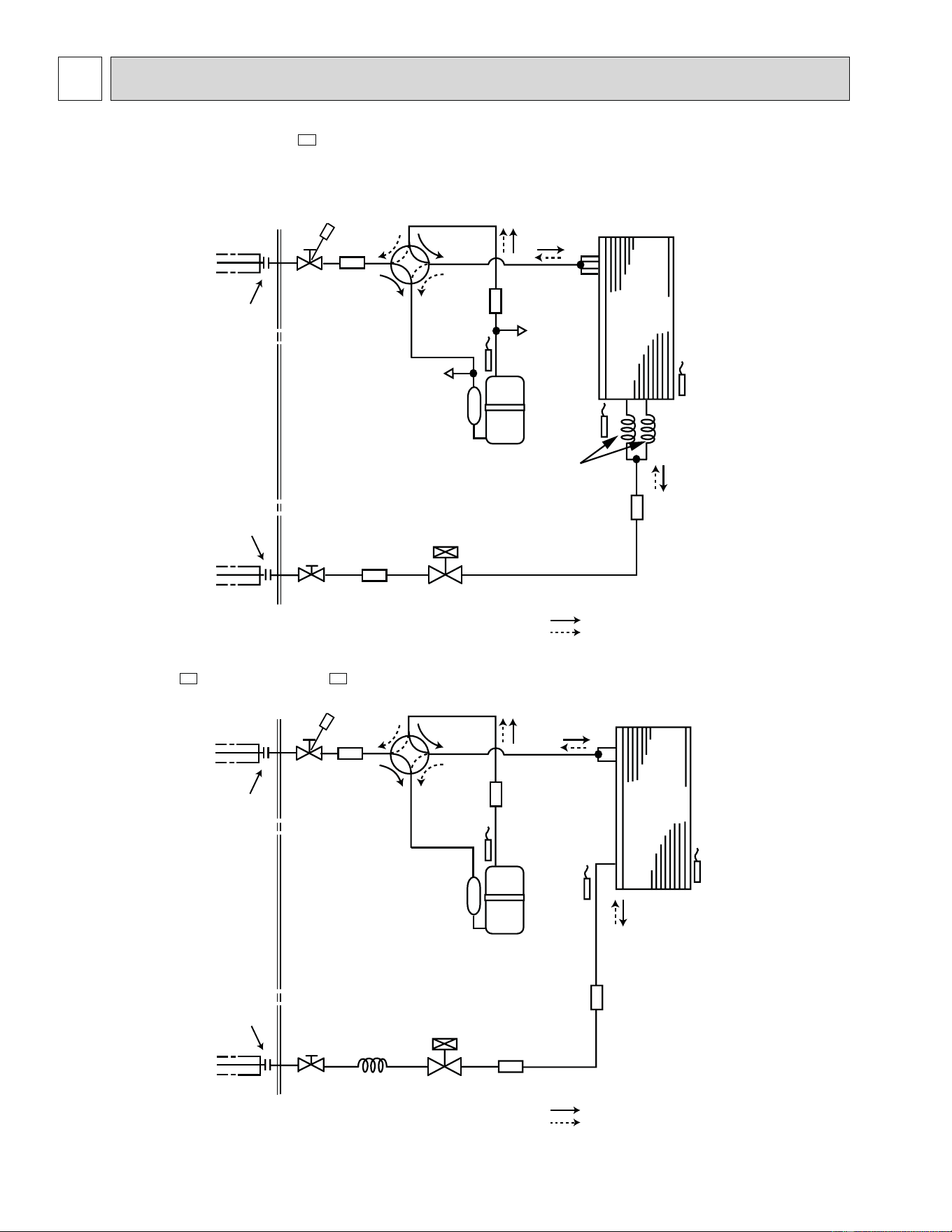
Refrigerant flow in cooling
Compressor
4-way valve
Refrigerant flow in heating (MUZ)
Refrigerant pipe ø3/8 (MUZ-A09/12)
ø1/2 (MUZ-A15/17,MUY-A15/17)
(with heat insulator)
Refrigerant pipe ø1/4
(with heat insulator)
R.V. coil
heating ON
cooling OFF
Strainer
#100
Capillary tube
O.D. 0.118 × I.D. 0.071
× 23-5/8
(ø
3.0
×
ø1.8
×
600
)
Expansion
valve
Ambient
temperature
thermistor
RT65
Muffler
Muffler
Muffler
Outdoor
heat
exchanger
Flared connection
Defrost
thermistor
RT61
Discharge
temperature
thermistor
RT62
Flared connection
Stop valve
(with strainer)
Stop valve
(with service port)
Refrigerant flow in cooling
Compressor
4-way valve
Refrigerant flow in heating
Refrigerant pipe ø3/8
(with heat insulator)
Refrigerant pipe ø1/4
(with heat insulator)
Capillary tube
O.D. 0.118 × I.D. 0.079
× 9-7/16
(ø3.0 × ø2.0 × 240)
Expansion
valve
R.V. coil
heating ON
cooling OFF
Strainer
#100
Muffler
Muffler
Ambient
temperature
thermistor
RT65
Muffler
Unit: inch
MUZ-A09NA MUZ-A09NA-
U1
MUZ-A12NA MUZ-A15NA MUZ-A17NA
MUY-A15NA MUY-A17NA
MUZ-A09NA-
1
MUZ-A09NA-
U2
6
REFRIGERANT SYSTEM DIAGRAM
21
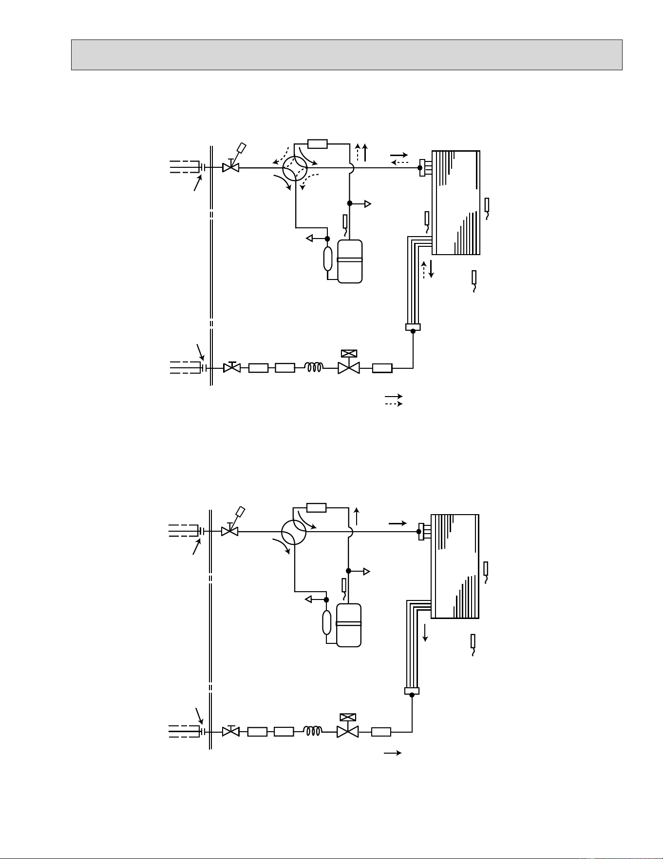
MUZ-A24NA MUZ-GA24NA
Outdoor
heat
exchanger
Flared connection
Defrost
thermistor
RT61
Service
port
Service
port
Discharge
temperature
thermistor
RT62
Flared connection
Stop valve
Stop valve
(with service port)
Capillary tube
Refrigerant flow in cooling
Compressor
4-way valve
Refrigerant flow in heating
Refrigerant pipe ø5/8
(with heat insulator)
Refrigerant pipe ø1/4
(with heat insulator)
LEV
R.V. coil
heating ON
cooling OFF
Muffler
#100
Strainer
#100
Receiver
Outdoor heat
exchanger
temperature
thermistor
RT68
Ambient
temperature
thermistor
RT65
Strainer
#100
O.D. 0.142 × I.D. 0.094
× 1-31/32
(ø
3.6 × ø2.4 × 50
)
MUY-A24NA MUY-GA24NA
Outdoor
heat
exchanger
Flared connection
Discharge
temperature
thermistor
RT62
Flared connection
Stop valve
Stop valve
(with service port)
Capillary tube
Refrigerant flow in cooling
Compressor
Service
port
Service
port
4-way valve
Refrigerant pipe ø5/8
(with heat insulator)
Refrigerant pipe ø1/4
(with heat insulator)
LEV
Muffler
#100
Strainer
#100
Receiver
Outdoor heat
exchanger
temperature
thermistor
RT68
Ambient
temperature
thermistor
RT65
Strainer
#100
O.D. 0.142 × I.D. 0.094
× 1-31/32
(ø
3.6 × ø2.4 × 50
)
Unit: inch
22
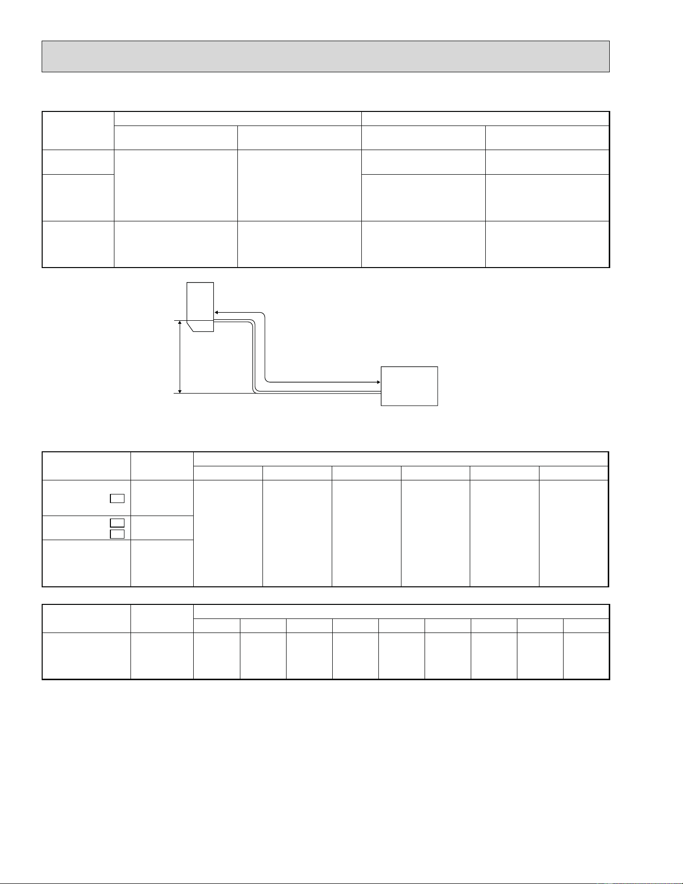
Max. Length
A
Max. Height
difference
B
Indoor
unit
Outdoor unit
MAX. REFRIGERANT PIPING LENGTH and MAX. HEIGHT DIFFERENCE
Model
Refrigerant piping: ft. Piping size O.D: in.
Max. Length
A
Max. Height difference
B
Gas Liquid
MUZ-A09NA
MUZ-A12NA
65 40
3/8 1/4
MUZ-A15NA
MUY-A15NA
MUZ-A17NA
MUY-A17NA
1/2 1/4
MUZ-A24NA
MUY-A24NA
MUZ-GA24NA
MUY-GA24NA
100 50 5/8 1/4
ADDITIONAL REFRIGERANT CHARGE (R410A: oz.)
Refrigerant piping exceeding 25 ft. requires additional refrigerant charge according to the calculation.
Model
Outdoor unit
precharged
Refrigerant piping length (one way): ft.
25 30 40 50 60 65
MUZ-A09NA
MUZ-A09NA -
U1
MUZ-A12NA
2 lb. 5 oz.
0 1.62 4.86 8.10 11.34 12.96
MUZ-A09NA -
1
MUZ-A09NA -
U2
2 lb.
MUZ-A15NA
MUY-A15NA
MUZ-A17NA
MUY-A17NA
2 lb. 7 oz.
Calculation: X oz. = 1.62/5 oz. / ft. × (Refrigerant piping length (ft.) - 25)
Model
Outdoor unit
precharged
Refrigerant piping length (one way): ft.
25 30 40 50 60 70 80 90 100
MUZ-A24NA
MUY-A24NA
MUZ-GA24NA
MUY-GA24NA
4 lb. 0 1.08 3.24 5.40 7.56 9.72 11.88 14.04 16.20
Calculation: X oz. = 1.08/5 oz. / ft. × (Refrigerant piping length (ft.) - 25)
NOTE: Refrigerant piping exceeding 25 ft. requires additional refrigerant charge according to the calculation.
23
MUZ-A09NA MUZ-A12NA MUZ-A15NA MUZ-A17NA MUZ-A24NA MUZ-GA24NA
MUY-A15NA MUY-A17NA MUY-A24NA MUY-GA24NA
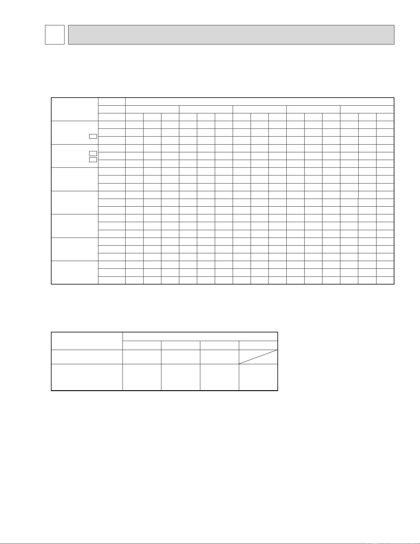
7-1. PERFORMANCE DATA
1) COOLING CAPACITY
Model
Indoor air Outdoor intake air DB temperature (ÛF)
IWB 75 85 95 105 115
(ÛF) TC SHC TPC TC SHC TPC TC SHC TPC TC SHC TPC TC SHC TPC
MUZ-A09NA
MUZ-A09NA
-
U1
71 11.0 6.4 0.61 10.3 5.9 0.67 9.7 5.6 0.72 9.0 5.2 0.76 8.3 4.8 0.79
67 10.4 7.4 0.58 9.7 6.9 0.64 9.0 6.4 0.69 8.4 5.9 0.73 7.7 5.5 0.77
63 9.8 8.3 0.55 9.1 7.7 0.61 8.5 7.1 0.66 7.7 6.5 0.70 7.0 5.9 0.73
MUZ-A09NA
-
1
MUZ-A09NA
-
U2
71 11.0 6.4 0.61 10.3 5.9 0.67 9.7 5.6 0.72 9.0 5.2 0.76 8.3 4.8 0.79
67 10.4 7.4 0.58 9.7 6.9 0.64 9.0 6.4 0.69 8.4 5.9 0.73 7.7 5.5 0.77
63 9.8 8.3 0.55 9.1 7.7 0.61 8.5 7.1 0.66 7.7 6.5 0.70 7.0 5.9 0.73
MUZ-A12NA
71 14.7 8.5 1.04 13.7 7.9 1.14 12.9 7.4 1.23 12.0 6.9 1.29 11.0 6.4 1.35
67 13.9 9.9 0.98 13.0 9.2 1.08 12.0 8.5 1.17 11.2 7.9 1.24 10.3 7.3 1.30
63 13.1 11.0 0.94 12.1 10.2 1.04 11.3 9.5 1.12 10.3 8.7 1.19 9.4 7.9 1.24
MUY-A15NA
MUZ-A15NA
71 18.4 9.5 1.50 17.2 8.9 1.65 16.1 8.3 1.77 15.0 7.8 1.87 13.8 7.1 1.94
67 17.4 11.3 1.42 16.2 10.5 1.56 15.0 9.8 1.69 14.0 9.1 1.79 12.8 8.3 1.88
63 16.4 12.8 1.35 15.2 11.9 1.50 14.1 11.0 1.61 12.8 10.0 1.72 11.7 9.2 1.79
MUY-A17NA
MUZ-A17NA
71 19.8 10.3 1.84 18.5 9.6 2.02 17.4 9.0 2.17 16.2 8.4 2.29 14.9 7.7 2.38
67 18.8 12.2 1.74 17.5 11.4 1.91 16.2 10.5 2.07 15.1 9.8 2.19 13.9 9.0 2.30
63 17.7 13.8 1.66 16.4 12.8 1.83 15.2 11.9 1.98 13.9 10.8 2.11 12.6 9.9 2.19
MUY-A24NA
MUZ-A24NA
71 27.0 13.4 2.56 25.2 12.5 2.81 23.7 11.7 3.02 22.0 10.9 3.18 20.2 10.1 3.31
67 25.5 16.1 2.42 23.8 15.0 2.66 22.0 13.9 2.88 20.5 12.9 3.05 18.8 11.9 3.20
63 24.0 18.3 2.30 22.2 17.0 2.55 20.7 15.8 2.75 18.8 14.4 2.94 17.2 13.1 3.05
MUY-GA24NA
MUZ-GA24NA
71 27.0 13.4 2.23 25.2 12.5 2.44 23.7 11.7 2.63 22.0 10.9 2.76 20.2 10.1 2.88
67 25.5 16.1 2.10 23.8 15.0 2.31 22.0 13.9 2.50 20.5 12.9 2.65 18.8 11.9 2.78
63 24.0 18.3 2.00 22.2 17.0 2.21 20.7 15.8 2.39 18.8 14.4 2.55 17.2 13.1 2.65
NOTE: 1. IWB: Intake air wet-bulb temperature
TC: Total Capacity (×10
3
Btu/h)
SHC: Sensible Heat Capacity (×10
3
Btu/h)
TPC: Total Power Consumption (kW)
2. SHC is based on 80ÛF of indoor Intake air DB temperature.
2) COOLING CAPACITY CORRECTIONS
Model
Refrigerant piping length (one way: ft.)
25 (std.) 40 65 100
MSZ-A09/12/15/17NA
MSY-A15/17NA
1.0 0.954 0.878
MSZ-A24NA
MSY-A24NA
MSZ-GA24NA
MSY-GA24NA
1.0 0.95 0.878 0.713
7 DATA
24
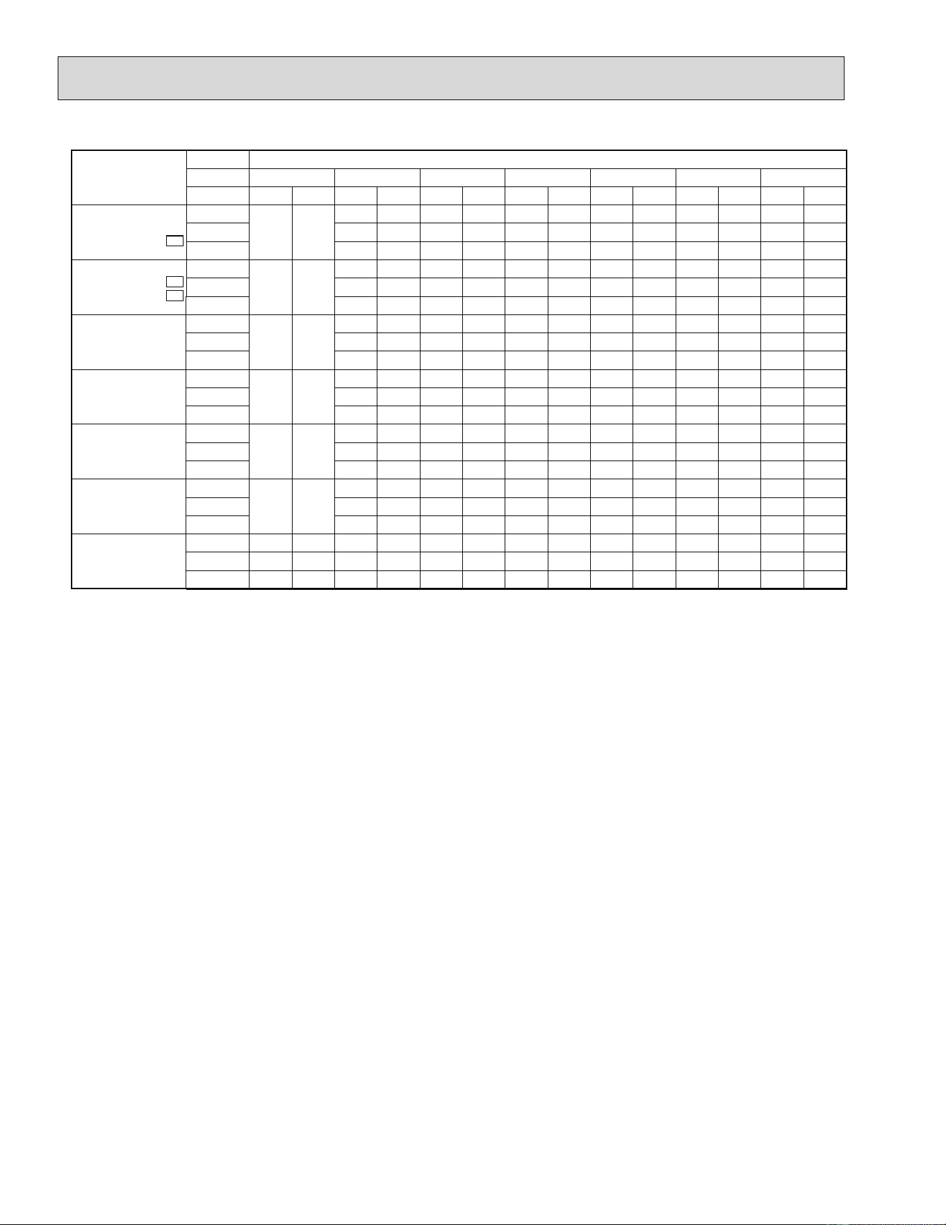
3) HEATING CAPACITY
Model
Indoor air Outdoor intake air WB temperature (ÛF)
IDB 5 15 25 35 43 45 55
(ÛF) TC TPC TC TPC TC TPC TC TPC TC TPC TC TPC TC TPC
MUZ-A09NA
MUZ-A09NA -
U1
75
——
6.3 0.64 7.9 0.75 9.4 0.84 10.6 0.88 11.0 0.89 12.4 0.93
70 6.7 0.62 8.2 0.74 9.6 0.82 10.9 0.86 11.2 0.88 12.7 0.91
65 6.9 0.59 8.6 0.71 10.0 0.80 11.2 0.84 11.6 0.85 13.0 0.89
MUZ-A09NA -
1
MUZ-A09NA -
U2
75
——
6.3 0.64 7.9 0.75 9.4 0.84 10.6 0.88 11.0 0.89 12.4 0.93
70 6.7 0.62 8.2 0.74 9.6 0.82 10.9 0.86 11.2 0.88 12.7 0.91
65 6.9 0.59 8.6 0.71 10.0 0.80 11.2 0.84 11.6 0.85 13.0 0.89
MUZ-A12NA
75
——
7.9 0.86 9.9 1.02 11.8 1.13 13.3 1.19 13.7 1.21 15.5 1.25
70 8.4 0.84 10.2 0.99 12.0 1.10 13.6 1.16 14.0 1.18 15.8 1.23
65 8.6 0.80 10.7 0.96 12.4 1.07 14.0 1.13 14.4 1.15 16.2 1.21
MUZ-A15NA
75
——
10.4 1.33 13.1 1.57 15.6 1.75 17.6 1.83 18.1 1.86 20.5 1.93
70 11.1 1.29 13.5 1.53 15.9 1.70 18.0 1.79 18.5 1.83 21.0 1.90
65 11.3 1.24 14.1 1.48 16.5 1.66 18.5 1.75 19.1 1.77 21.4 1.86
MUZ-A17NA
75
——
11.7 1.60 14.6 1.88 17.4 2.10 19.6 2.20 20.2 2.24 22.9 2.32
70 12.4 1.55 15.1 1.84 17.8 2.04 20.1 2.15 20.7 2.19 23.4 2.28
65 12.7 1.48 15.8 1.77 18.4 1.99 20.7 2.10 21.3 2.13 23.9 2.24
MUZ-A24NA
75
——
13.5 1.75 16.8 2.06 20.1 2.29 22.6 2.41 23.3 2.44 26.4 2.54
70 14.3 1.69 17.4 2.01 20.5 2.23 23.2 2.35 23.9 2.40 27.0 2.49
65 14.6 1.62 18.2 1.94 21.2 2.17 23.9 2.29 24.6 2.33 27.6 2.44
MUZ-GA24NA
75 10.2 1.26 13.5 1.59 16.8 1.87 20.1 2.09 22.6 2.19 23.3 2.23 26.4 2.31
70 11.0 1.21 14.3 1.54 17.4 1.83 20.5 2.03 23.2 2.14 23.9 2.18 27.0 2.27
65 11.6 1.16 14.6 1.48 18.2 1.77 21.2 1.98 23.9 2.09 24.6 2.12 27.6 2.23
NOTE: 1. IDB: Intake air dry-bulb temperature
TC: Total Capacity (×10
3
Btu/h)
TPC: Total Power Consumption (kW)
2. Above data is for heating operation without any frost.
How to operate with fixed operational frequency of the compressor.
1. Press the EMERGENCY OPERATION switch on the front of the indoor unit, and select either EMERGENCY COOL
mode or EMERGENCY HEAT mode before starting to operate the air conditioner.
2. The compressor starts with operational frequency.
3. The fan speed of the indoor unit is High.
4. This operation continues for 30 minutes.
5. In order to release this operation, press the EMERGENCY OPERATION switch twice or once, or press any button on
the remote controller.
25
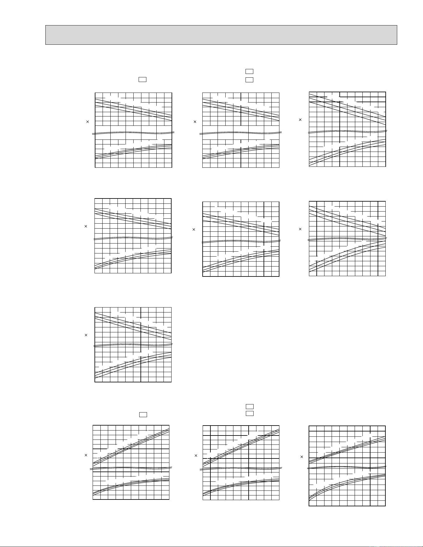
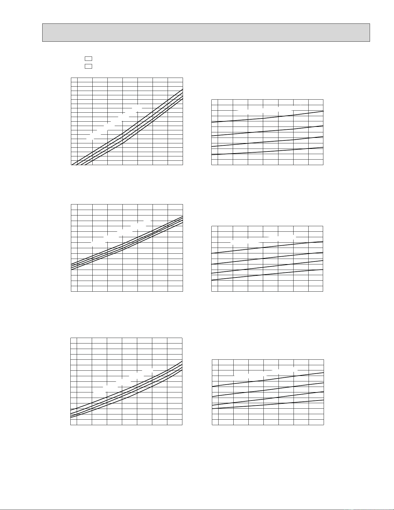
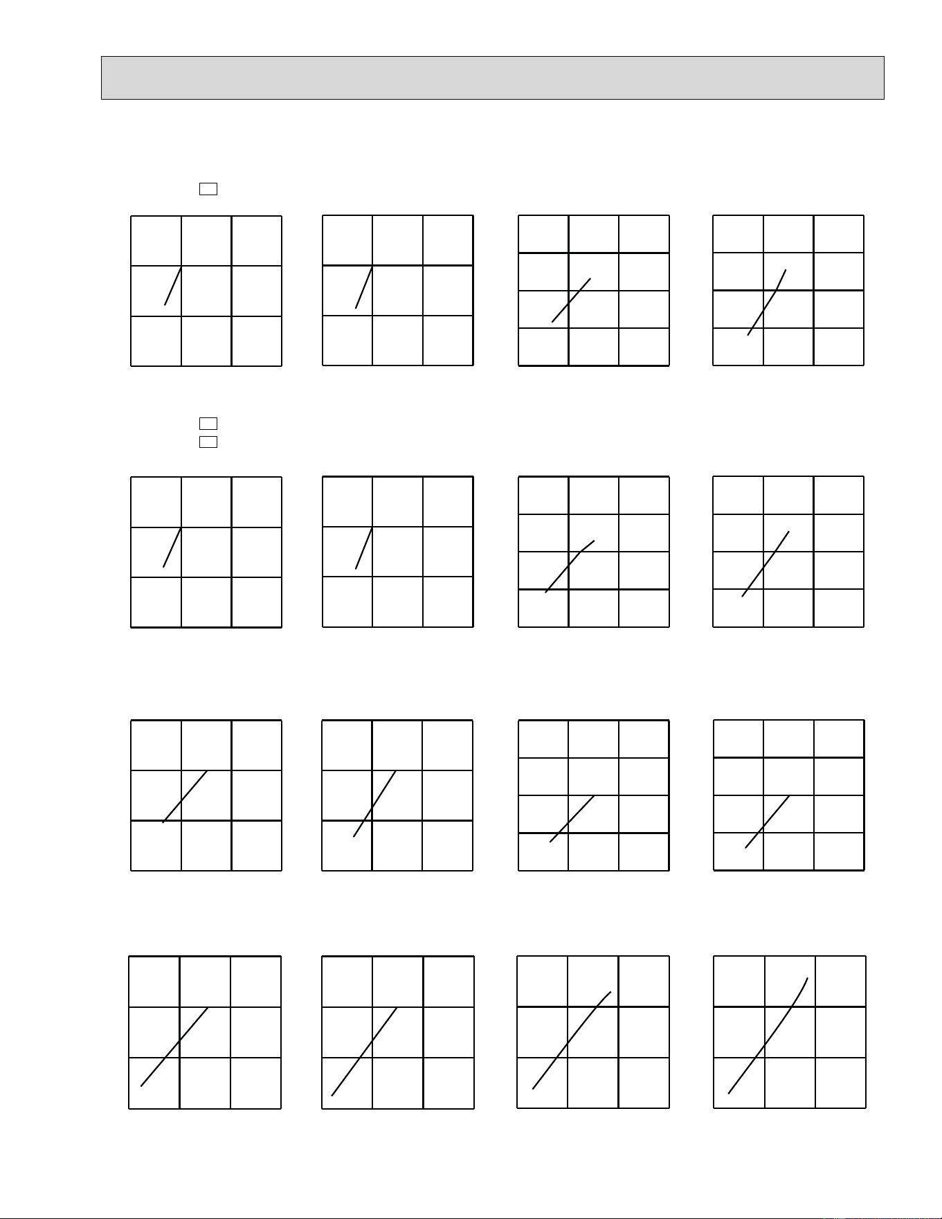
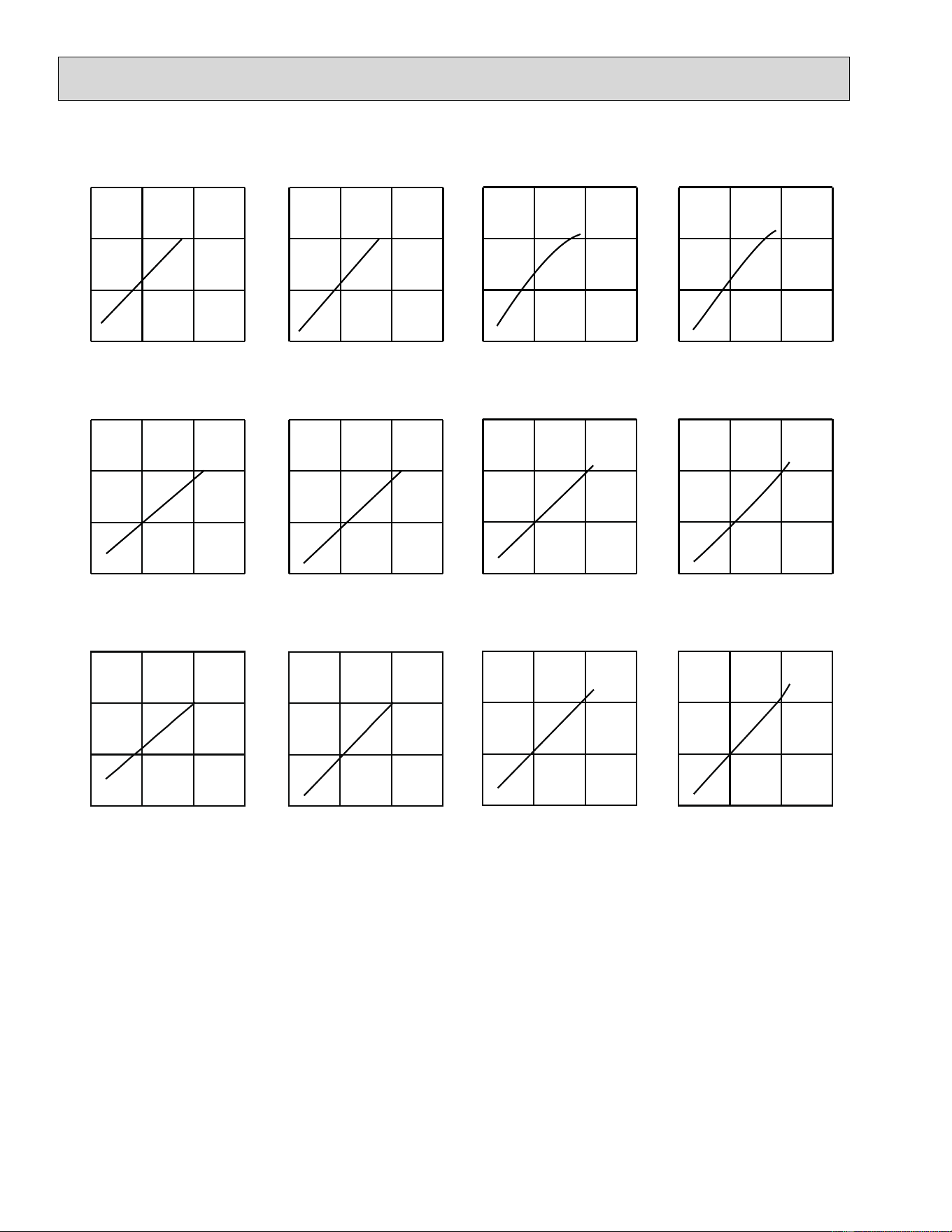
7-2. PERFORMANCE CURVE
65
70
75
75
70
65
Total power consumption
(kW)
Total capacity
(10
3
Btu/h)
Outdoor intake air WB temperature (°F)
= 307 CFM
Airflow
12
14
10
8
9
11
13
15
7
1.0
15 25 35 45 55
0.8
0.6
0.7
0.9
Ind
oor intake air DB temperature (°F)
Indoor intak
e air DB temperature (°F)
65
70
75
75
70
65
20
12
8
16
22
18
10
14
Indoor intake air DB temperature (°F)
= 318 CFM
Airflow
15 25 35 45 55
Outdoor intake air WB temperature (°F)
1.3
0.8
0.9
1.0
1.1
1.2
Indoor intak
e air
DB temperat
ure (°F)
Total power consumption
(kW)
Total capacity
(10
3
Btu/h)
Cooling
71
67
63
71
67
63
Outdoor intake air DB temperature (°F)
SHF at rating condition = 0.71
= 275 CFM
Airflow
6
8
7
9
10
11
12
0.9
65 75 85 95 105 115
0.7
0.6
0.8
Indoor intak
e air WB temperat
ure (°F)
Indoor intake air WB temperature (°F)
0.5
0.4
Total power consumption
(kW)
Total capacity
(10
3
Btu/h)
71
67
63
71
67
63
24
22
20
18
12
16
14
2.5
2.3
2.1
1.9
1.7
1.5
Ind
oor intake air WB temperature (°F)
Indoor intake air WB temperature (°F)
SHF at rating condition = 0.65
= 342 CFM
Airflow
65 75 85 95 105 115
Outdoor intake air DB temperature (°F)
Total power consumption
(kW)
Total capacity
(10
3
Btu/h)
71
63
67
71
63
67
27
29
23
19
25
21
17
3.1
2.9
2.7
2.5
2.3
2.1
Indoor intake air WB temperature (°F)
Indoor intake air
WB temperature (°F)
SHF at rating condition = 0.63
= 508 CFM
Airflow
65 75 85 95 105 115
Outdoor intake air DB temperature (°F)
Total power consumption
(kW)
Total capacity
(10
3
Btu/h)
71
67
63
71
67
63
15
13
9
11
1.4
1.3
1.2
1.1
1.0
0.9
Indoor intake air WB temperature (°F)
Indoor intake air WB temperature (°F)
SHF at rating condition = 0.70
= 318 CFM
Airflow
65 75 85 95 105 115
Outdoor intake air DB temperature (°F)
Total power consumption
(kW)
Total capacity
(10
3
Btu/h)
71
67
63
71
67
63
22
18
10
14
2.2
2.0
1.8
1.6
1.4
1.2
Indoor intake air WB temperature (°F)
Ind
oor intake air WB temperature (°F)
SHF at rating condition = 0.65
= 342 CFM
Airflow
65 75 85 95 105 115
Outdoor intake air DB temperature (°F)
Total power consumption
(kW)
Total capacity
(10
3
Btu/h)
MUZ-A09NA
MUZ-A09NA
-
U1
MUZ-A09NA
MUZ-A09NA
-
U1
MUZ-A12NA
MUZ-A15NA MUY-A15NA
MUZ-A17NA MUY-A17NA
MUZ-A24NA MUY-A24NA
Heating
MUZ-A12NA
MUZ-A09NA
-
1
MUZ-A09NA-
U2
MUZ-A09NA-
1
MUZ-A09NA-
U2
71
67
63
71
67
63
Outdoor intake air DB temperature (°F)
SHF at rating condition = 0.71
= 275 CFM
Airflow
6
8
7
9
10
11
12
0.9
65 75 85 95 105 115
0.7
0.6
0.8
Indoor intak
e air WB temperature (°F)
Indoor intake air WB temperature (°F
)
0.5
0.4
Total power consumption
(kW)
Total capacity
(10
3
Btu/h)
65
70
75
75
70
65
Total power consumption
(kW)
Total capacity
(10
3
Btu/h)
Outdoor intake air WB temperature (°F)
= 307 CFM
Airflow
12
14
10
8
9
11
13
15
7
1.0
15 25 35 45 55
0.8
0.6
0.7
0.9
Indoor intake air DB temperat
ure
(°F)
Indoor intake air DB temperature (°F)
71
63
67
71
63
67
27
29
23
19
25
21
17
2.9
2.7
2.5
2.3
2.1
1.7
Indoor intake air WB temperature (°F)
Indoor intake air WB tempe
rat
ure (°F)
SHF at rating condition = 0.63
= 508 CFM
Airflow
65 75 85 95 105 115
Outdoor intake air DB temperature (°F)
Total power consumption
(kW)
Total capacity
(10
3
Btu/h)
MUZ-GA24NA MUY-GA24NA
26
65
70
75
75
70
65
Outdoor intake air WB temperature (°F)
Airflow= 381 CFM
18
22
24
14
10
1.8
1.9
1.7
15 25 35 45 55
1.5
1.3
1.4
1.6
Indoor intake air DB temperature (°F)
Indoor intake air DB temperature (°F)
Total power consumption
(kW)
Total capacity
(×10
3
Btu/h)
65
70
75
75
70
65
24
20
12
16
Indoor intake air DB temperature (°F)
= 381 CFM
Airflow
15 25 35 45 55
Outdoor intake air WB temperature (°F)
2.4
1.4
1.6
1.8
2.0
2.2
Indoor intake air DB temperature (°F)
Total power consumption
(kW)
Total capacity
(10
3
Btu/h)
65
70
75
75
70
65
28
26
24
22
16
14
20
18
2.6
1.6
Indoor intake air DB temperature (°F)
= 568 CFM
Airflow
15 25 35 45 55
Outdoor intake air WB temperature (°F)
1.8
2.0
2.2
2.4
Indoor intake air
DB temperature (°F)
Total power consumption
(kW)
Total capacity
(10
3
Btu/h)
MUZ-A15NA
MUZ-A17NA
MUZ-A24NA
10
12
14
16
18
20
22
24
26
28
30
32
65
70
75
75
70
65
= 568 CFM
Airflow
15525354555
Outdoor intake air WB temperature (°F)
Indoor intake air DB temperature (°F)
Total power consumption
(kW)
Total capacity
(10
3
Btu/h)
1.0
1.2
1.4
1.6
1.8
2.0
2.2
2.4
Indoor intake air DB tem
perature
(°F)
MUZ-GA24NA
This value of frequency is not the same as the actual frequency in operating. Refer to 7-5 and 7-6 for the relationships
between frequency and capacity.
Data is based on the condition of indoor humidity 50%.
Air flow should be set to High speed.
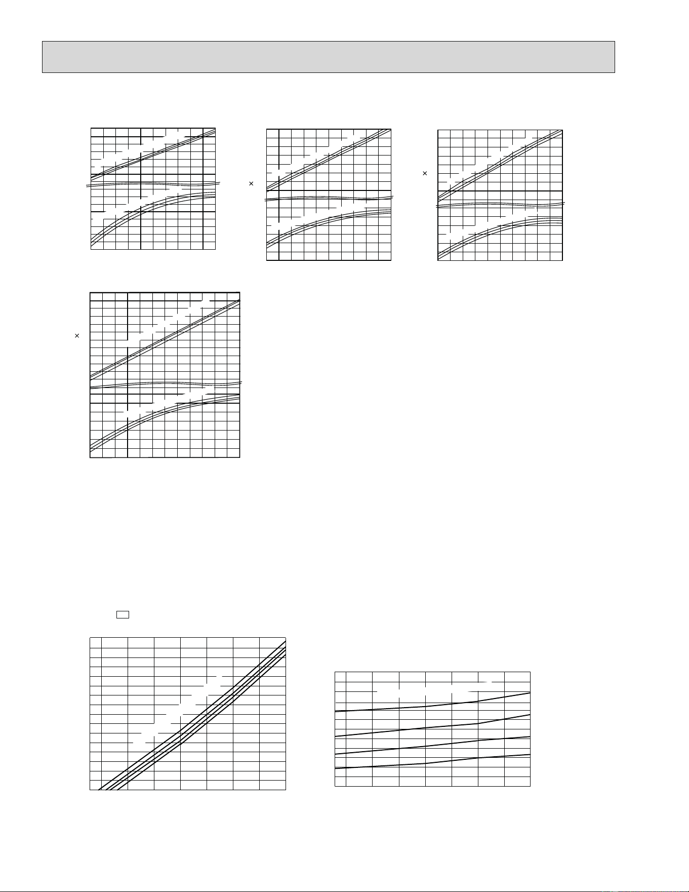
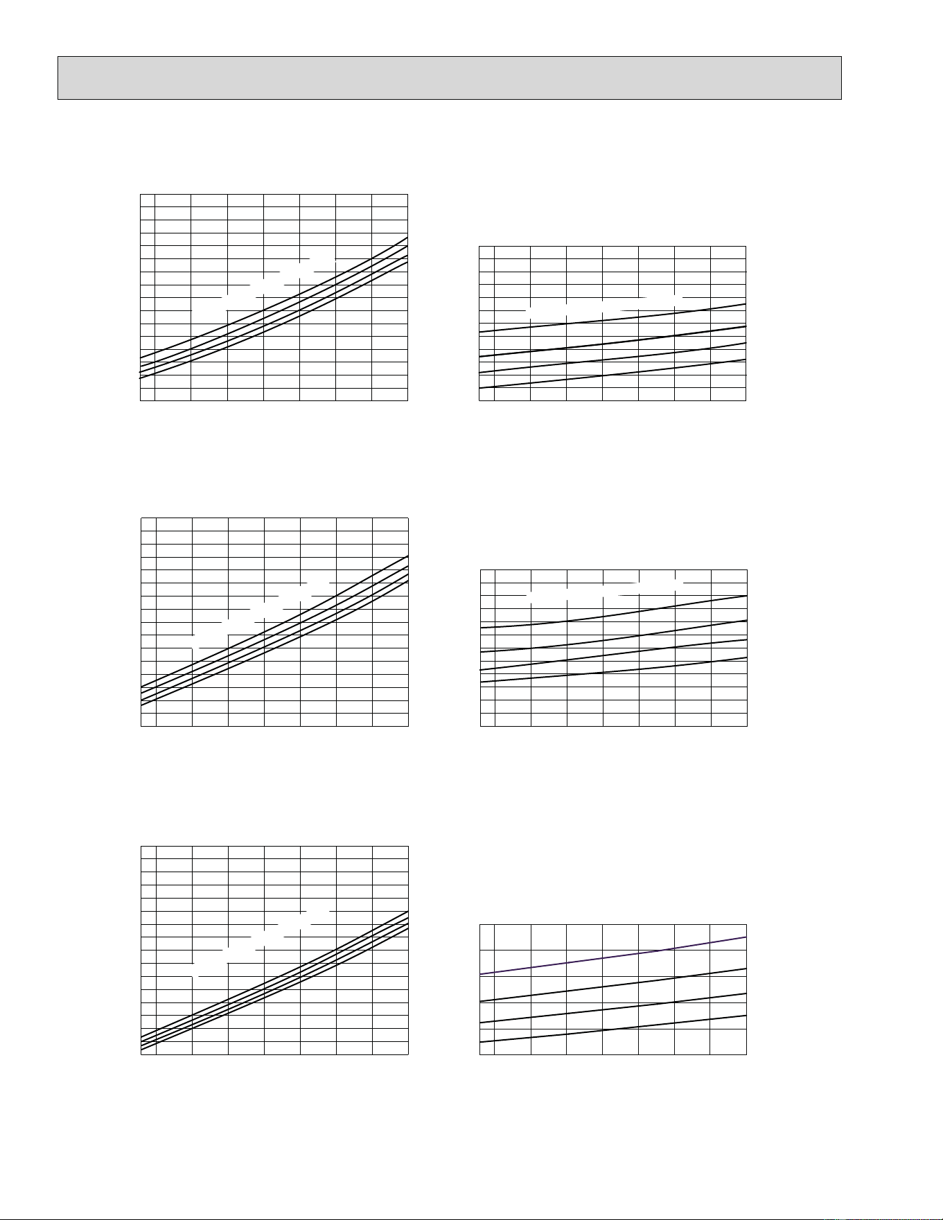
7-3. Condensing pressure
Cooling
68 70 75 80 85 90 95 100 105
(°F)
110
115
120
125
130
135
140
145
150
155
160
165
170
(PSIG)
Condensing pressure
86
80
75
70
Suction pressure
Outdoor ambient temperature
Indoor DB temperature (°F)
(PSIG)
86
80
75
70
68 70 75 80 85 90 95 100 105
(°F)
260
280
300
320
340
360
380
400
420
Indoor DB temperature (°F)
Outdoor ambient temperature
MUZ-A09NA
MUZ-A09NA
-
U1
27
68 70 75 80 85 90 95 100 105
(°F)
90
95
100
105
110
115
120
125
130
135
140
145
150
(PSIG)
Condensing pressure
86
80
75
70
Suction pressure
Outdoor ambient temperature
Indoor DB temperature (°F)
(PSIG)
86
80
75
70
68 70 75 80 85 90 95 100 105
(°F)
180
220
260
300
340
380
420
460
500
Indoor DB temperature (°F)
Outdoor ambient temperature
MUZ-A12NA
MUZ-A09NA
-
1
MUZ-A09NA-
U2
(PSIG)
Condensing pressure
86
80
75
70
68 70 75 80 85 90 95 100 105
(°F)
280
300
340
360
380
400
420
460
480
Indoor DB temperature (°F)
Outdoor ambient temperature
320
68 70 75 80 85 90 95 100 105
(°F)
110
115
120
125
130
135
140
145
150
155
160
165
170
Suction pressure
Outdoor ambient temperature
Indoor DB temperature (°F)
(PSIG)
86
80
75
70
440
MUZ-A15NA
MUY-A15NA
68 70 75 80 85 90 95 100 105(°F)
80
85
90
95
100
105
110
115
120
125
130
135
140
(PSIG)
Condensing pressure
86
80
75
70
Suction pressure
Outdoor ambient temperature
Indoor DB
temperature (°F
)
(PSIG)
86
80
75
70
68 70 75 80 85 90 95 100 105(°F)
260
300
340
380
420
460
500
540
580
Ind
oor DB
temperature (°F)
Outdoor ambient temperature
28
MUZ-A24NA
MUY-A24NA
68 70 75 80 85 90 95 100 105(°F)
70
75
80
85
90
95
100
105
110
115
120
125
130
(PSIG)
Condensing pressure
86
80
75
70
Suction pressure
Outdoor ambient temperature
Indoor DB temperat
ure (°F)
(PSIG)
86
80
75
70
68 70 75 80 85 90 95 100 105(°F)
260
300
340
380
420
460
500
540
580
Indoor DB temperature (°F)
Outdoor ambient temperature
MUZ-A17NA
MUY-A17NA
(PSIG)
Condensing pressure
86
80
75
70
68 70 75 80 85 90 95 100 105(°F)
80
85
90
95
100
105
110
115
120
125
130
135
140
Suction pressure
Outdoor ambient temperature
Indoor DB temperature (°F)
(PSIG)
86
80
75
70
68 70 75 80 85 90 95 100 105(°F)
260
300
340
380
420
460
500
540
580
Indoor DB temperature (°F)
Outdoor ambient temperature
MUZ-GA24NA
MUY-GA24NA
(PSIG)
Condensing pressure
86
80
75
70
86
80
75
70
68 70 75 80 85 90 95 100 105(°F)
260
300
340
380
420
460
500
540
580
Indoor DB temperature (°F)
Outdoor ambient temperature
Suction pressure
68 70 75 80 85 90 95 100 105(°F)
Outdoor ambient temperature
(PSIG)
100
110
120
130
140
150
29
Data is based on the condition of outdoor humidity 75%.
Air flow should be set to High speed.
Data is for heating operation without any frost.
Heating
MUZ-A12NA
75
70
65
(PSIG) (PSIG)
Condensing pressure
Outdoor ambient temperature
14 20 25 30 35 40 45 50 55 60 65 70(°F)
340
320
300
280
260
240
360
380
400
440
420
460
480
Indoor DB temperature(°F)
75
70
65
Suction pressure
Outdoor ambient temperature
14 20 25 30 35 40 45 50 55
58Hz
58Hz
60 65 70(°F)
70
60
80
90
100
110
120
130
140
150
160
170
Indoor DB temperature (°F)
75
70
65
(PSIG) (PSIG)
Condensing pressure
Outdoor ambient temperature
14 20 25 30 35 40 45 50 55 60 65 70(°F)
340
320
300
280
260
240
360
380
400
440
420
460
480
Indoor DB temperature(°F)
75
70
65
Suction pressure
Outdoor ambient temperature
14 20 25 30 35 40 45 50 55
58Hz
58Hz
60 65 70(°F)
70
60
80
90
100
110
120
130
140
150
160
170
Indoor DB temperature (°F)
MUZ-A09NA
MUZ-A09NA
-
U1
MUZ-A09NA-
1
MUZ-A09NA-
U2
75
70
60
(PSIG) (PSIG)
Condensing pressure
Outdoor ambient temperature
14 20 25 30 35 40 45 50 55 60 65 70(°F)
340
320
300
280
260
240
360
380
400
440
420
460
480
Indoor DB temperature(°F)
75
70
65
Suction pressure
Outdoor ambient temperature
14 20 25 30 35 40 45 50 55
58Hz
58Hz
60 65 70(°F)
70
60
80
90
100
110
120
130
140
150
160
170
Indoor DB temperature (°F)
30
MUZ-A24NA
MUZ-A17NA
75
70
65
(PSIG) (PSIG)
Condensing pressure
Outdoor ambient temperature
14 20 25 30 35 40 45 50 55 60 65 70(°F)
260
220
180
140
100
300
340
380
460
420
500
540
580
620
Indoor DB temperature(°F)
75
70
65
Suction pressure
Outdoor ambient temperature
14 20 25 30 35 40 45 50 55
58Hz
58Hz
60 65 70(°F)
70
60
50
80
90
100
110
120
130
140
150
160
Indoor DB temperature (°F)
75
70
65
(PSIG) (PSIG)
Condensing pressure
Outdoor ambient temperature
14 20 25 30 35 40 45 50 55 60 65 70(°F)
280
260
240
220
200
300
320
340
380
360
400
420
440
460
Indoor DB temperature(°F)
75
70
65
Suction pressure
Outdoor ambient temperature
14 20 25 30 35 40 45 50 55
58Hz
60 65 70(°F)
70
60
50
80
90
100
110
120
130
140
150
160
Indoor DB temperature (°F)
58Hz
MUZ-A15NA
75
70
65
(PSIG) (PSIG)
Condensing pressure
Outdoor ambient temperature
14 20 25 30 35 40 45 50 55 60 65 70(°F)
260
220
180
140
100
300
340
380
460
420
500
540
580
620
Indoor
DB temperature(°F)
75
70
65
Suction pressure
Outdoor ambient temperature
14 20 25 30 35 40 45 50 55
58Hz
58Hz
60 65 70(°F)
70
60
50
80
90
100
110
120
130
140
150
160
Ind
oor
DB temperature (°F)
31
MUZ-GA24NA
(PSIG)
Condensing pressure
Suction pressure
200
220
240
260
280
300
320
340
360
380
75
70
65
(PSIG)
Outdoor ambient temperature
1552010 25 30 35 40 45 50 55 60 65 70(°F)
58Hz
Ind
oor
DB temperature(
°F)
40
50
60
70
80
90
100
110
120
130
140
150
160
170
75
70
65
58Hz
Indoor DB temperature (°F)
Outdoor ambient temperature
15 20105 25303540455055606570(°F)
32
7-4. STANDARD OPERATION DATA
Model MUZ-A09NA MSZ-A12NA
Item Unit Cooling Heating Cooling Heating Cooling Heating
Total
Capacity Btu/h 9,000 10,900 9,000 10,900 12,000 13,600
SHF — 0.71 — 0.71 — 0.70 —
Input kW 0.690 0.860 0.690 0.860 1,170 1,160
Rated frequency Hz 50 61 50 63 76 76
Electrical circuit
Indoor unit MSZ-A09NA MSZ-A12NA
Power supply (V, Phase, Hz) 208 / 230, 1, 60 208 / 230, 1, 60
Input kW 0.016 0.021
Fan motor current A 0.18 / 0.16 0.23 / 0.21
Outdoor unit
MUZ-A09NA
MUZ-A09NA-
U1
MUZ-A09NA-
1
MUZ-A09NA-
U2
MUZ-A12NA
Power supply (V, phase, Hz) 208 / 230, 1, 60 208 / 230, 1, 60
Input kW 0.674 0.844 0.674 0.844 1.149 1.139
Comp. current A
2.80 / 2.53 3.63 / 3.28 3.14 / 2.84 3.89 / 3.52
5.08 / 4.59 5.03 / 4.54
Fan motor current A 0.37 / 0.34 0.33 / 0.30 0.37 / 0.34
Refrigerant circuit
Condensing pressure
PSIG
363 368 393 372 395 393
Suction pressure
PSIG
144 109 144 102 124 103
Discharge temperature °F 145 153 155 165 169 164
Condensing temperature °F 107 108 113 109 112 113
Suction temperature °F 55 37 56 38 54 35
Comp. shell bottom temp °F 140 147 149 159 163 158
Ref. pipe length ft. 25 25
Refrigerant charge (R410A) — 2 lb. 5 oz. 2 lb. 2 lb. 5 oz.
Indoor unit
Intake air temperature
DB °F 80 70 80 70 80 70
WB °F 67 60 67 60 67 60
Discharge air temperature
DB °F 57 105 57 105 56 108
WB °F 56 71 56 71 54 72
Fan speed (High) rpm 1,080 1,080 1,080 1,080 1,220 1,220
AirÀ ow (High)
CFM 275 (Wet)
307
275 (Wet)
307 318 (Wet) 353
Outdoor unit
Intake air temperature
DB °F 95 47 95 47 95 47
WB °F — 43 — 43 — 43
Fan speed rpm 840 840 840 840 840 840
AirÀ ow
CFM
1,094 1,094 1,129 1,129 1,094 1,094
33
Model
MSZ-A15NA
MSY-A15NA
MSZ-A15NA
MSZ-A17NA
MSY-A17NA
MSZ-A17NA
Item Unit Cooling Heating Cooling Heating
Total
Capacity Btu/h 15,000 18,000 16,200 20,100
SHF - 0.65 — 0.65 —
Input kW 1.69 1.79 2.07 2.15
Rated frequency Hz 77 78 89 88
Electrical circuit
Indoor unit MSZ-A15NA, MSY-A15NA MSZ-A17NA, MSY-A17NA
Power supply (V, Phase, Hz) 208 / 230, 1, 60 208 / 230, 1, 60
Input kW 0.030 0.030
Fan motor current A 0.31 / 0.28 0.31 / 0.28
Outdoor unit
MUZ-A15NA
MUY-A15NA
MUZ-A15NA
MUZ-A17NA
MUY-A17NA
MUZ-A17NA
Power supply (V, phase, Hz) 208 / 230, 1, 60 208 / 230, 1, 60
Input kW 1.660 1.760 2.040 2.120
Comp. current A 7.56 / 6.84 8.14 / 7.36 9.43 / 8.52 9.93 / 8.98
Fan motor current A 0.42 / 0.38 0.42 / 0.38
Refrigerant circuit
Condensing pressure
PSIG
425 458 442 493
Suction pressure
PSIG
115 95 106 92
Discharge temperature °F 182 180 189 194
Condensing temperature °F 117 125 120 130
Suction temperature °F 47 30 40 28
Comp. shell bottom temp °F 161 153 167 167
Ref. pipe length ft. 25 25
Refrigerant charge (R410A) - 2 lb. 7 oz. 2 lb. 7 oz.
Indoor unit
Intake air temperature
DB °F 80 70 80 70
WB °F 67 60 67 60
Discharge air temperature
DB °F 53 116 52 120
WB °F 52 74 51 75
Fan speed (High) rpm 1,300 1,300 1,300 1,300
AirÀ ow (High)
CFM
342 (Wet) 381 342 (Wet) 381
Outdoor unit
Intake air temperature
DB °F 95 47 95 47
WB °F — 43 — 43
Fan speed rpm 950 950 950 950
AirÀ ow
CFM
1,249 1,249 1,249 1,249
34
Model
MSZ-A24NA
MSY-A24NA
MSZ-A24NA
MSZ-GA24NA
MSY-GA24NA
MSZ-GA24NA
Item Unit Cooling Heating Cooling Heating
Total
Capacity Btu/h 22,000 23,200 22,000 23,200
SHF - 0.63 — 0.63 —
Input kW 2.88 2.35 2.50 2.14
Rated frequency Hz 110 101 101 96
Electrical circuit
Indoor unit MSZ-A24NA, MSY-A24NA MSZ-GA24NA, MSY-GA24NA
Power supply (V, Phase, Hz) 208 / 230, 1, 60
Input kW 0.053
Fan motor current A 0.52 / 0.47
Outdoor unit
MUZ-A24NA
MUY-A24NA
MUZ-A24NA
MUZ-GA24NA
MUY-GA24NA
MUZ-GA24NA
Power supply (V, phase, Hz) 208 / 230, 1, 60
Input kW 2.827 2.297 2.447 2.087
Comp. current A 12.81 / 11.59 11.10 / 10.04 10.82 / 9.78 9.32 / 8.43
Fan motor current A 0.80 / 0.72 0.80 / 0.72 0.64 / 0.59
Refrigerant circuit
Condensing pressure
PSIG
447 401 413 375
Suction pressure
PSIG
107 92 130 103
Discharge temperature °F 181 170 168 173
Condensing temperature °F 121 115 119 112
Suction temperature °F 37 29 43 31
Comp. shell bottom temp °F 161 148 160 164
Ref. pipe length ft. 25
Refrigerant charge (R410A) - 4 lb.
Indoor unit
Intake air temperature
DB °F 80 70 80 70
WB °F 67 60 67 60
Discharge air temperature
DB °F 56 108 56 108
WB °F 55 72 55 72
Fan speed (High) rpm 1,310
AirÀ ow (High)
CFM
385 (Wet) 341 385 (Wet) 341
Outdoor unit
Intake air temperature
DB °F 95 47 95 47
WB°F—43—43
Fan speed rpm 800 740
AirÀ ow
CFM
1,729 1,660
35
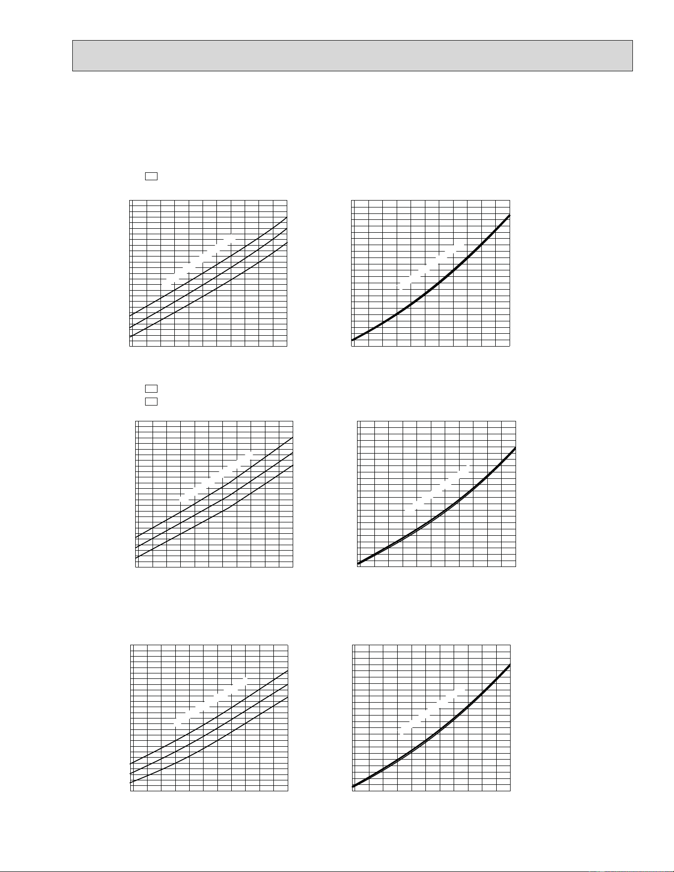
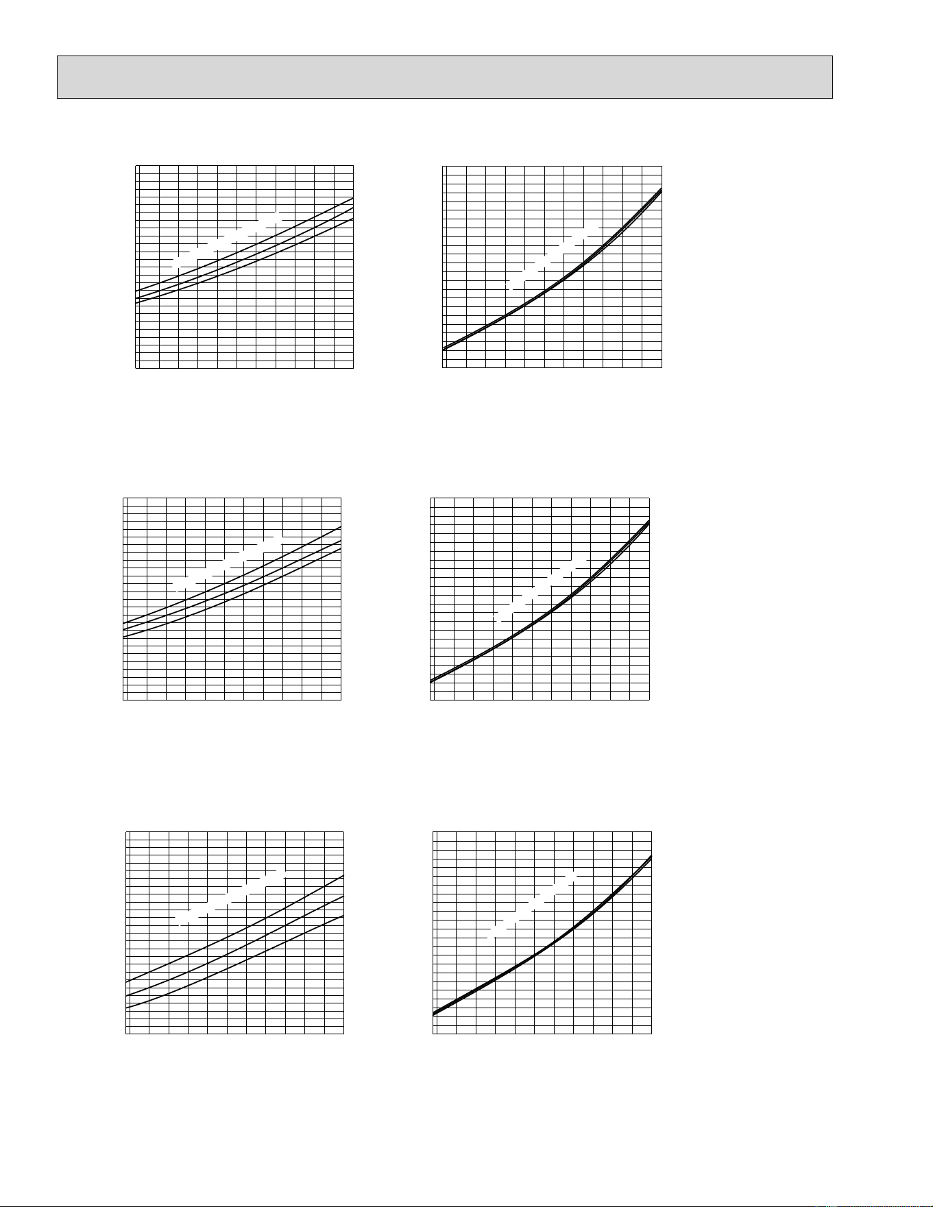
7-5. CAPACITY AND INPUT CORRECTION BY INVERTER OUTPUT FREQUENCY
Correction of Cooling total input
Input correction factors
The operational frequency of compressor
Correction of Cooling capacity
Capacity correction factors
The operational frequency of compressor
Correction of Cooling capacity
Capacity correction factors
The operational frequency of compressor
Correction of Cooling total input
Input correction factors
The operational frequency of compressor
Correction of Heating total input
The operational frequency of compressor
Correction of Heating capacity
Capacity correction factors
The operational frequency of compressor
Correction of Heating total input
Input correction factors
The operational frequency of compressor
Correction of Heating capacity
Capacity correction factors
The operational frequency of compressor
Input correction factors
MUZ-A09NA
MUZ-A09NA -
U1
MUZ-A12NA
0 50 100 150(Hz)
0.0
0.5
1.0
1.5
0 50 100 150(Hz)
0.0
0.5
1.0
1.5
0 50 100 150(Hz)
0.0
0.5
1.0
1.5
2.0
0 50 100 150(Hz)
0.0
0.5
1.0
1.5
2.0
0 50 100 150(Hz)
0.0
0.5
1.0
1.5
0 50 100 150(Hz)
0.0
0.5
1.0
1.5
0 50 100 150(Hz)
0.0
0.5
1.0
1.5
2.0
0 50 100 150(Hz)
0.0
0.5
1.0
1.5
2.0
Capacity correction factors
Input correction factors
Input correction factors
Capacity correction factors
Correction of Cooling capacity
The operational frequency of compressor
Correction of Cooling total input
The operational frequency of compressor
Correction of Heating total input
The operational frequenc
y
of compressor
Correction of Heating capacity
The operational frequenc
y
of compressor
MUY-A15NA
MUZ-A15NA
MUZ-A15NA
0 50 100 150
0.0
0.5
1.0
1.5
(Hz)
0 50 100 150
0.0
0.5
1.0
1.5
(Hz)
0 50 100 150
0.0
0.5
1.0
1.5
(Hz) (Hz)
0 50 100 150
0.0
0.5
1.0
1.5
MUZ-A09NA -
1
MUZ-A09NA - U2
Correction of Cooling total input
Input correction factors
The operational frequency of compressor
Correction of Cooling capacity
Capacity correction factors
The operational frequency of compressor
Correction of Heating total input
The operational frequency of compressor
Correction of Heating capacity
Capacity correction factors
The operational frequency of compressor
Input correction factors
0 50 100 150(Hz)
0.0
0.5
1.0
1.5
0 50 100 150(Hz)
0.0
0.5
1.0
1.5
0 50 100 150(Hz)
0.0
0.5
1.0
1.5
2.0
0 50 100 150(Hz)
0.0
0.5
1.0
1.5
2.0
36
MUY-A24NA
MUZ-A24NA
MUZ-A24NA
Capacity correction factors
Input correction factors
Input correction factors
Capacity correction factors
Correction of Cooling capacity
The operational frequency of compressor
Correction of Cooling total input
The operational frequency of compressor
Correction of Heating total input
The operational frequency of compressor
Correction of Heating capacity
Correction of Heating capacity
The operational frequency of compressor
0 50 100 150
0.0
0.5
1.0
1.5
(Hz)
050100
150
0.0
0.5
1.0
1.5
(Hz)
0 50 100 150
0.0
0.5
1.0
1.5
(Hz)
0 50 100 150
0.0
0.5
1.0
1.5
(Hz)
MUY-GA24NA
MUZ-GA24NA
MUZ-GA24NA
Capacity correction factors
Input correction factors
Input correction factors
Capacity correction factors
Correction of Cooling capacity
The operational frequency of compressor
Correction of Cooling total input
The operational frequency of compressor
Correction of Heating total input
The operational frequency of compressor
The operational frequency of compressor
0 50 100 150
0.0
0.5
1.0
1.5
(Hz)
050100
150
0.0
0.5
1.0
1.5
(Hz)
0 50 100 150
0.0
0.5
1.0
1.5
(Hz)
0 50 100 150
0.0
0.5
1.0
1.5
(Hz)
Capacity correction factors
Input correction factors
Input correction factors
Capacity correction factors
Correction of Cooling capacity
The operational frequency of compressor
Correction of Cooling total input
The operational frequency of compressor
Correction of Heating total input
The operational frequency of compressor
Correction of Heating capacity
The operational frequency of compressor
MUY-A17NA
MUZ-A17NA
MUZ-A17NA
0 50 100 150
0.0
0.5
1.0
1.5
(Hz)
0 50 100 150
0.0
0.5
1.0
1.5
(Hz)
0 50 100 150
0.0
0.5
1.0
1.5
(Hz)
0 50 100 150
0.0
0.5
1.0
1.5
(Hz)
7-6. TEST RUN OPERATION (How to operate fixed-frequency operation)
1. Press EMERGENCY OPERATION switch to COOL or HEAT mode (COOL: Press once, HEAT: Press twice).
2. Test run operation starts and continues to operate for 30 minutes.
3. Compressor operates at rated frequency in COOL mode or 58 Hz in HEAT mode.
4. Indoor fan operates at High speed.
5. After 30 minutes, test run operation finishes and EMERGENCY OPERATION starts (operation frequency of compressor
varies).
6. To cancel test run operation (EMERGENCY OPERATION), press EMERGENCY OPERATION switch or any button on
remote controller.
37
ON
OFF
ON
OFF
Outdoor fan
motor
Compressor
5 seconds 15 seconds
MUZ-A09NA MUZ-A12NA MUZ-A15NA MUZ-A17NA MUZ-A24NA
MUY-A15NA MUY-A17NA MUY-A24NA MUZ-GA24NA MUY-GA24NA
8-3. RELATION BETWEEN MAIN SENSOR AND ACTUATOR
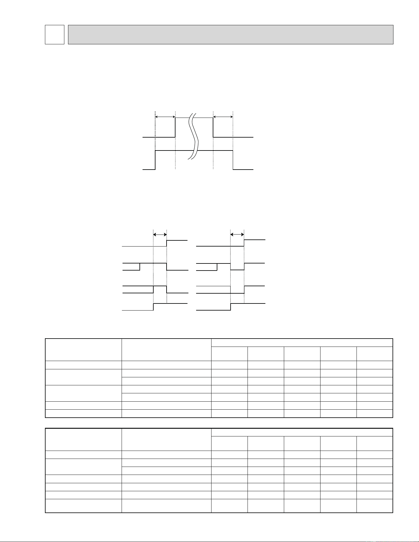
8-2. R.V. COIL CONTROL(MUZ)
Heating
. . . . . . . . . . . . . . . . .
ON
Cooling
. . . . . . . . . . . . . . . . .
OFF
Dry
. . . . . . . . . . . . . . . . . . . .
OFF
NOTE: The 4-way valve reverses for 5 seconds right before start-up of the compressor.
ON
OFF
Compressor
Outdoor fan
motor
R.V.coil
<MUZ-A09/12/15/17>
ON
OFF
ON
OFF
<COOL>
5 seconds
<HEAT>
5 seconds
ON or OFF
ON or OFF
R.V.coil
<MUZ-A24,MUZ-GA24>
ON
OFF
ON or OFF
ON or OFF
8-1. OUTDOOR FAN MOTOR CONTROL
The fan motor turns ON/OFF, interlocking with the compressor.
[ON] The fan motor turns ON 5 seconds before the compressor starts up.
[OFF] The fan motor turns OFF 15 seconds after the compressor has stopped running.
<MUZ-A09/12/15/17, MUY-A15/17>
Sensor Purpose
Actuator
Compressor LEV
Outdoor fan
motor
R.V. coil
Indoor fan
motor
Discharge temperature thermistor
Protection
żż
Indoor coil temperature thermistor
Cooling: Coil frost prevention
ż
Heating: High pressure protection
żż
Defrost thermistor
Cooling: High pressure protection
żż
Heating: Defrosting
żżżżż
Fin temperature thermistor Protection
żż
Ambient temperature thermistor
Cooling: Low ambient temperature operation
żżż
<MUZ-A24, MUY-A24, MUZ-GA24, MUY-GA24>
Sensor Purpose
Actuator
Compressor LEV
Outdoor fan
motor
R.V. coil
Indoor fan
motor
Discharge temperature thermistor
Protection
żż
Indoor coil temperature thermistor
Cooling: Coil frost prevention
ż
Heating: High pressure protection
żż
Defrost thermistor (MUZ) Defrosting
żżżżż
Fin temperature thermistor Protection
żż
Outdoor heat exchanger temperature
High pressure protection
żżż
Ambient temperature thermistor
Cooling: Low ambient temperature
operation
żżż
8
ACTUATOR CONTROL
38
CHANGE IN DEFROST SETTING
<JS> When the JS wire of the outdoor Inverter P.C. board is cut/soldered, the defrost finish temperature is changed.
(Refer to 10-6.1.)
Jumper wire
Defrost ¿ nish temperature °F (°C)
MUZ-A09/12NA MUZ-A15/17NA
JS
Soldered (Initial setting) 50 (10) 41 (5)
None (Cut) 55 (13) 46 (8)
TROUBLESHOOTING
10
10-1. CAUTIONS ON TROUBLESHOOTING
1. Before troubleshooting, check the following
1) Check the power supply voltage.
2) Check the indoor/outdoor connecting wire for miswiring.
2. Take care of the following during servicing
1) Before servicing the air conditioner, be sure to turn OFF the main unit first with the remote controller, and after con-
firming the horizontal vane is closed, turn OFF the breaker and/or disconnect the power plug.
2) Be sure to turn OFF the power supply before removing the front panel, the cabinet, the top panel, and the electronic
control P.C. board.
3) When removing the electrical parts, be careful of the residual voltage of smoothing capacitor.
4) When removing the electronic control P.C. board, hold the edge of the board with care NOT to apply stress on the
components.
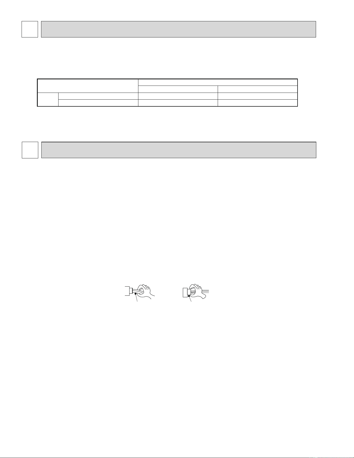
5) When connecting or disconnecting the connectors, hold the housing of the connector. DO NOT pull the lead wires.
Lead wiring
Housing point
Incorrect
Correct
3. Troubleshooting procedure
1) First, check if the OPERATION INDICATOR lamp on the indoor unit is flashing ON and OFF to indicate an abnormal-
ity. To make sure, check how many times the OPERATION INDICATOR lamp is flashing ON and OFF before starting
service work.
2) Before servicing, check that the connector and terminal are connected properly.
3) When the electronic control P.C. board seems to be defective, check the copper foil pattern for disconnection and the
components for bursting and discoloration.
4) Refer to 10-2 and 10-3.
MUZ-A09NA MUZ-A12NA MUZ-A15NA MUZ-A17NA MUZ-A24NA
MUY-A15NA MUY-A17NA MUY-A24NA MUZ-GA24NA MUY-GA24NA
MUZ-A09NA MUZ-A12NA MUZ-A15NA MUZ-A17NA
SERVICE FUNCTIONS
9
39
This figures show about MSZ-A09/12/15/17.
Outline of the function
This air conditioner can memorize the abnormal condition which has occurred once.
Even though LED indication listed on the troubleshooting check table (10-3.) disappears, the memorized failure details
can be recalled.
This mode is very useful when the unit needs to be repaired for the abnormality which does not recur.
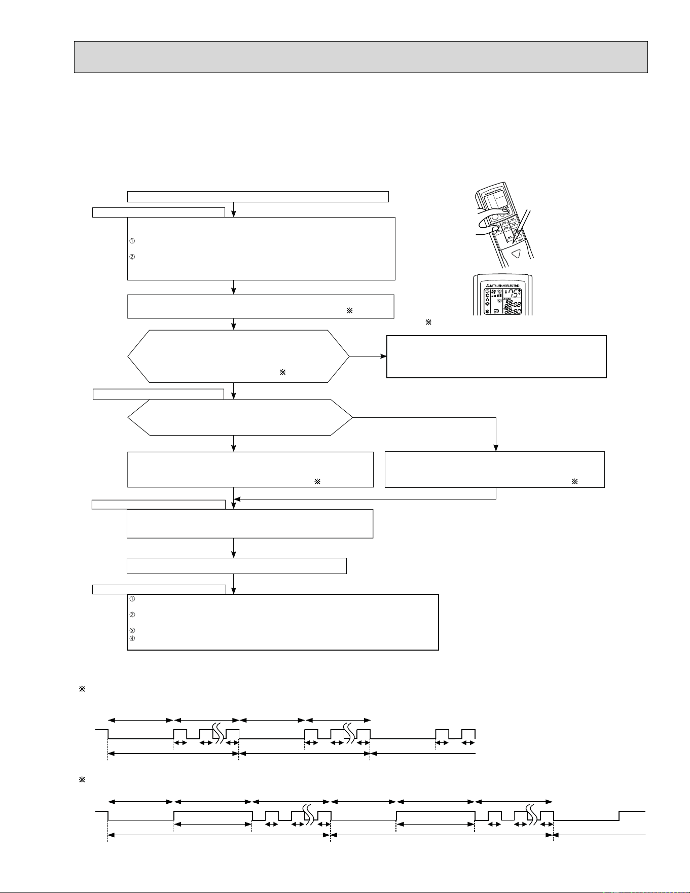
10-2. FAILURE MODE RECALL FUNCTION
1. Flow chart of failure mode recall function for the indoor/outdoor unit
2. Blinking pattern when the indoor unit is abnormal:
3.Blinking pattern when the outdoor unit is abnormal:
ON
OFF
Beeps
Repeated cycle Repeated cycle
ON
OFF
No beep Beeps
Repeated cycle
2.5-second OFF
Blinking at 0.5-
second interval
2.5-second OFF 3-second ON
Blinking at 0.5-
second interval
Beeps
Repeated cycle
2.5-second OFF
Blinking at 0.5-
second interval
No beep Beeps
Repeated cycle
2.5-second OFF 3-second ON
Blinking at 0.5-
second interval
Repeated cycle
Beeps
Does the left lamp of OPERATION INDICATOR lamp on the
indoor unit blink at the interval of 0.5 seconds?
Blinks: Either indoor or outdoor unit is abnormal. Beep is emit-
ted at the same timing as the blinking of the left lamp
of OPERATION INDICATOR lamp. 2
Indoor unit is normal.
But the outdoor unit might be abnormal because there are some abnor-
malities that can not be recalled with this way.
Con¿ rm if outdoor unit is abnormal according to the detailed outdoor
unit failure mode recall function. (Refer to 10-2.2)
No
Yes
The cause of abnormality cannot be found because the abnormality does not recur.
Setting up the failure mode recall function
Turn ON the power supply.
<Preparation of the remote controller>
While pressing both OPERATION SELECT button and TOO COOL button on the
remote controller at the same time, press RESET button.
First, release RESET button.
Hold down the other two buttons for another 3 seconds. Con¿ rm that the indicators on
the LCD screen shown in the right ¿ gures are all displayed. Then release the buttons.
Press OPERATE/STOP (ON/OFF) button of the remote controller (the set temperature
is displayed) with the remote controller headed towards the indoor unit. 1
Judgment of indoor/outdoor abnormality
Before blinking, does the left lamp of OPERATION INDICA-
TOR lamp stay ON for 3 seconds?
Stays ON for 3 seconds (without beep):
The outdoor unit is abnormal.
The indoor unit is abnormal.
Check the blinking pattern, and con¿ rm the abnormal point with the indoor unit
failure mode table. (Refer to indoor unit service manual.)
Make sure to check at least two consecutive blinking cycles. 2
Releasing the failure mode recall function
Release the failure mode recall function by the following procedures.
Turn OFF the power supply and turn it ON again.
Press RESET button of the remote controller.
The outdoor unit is abnormal.
Check the blinking pattern, and con¿ rm the abnormal point with the
outdoor unit failure mode table. (Refer to 10-2.3)
Make sure to check at least two consecutive blinking cycles. 3
Repair the defective parts.
Deleting the memorized abnormal condition
After repairing the unit, recall the failure mode again according to "Setting up the failure mode recall
function" mentioned above.
Press OPERATE/STOP (ON/OFF) button of the remote controller (the set temperature is displayed)
with the remote controller headed towards the indoor unit.
Press EMERGENCY OPERATION switch so that the memorized abnormal condition is deleted.
Release the failure mode recall function according to "Releasing the failure mode recall function"
mentioned above.
Operational procedure
Yes
(Blinks)
No
(OFF)
NOTE: 1. Make sure to release the failure mode recall function once it is set up, otherwise the unit cannot operate properly.
2. If the abnormal condition is not deleted from the memory, the last abnormal condition is kept memorized.
1. Regardless of normal or abnormal condition, a short
beep is emitted once the signal is received.
40
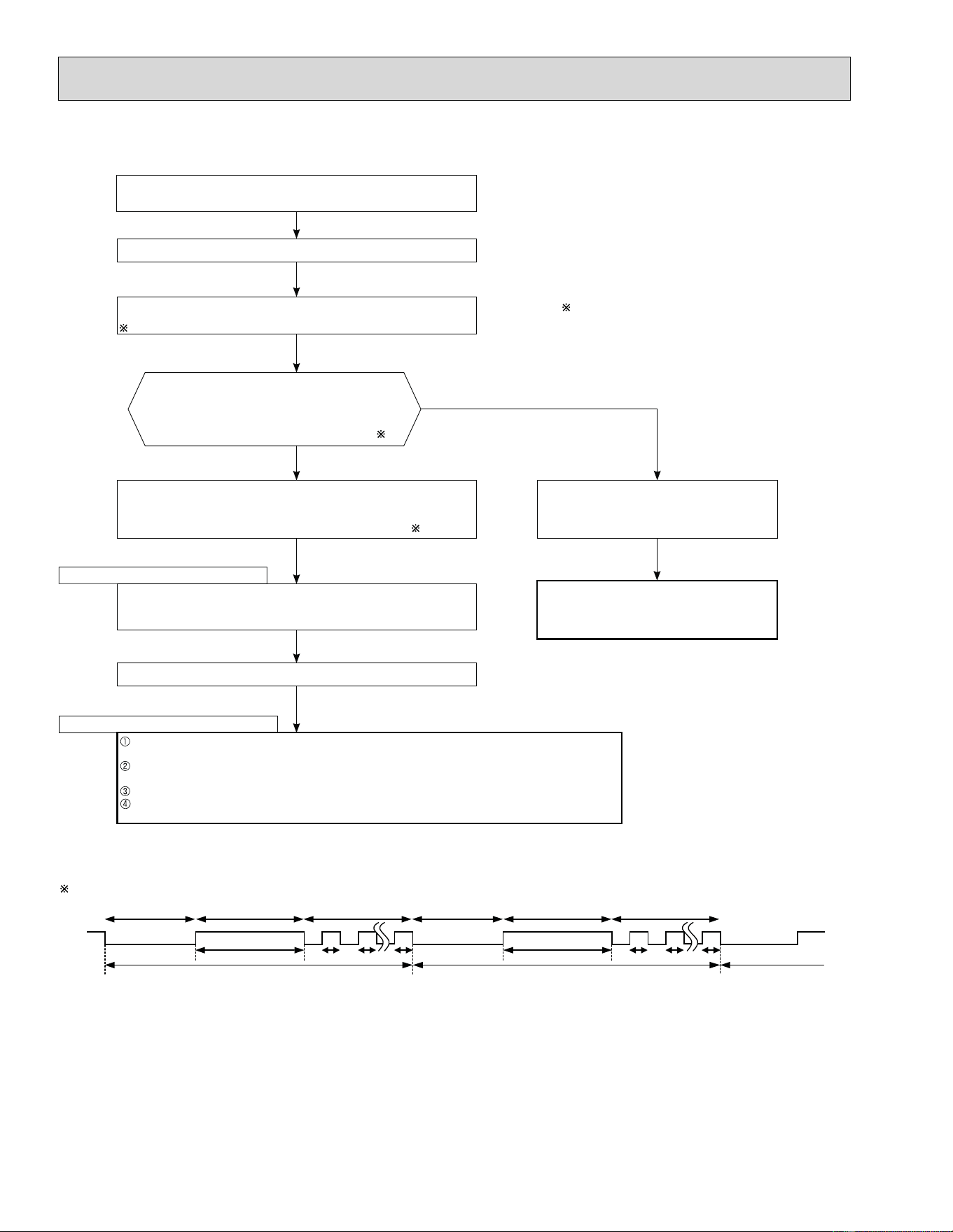
Does left lamp of OPERATION INDICATOR lamp on
the indoor unit blink at the interval of 0.5 seconds?
Blinks: The outdoor unit is abnormal. Beep is emitted
at the same timing as the blinking of the left
lamp of OPERATION INDICATOR lamp.
2
Yes
(Blinks
)
No
(OFF)
The outdoor unit might be abnormal.
Con¿ rm if outdoor unit is abnormal according to the following procedures.
Operational procedure
Con¿ rm that the remote controller is in the failure mode recall function.
With the remote controller headed towards the indoor unit, press TOO
COOL or TOO WARM button to adjust the set temperature to 77ÛF (25ÛC).
1
1. Regardless of normal or abnormal condition, 2 short
beeps are emitted as the signal is received.
The outdoor unit is abnormal.
Check the blinking pattern, and con¿ rm the abnormal point with the out-
door unit failure mode table. (10-2.3.)
Make sure to check at least two consecutive blinking cycles. 2
Releasing the failure mode recall function
Release the failure mode recall function by the following procedures.
Turn OFF the power supply and turn it ON again.
Press RESET button of the remote controller.
Repair the defective parts.
The outdoor unit is normal.
Release the failure mode recall function accord-
ing to the left mentioned procedure.
Deleting the memorized abnormal condition
After repairing the unit, recall the failure mode again according to "Setting up the failure mode recall
function" (10-2.1.).
Press OPERATE/STOP (ON/OFF) button of the remote controller (the set temperature is displayed)
with the remote controller headed towards the indoor unit.
Press EMERGENCY OPERATION switch so that the memorized abnormal condition is deleted.
Release the failure mode recall function according to "Releasing the failure mode recall function"
mentioned above.
NOTE: 1. Make sure to release the failure mode recall function once it is set up, otherwise the unit cannot operate properly.
2. If the abnormal condition is not deleted from the memory, the last abnormal condition is kept memorized.
2. Flow chart of the detailed outdoor unit failure mode recall function
2.Blinking pattern when outdoor unit is abnormal:
ON
OFF
No beep
Beeps
Repeated cycle
2.5-second OFF 3-second ON
Blinking at 0.5-
second interval
No beep Beeps
Repeated cycle
2.5-second OFF 3-second ON
Blinking at 0.5-
second interval
Repeated cycle
41
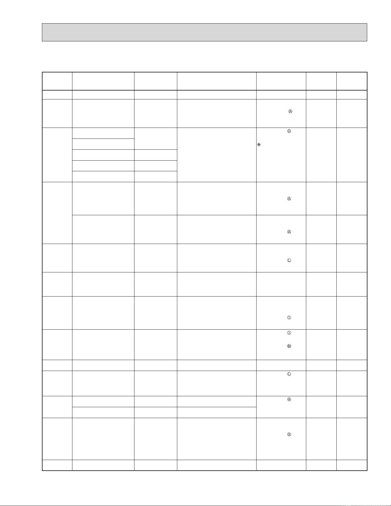
3. Outdoor unit failure mode table
MUZ-A09/12/15/17NA MUY-A15/17NA
The left lamp of
OPERATION INDICATOR
lamp (Indoor unit)
Abnormal point
(Failure mode/protection)
LED indication
(Outdoor P.C. board)
Condition Remedy
Indoor/outdoor
unit failure
mode recall
function
Outdoor unit
failure mode
recall function
OFF None (Normal)
—— ———
2-time À ash
2.5 seconds OFF
Outdoor power system
—
Overcurrent protection stop is
continuously performed 3 times within
1 minute after the compressor gets
started.
• Reconnect
connectors.
• Refer to 10-5.
"How
to check inverter/
compressor".
• Check stop valve.
żż
3-time À ash
2.5 seconds OFF
Discharge temperature
thermistor
1-time À ash every
2.5 seconds
Thermistor shorts or opens during
compressor running.
• Refer to 10-5.
"Check of outdoor
thermistors".
Defective outdoor
thermistors can be
identi¿ ed by checking
the blinking pattern of
LED.
żż
Defrost thermistor (MSZ)
Fin temperature thermistor 3-time À ash
2.5 seconds OFF
P.C. board temperature
thermistor
4-time À ash
2.5 seconds OFF
Ambient temperature
thermistor
2-time À ash
2.5 seconds OFF
4-time À ash
2.5 seconds OFF
Overcurrent 11-time À ash
2.5 seconds OFF
24 A (09/12) / 26.5 A (15/17) current
À ows into intelligent power module.
• Reconnect
compressor
connector.
• Refer to 10-5. "How
to check inverter/
compressor".
• Check stop valve.
—
ż
Compressor synchronous
abnormality (Compressor
start-up failure protection)
12-time À ash
2.5 seconds OFF
Waveform of compressor current is
distorted.
• Reconnect
compressor
connector.
• Refer to 10-5.
"How
to check inverter/
compressor".
—
ż
5-time À ash
2.5 seconds OFF
Discharge temperature
—
Temperature of discharge temperature
thermistor exceeds 241°F (116°C),
compressor stops.
Compressor can restart if discharge
temperature thermistor reads 212°F
(100°C) or less 3 minutes later.
• Check refrigerant
circuit and refrigerant
amount.
• Refer to 10-5.
"Check of LEV".
—
ż
6-time À ash
2.5 seconds OFF
High pressure
—
Indoor coil thermistor temperature
exceeds 158°F (70°C) in HEAT mode.
(MUZ)
Defrost thermistor exceeds 158°F (70°
C) in COOL mode.
• Check refrigerant
circuit and refrigerant
amount.
• Check stop valve.
—
ż
7-time À ash
2.5 seconds OFF
Fin temperature / P.C. board
temperature
7-time À ash
2.5 seconds OFF
Temperature of ¿ n temperature
thermistor on the inverter P.C. board
exceeds 180°F (82°C) (09/12) /188°
F (86.5°C) (15/17), or temperature of
P.C. board temperature thermistor on
the inverter P.C. board exceeds 176°F
(80°C).
• Check around outdoor
unit.
• Check outdoor unit air
passage.
• Refer to 10-5.
"Check of outdoor fan
motor".
—
ż
8-time À ash
2.5 seconds OFF
Outdoor fan motor
—
Outdoor fan has stopped 3 times in a
row within 30 seconds after outdoor
fan start-up.
• Refer to 10-5.
"Check of outdoor fan
motor".
• Refer to 10-5.
"Check of inverter P.C.
board".
—
ż
9-time À ash
2.5 seconds OFF
Nonvolatile memory data 5-time À ash
2.5 seconds OFF
Nonvolatile memory data cannot be
read properly.
• Replace the inverter
P.C. board.
żż
10-time À ash
2.5 seconds OFF
Discharge temperature
—
Temperature of discharge temperature
thermistor has been 122°F (50°C) or
less for 20 minutes.
• Refer to 10-5.
"Check of LEV".
• Check refrigerant
circuit and refrigerant
amount.
—
ż
11-time À ash
2.5 seconds OFF
DC voltage 8-time À ash
2.5 seconds OFF
DC voltage of inverter cannot be
detected normally.
• Refer to 10-5. "How
to check inverter/
compressor".
—
ż
Each phase current of
compressor
9-time À ash
2.5 seconds OFF
Each phase current of compressor
cannot be detected normally.
12-time À ash
2.5 seconds OFF
Overcurrent
Compressor open-phase
10-time À ash
2.5 seconds OFF
24 A (09/12) / 26.5 A (15/17) current
À ows into intelligent power module
(IPM).
The open-phase operation of
compressor is detected.
The interphase short out occurs in the
output of the intelligent power module
(IPM).
The compressor winding shorts out.
• Reconnect
compressor
connector.
• Refer to 10-5. "How
to check inverter/
compressor"
—
ż
14-time À ash
2.5 seconds OFF
Outdoor unit
(Other abnormality)
—
The inverter P.C. board is defective. • Replace the inverter
P.C. board.
—
ż
NOTE: Blinking patterns of this mode differ from the ones of Troubleshooting check table (10-3.).
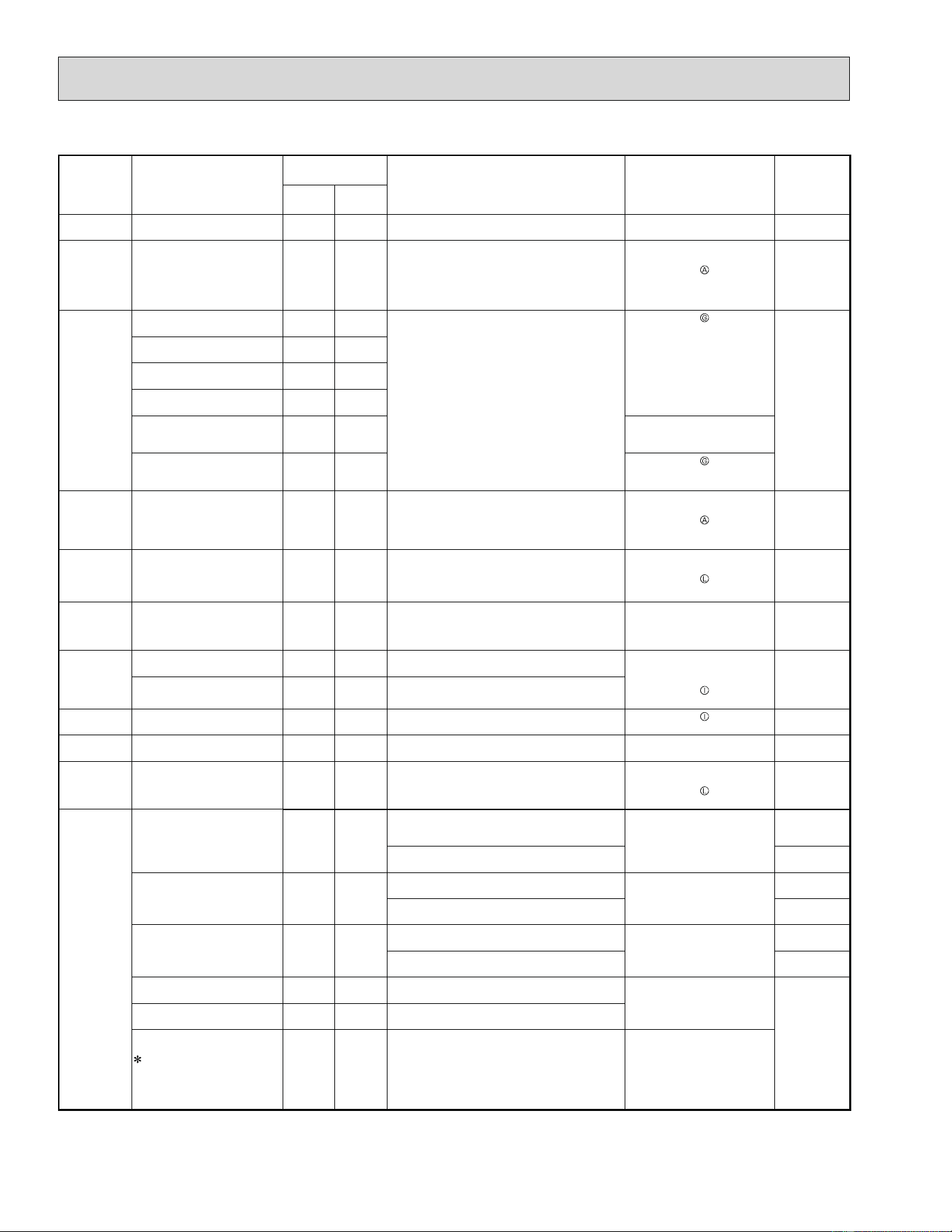
42
MUZ-A24NA MUY-A24NA MUZ-GA24NA MUY-GA24NA
The left lamp of
OPERATION INDICATOR
lamp (Indoor unit)
Abnormal point
(Failure mode/protection)
LED indication
(Outdoor P.C. board)
Condition Remedy
Indoor/outdoor
unit failure
mode recall
function
LED1 LED2
OFF None (Normal)
Lighting Lighting — — —
2-time À ash
Outdoor power system Lighting Lighting IPM protection stop or lock protection stop is
continuously performed 3 times within 1 minute
after the compressor gets started, or converter
protection stop or bus-bar voltage protection
stop is continuously performed 3 times within 3
minutes after start-up.
• Check the connection of the
compressor connecting wire.
• Refer to 10-5. "How to
check inverter/compressor".
• Check the stop valve.
ż
3-time À ash
Discharge temperature
thermistor
Lighting Once Thermistor shorts or opens during compressor
running.
• Refer to 10-5. "Check of
outdoor thermistors".
ż
Defrost thermistor (MUZ) Lighting Once
Ambient temperature
thermistor
Lighting Twice
Fin temperature thermistor Lighting 3 times
P.C. board temperature
thermistor
Lighting 4 times • Replace the outdoor
electronic control P.C. board.
Outdoor heat exchanger
temperature thermistor
Lighting 9 times • Refer to 10-5. "Check of
outdoor thermistors".
4-time À ash
Overcurrent Once Goes out 28 A current À ows into intelligent power module. • Reconnect compressor
connector.
• Refer to 10-5.
"How to
check inverter/compressor.
• Check the stop valve.
—
5-time À ash
Discharge temperature Lighting Lighting Discharge temperature exceeds 241°F (116°
C) during operation. Compressor can restart if
discharge temperature thermistor reads 212°F
(100°C) or less 3 minutes later.
• Check refrigerant circuit and
refrigerant amount.
• Refer to 10-5. "Check of
LEV".
—
6-time À ash
High pressure Lighting Lighting The outdoor heat exchanger temperature
exceeds 158°F (70°C) during cooling or the
indoor gas pipe temperature exceeds 158°F (70
°C) during heating.
• Check refrigerant circuit and
refrigerant amount.
• Check the stop valve.
—
7-time À ash
Fin temperature 3 times Goes out The ¿ n temperature exceeds 189°F (87°C)
during operation.
• Check around outdoor unit.
• Check outdoor unit air
passage.
• Refer to 10-5.
"Check of
outdoor fan motor".
—
P.C. board temperature 4 times Goes out The P.C. board temperature exceeds 158°F (70°
C) during operation.
8-time À ash
Outdoor fan motor Lighting Lighting Failure occurs continuously three times within
30 seconds after the fan gets started.
• Refer to 10-5. "Check of
outdoor fan motor".
—
9-time À ash
Nonvolatile memory data Lighting 5 times Nonvolatile memory data cannot be read
properly.
• Replace the outdoor
electronic control P.C. board.
ż
10-time À ash
Discharge temperature Lighting Lighting The frequency of the compressor is kept 80 Hz
or more and the discharge temperature is kept
under 102°F (39°C) for more than 20 minutes.
• Check refrigerant circuit and
refrigerant amount.
• Refer to 10-5.
"Check of
LEV".
—
11-time À ash Communication error between
P.C. boards
Lighting 6 times Communication error occurs between the
electronic control P.C. board and power board
for more than 10 seconds.
•
Check the connecting wire
between outdoor electronic
control P.C. board and
power board.
—
The communication between boards protection
stop is continuously performed twice.
ż
Current sensor Lighting 7 times A short or open circuit is detected in the current
sensor during compressor operating.
•
Replace the power board.
—
Current sensor protection stop is continuously
performed twice.
ż
Zero cross detecting circuit 5 times Goes out Zero cross signal cannot be detected while the
compressor is operating.
•
Check the connecting wire
among electronic control
P.C. board, noise ¿ lter P.C.
board and power board.
—
The protection stop of the zero cross detecting
circuit is continuously performed 10 times.
ż
Converter 5 times Goes out A failure is detected in the operation of the
converter during operation.
• Check the voltage of power
supply.
•
Replace the power board.
—
Bus-bar voltage
(1)
5 times Goes out The bus-bar voltage exceeds 400 V or falls to
200 V or below during compressor operating.
Bus-bar voltage
(2)
Even if this protection stop
is performed continuously
3 times, it does not mean
the abnormality in outdoor
power system.
6 times Goes out The bus-bar voltage exceeds 400 V or falls to 50
V or below during compressor operating.
• Check the voltage of power
supply.
• Replace the outdoor
electronic control P.C. board.
NOTE: Blinking patterns of this mode differ from the ones of TROUBLESHOOTING CHECK TABLE (10-3.).
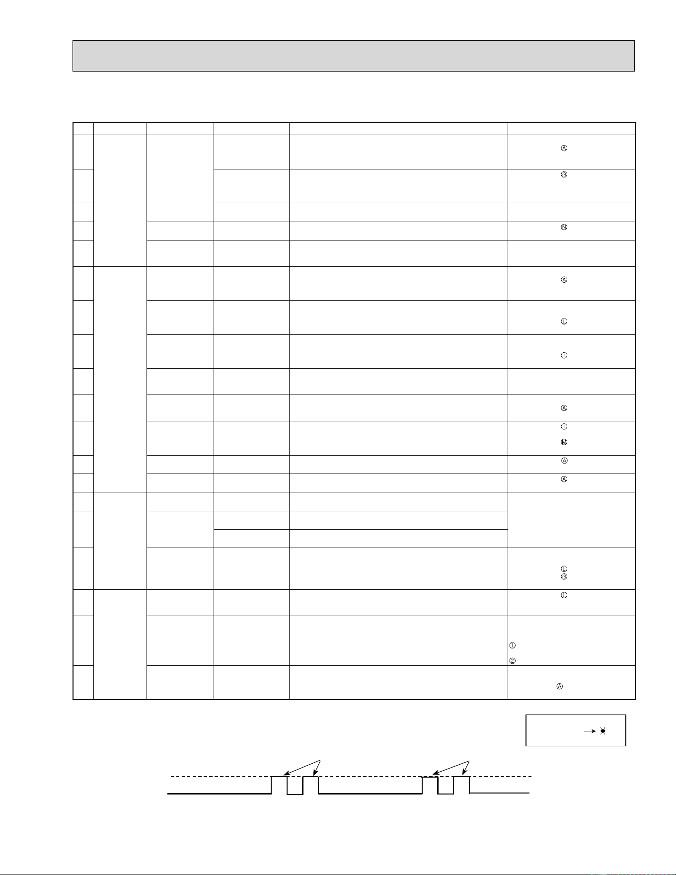
43
MUZ-A09/12/15/17NA MUY-A15/17NA
No. Symptom LED indication
Abnormal point/Condition
Condition Remedy
1
Outdoor unit
does not oper-
ate.
1-time À ash every
2.5 seconds
Outdoor power sys-
tem
Overcurrent protection stop is continuously performed 3 times
within 1 minute after the compressor gets started.
•
Reconnect connector of compressor.
•
Refer to 10-5. "How to check in-
verter/compressor".
•
Check stop valve.
2
Outdoor thermistors Discharge temperature thermistor, ¿ n temperature thermistor,
defrost thermistor (MUZ), P.C. board temperature thermistor or
ambient temperature thermistor shorts or opens during com-
pressor running.
•
Refer to 10-5. "Check of outdoor
thermistors".
3
Outdoor control sys-
tem
Nonvolatile memory data cannot be read properly. Replace inverter P.C. board.
4
6-time À ash
2.5 seconds OFF
Serial signal The communication fails between the indoor and outdoor unit
for 3 minutes.
•
Refer to 10-5. "How to check
miswiring and serial signal error".
5
14-time À ash
2.5 seconds OFF
Outdoor unit
(Other abnormality)
Outdoor unit is defective. Refer to 10-2.2. "Flow chart of the
detailed outdoor unit failure mode
recall function".
6
'Outdoor unit
stops and
restarts 3 min-
utes later' is
repeated.
2-time À ash
2.5 seconds OFF
Overcurrent protec-
tion
24 A (09/12) / 26.5 A (15/17) current À ows into intelligent power
module.
• Reconnect connector of compressor.
•
Refer to 10-5. "How to check in-
verter/compressor"
•
Check stop valve.
7
3-time À ash
2.5 seconds OFF
Discharge tempera-
ture overheat protec-
tion
Temperature of discharge temperature thermistor exceeds 241
°F (116°C) compressor stops. Compressor can restart if dis-
charge temperature thermistor reads 212°F (100°C) or less 3
minutes later.
•
Check refrigerant circuit and refrig-
erant amount.
•
Refer to 10-5. "Check of LEV".
8
4-timeÀ ash
2.5 seconds OFF
Fin temperature/
P.C. board tempera-
ture thermistor over-
heat protection
Temperature of ¿ n temperature thermistor on the heat sink
exceeds 180°F (82°C) (09/12) / 188°F (86.5°C) (15/17) or tem-
perature of P.C. board temperature thermistor on the inverter
P.C. board exceeds 176°F (80°C).
•
Check around outdoor unit.
•
Check outdoor unit air passage.
•
Refer to 10-5. "Check of outdoor
fan motor".
9
5-time À ash
2.5 seconds OFF
High pressure pro-
tection
Indoor coil thermistor exceeds 158°F (70°C) in HEAT mode.
(MUZ)
Defrost thermistor exceeds 158°F (70°C) in COOL mode.
•
Check refrigerant circuit and refrig-
erant amount.
•
Check stop valve.
10
8-time À ash
2.5 seconds OFF
Compressor syn-
chronous abnormal-
ity
The waveform of compressor current is distorted.
•
Reconnect connector of compressor.
•
Refer to 10-5. "How to check in-
verter/compressor"
11
10-time À ash
2.5 seconds OFF
Outdoor fan motor Outdoor fan has stopped 3 times in a row within 30 seconds
after outdoor fan start-up.
•
Refer to 10-5. "Check of outdoor
fan motor".
•
Refer to 10-5. "Check of inverter
P.C. board".
12
12-timeÀ ash
2.5 seconds OFF
Each phase current
of compressor
Each phase current of compressor cannot be detected nor-
mally.
• Refer to 10-5.
"How to check
inverter/compressor"
13
13-time À ash
2.5 seconds OFF
DC voltage DC voltage of inverter cannot be detected normally.
•
Refer to 10-5. "How to check in-
verter/compressor".
14
Outdoor unit
operates.
1-time À ash
2.5 seconds OFF
Frequency drop by
current protection
Current from power outlet exceeds 9.2 A (09/12) / 11.1 A
(15/17) compressor frequency lowers.
The unit is normal, but check the fol-
lowing.
•
Check if indoor ¿ lters are clogged.
•
Check if refrigerant is short.
•
Check if indoor/outdoor unit air cir-
culation is short cycled.
15
3-time À ash
2.5 seconds OFF
Frequency drop by high
pressure protection
Temperature of indoor coil thermistor exceeds 131°F (55°C) in
HEAT mode (MUZ), compressor frequency lowers.
Frequency drop by de-
frosting in COOL mode
Indoor coil thermistor reads 46°F (8°C) or less in COOL mode,
compressor frequency lowers.
16
4-time À ash
2.5 seconds OFF
Frequency drop by
discharge tempera-
ture protection
Temperature of discharge temperature thermistor exceeds 232
°F (111°C), compressor frequency lowers.
•
Check refrigerant circuit and refrig-
erant amount.
•
Refer to 10-5. "Check of LEV".
•
Refer to 10-5. "Check of outdoor
thermistors".
17
Outdoor unit
operates.
7-time À ash
2.5 seconds OFF
Low discharge tem-
perature protection
Temperature of discharge temperature thermistor has been
122°F (50°C) or less for 20 minutes.
•
Refer to 10-5. "Check of LEV".
•
Check refrigerant circuit and refrig-
erant amount.
18
8-time À ash
2.5 seconds OFF
PAM protection
PAM:
Pulse
Amplitude
Modulation
The overcurrent À ows into IGBT (Insulated Gate Bipolar tran-
sistor: TR821) or when the bus-bar voltage reaches 320 V or
more, PAM stops and restarts.
This is not malfunction.
PAM protection will be activated in
the following cases:
lnstantaneous power voltage drop
(Short time power failure)
When the power supply voltage is high.
19
9-time À ash
2.5 seconds OFF
Inverter check mode The connector of compressor is disconnected, inverter check
mode starts.
Check if the connector of the com-
pressor is correctly connected.
Refer to 10-5. "How to check in-
verter/compressor".
NOTE: 1. The location of LED is illustrated at the right ¿ gure. Refer to 10-6.1.
2. LED is lighted during normal operation.
The À ashing frequency shows the number of times the LED blinks after every 2.5-second OFF.
(Example) When the À ashing frequency is "2".
Inverter P.C. board (Parts side)
LED
Flashing
ON
OFF
2.5-second OFF
2.5-second OFF
0.5-second ON 0.5-second ON
10-3. TROUBLESHOOTING CHECK TABLE
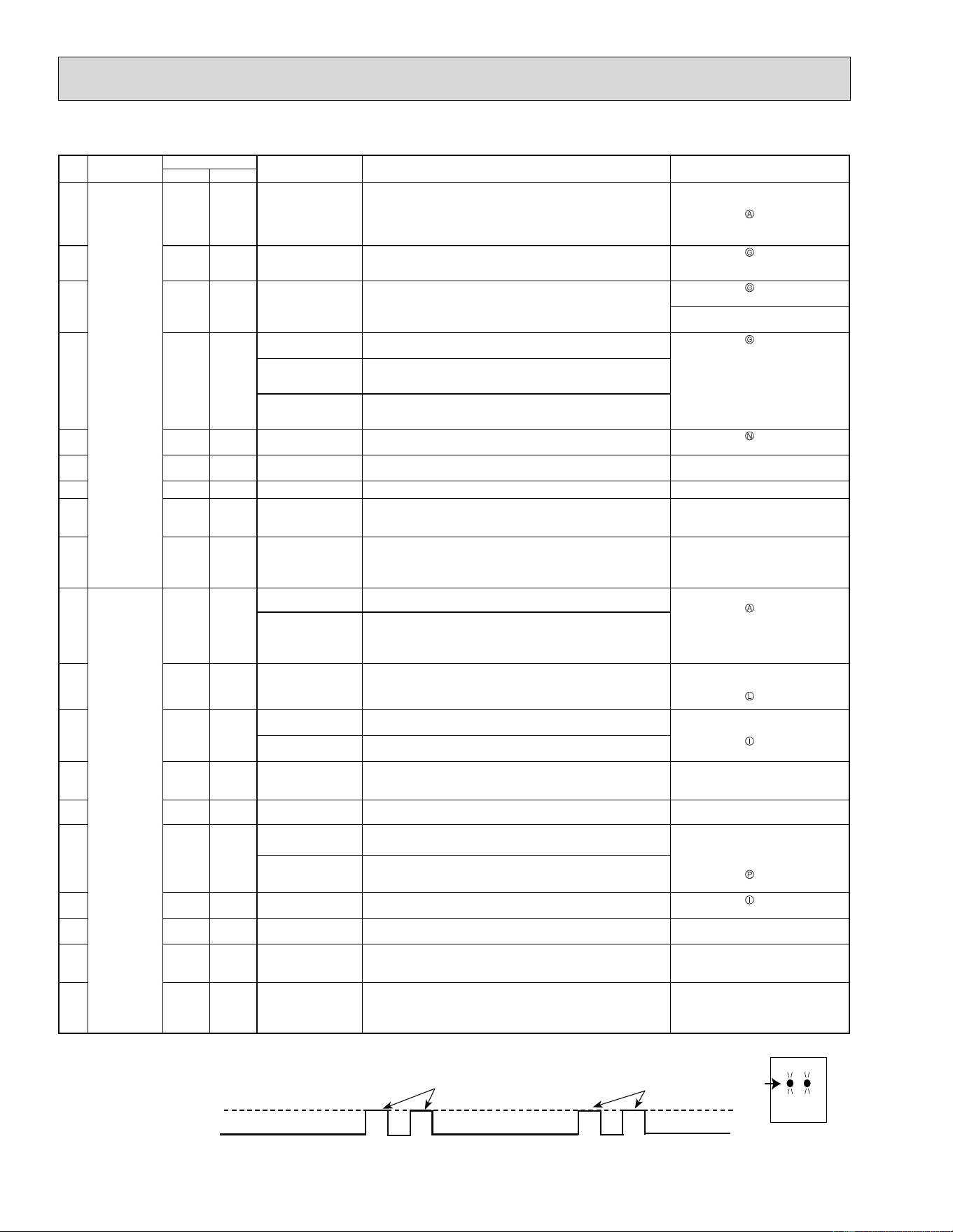
44
MUZ-A24NA MUY-A24NA MUZ-GA24NA MUY-GA24NA
No. Symptom
LED indication
Abnormal point/
Condition
Condition Remedy
LED1(Red)
LED2(Yellow)
1
Outdoor unit
does not oper-
ate.
Lightning
Twice
Outdoor power system
Overcurrent protection stop is continuously performed 3 times
within 1 minute after the compressor gets started, or converter
protection stop or bus-bar voltage protection stop is continu-
ously performed 3 times within 3 minutes after start-up.
• Check the connection of the com-
pressor connecting wire.
• Refer to 10-5. "How to check in-
verter/compressor".
• Check the stop valve.
2
Lightning
3 times
Discharge temperature
thermistor
A short circuit is detected in the thermistor during operation, or
when an open circuit is detected in the thermistor after 10 min-
utes of compressor start-up.
• Refer to 10-5.
"Check of outdoor
thermistors".
3
Lightning
4 times
Fin temperature ther-
mistor
A short or open circuit is detected in the thermistor during op-
eration.
• Refer to 10-5.
"Check of outdoor
thermistors".
• Replace the outdoor electronic
control P.C. board.
4
Lightning
5 times
Ambient temperature
thermistor
A short or open circuit is detected in the thermistor during op-
eration.
• Refer to 10-5.
"Check of outdoor
thermistors".
Outdoor heat exchanger
temperature thermistor
A short circuit is detected in the thermistor during operation, or
an open circuit is detected in the thermistor after 5 minutes (in
cooling) and 10 minutes (in heating) of compressor start-up.
Defrost thermistor
(MUZ)
A short circuit is detected in the thermistor during operation, or
an open circuit is detected in the thermistor after 5 minutes of
compressor stat-up.
5
Lightning
6 times
Serial signal The communication fails between the indoor and outdoor unit 3
minutes.
• Refer to 10-5.
"How to check
miswiring and serial signal error.
6
Lightning
7 times
Nonvolatile memory
data
The nonvolatile memory data cannot be read properly. • Replace the outdoor electronic
control P.C. board.
7
Lightning
8 times
Current sensor Current sensor protection stop is continuously performed twice. • Replace the power board.
8
Lightning
11 times
Communication error
between P.C. boards
The communication protection stop between boards is continu-
ously performed twice.
• Check the connecting wire be-
tween outdoor electronic control
P.C. board and power board.
9
Lightning
12 times
Zero cross detecting
circuit
The protection stop of the zero cross detecting circuit is con-
tinuously performed 10 times.
• Check the connecting wire among
outdoor electronic control P.C.
board, noise ¿ lter P.C. board and
power board.
10
'Outdoor unit
stops and
restarts 3 min-
utes later' is
repeated.
Twice Goes out
lPM protection Overcurrent is detected after 30 seconds of compressor start-
up.
• Reconnect compressor connector.
• Refer to 10-5.
"How to check in-
verter/compressor".
• Check the stop valve.
• Check the power module (PAM
module).
Lock protection Overcurrent is detected within 30 seconds of compressor start-
up.
11 3 times Goes out
Discharge tempera-
ture protection
Discharge temperature exceeds 241°F (116°C) during opera-
tion and compressor stops. Compressor can restart if discharge
temperature thermistor reads 212°F (100°C) or less 3 minutes
later.
• Check the amount of gas and re-
frigerant circuit.
• Refer to 10-5. "Check of LEV".
12 4 times Goes out
Fin temperature pro-
tection
The ¿ n temperature exceeds 189°F (87°C) during operation. • Check around outdoor unit.
• Check outdoor unit air passage.
• Refer to 10-5. "Check of outdoor
fan motor".
P.C. board temperature
protection
The P.C. board temperature exceeds 158°F (70°C) during op-
eration.
13 5 times Goes out
High-Pressure pro-
tection
The outdoor heat exchanger temperature exceeds 158°F (70°
C) during cooling or indoor gas pipe temperature exceeds 158°
F (70°C) during heating (MUZ).
• Check the amount of gas and the
refrigerant circuit.
• Check the stop valve.
14 8 times Goes out
Converter protection A failure is detected in the operation of the converter during op-
eration.
• Replace the power board.
15 9 times Goes out
Bus-bar voltage pro-
tection (1)
The bus-bar voltage exceeds 400 V or falls to 200 V or below
during compressor operating.
• Check the voltage of power supply.
• Replace the power board or the
outdoor electronic control P.C.
board.
• Refer to 10-5. "Check of bus-bar
voltage".
Bus-bar voltage pro-
tection (2)
The bus-bar voltage exceeds 400 V or falls to 50 V or below
during compressor operating.
16 13 times Goes out
Outdoor fan motor Failure occurs continuously three times within 30 seconds after
the fan gets started.
• Refer to 10-5. "Check of outdoor
fan motor".
17 Lighting 8 times
Current sensor pro-
tection
A short or open circuit is detected in the current sensor during
compressor operating.
• Replace the power board.
18 Lighting 11 times
Communication be-
tween P.C. boards
protection
Communication error occurs between the outdoor electronic
control P.C. board and power board for more than 10 seconds
• Check the connecting wire be-
tween outdoor electronic control
P.C. board and power board.
19 Lighting 12 times
Zero cross detecting
circuit protection
Zero cross signal cannot be detected while the compressor is
operating.
• Check the connecting wire among
outdoor electronic control P.C.
board, noise ¿ lter P.C. board and
power board.
NOTE: 1. The location of LED is illustrated at the right ¿ gure. Refer to 10-6.3.
2. LED is lighted during normal operation.
The À ashing frequency shows the number of times the LED blinks after every 2.5-second OFF.
(Example) When the À ashing frequency is “2”.
Outdoor electronic control P.C. board(Parts side)
Lighting
LED2
LED1
The flashing frequency shows the number of times the LED blinks after every 2.5-second OFF.
(Example) When the flashing frequency is “2”.
ON
OFF
2.5-second OFF
2.5-second OFF
0.5-second ON
0.5-second ON
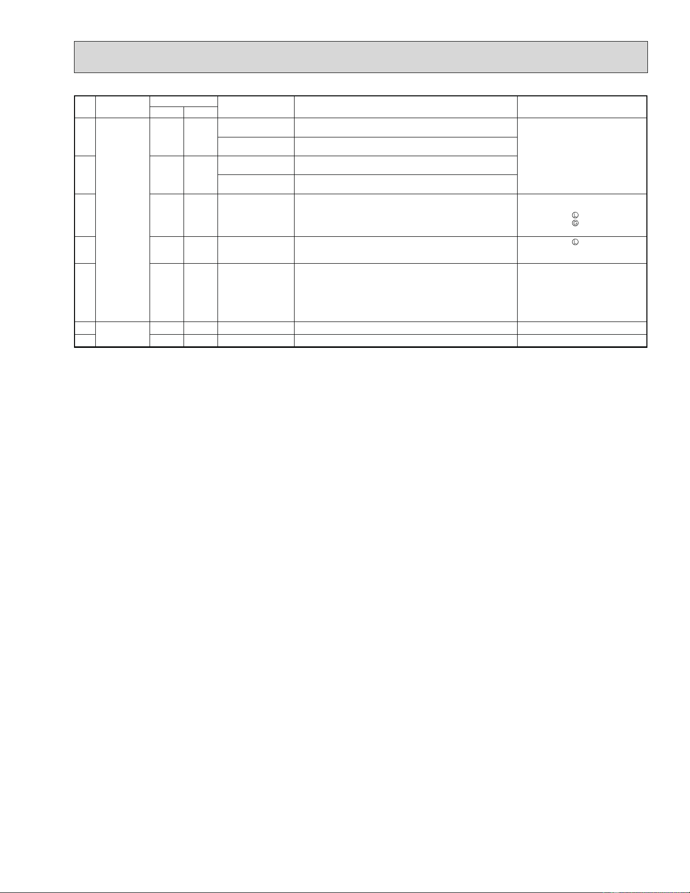
45
No. Symptom
LED indication
Abnormal point/
Condition
Condition Remedy
LED1(Red)
LED2(Yellow)
20
Outdoor unit
operates.
Once
Lighting
Primary current pro-
tection
The input current exceeds 15 A. These symptoms do not mean any
abnormality of the product, but
check the following points.
• Check if indoor ¿ lters are clogged.
• Check if refrigerant is short.
• Check if indoor/outdoor unit air
circulation is short cycled.
Secondary current pro-
tection
The current of the compressor exceeds 15 A.
21
Twice
Lighting
High-Pressure protec-
tion (MUZ)
The indoor gas pipe temperature exceeds 113°F (45°C) during
heating.
Defrosting in cooling
The indoor gas pipe temperature falls 37°F (3°C) or below dur-
ing cooling.
22
3 times
Lighting
Discharge temperature
protection
The discharge temperature exceeds 212°F (100°C) during op-
eration.
• Check refrigerant circuit and refrig-
erant amount.
• Refer to 10-5.
"Check of LEV".
• Refer to 10-5. "Check of outdoor
thermistors".
23
4 times
Lighting
Low discharge tem-
perature protection
The frequency of the compressor is kept 80 Hz or more and
the discharge temperature is kept under 102°F (39°C) for more
than 20 minutes.
• Refer to 10-5. "Check of LEV".
• Check refrigerant circuit and refrig-
erant amount.
24
5 times
Lighting
Cooling high-pressure
protection
The outdoor heat exchanger temperature exceeds 136°F (58°
C) during operation.
This symptom does not mean any
abnormality of the product, but
check the following points.
• Check if indoor ¿ lters are clogged.
• Check if refrigerant is short.
• Check if indoor/outdoor unit air
circulation is short cycled.
25
Outdoor unit
operates
9 times
Lighting
Inverter check mode The unit is operated with emergency operation switch.
—
26
Lighting
Lighting
Normal
——
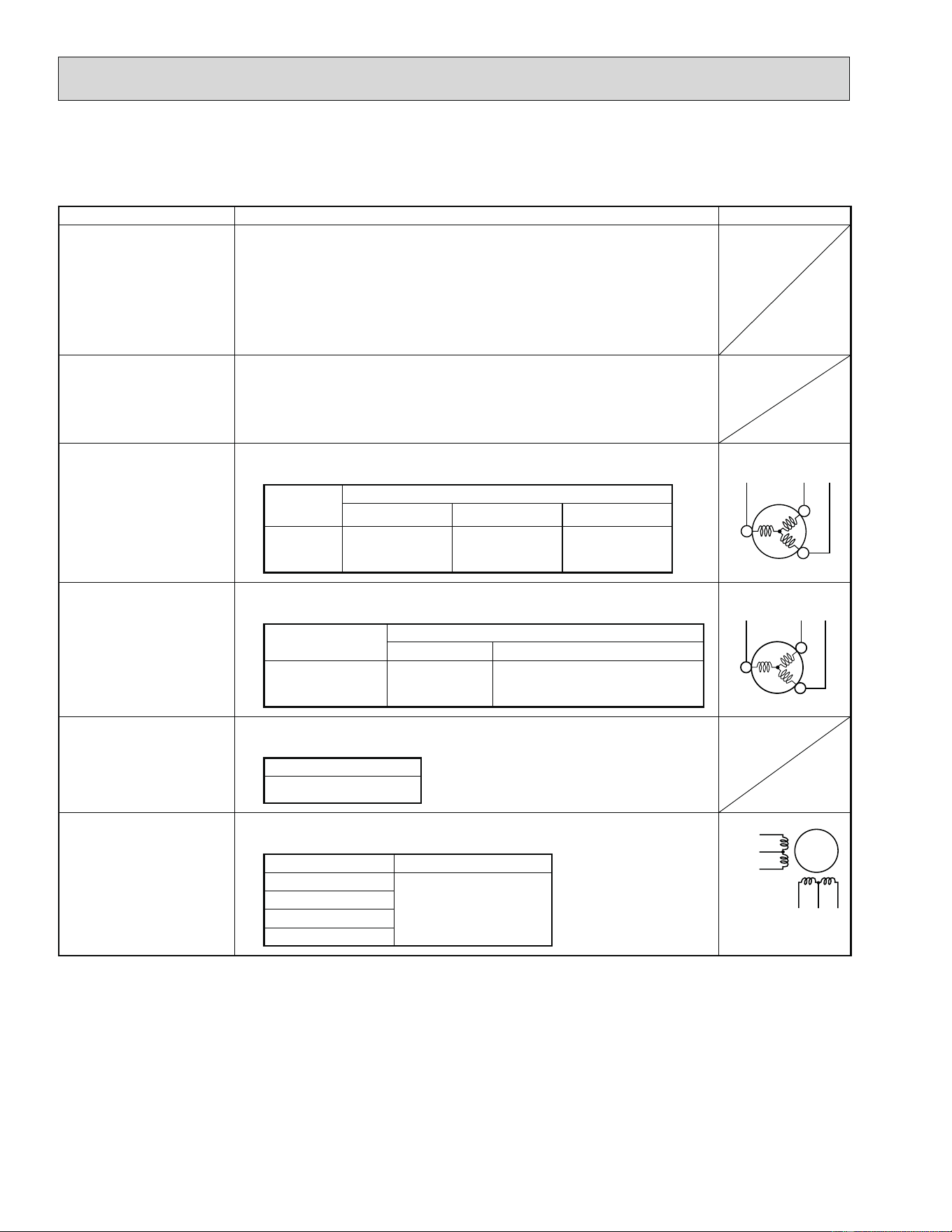
46
10-4. TROUBLE CRITERION OF MAIN PARTS
MUZ-A09NA MUZ-A12NA MUZ-A15NA MUZ-A17NA MUZ-A24NA
MUY-A15NA MUY-A17NA MUY-A24NA MUZ-GA24NA MUY-GA24NA
Part name Check method and criterion Figure
Defrost thermistor (RT61)
(MUZ)
Fin temperature thermistor
(RT64)
Ambient temperature ther-
mistor (RT65)
Outdoor heat exchanger
temperature thermistor
(RT68)
Measure the resistance with a tester.
Refer to 10-6. "Test point diagram and voltage", 1. "Inverter P.C. board" and
3.
"Outdoor electronic
control P.C. board”, for the chart of thermistor.
Discharge temperature
thermistor (RT62)
Measure the resistance with a tester.
Before measurement, hold the thermistor with your hands to warm it up.
Refer to 10-6. "Test point diagram and voltage", 1. "Inverter P.C. board" and
3.
"Outdoor electronic
control P.C. board", for the chart of thermistor.
Compressor (MC)
Measure the resistance between the terminals with a tester.
(Temperature 14 - 104°F)
Normal
A09/12 A15/17/24 GA24
U-V
U-W
V-W
0.43 - 0.53 0.39 - 0.49 0.86 - 1.06
Outdoor fan motor (MF)
Measure the resistance between the terminals with a tester.
(Temperature 14 - 104°F)
Color of lead wire
Normal
A09/12/15/17 A24 GA24
WHT – BLK
BLK – RED
RED – WHT
31 - 41 13 - 16
R. V. coil (21S4)
(MUZ)
Measure the resistance between the terminals with a tester.
(Temperature 14 - 104°F)
Normal
1.20 - 1.55 k
Expansion valve coil (LEV)
Measure the resistance with a tester.
(Temperature: 14 - 104°F)
Color of lead wire Normal
WHT – RED
38 - 50
RED – ORN
YLW – BRN
BRN – BLU
W
U
V
WHT
RED BLK
W
U
V
WHT
RED BLK
LEV
WHT
RED
ORN
YLW
BRN
BLU
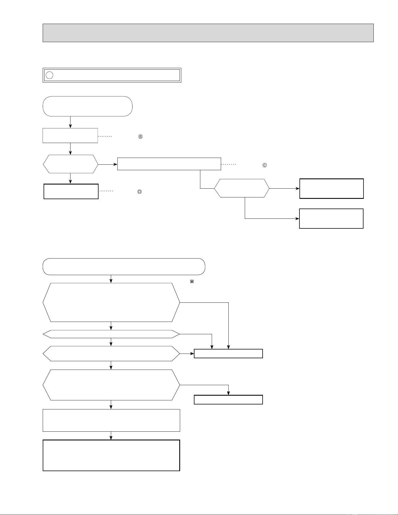
47
10-5. Troubleshooting flow
MUZ-A09/12/15/17 MUY-A15/17
MUZ-A24 MUY-A24 MUZ-GA24 MUY-GA24
Check the voltage
between terminals.
Check the compres-
sor.
Disconnect the connector (CN61)
between compressor and the intel-
ligent power module (IPM).
Check the resistance of the intelligent
power module.
See 10-5. “Check of compressor” .
No
See 10-5. “Check of open phase” .
See 10-5. “Check of intelligent power module”.
Is the resistance
infinite?
Yes
Replace the inverter P.C.
board.
No
(0 - several )
Yes
Is the voltage
balanced?
Replace the inverter P.C.
board and compressor.
Measure the voltage between each lead wire lead-
ing to the compressor.
U (BLK) - V (WHT)
V (WHT) - W (RED)
W (RED) - U (BLK)
Is voltage output on right table?
Yes
No
Disconnect the terminal of the compressor. 3 minutes after turning
on the power supply, start EMERGENCY OPERATION.
After the outdoor fan starts running, wait for 1 minute or more before measur-
ing the voltage.
Output voltage is 50 - 130 V. (The voltage may differ according to the tester.)
Is output balanced?
Yes
No
Is the input voltage to the outdoor electronic control
P.C. board 370 V or more?
Yes
No
Replace the power board.
Turn off power supply of indoor and outdoor unit, and
measure the compressor winding resistance between
the compressor terminals.
Is the resistance between each terminal normal?
Yes
No
Replace the compressor.
Reconnect the lead wire of compressor, and turn on power
supply to indoor and outdoor unit.
3 minutes later, starts EMERGENCY OPERATION.
Clarify the causes by counting time until the inverter stops.
0 to 10 seconds: compressor layer short
10 to 60 seconds: compressor lock
60 seconds to 5 minutes: refrigerant circuit defective
5 minutes or more: normal
A How to check inverter/compressor
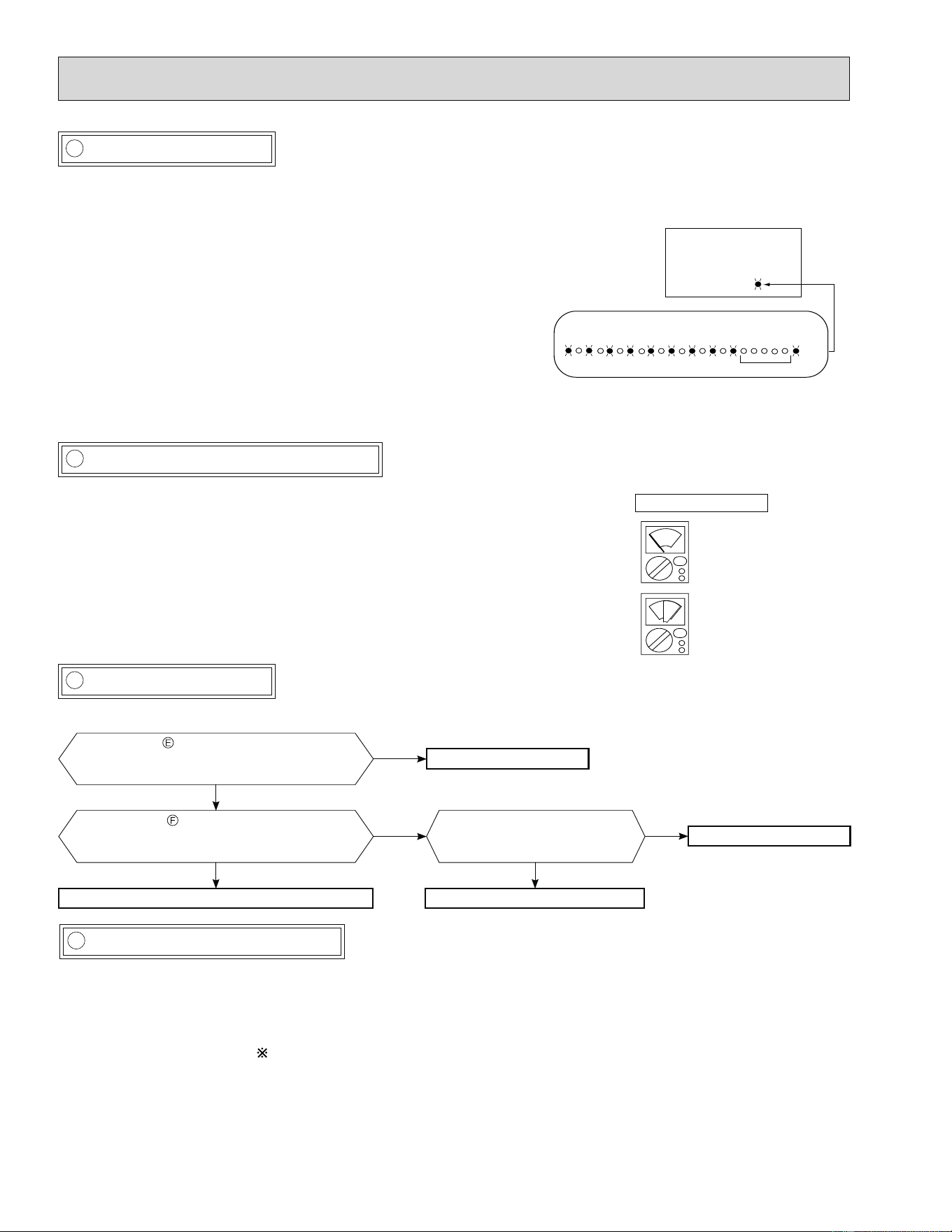
48
Ɣ Disconnect the connector (CN61) between the compressor and intelligent power module, and measure the resistance be-
tween the compressor terminals.
<<Measurement point>>
At 3 points
BLK-WHT
BLK-RED
WHT-RED
<<Judgement>>
Refer to 10-4.
0 [] ················Abnormal (short)
Infinite [] ·······Abnormal (open)
NOTE: 1. Be sure to zero the ohmmeter before measurement.
2. Winding resistance for each phase at 68°F (20°C).
Refer to "3. SPECIFICATION".
Measure the resistance between the lead wires at 3 points.
B Check of open phase
MUZ-A09/12/15/17 MUY-A15/17
MUZ-A09/12/15/17 MUY-A15/17
MUZ-A09/12/15/17 MUY-A15/17
ohmmeter indication
••••••Normal
(infinite)
••••••Abnormal
(0~dozens of )
X1
X1
D Check of compressor
C Check of intelligent power module
MUZ-A09/12/15/17 MUY-A15/17
E Check of compressor winding
Ɣ With the connector between the compressor and the intelligent power module disconnected, activate the inverter and check if
the inverter is normal by measuring the balance of voltage between the terminals.
Output voltage is 50 - 130 V. (The voltage may differ according to the tester.)
<< Operation method>>
Start cooling or heating operation by pressing EMERGENCY OPERATION
switch on the indoor unit. (TEST RUN OPERATION: Refer to 7-6.)
<<Measurement point>>
at 3 points
BLK (U) - WHT (V)
BLK (U) - RED (W)
WHT(V) - RED (W)
NOTE: 1. Output voltage varies according to power supply voltage.
2. Measure the voltage by analog type tester.
3. During this check, LED of inverter P.C. board À ashes 9 times. (Refer to 10-6.1.)
ƔMeasure the resistance between the terminals on the intelligent power module.
<<Measurement point>>
At 6 points
BLK-WHT, WHT-BLK
BLK-RED, RED-BLK
WHT-RED, RED-WHT
<<Judgement>>
In¿ nite []············Normal
0 - dozens of········Abnormal (short)
Refer to 10-5. “Check of compressor
operation time”.
Does the compressor operate continuously?
OK.
No
Yes
Refer to 10-5. “Check of compressor
winding”.
Is the compressor normal?
Replace the compressor.
No
Yes
Is the compressor operation
time more than 10 seconds?
Check the refrigerant circuit.
Yes
Replace the compressor.
No
LED
Inverter P.C. board
(Parts side)
9-time flash
2.5-second OFF
Flashing
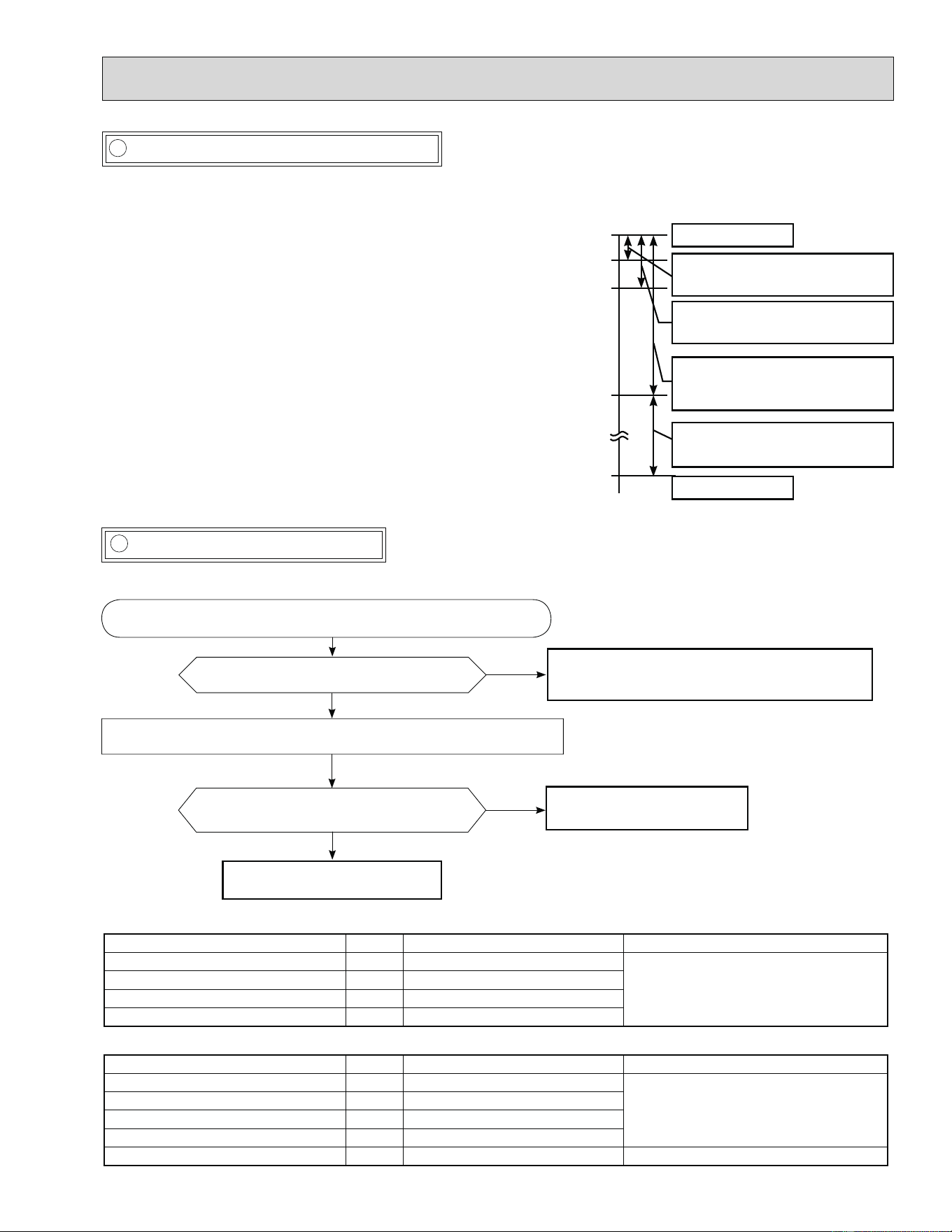
49
F Check of compressor operation time
MUZ-A09/12/15/17 MUY-A15/17
G Check of outdoor thermistors
Ɣ Connect the compressor and activate the inverter. Then measure
the time until the inverter stops due to over current.
<<Operation method>>
Start heating or cooling operation by pressing EMERGENCY
OPERATION switch on the indoor unit.
(TEST RUN OPERATION: Refer to 7-6.)
<<Measurement>>
Measure the time from the start of outdoor fan running to the stop
of compressor due to overcurrent.
MUZ-A09/12/15/17 MUY-A15/17
Thermistor Symbol Connector, Pin No. Board
Defrost RT61 Between CN641 pin 1 and pin 2
Inverter P.C. board
Discharge temperature RT62 Between CN641 pin 3 and pin 4
Fin temperature RT64 Between CN642 pin 1 and pin 2
Ambient temperature RT65 Between CN643 pin 1 and pin 2
MUZ-A24 MUY-A24 MUZ-GA24 MUY-GA24
Thermistor Symbol Connector, Pin No. Board
Defrost RT61 Between CN661 pin 1 and pin 2
Outdoor electronic control P.C. board
Discharge temperature RT62 Between CN661 pin 3 and pin 4
Outdoor heat exchanger temperature RT68 Between CN661 pin 7 and pin 8
Ambient temperature RT65 Between CN663 pin 1 and pin 2
Fin temperature RT64 Between CN3 pin 1 and pin 2 Outdoor power board
Replace the thermistor except RT64.
When RT64 is abnormal, replace the inverter P.C.
board or the outdoor power board.
Replace the inverter P.C. board
or the outdoor power board.
No
No
Is the thermistor normal? (Refer to 10-6.1.
or 10-6.3.)
Reconnect the connector of thermistor.
Turn ON the power supply and press EMERGENCY OPERATION switch.
Does the unit operate for 10 minutes or more
without showing thermistor abnormality?
OK.
(Cause is poor contact.)
Yes
Yes
Disconnect the connector of thermistor in the outdoor P.C. board (see
below table), and measure the resistance of thermistor.
Compressor starts
Abnormal
(IPM failure)
(Compressor winding short)
Abnormal
(Compressor lock out)
(Starting defect)
Abnormal
(Poor contact,)
(Outdoor P.C. board defect)
(Disconnected connector)
Abnormal
(Refrigerant circuit defect)
(Closed valve)
Normal
0 second
1 second
2 seconds
10 seconds
10 minutes
<<Judgement>>
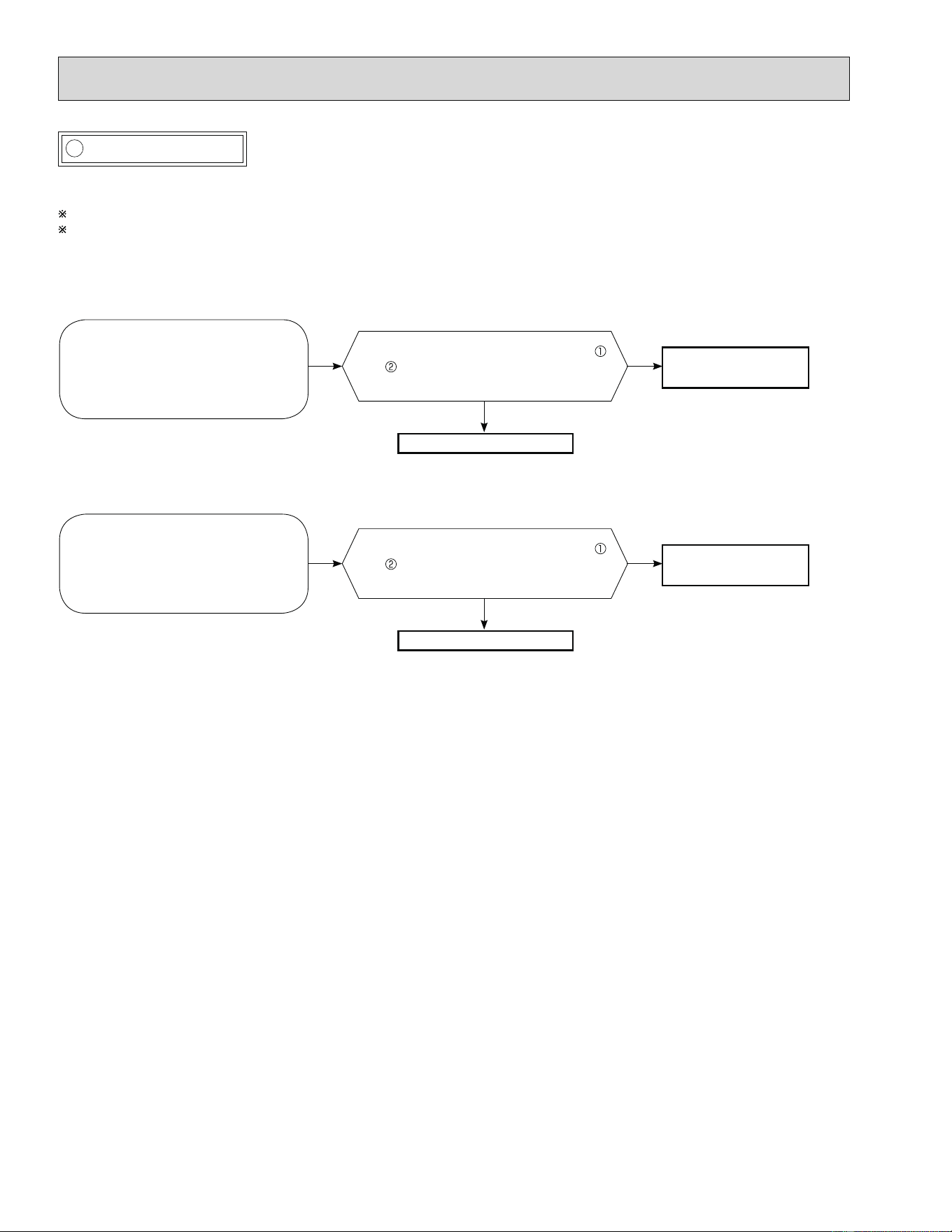
50
Disconnect connector (CN61)
between the compressor and the
intelligent power module.
Turn ON the power supply and press
EMERGENCY OPERATION switch
twice (HEAT mode).
H Check of R.V. coil
MUZ-A09/12/15/17
First of all, measure the resistance of R.V. coil to check if the coil is defective. Refer to 10-4.
In case CN721 is disconnected or R.V. coil is open, voltage is generated between the terminal pins of the connector
although no signal is being transmitted to R.V. coil.
Check if CN721 is connected.
Is there 208/230 VAC between CN721
and on the power P.C. board 3 minutes
after the power supply is turned ON?
No
Yes
Replace the 4-way valve.
Unit operates COOL mode even if it is set to HEAT mode.
Is there 208/230 VAC between CN721
and on the power P.C. board 3 minutes
after the power supply is turned ON?
Yes
No
Replace the 4-way valve.
Unit operates HEAT mode even if it is set to COOL mode.
Disconnect connector (CN61)
between the compressor and the
intelligent power module.
Turn ON the power supply and
press EMERGENCY OPERATION
switch once (COOL mode).
Replace the power
P.C. board.
Replace the power
P.C. board.
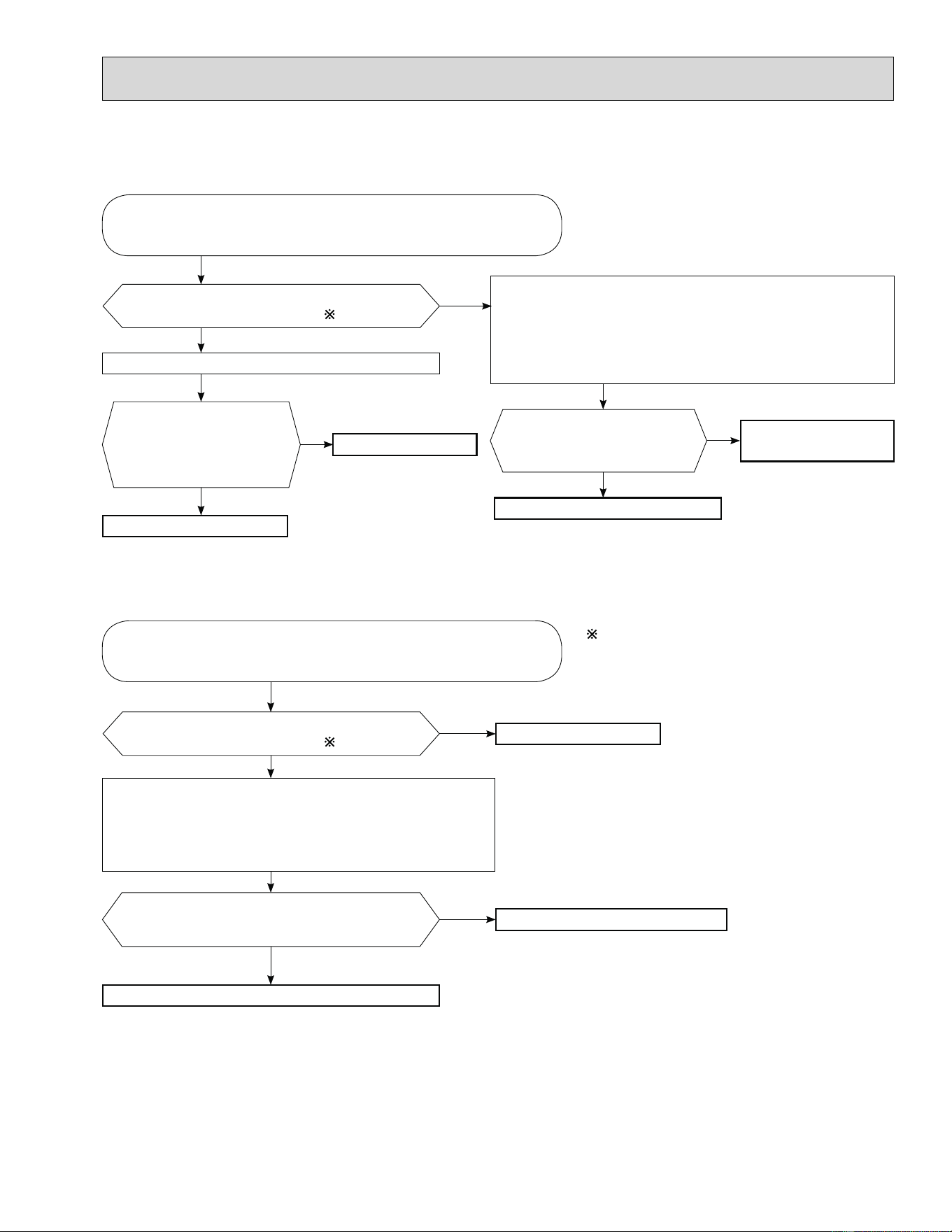
51
MUZ-A24 MUZ-GA24
Heating operation does not work.•
Is there voltage of 208/230 VAC between pin1
and pin 2 at connector CN912?
Yes
No
Disconnect the lead wire leading to the compressor.
3 minutes after turning on the power supply, start EMERGENCY
OPERATION in HEAT mode.
1.
2.
Turn off power supply of indoor and outdoor unit, and discon-
nect the connector CN781 in the outdoor electronic control P.C.
board.
3 minutes after turning ON the power supply, start EMER-
GENCY OPERATION in HEAT mode.
1.
2
.
Turn OFF power supply of indoor and outdoor unit.
Is there voltage 12 VDC be-
tween the connector CN781
pin 5 (+) and pin 3 (-)?
No
Disconnect the connec-
tor CN912 in noise ¿ lter
P.C. board. Is there normal
resistance to R.V. coil?
No
Replace the R.V. coil.
Replace the 4-way valve.
Replace the noise ¿ lter P.C. board.
Yes
Replace the electronic
control P.C. board.
Cooling operation does not work.
•
Is there voltage of 208/230 VAC between pin1
and pin 2 at connector CN912?
Disconnect the lead wire leading to the compressor.
3 minutes after turning on the power supply, start EMERGENCY
OPERATION in COOL mode.
1.
2
.
Turn OFF power supply of indoor and outdoor unit, and
disconnect the connector CN781 in the outdoor electronic
control P.C. board.
3 minutes after turning ON the power supply, start EMER-
GENCY OPERATION in COOL mode.
1.
2.
Yes
Is there voltage 12 VDC between the connector
CN781 pin 5 (+) and pin 3 (-)?
No
Replace the noise ¿ lter P.C. board.
Replace the outdoor electronic control P.C. board.
No
Replace the 4-way valve.
If the connector CN912 is disconnected or R.V.
coil is open, voltage occurs between terminals
even when the control is OFF.
Yes
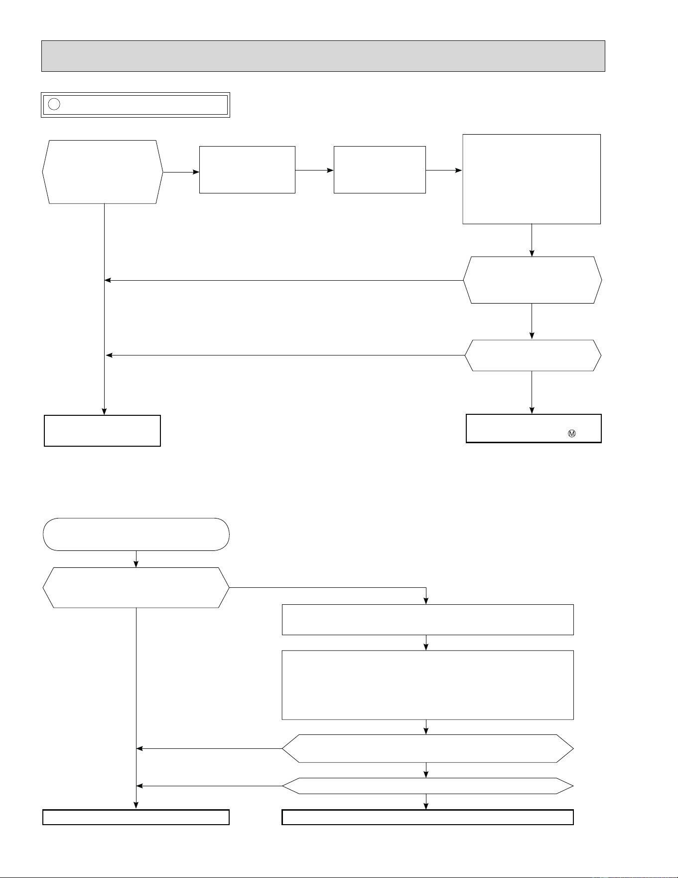
52
MUZ-A09/12/15/17 MUY-A15/17
I Check of outdoor fan motor
MUZ-A24 MUY-A24 MUZ-GA24 MUY-GA24
Is the resistance
between each terminal
of outdoor fan motor
normal?
(Refer to 10-4.)
No
Yes
Disconnect CN932
from the inverter
P.C. board.
Turn ON the power
supply.
Rotate the outdoor fan
slowly by hand, and measure
the voltage of CN931
(Measurement of feedback
output).
Between 1(+) and 5(-)
Between 2(+) and 5(-)
Between 3(+) and 5(-)
Does the voltage between
each terminal repeat 5
and 0 VDC by turns?
Does the outdoor fan
rotate smoothly?
Check the inverter P.C.
board. (Refer to 10-5. )
Replace the outdoor fan
motor.
(Fixed to either 5 or 0 VDC) No
No
Is the resistance between each ter-
minal of outdoor fan motor normal?
(Refer to 10-4.)
Check the connection between the
connector CN931 and CN932.
Disconnect CN932 from outdoor electronic control P.C. board,
and turn on the power supply.
Rotate the outdoor fan motor manually and measure the voltage
of CN931.
Between 1(+) and 5(-)
Between 2(+) and 5(-)
Between 3(+) and 5(-)
Does the voltage between each terminal become 5 and 0
VDC repeatedly?
Does the outdoor fan motor rotate smoothly?
Replace the outdoor fan motor. Replace the outdoor electronic control P.C. board.
Yes
Yes
No
(Fixed to either 5 or 0 VDC)
No
No
Yes
Yes
Yes
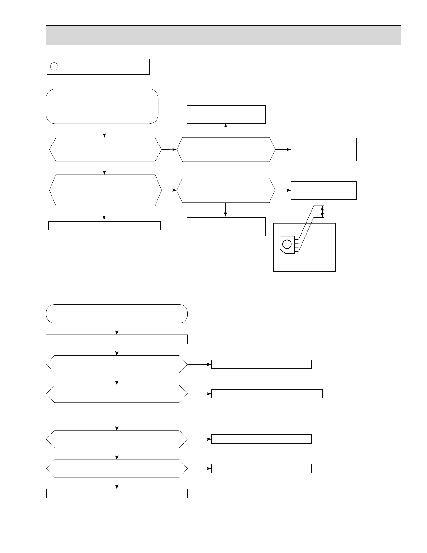
53
MUZ-A24 MUY-A24 MUZ-GA24 MUY-GA24
MUZ-A09/12/15/17 MUY-A15/17
J Check of power supply
Is there voltage 208/230 VAC
between the indoor terminal
block S1 and S2?
No
Yes
Replace the indoor
electronic control P.C.
board.
Rectify indoor/outdoor
connecting wire.
Yes
If light up, OK.
If À ash, refer to 10-3.
Does the left lamp of OPERATION
INDICATOR lamp on the indoor unit
light up?
Does LED on the inverter P.C.
board light up or À ash? (Refer
to 10-6.1.)
No
Replace the inverter
P.C. board.
Is there voltage 260 - 300 VDC
between DB61 (+) and DB61 (–) on
the inverter P.C. board?
(Refer to 10-6.1.)
No
Check the electric parts in main circuit.
Yes
Yes
No
Disconnect the connector (CN61)
between compressor and intelligent
power module.
Turn ON power supply and press
EMERGENCY OPERATION switch.
Inverter P.C. board
(Solder side)
DB61
260 - 300 VDC
Is there voltage of 208/230 VAC in the power
supply terminal block?
Check the connecting of parts of main power
supply circuit.
Check the power supply cable.
Turn ON power supply.
Is the output voltage from the noise ¿ lter P.C.
board 208/230 VAC?
Replace the noise ¿ lter P.C. board.
No
Yes
No
Yes
Is the input voltage to the power board
208/230 VAC?
Replace the reactor.
No
Yes
Is the input voltage to the outdoor electronic
control P.C. board 294/325 VDC?
Replace the power board.
No
Replace the outdoor electronic control P.C. board.
Yes
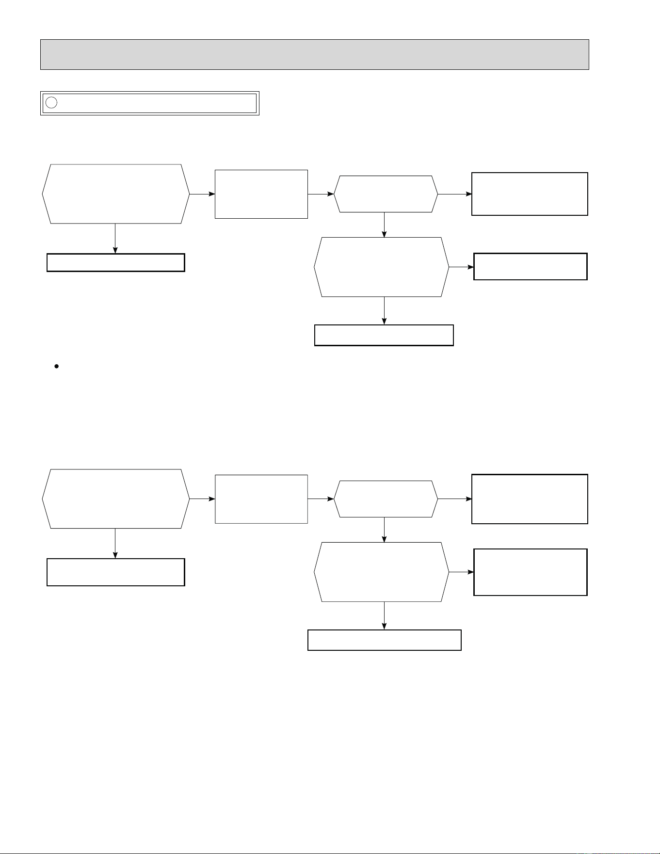
54
MUZ-A09/12/15/17 MUY-A15/17
K Check of current-limiting resistor
MUZ-A24 MUY-A24 MUZ-GA24 MUY-GA24
When the current-limiting resistor is open, the rush current limiting relay (X64) may not work properly.
Replace the power P.C.
board or the inverter P.C.
board.
Does LED on the
inverter P.C. board
light up?
Does the rush current
limiting relay (X64) work
properly? (Normally it
closes 1 second after
outdoor unit power ON.)
Is the resistance of current-
limiting resistor (R64A or
R64B) on the power P.C.
board normal?
(Normal resistance: 5 ±5%)
No
Check other electric parts in the main circuit together in the case that the current-limiting resistor is defective.
Yes
Turn ON the power
supply and press
EMERGENCY
OPERATION switch.
Replace the inverter P.C.
board or the compressor.
Replace the power P.C. board.
Replace the power P.C. board.
Yes
Yes
No
No
When the current-limiting resistor is open, the rush current limiting relay (X64) may not work properly.
Replace the noise ¿ lter
P.C. board or the outdoor
electronic control P.C.
board.
Does LED on the
outdoor electronic
P.C. board light up?
Does the rush current
limiting relay (X64) work
properly? (Normally it
closes 1 second after
outdoor unit power ON.)
Is the resistance of current-
limiting resistor (R64A or
R64B) on the noise ¿ lter P.C.
board normal?
(Normal resistance: 5 ±5%)
No
Ɣ Check other electric parts in the main circuit together in the case that the current-limiting resistor is defective.
Yes
Turn ON the power
supply and press
EMERGENCY
OPERATION switch.
Replace the outdoor
electronic control P.C.
board or power P.C.
board or the compressor.
Replace the noise ¿ lter P.C.
board.
Replace the noise ¿ lter P.C. board.
Yes
Yes
No
No
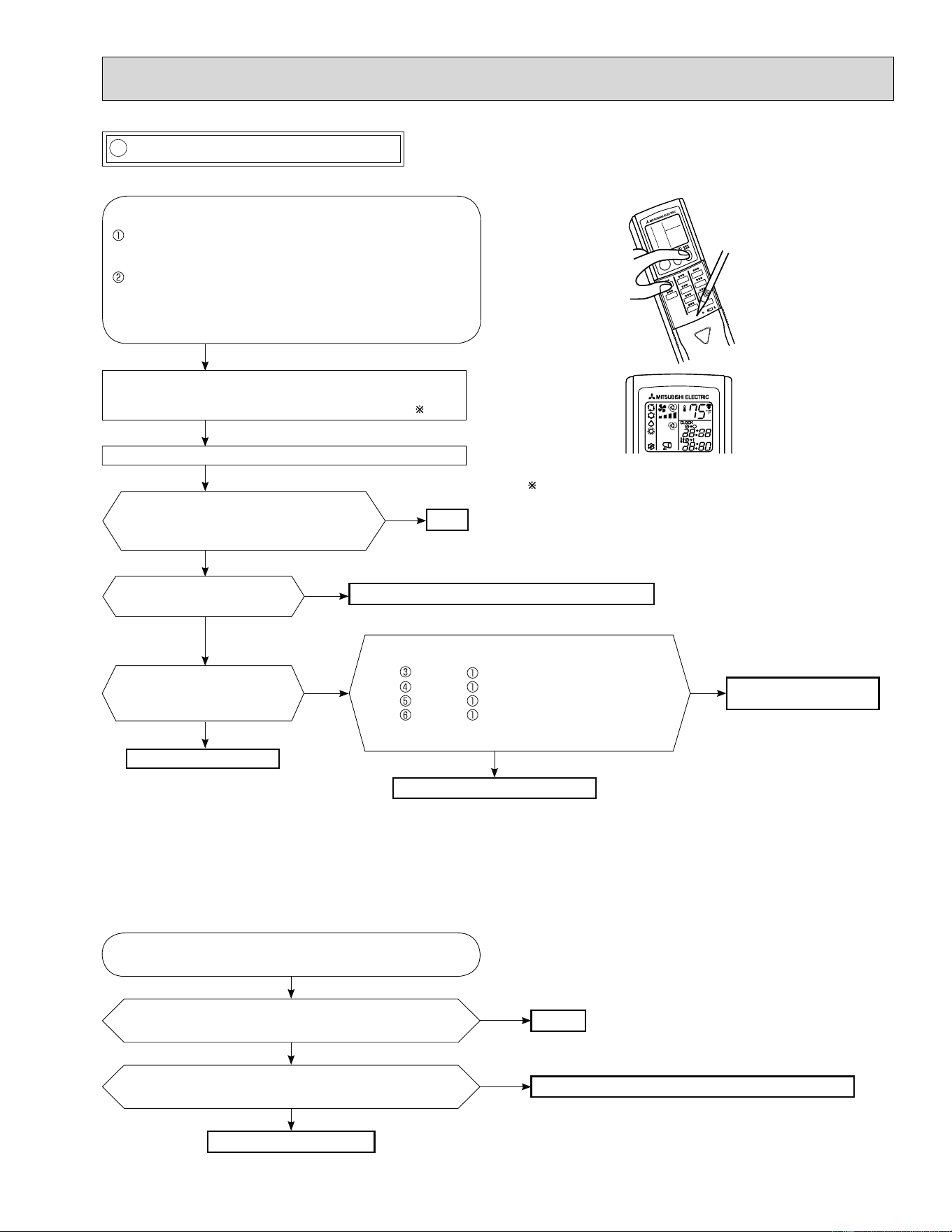
55
MUZ-A09/12/15/17 MUY-A15/17
L Check of LEV (Expansion valve)
This figures show about MSZ-A09/12/15/17.
MUZ-A24 MUY-A24 MUZ-GA24 MUY-GA24
Press OPERATE/STOP (ON/OFF) button of the remote
controller (the set temperature is displayed) with the
remote controller headed towards the indoor unit.
1
Expansion valve operates in full-opening direction.
OK
NOTE: After check of LEV, do the undermentioned operations.
1. Turn OFF the power supply and turn ON again.
2. Press RESET button on the remote controller.
1. Regardless of normal or abnormal condition, a
short beep is emitted once the signal is received.
Measure each voltage between connector pins of
CN724 on the inverter P.C. board.
1. Pin (-) — Pin (+)
2. Pin (-) — Pin
(+)
3. Pin
(-) — Pin (+)
4. Pin (-) — Pin (+)
Is there about 3 - 5 VAC between each?
NOTE: Measure the voltage with an analog tester.
Properly ¿ x the LEV coil to the expansion valve.
Replace the inverter
P.C. board.
Replace the LEV coil.
Replace the expansion valve.
Is LEV coil properly ¿ xed to
the expansion valve?
Does the resistance of LEV
coil have the characteristics?
(Refer to 10-4.)
Do you hear the expansion valve "click,
click·······"?
Do you feel the expansion valve vibrate
on touching it ?
Turn ON the power supply.
<Preparation of the remote controller>
While pressing both OPERATION SELECT button and
TOO COOL button on the remote controller at the same
time, press RESET button.
First, release RESET button.
Hold down the other two buttons for another 3 seconds.
Con¿ rm that the indicators on the LCD screen shown in
the right ¿ gures are all displayed.
Then release the buttons.
Yes
No
No
Yes
No
Yes
No
Yes
Turn ON power supply to the outdoor unit after checking
LEV coil is mounted to the LEV body securely.
Is "click - click" sound heard?
Or, do you feel vibration of the LEV coil with a hand?
Disconnect the connector CN795.
Is there normal resistance to LEV coil?
Normal
Replace the outdoor electronic control P.C. board.
Replace the LEV coil.
Yes
No
No
Yes
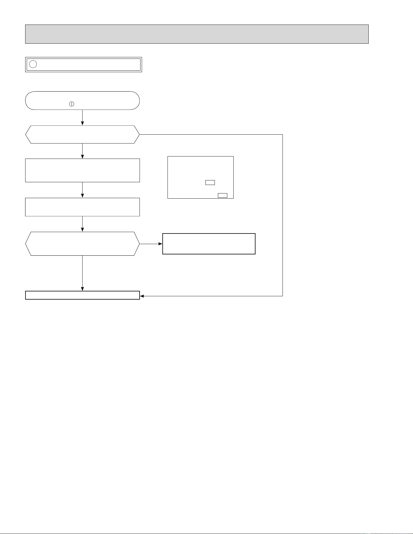
56
M Check of inverter P.C. board
MUZ-A09/12/15/17 MUY-A15/17
Check the outdoor fan motor.
(Refer to 10-5. .)
Is the fuse (F901) blown on the in-
verter P.C. board?
Check the connection of the connectors.
(CN931, CN932) of outdoor fan motor.
If the connection is poor, correct it.
Operate the outdoor unit by starting
EMERGENCY OPERATION.
Check the LED indication on the in-
verter P.C. board.
Does the LED À ash 10-time?
Replace the inverter P.C. board.
Check the corresponding parts
following LED indication.
(Refer to 10-3.)
Yes
No
Yes
(10-time À ash)
No
Inverter P.C. board
(Solder side)
CN932
CN931
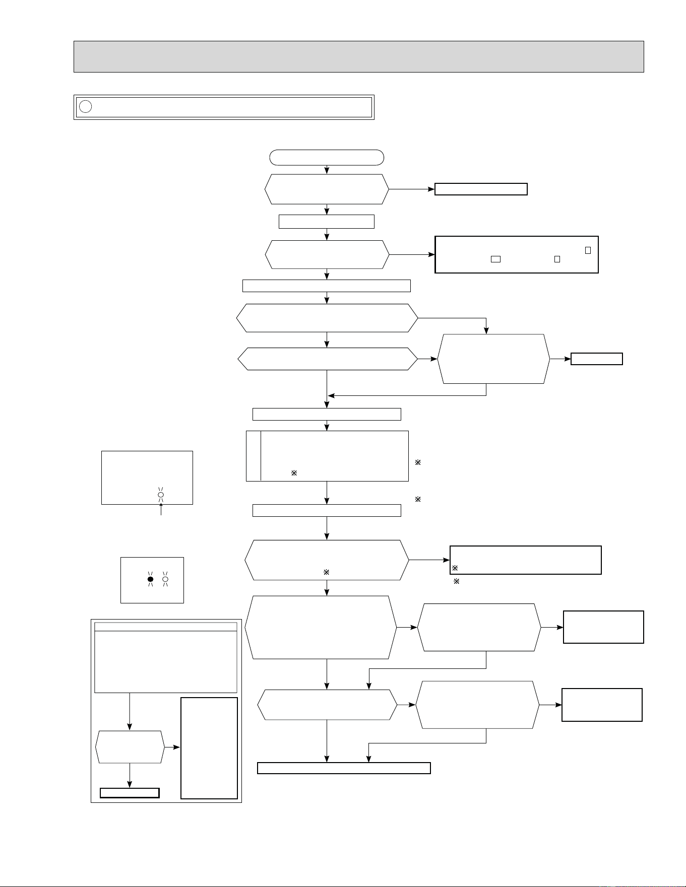
57
N How to check miswiring and serial signal error
Inverter P.C.board
(Parts side)
LED
Blinking
Outdoor electronic control P.C. board
BlinkingLighted
(Parts side)
LED2
LED1
Turn OFF the power supply.
Is there rated voltage in the
power supply?
Yes
No
Turn ON the power supply.
Check the power supply.
Is there rated voltage between
outdoor terminal block S1 and
S2?
No
• Check the wiring.
• Check the fuse (F65). (For MUZ-A24NA-
1
,
MUZ-A24NA-
U2
,
MUY-A24NA-
1
,
MUZ-
GA24
,
MUY-GA24
.
)
Press EMERGENCY OPERATION switch once.
Does the left lamp of OPERATION INDICA-
TOR lamp light up? <Con¿ rmation of the
power to the indoor unit>
Yes
No
Is serial signal error indicated 6 minutes later?
Yes
No
Is there any miswiring, poor
contact, or wire disconnec-
tion of the indoor/outdoor
connecting wire?
Yes
Correct them.
No
A
Turn OFF the power supply.
Check once more if the indoor/outdoor
connecting wire is not miswiring.
Short-circuit outdoor terminal block S2
and S3.
1
B
1. Miswiring may damage indoor electronic control P.C.
board during the operation.
Be sure to con¿ rm the wiring is correct before the opera-
tion starts.
3. Be sure to check this within 3 minutes after turning ON.
After 3 minutes, LED blinks 6 times. Even when the
inverter P.C. board or the outdoor electronic control P.C.
board is normal, LED blinks 6 times after 3 minutes.
Turn ON the power supply.
Does the LED on the inverter P.C. board or
the outdoor electronic control P.C. board
repeat "3.6-second-OFF and 0.8-second-
ON quick blinking"? 3
Yes
No
(Lighted
or not
lighted)
Replace the inverter P.C. board or
the outdoor electronic control P.C. board.
2
2. Be careful of the residual voltage
of smoothing capacitor.
Turn OFF the power supply.
Remove the short-circuit between
outdoor terminal block S2 and S3.
Turn ON the power supply.
Is there amplitude of 10 to 20 VDC
between outdoor terminal block S2 and
S3? <Con¿ rmation of serial signal>
Yes
No
Is there any error of the in-
door/outdoor connecting wire,
such as the damage of the wire,
intermediate connection, poor
contact to the terminal block?
Yes
Replace the indoor/
outdoor connecting
wire.
Turn OFF inverter-controlled lighting
equipment.
Turn OFF the power supply and then
turn ON again.
Press EMERGENCY OPERATION
switch.
•
•
•
A
Is serial signal
error indicated 6
minutes later?
B
Yes
Reinstall
either the unit
or the light
away from
each other.
Attach a ¿ lter
on remote
control
receiving
section of the
indoor unit.
•
•
No
Is there rated voltage between
indoor terminal block S1 and S2?
<Con¿ rmation of power voltage>
No
No
Is there any error of the in-
door/outdoor connecting wire,
such as the damage of the wire,
intermediate connection, poor
contact to the terminal block?
Yes
Replace the indoor/
outdoor connecting
wire.
No
Replace the indoor electronic control P.C. board.
Yes
Be sure to release the failure-mode recall function
after checking.
Yes
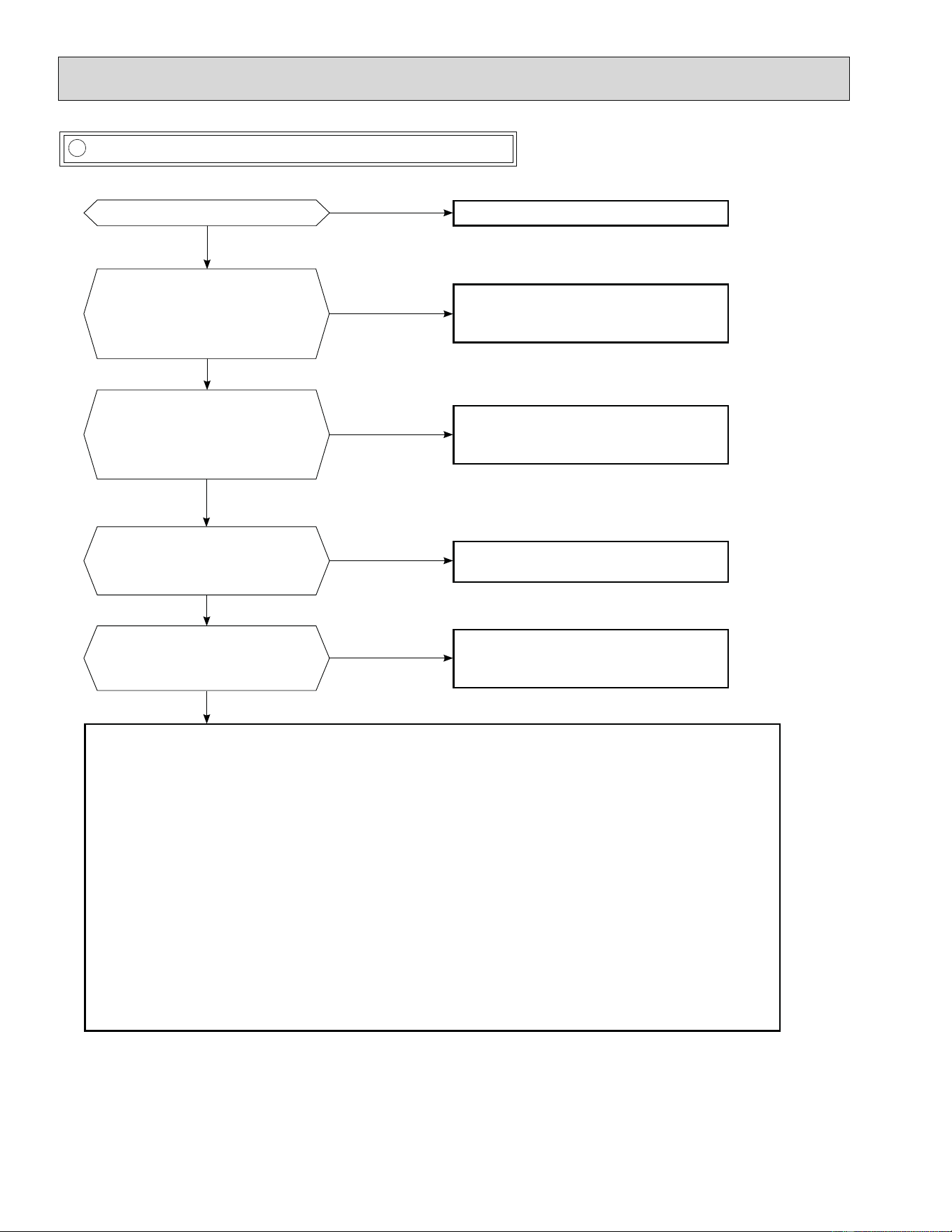
58
O Electromagnetic noise enters into TV sets or radios
Yes
Is the unit grounded?
No
Ground the unit.
Yes
Is the distance between the antennas
and the indoor unit within 9.91 ft., or is
the distance between the antennas and
the outdoor unit within 9.91 ft.?
No
Extend the distance between the antennas and
the indoor unit, and/or the antennas and the
outdoor unit.
Is the distance between the TV sets or
radios and the indoor unit within 3.28
ft., or is the distance between the TV
sets or radios and the outdoor unit
within 9.91 ft.?
Yes
Extend the distance between the TV sets and/or
radios and the indoor unit, or the TV sets or
radios and the outdoor unit.
Are the antennas damaged?
Is the coaxial cable damaged?
Is there any poor contact in the anten-
na wiring?
Yes
No
No
Replace or repair the antenna.
Replace or repair the coaxial cable.
Is the indoor/outdoor connecting wire of
the air conditioner and the wiring of the
antennas close?
Yes
Extend the distance between the indoor/outdoor
connecting wire of the air conditioner and the wir-
ing of the antennas.
No
Even if all of the above conditions are ful¿ lled, the electromagnetic noise may enter, depending on the electric ¿ eld strength
or the installation condition (combination of speci¿ c conditions such as antennas or wiring).
Check the followings before asking for service.
1. Devices affected by the electromagnetic noise
TV sets, radios (FM/AM broadcast, shortwave)
2. Channel, frequency, broadcast station affected by the electromagnetic noise
3. Channel, frequency, broadcast station unaffected by the electromagnetic noise
4. Layout of:
indoor/outdoor unit of the air conditioner, indoor/outdoor wiring, grounding wire, antennas, wiring from antennas, receiver
5. Electric ¿ eld intensity of the broadcast station affected by the electromagnetic noise
6. Presence or absence of ampli¿ er such as booster
7. Operation condition of air conditioner when the electromagnetic noise enters in
1) Turn OFF the power supply once, and then turn ON the power supply. In this situation, check for the electromagnetic
noise.
2) Within 3 minutes after turning ON the power supply, press OPERATE/STOP (ON/OFF) button on the remote controller for
power ON, and check for the electromagnetic noise.
3) After a short time (3 minutes later after turning ON), the outdoor unit starts running. During operation, check for the elec-
tromagnetic noise.
4) Press OPERATE/STOP (ON/OFF) button on the remote controller for power OFF, when the outdoor unit stops but the
indoor/outdoor communication still runs on. In this situation, check for the electromagnetic noise.
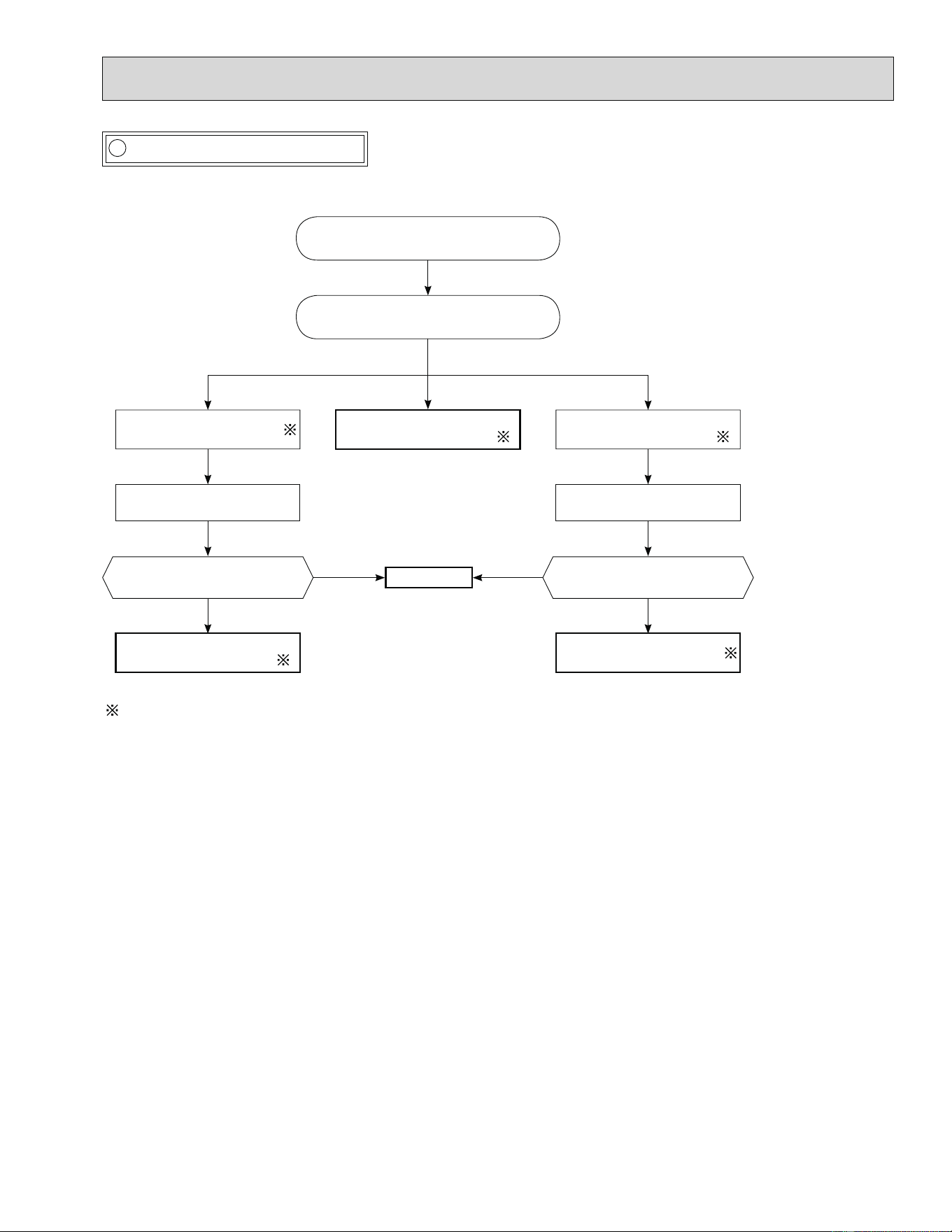
59
P Check of bus-bar voltage
MUZ-A24NA MUY-A24NA MUZ-GA24NA MUY-GA24NA
•Check the voltage of power supply.
•Con¿ rm outdoor unit failure mode
recall function. (Refer to 10-2.2)
Blink 5 times
Con¿ rm LED1 indication lamp on
the outdoor electronic control P.C.
board.
Replace the power board.
Blink 9 times
Replace the outdoor elec-
tronic control P.C. board.
Turn OFF power supply before removing P.C. board.
Con¿ rm LED1 indication lamp
on the outdoor electronic con-
trol P.C. board.
Turn ON power supply.
Start operation.
Blink 6 times
Replace the outdoor elec-
tronic control P.C. board.
Lighting
Replace the outdoor elec-
tronic control P.C. board.
Blink 9 times
Replace the power board.
Con¿ rm LED1 indication lamp
on the outdoor electronic con-
trol P.C. board.
Turn ON power supply.
Start operation.
Normal.
Lighting Lighting
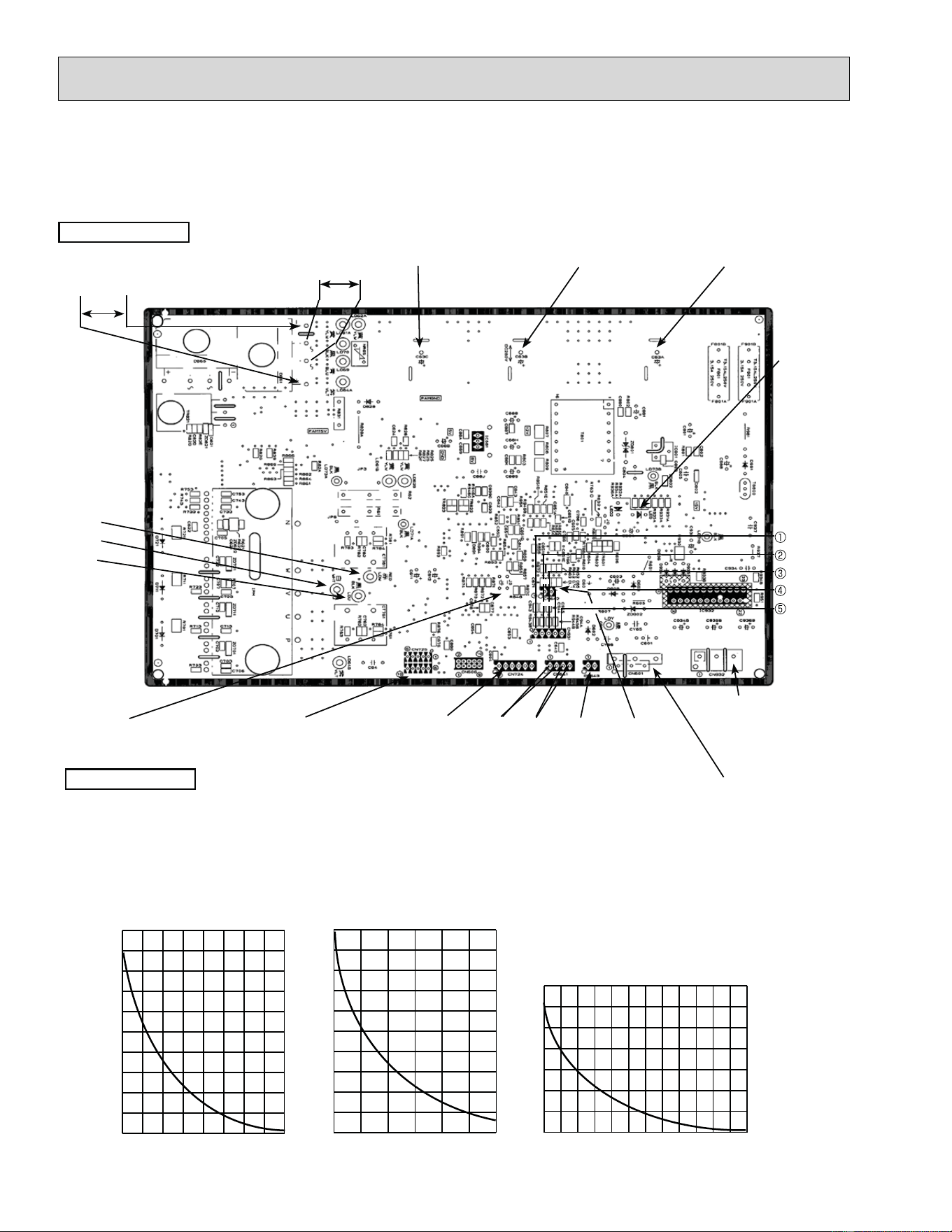
60
Back side of unit
-4 14 32 50 68 86 104
0
10
20
30
40
50
60
70
80
90
100
Temperature (°F)
Ambient temperature thermistor (RT65)
Defrost thermistor (RT61)
Temperature (°F)
Discharge temperature thermistor (RT62)
32 50 68 86 104 122 140 158 176 194 212 230 248
0
100
200
300
400
500
600
700
32 50 68 86 104 122 140 158 176
0
20
40
60
80
100
120
140
160
180
200
Temperature (°F)
Fin temperature thermistor (RT64)
Resistance(k)
Resistance(k)
Resistance(k)
CN932
Output to drive
outdoor fan motor
CN642 Fin temperature
thermistor (RT64)
CN643 Ambient tempera-
ture thermistor (RT65)
CN641 Discharge temper-
ature thermistor (RT62)
CN641 Defrost thermistor
(RT61)
CN724
LEV
connector
DB61
208/230 VAC
CN725
Connecting wire with
power P.C. board
JS
Jumper wire for change
in defrost setting
Front side of unit
DB61
260V - 300 VDC
C63C
Smoothing capacitor
C63A
Smoothing capacitor
C63B
Smoothing capacitor
CN931
Rotational frequency feedback
signal of outdoor fan motor
(+)
(+)
(+)
5V
GND
Output to
drive
compressor
(LDW,
LDV,
LDU)
LED
monitor
lamp
CN601
Connector for indoor/
outdoor communication
(+)
(-)
1. Inverter P.C. board
MUZ-A09NA MUZ-A12NA MUZ-A15NA MUZ-A17NA
MUY-A15NA MUY-A17NA
10-6. TEST POINT DIAGRAM AND VOLTAGE
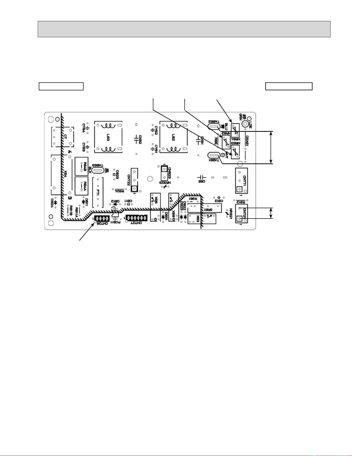
61
MUZ
CN721 R.V.coil
208/230 VAC
Back side of unit
MUZ-A09NA MUZ-A12NA MUZ-A15NA MUZ-A17NA MUY-A15NA MUY-A17NA
Front side of unit
CN726
Connecting wire with
inverter P.C.board
208/230 VAC
NR63
Varistor
NR62
Varistor
NR64
Varistor
2. Power P.C. board
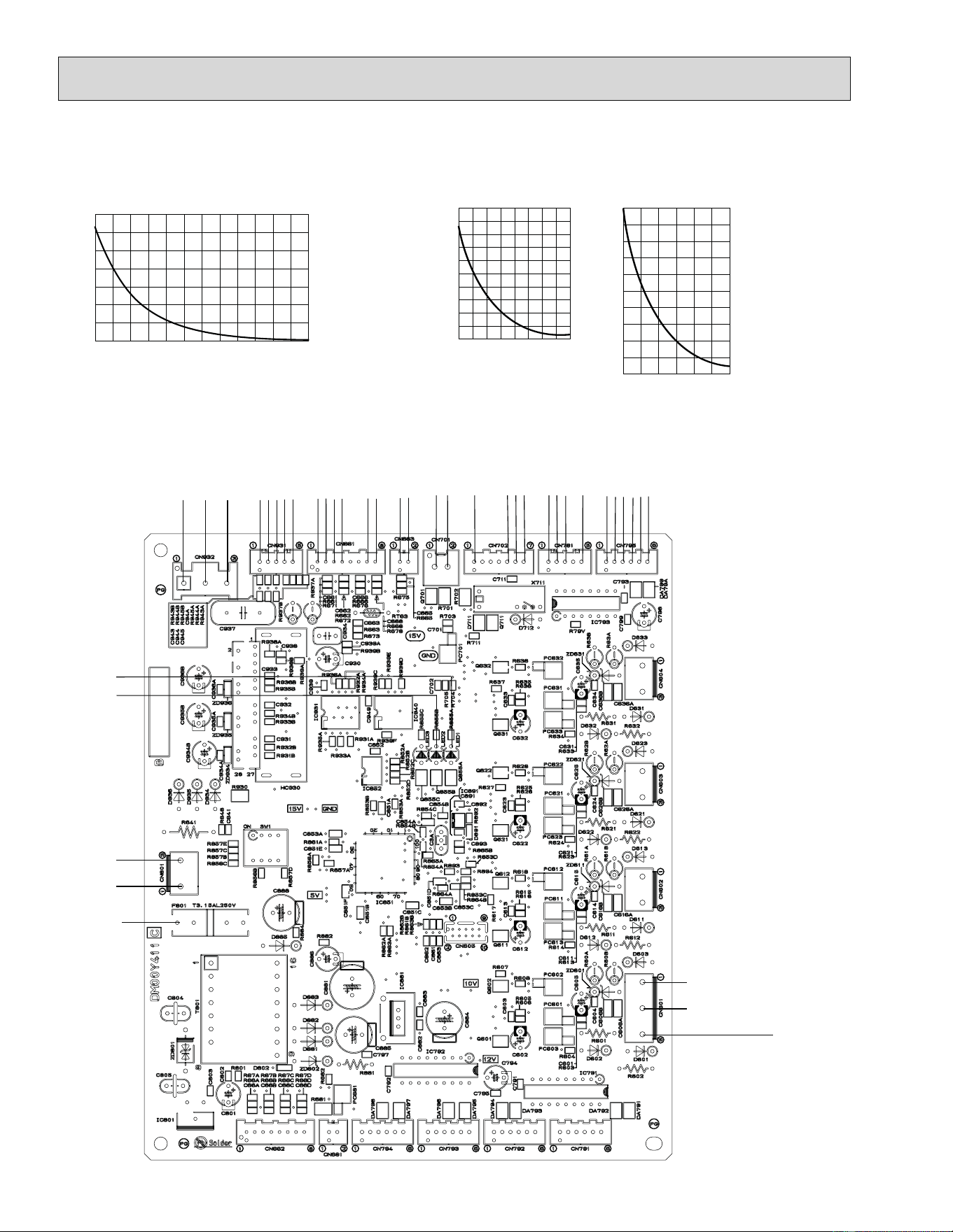
62
-4 14 32 50 68 86 104
100
90
80
70
60
50
40
30
20
10
0
32 50 68 86 104 122 140 158 176
200
180
160
140
120
100
80
60
40
20
0
Resistance (k)
Resistance (k)
Temperature (°F)
Temperature (°F)
Defrost thermistor (RT61)
Ambient temperature thermistor (RT65)
Outdoor heat exchanger temperature thermistor (RT68)
Fin temperature thermistor (RT64)
3. Outdoor electronic control P.C. board
MUZ-A24NA MUY-A24NA MUZ-GA24NA MUY-GA24NA
LED 1
LED 2
Bus-bar
voltage
CN801
294 - 370
VDC
Input
(
(
CN932
20-90 VAC
GND
5V
5 VDC
pulse wave
(
To fan
motor
Defrost thermistor
(RT61)(MUZ)
Discharge temperature
thermistor(RT62)
Outdoor heat exchanger
temperature thermistor (RT68)
(
(
(+)
(–)
(+)
Rush current relay
(–)
R.V. coil (–)
(
12V
DC
15V
15V
CN931
(+)
(–)
(
CN661
CN701
Signal transmission
(To power board)
5 VDC pulse wave
(+)
(–)
(
GND
CN702
Signal reception
(From power board)
5 VDC pulse wave
GND (power board)
CN781
CN795
12 VDC
pulse wave
LEV
(
(
(
(
32 50 68 86 104 122 140 158 176 194 212 230 248
700
600
500
400
300
200
100
0
Resistance (k)
Temperature (°F)
Discharge temperature thermistor (RT62)
F801
FUSE
T3.15AL250V
(
Ambient temperature
thermistor (RT65)
CN663
for indoor
5-10 VDC
CN601
208/230 VAC
60 Hz
Input
(
(
(
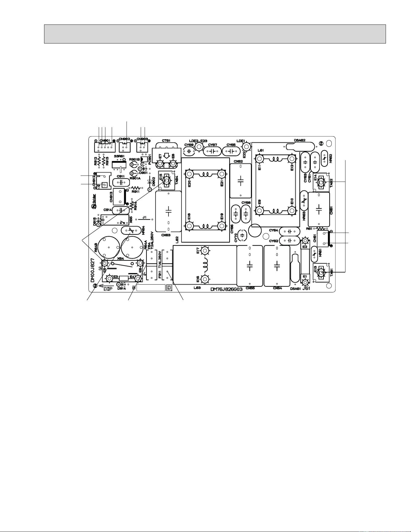
63
{
MUZ
CN912
R.V. coil
208/230 VAC
60Hz
Output
208/230 VAC
60Hz
Input
208/230 VAC
60Hz
Output
{
CN901
To electronic
control
P.C. board
MUZ-A24NA MUY-A24NA MUZ-GA24NA MUY-GA24NA
F64 FUSE
T2 AL250V
F911 FUSE (MUZ)
T1 AL250V
4. Noise filter P.C. board
CN902
To power
board
{
CN903
To power
board
{
208/230 VAC
60Hz
Output
NR64 VARISTOR
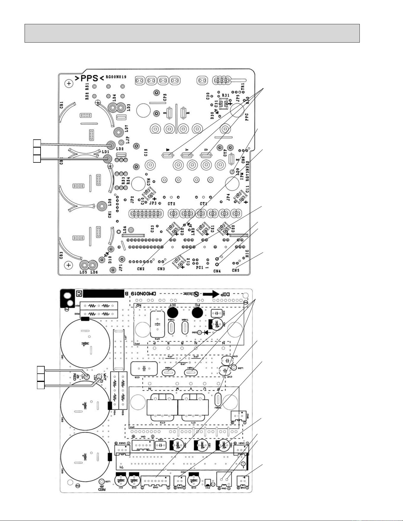
64
MUZ-A24NA MUY-A24NA
5. Outdoor power board
294-370 VDC
Output
(Red)
(White)
Connect to the compressor
Voltage among phases: 5 to 180 V
Connect to the ground
CN5
Primary current detection
(Connect to the noise filter)
CN2
Connect to the controller board
(+)1-5(–): Signal transmission
(To electronic control P.C. board)
5 V DC pulse wave
(+)2-5(–): Zero cross signal
3-4 : Not used
(+)6-5(–): 15 V
(+)7-5(–): 15 V
(+)
(–)
Signal reception (From electronic
control P.C. board)
5 V DC pulse wave
)
CN3
Fin temperature thermistor RT64
1
3
294-370 VDC
Output
Connect to the compressor
Voltage among phases: 5 to 180 V
Connect to the ground
CN5
Primary current detection
(Connect to the noise filter)
CN2
Connect to the controller board
(+)1-5(–): Signal transmission
(To electronic control P.C. board)
5 V DC pulse wave
(+)2-5(–): Zero cross signal
3-4 : Not used
(+)6-5(–): 15 V
(+)7-5(–): 15 V
Signal reception (From electronic
control P.C. board)
5 V DC pulse wave
)
CN3
Fin temperature thermistor RT64
(Red)
(White)
(+)
(–)
1
3
MUZ-A24NA MUY-A24NA MUZ-GA24NA MUY-GA24NA
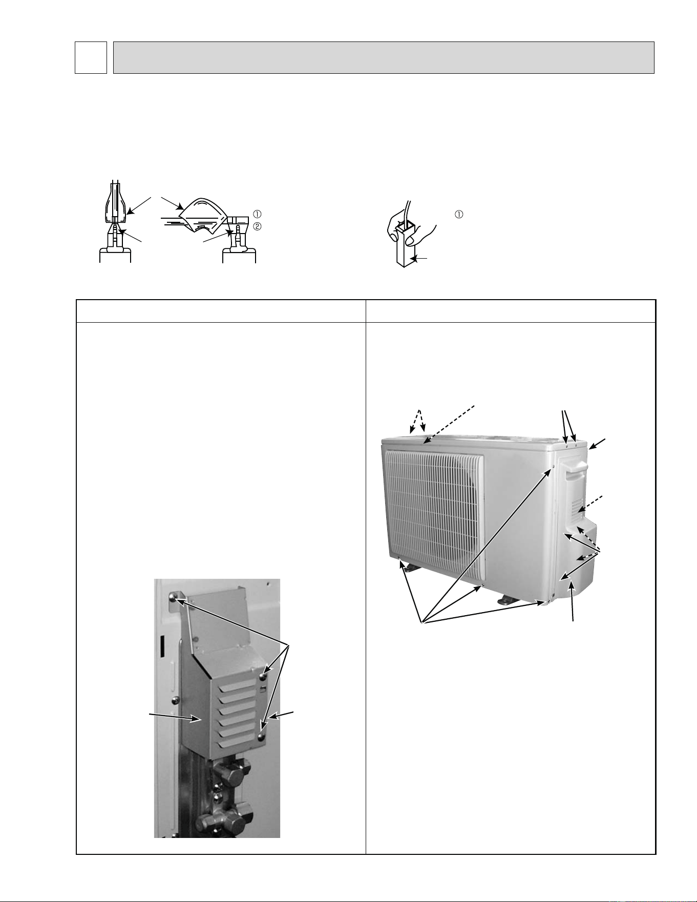
65
11-1. MUZ-A09NA MUZ-A12NA MUZ-A15NA MUZ-A17NA MUY-A15NA MUY-A17NA
NOTE: Turn OFF power supply before disassembly.
OPERATING PROCEDURE PHOTOS
1. Removing the cabinet
(1) Remove the screw fixing the service panel.
(2) Pull down the service panel and remove it.
(3) Remove the screws fixing the conduit cover.
(4) Remove the conduit cover.
(5) Disconnect the power supply wire and indoor/outdoor
connecting wire.
(6) Remove the screws fixing the top panel.
(7) Remove the top panel.
(8) Remove the screws fixing the cabinet.
(9) Remove the cabinet.
(10) Remove the screws fixing the back panel.
(11) Remove the back panel.
Photo 2
Photo 1
(1) Slide the sleeve and check if there is a locking lever or not.
(2) The terminal with this connector has the
locking mechanism.
Slide the sleeve.
Pull the terminal while
pushing the locking
lever.
Hold the sleeve, and
pull out the terminal
slowly.
Connector
Sleeve
Locking lever
DISASSEMBLY INSTRUCTIONS
11
<"Terminal with locking mechanism" Detaching points>
The terminal which has the locking mechanism can be detached as shown below.
There are two types (refer to (1) and (2)) of the terminal with locking mechanism.
The terminal without locking mechanism can be detached by pulling it out.
Check the shape of the terminal before detaching.
Conduit cover
Screw of the
conduit cover
Conduit plate
Screws of
the cabinet
Service
panel
Screw of the
cabinet
Screws
of the top
panel
Hooks
Screw of
the service
panel
Back
panel
Screws of
the top panel
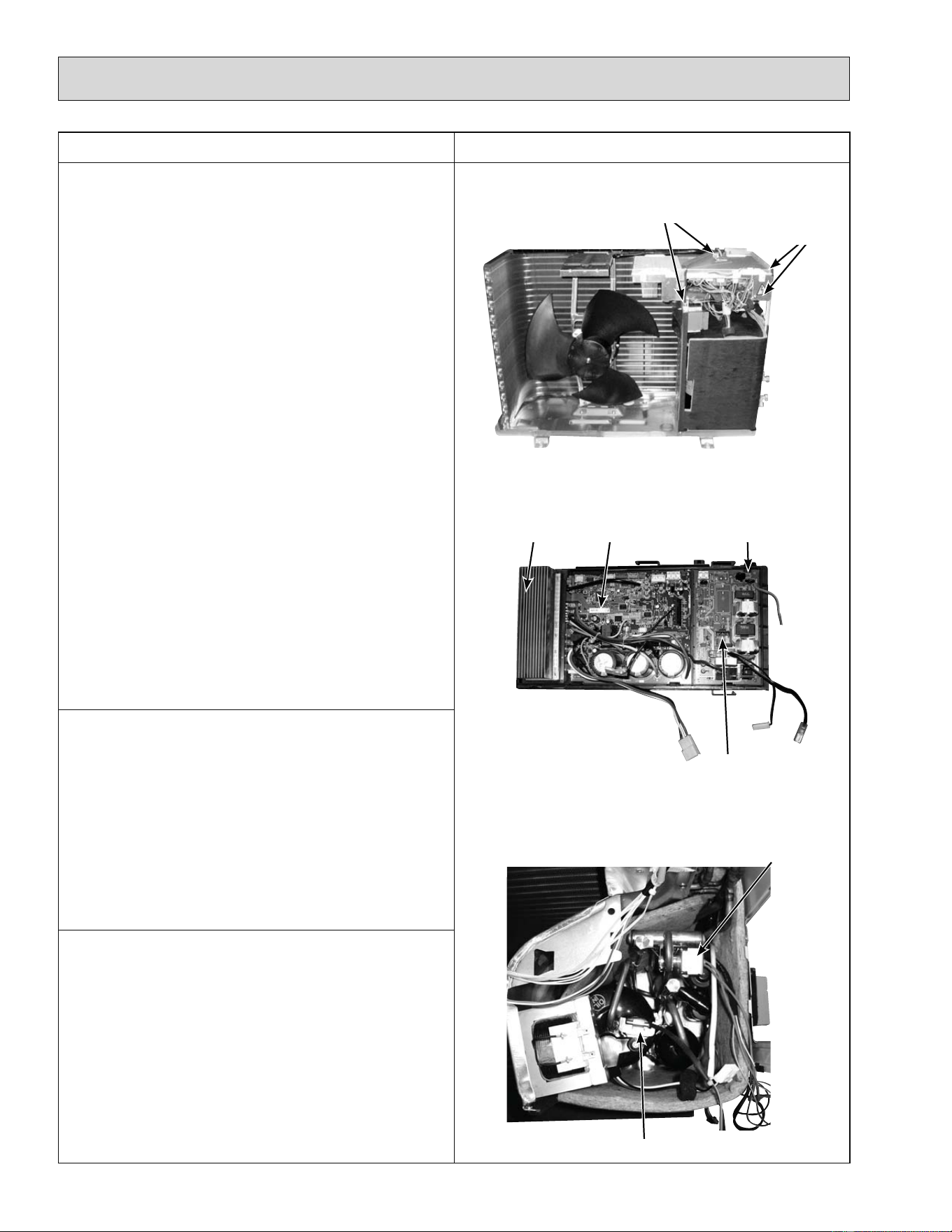
66
OPERATING PROCEDURE PHOTOS
2. Removing the inverter assembly, inverter P.C.
board and power P.C. board
(1) Remove the top panel, cabinet and service panel.
(Refer to 1.)
(2) Disconnect the power supply and indoor/outdoor con-
necting wire and remove the back panel. (Refer to 1.)
(3) Disconnect the ground wires, the lead wire to the reac-
tor and the following connectors:
<Power P.C. board>
CN721 (4-way valve coil)
<Inverter P.C. board>
CN931, CN932 (Fan motor)
CN641 (Defrost thermistor and discharge temperature
thermistor)
CN643 (Ambient temperature thermistor)
CN724 (LEV)
(4) Remove the compressor connector (CN61).
(5) Remove the screws fixing the relay panel.
(6) Remove the inverter assembly.
(7) Disconnect all connectors and lead wires on the
inverter P.C. board.
(8) Remove the inverter P.C. board from the inverter
assembly.
(9) Remove the screw fixing the power P.C. board.
(10) Disconnect all connectors and lead wires on the
power P.C. board.
(11) Remove the power P.C. board from the inverter
assembly.
Photo 3
Photo 4
Photo 5
3. Removing R.V. coil (MUZ)
(1) Remove the top panel, cabinet and service panel.
(Refer to 1.)
(2) Disconnect the power supply and indoor/outdoor con-
necting wire and remove the back panel. (Refer to 1.)
(3) Remove the inverter assembly. (Refer to 2.)
(4) Remove the R.V. coil.
4. Removing the discharge temperature thermistor
and defrost thermistor
(1) Remove the top panel, cabinet and service panel.
(Refer to 1.)
(2) Disconnect the power supply and indoor/outdoor con-
necting wire and remove the back panel. (Refer to 1.)
(3) Remove the inverter assembly. (Refer to 2.)
(4) Pull out the discharge temperature thermistor from its
holder.
(5) Pull out the defrost thermistor from its holder. (Photo 6)
Screws of
the ground
wires
Screws of the
relay panel
Heat sink
Inverter P.C.
board
Power P.C.
board
Screw of the
power P.C. board
R.V. coil
(For MUZ)
Discharge temperature thermistor
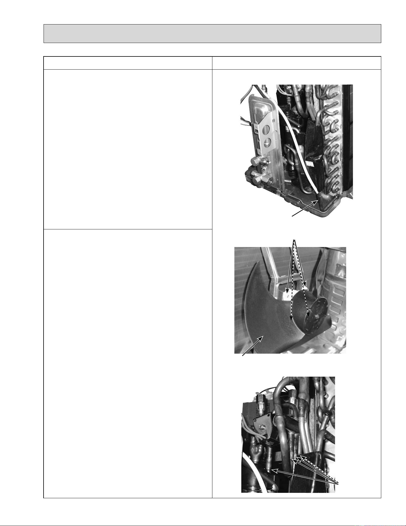
67
OPERATING PROCEDURE PHOTOS
5. Removing outdoor fan motor
(1) Remove the top panel, cabinet and service panel.
(Refer to 1.)
(2) Disconnect the power supply and indoor/outdoor con-
necting wire and remove the back panel. (Refer to 1.)
(3) Disconnect the connectors for outdoor fan motor.
(4) Remove the propeller nut.
(5) Remove the propeller.
(6) Remove the screws fixing the fan motor.
(7) Remove the fan motor.
Photo 6
Photo 7
Photo 8
6. Removing the compressor and 4-way valve
(1) Remove the top panel, cabinet and service panel.
(Refer to 1.)
(2) Disconnect the power supply and indoor/outdoor con-
necting wire and remove the back panel. (Refer to 1.)
(3) Remove the inverter assembly. (Refer to 2.)
(4) Recover gas from the refrigerant circuit.
NOTE: Recover gas from the pipes until the pressure
gauge shows 0 PSIG.
(5) Detach the brazed part of the suction and the dis-
charge pipe connected with compressor.
(6) Remove the nuts of compressor legs.
(7) Remove the compressor.
(8) Detach the brazed part of pipes connected with 4-way
valve.
Defrost
thermistor
Propeller
Screws of the outdoor fan motor
Brazed parts
of 4-way
valve
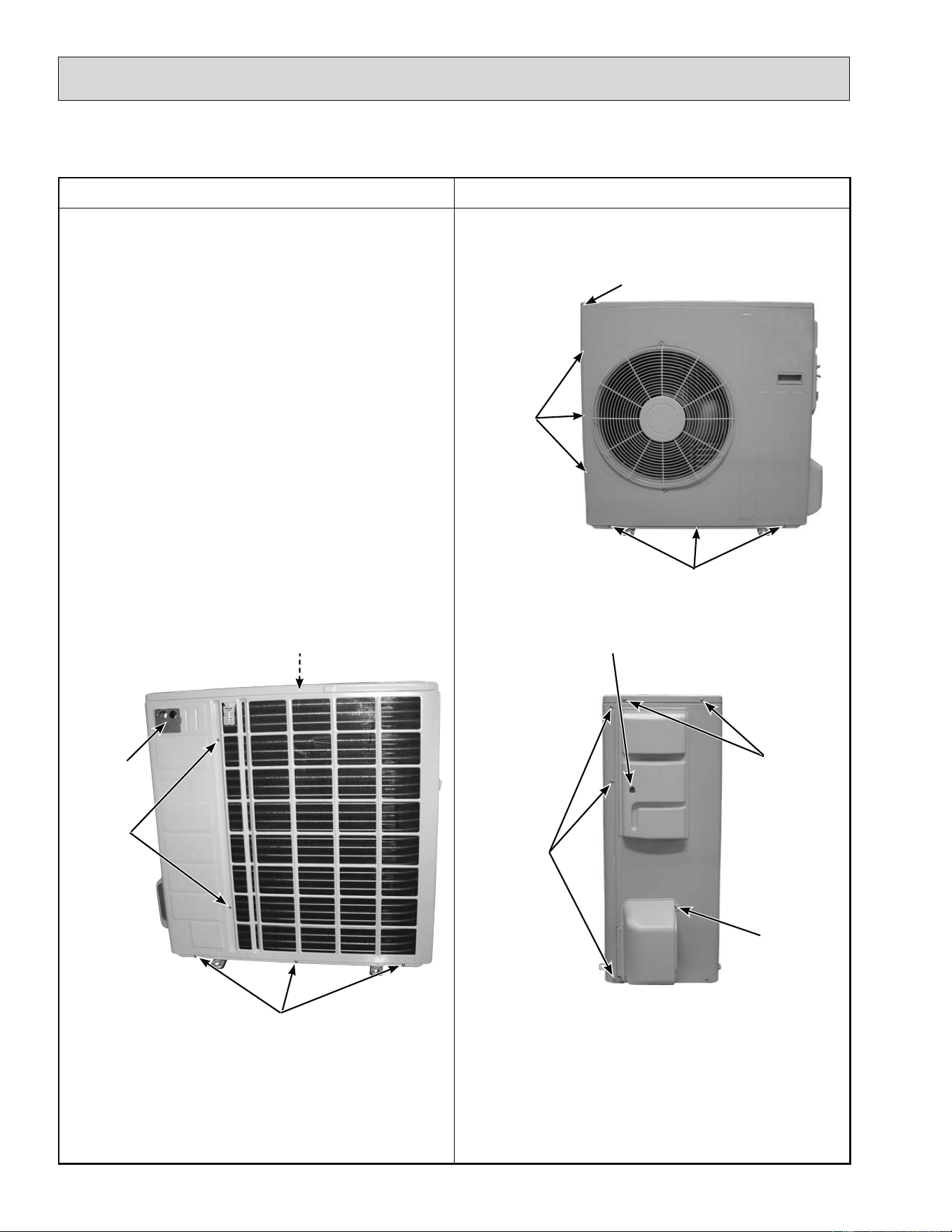
68
11-2. MUZ-A24NA MUY-A24NA MUZ-GA24NA MUY-GA24NA
NOTE: Turn OFF power supply before disassembly.
OPERATING PROCEDURE PHOTOS
1. Removing the cabinet
(1) Remove the screws of the service panel.
(2) Remove the screws of the top panel.
(3) Remove the screw of the valve cover.
(4) Remove the service panel.
(5) Remove the top panel.
(6) Remove the valve cover.
(7) Remove the screws of the cabinet.
(8) Remove the cabinet.
(9) Remove the screws of the back panel.
(10)
Remove the back panel.
Photo 3
Photo 1
Photo 2
Screws
of the
cabinet
Screw of the top panel
Screws of the cabinet
Screws
of the
cabinet
Screw of the service panel
Screws
of the
top
panel
Screw
of the
valve
cover
Screw of the motor support
Conduit plate
Screws of
the back
panel
Set screws of the back panel
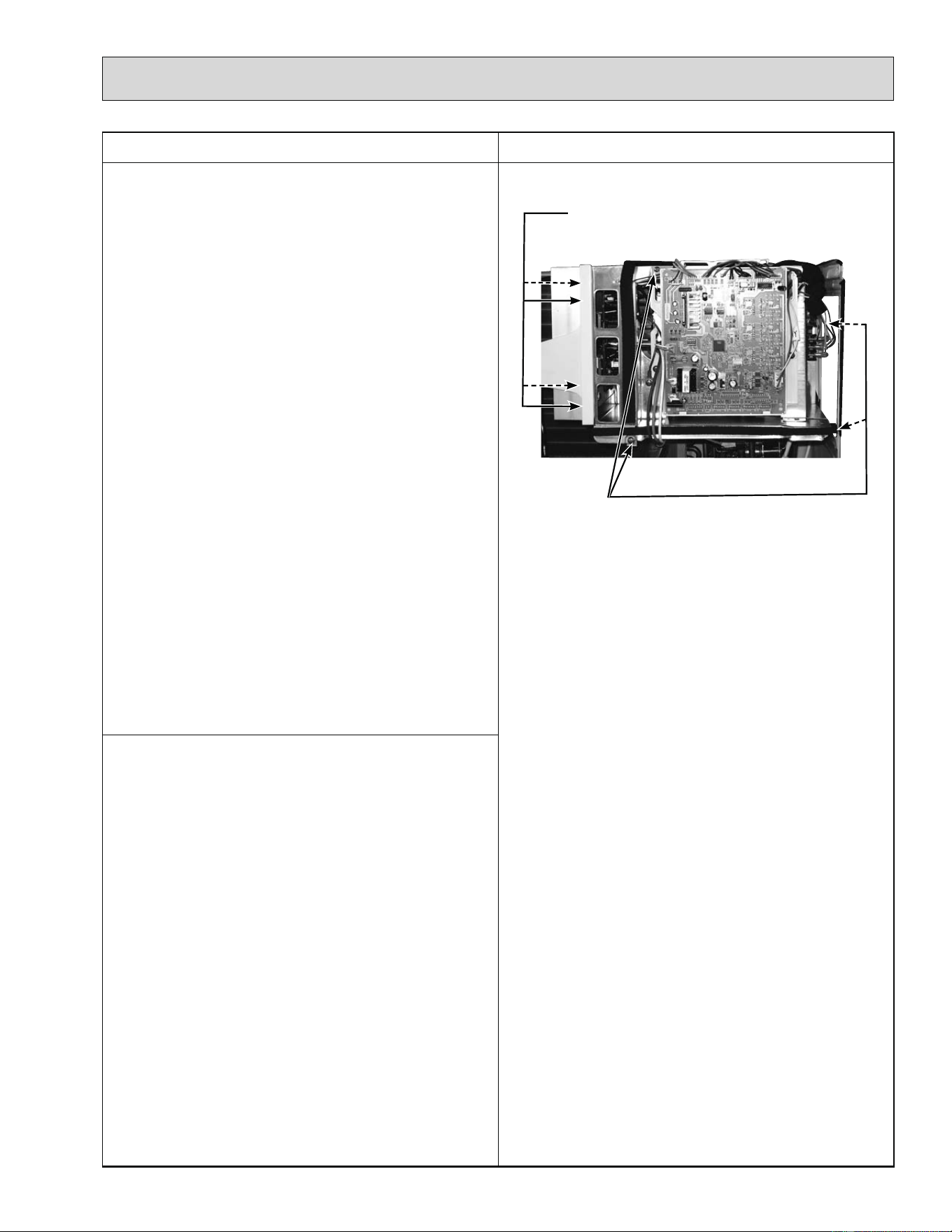
69
OPERATING PROCEDURE PHOTOS
2. Removing the inverter assembly, inverter P.C.
board and power board
(1) Remove the top panel, cabinet and service panel.
(Refer to 1.)
(2) Remove the back panel. (Refer to 1.)
(3) Disconnect the following connectors:
<Electronic control P.C. board>
CN931 and CN932 (Fan motor)
CN795 (LEV)
CN661 (Discharge temperature thermistor, defrost
thermistor (MUZ) and outdoor heat exchanger
temperature thermistor)
<Noise filter P.C. board>
CN912 (4-way valve) (MUZ)
(4) Remove the compressor connector.
(5) Remove the screws fixing the relay panel.
(6) Remove the inverter assembly.
(7) Disconnect all connectors and lead wires on the elec-
tronic control P.C. board.
(8) Remove the electronic control P.C. board from the
inverter assembly.
(9) Remove the screws fixing the power board assembly.
(10)
Disconnect all connectors and lead wires on the power
board.
(11)
Remove the power board from the inverter assembly.
(12)
Disconnect all connectors and lead wires on the noise
filter P.C. board.
(13)
Remove the noise filter P.C. board from the inverter
assembly.
Photo 4
3. Removing R.V. coil (MUZ)
(1) Remove the top panel, cabinet and service panel.
(Refer to 1.)
(2) Remove the back panel. (Refer to 1.)
(3) Remove the inverter assembly. (Refer to 2.)
(4) Remove the R.V. coil. (Photo 8)
Screws of the relay panel
Screws of the power board assembly
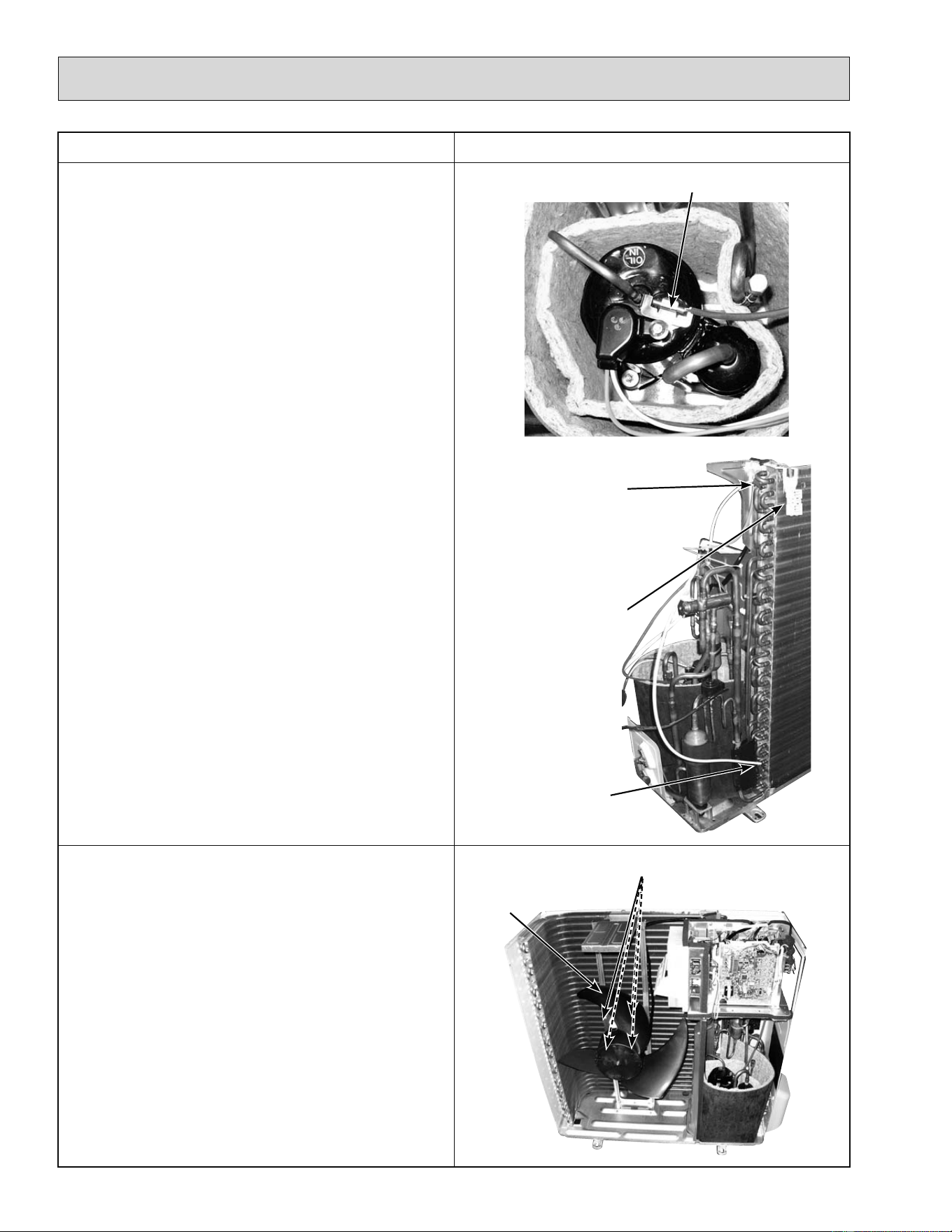
70
OPERATING PROCEDURE PHOTOS
4. Removing the defrost thermistor (MUZ), dis-
charge temperature thermistor, outdoor heat
exchanger temperature thermistor and ambient
temperature thermistor
(1) Remove the top panel, cabinet and service panel.
(Refer to 1.)
(2) Remove the back panel. (Refer to 1.)
(3) Remove the inverter assembly. (Refer to 2.)
(4) Pull out the defrost thermistor from its holder. (MUZ)
(5) Pull out the discharge temperature thermistor from its
holder.
(6) Pull out the outdoor heat exchanger temperature ther-
mistor from its holder.
(7) Pull out the ambient temperature thermistor from its
holder.
Photo 5
Photo 6
5. Removing outdoor fan motor
(1) Remove the top panel, cabinet and service panel.
(Refer to 1.)
(2) Remove the back panel. (Refer to 1.)
(3) Remove the inverter assembly. (Refer to 2.)
(4) Remove the propeller.
(5) Remove the screws fixing the fan motor.
(6) Remove the fan motor.
Photo 7
Discharge temperature thermistor
Defrost
thermistor
(For MUZ)
Outdoor heat
exchanger
temperature
thermistor
Ambient
temperature
thermistor
Propeller
Screws of the outdoor fan motor
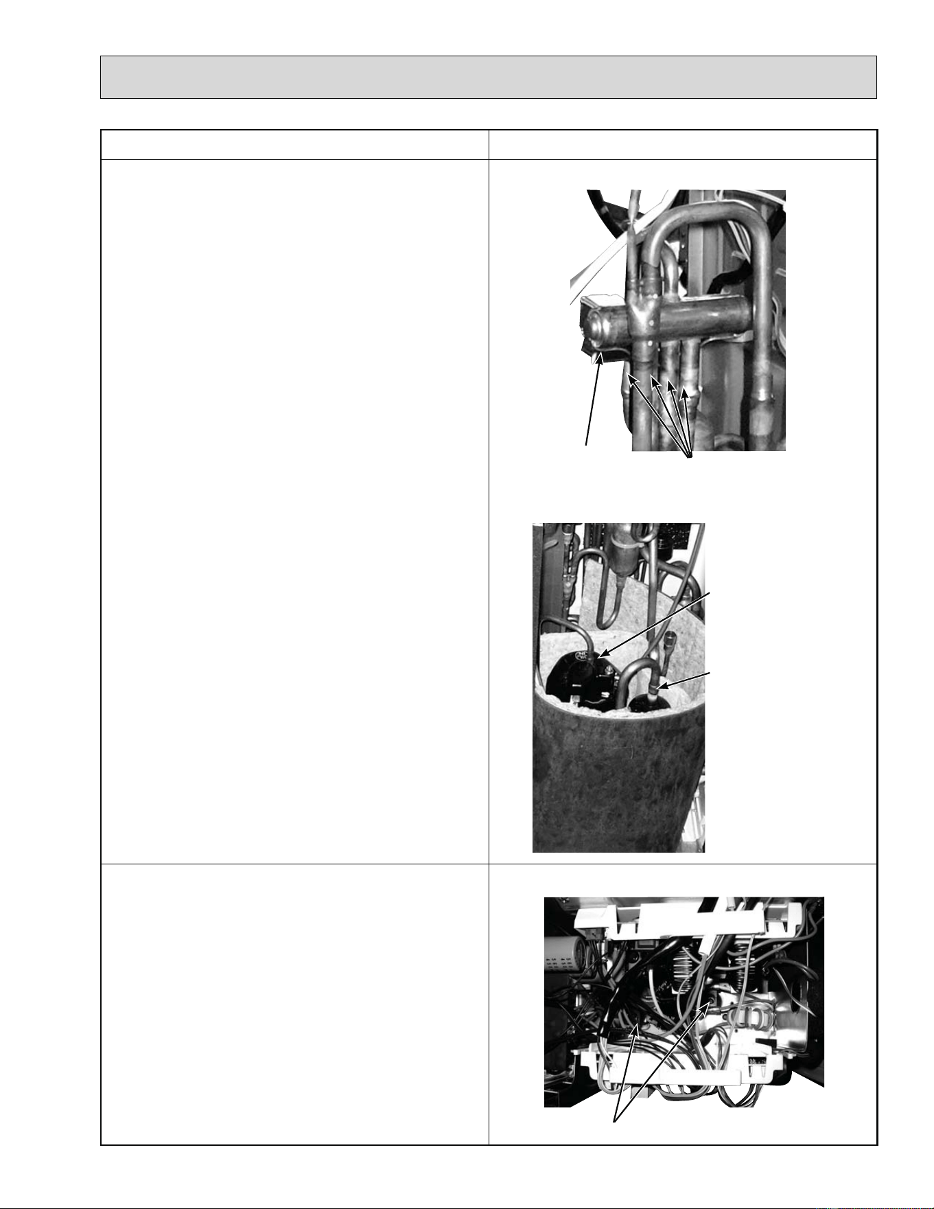
71
OPERATING PROCEDURE PHOTOS
6. Removing the compressor and 4-way valve
(1) Remove the top panel, cabinet and service panel.
(Refer to 1.)
(2) Remove the back panel. (Refer to 1.)
(3) Remove the inverter assembly. (Refer to 2.)
(4) Recover gas from the refrigerant circuit.
NOTE: Recover gas from the pipes until the pressure
gauge shows 0 PSIG.
(5) Detach the brazed part of the suction and the dis-
charge pipe connected with compressor.
(6) Remove the compressor nuts.
(7) Remove the compressor.
(8) Detach the brazed part of 4-way valve and pipe.
Photo 8
Photo 9
7. Removing the reactor
(1) Remove the top panel. (Refer to 1.)
(2) Disconnect the reactor lead wire.
(3) Remove the screws of the reactor, and remove the
reactor.
Photo 10
Screws of the reactor
Brazed part of the
discharge pipe
Brazed part of the
suction pipe
Brazed parts of 4-way valve
R.V. coil
(For MUZ)
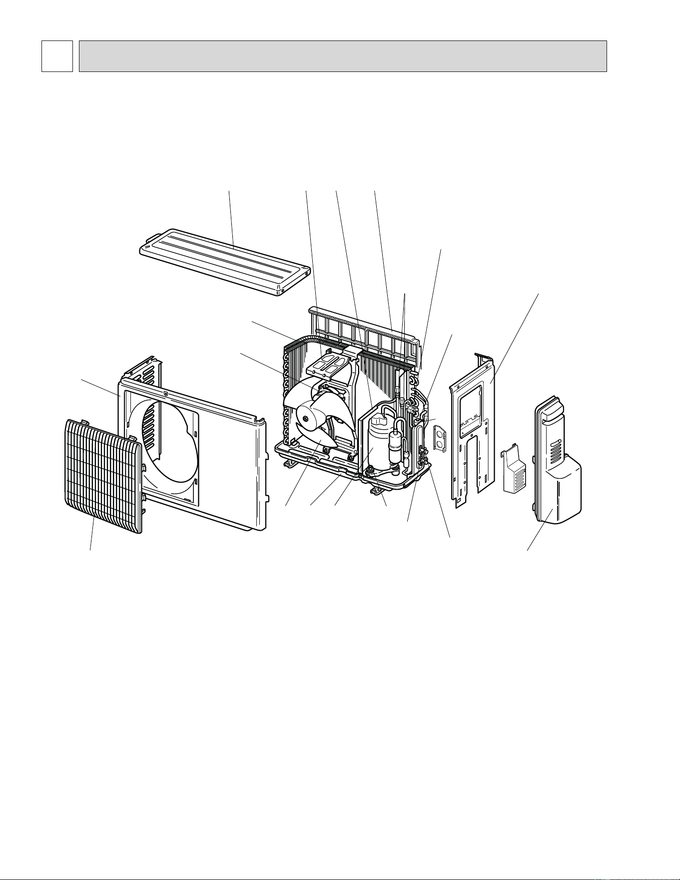
72
12-1. PARTS LIST (non-RoHS compliant)
1
2
15
17
12
10
11
MUZ-A09NA MUZ-A12NA MUZ-A15NA MUZ-A17NA MUY-A15NA MUY-A17NA
1. OUTDOOR UNIT STRUCTURAL PARTS AND FUNCTIONAL PARTS
3
4
5
6
7
8
16 14
18
19
9
13
20
PARTS LIST
12
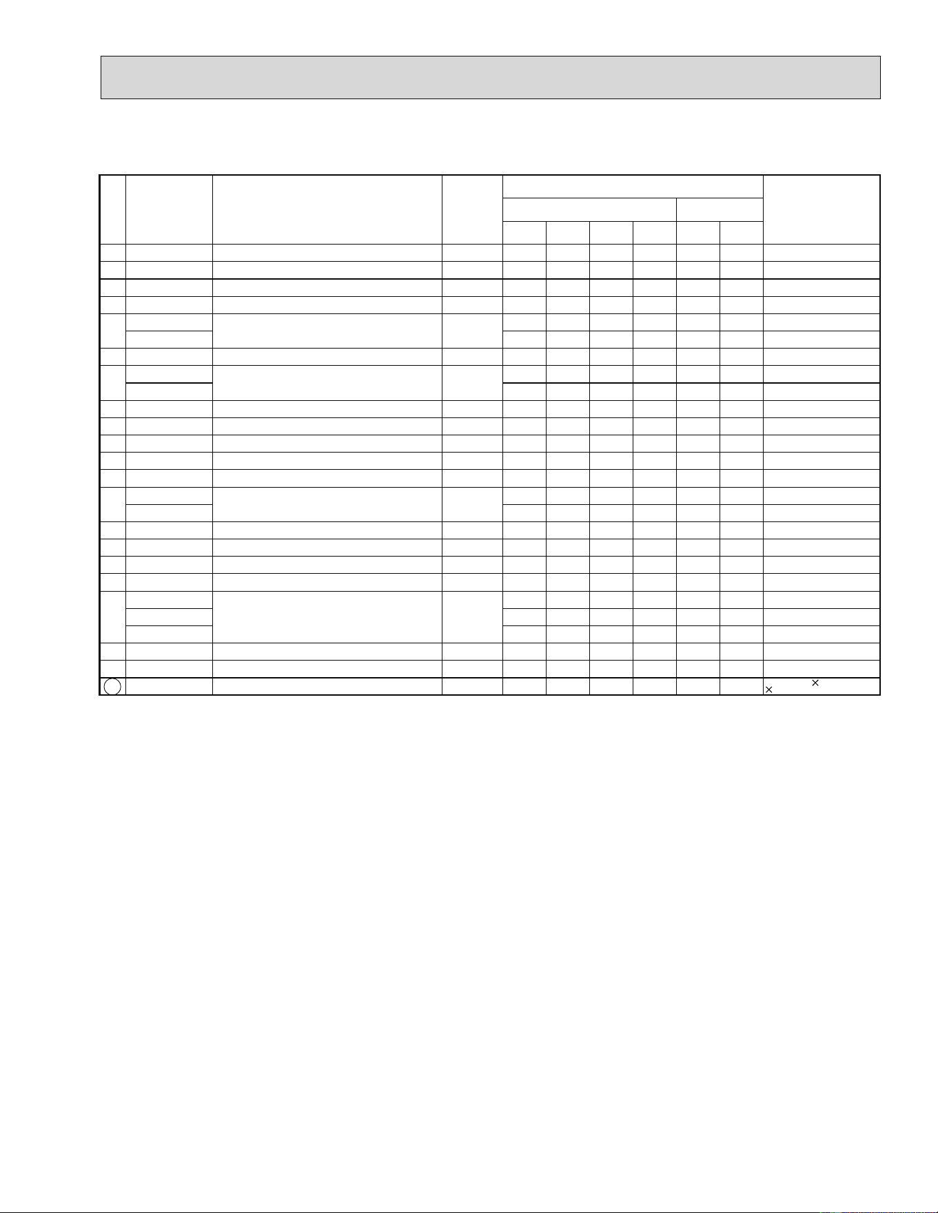
73
1. OUTDOOR UNIT STRUCTURAL PARTS AND FUNCTIONAL PARTS
Part number that is circled is not shown in the illustration.
No. Part No. Part name
Symbol
in Wiring
Diagram
Q'ty/unit
Remarks
MUZ- MUY-
A09NA A12NA A15NA A17NA A15NA A17NA
1 E02 927 232 CABINET 111111
2 E02 927 521 GRILLE 1 1 1 1 1 1
3 E02 927 501 PROPELLER 1 1 1 1 1 1
4 E02 927 290 BASE 1 1 1 1 1 1
5
E02 A54 900
COMPRESSOR MC
11
KNB092FPAH
E02 A56 900 1111
SNB130FPDH
6 E02 065 506 COMPRESSOR RUBBER SET 3 3 3333
3 RUBBERS/SET
7
E02 A54 661
STOP VALVE (GAS)
11
E02 A56 661 1111
8 E02 927 662 STOP VALVE (LIQUID) 1 1 1 1 1 1
9 E02 A49 245 SERVICE PANEL 1 11111
10 E02 A54 233 BACK PANEL 1 11111
11 E02 A54 640 EXPANSION VALVE 1 1 1 1 1 1
12 E02 927 493 EXPANSION VALVE COIL LEV 1 1 1 1 1 1
13
E02 A56 961
4-WAY VALVE
1111
E02 A54 961 1 1
14 E02 929 523 CONDENSER NET 1 1 1111
15 E02 A54 293 SEPARATOR 111111
16 E02 929 515 MOTOR SUPPORT 111111
17 E02 927 297 TOP PANEL 1 1 1 1 1 1
18
E02 A54 630
OUTDOOR HEAT EXCHANGER
11
E02 A56 630 1 1
E02 A51 630 11
19 E02 A54 301 OUTDOOR FAN MOTOR MF 111111
RC0J50-
ƑƑ
20 E02 A49 641 SERVICE PORT 2222221 PC/SET
21 E02 735 936 CAPILLARY TUBE 222222
O.D. 0.118 I.D.0.071
23-5/8

74
8
14
MUZ-A09NA MUZ-A12NA MUZ-A15NA MUZ-A17NA MUY-A15NA MUY-A17NA
2. OUTDOOR UNIT ELECTRICAL PARTS
2
3
5
6
7
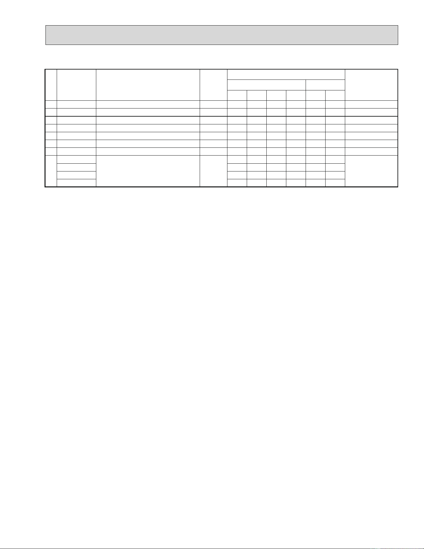
75
2. OUTDOOR UNIT ELECTRICAL PARTS
No. Part No. Part name
Symbol
in Wiring
Diagram
Q'ty/unit
Remarks
MUZ- MUY-
A09NA A12NA A15NA A17NA A15NA A17NA
1 E02 838 337 REACTOR L61 1 1 1111
2 E02 A54 444 POWER P.C. BOARD 1 11111
3 E02 A54 490 R.V. COIL 21S4 1111
4 E02 927 306 THERMISTOR SET
RT61,RT62
111111
DEFROST, DISCHARGE
5 E02 927 308
AMBIENT TEMPERATURE THERMISTOR
RT65111111
6 E02 A54 374 TERMINAL BLOCK TB1 111111
2 P
7 E02 A55 374 TERMINAL BLOCK TB2 111111
3 P
8
E02 A54 451
INVERTER P.C. BOARD
1
Including heat
sink and RT64
E02 A55 451 1
E02 A56 451 1 1
E02 A57 451 11
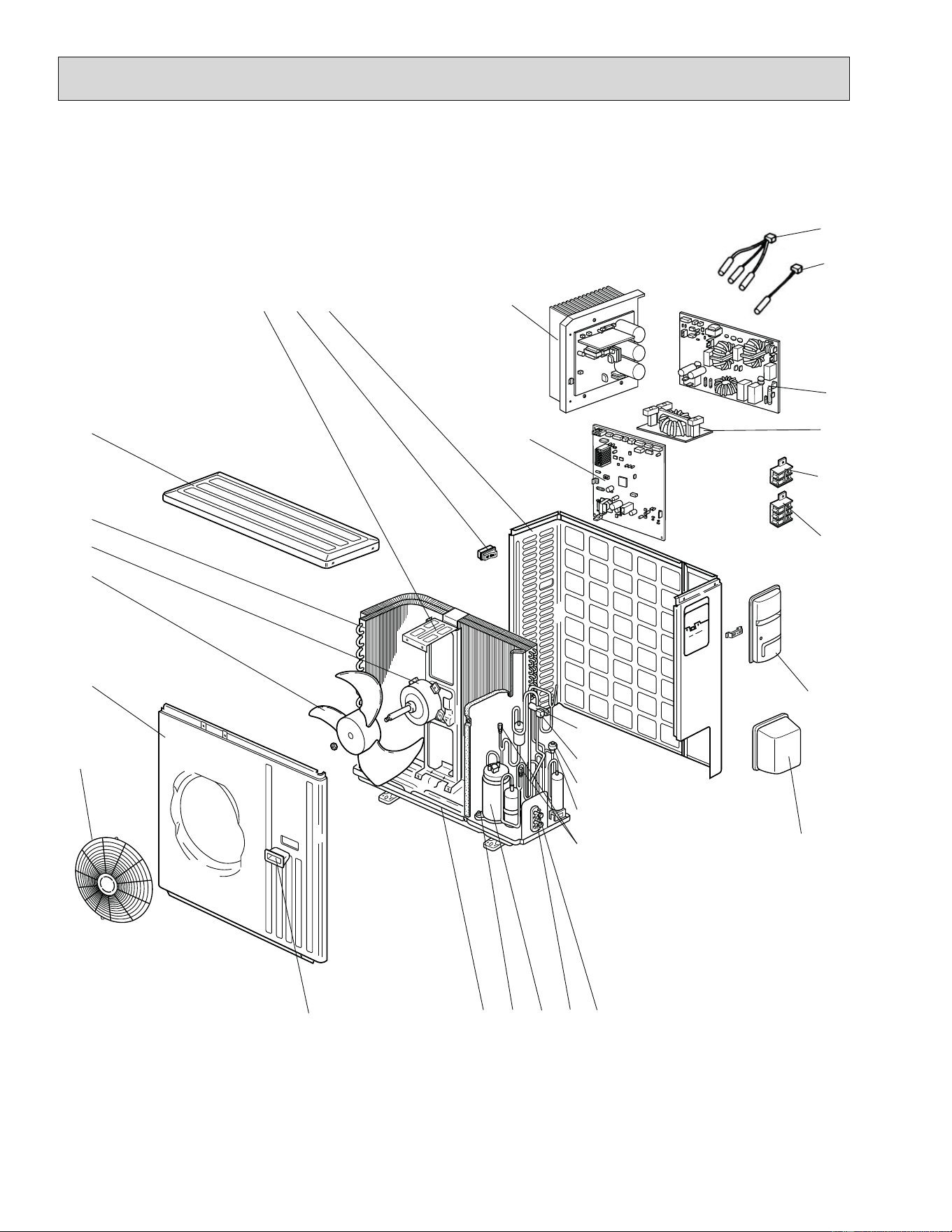
76
4
18
1
12
810
2
5
7
6
16
14
19
20
21
22
23
282930
3
MUZ-A24NA MUY-A24NA
3. OUTDOOR UNIT STRUCTURAL PARTS, ELECTRICAL PARTS AND FUNCTIONAL
PARTS
9
15
17
27
26
25
24
11
13
77
3. OUTDOOR UNIT STRUCTURAL PARTS, ELECTRICAL PARTS AND FUNCTIONAL
PARTS
Part number that is circled is not shown in the illustration.
No. Part No. Part name
Symbol
in Wiring
Diagram
Q'ty/unit
Remarks
MUZ-A24NA MUY-A24NA
1 E02 819 297 TOP PANEL 1 1
2
E02 A53 630
OUTDOOR HEAT EXCHANGER
1
E02 A58 630 1
3 E02 A58 301 OUTDOOR FAN MOTOR MF 1 1
RC0J60-
ƑƑ
4 E02 851 501 PROPELLER 1 1
5 E02 819 232 CABINET 1 1
6 E02 819 521 FAN GUARD 1 1
7 E02 819 009 HANDLE 1 1
8 E02 851 290 BASE 1 1
9 E02 065 506 COMPRESSOR RUBBER SET 3 3
3 RUBBERS/SET
10 E02 A56 900 COMPRESSOR MC 1 1
SNB130FPDH
11 E02 A58 661 STOP VALVE (GAS) 1 1
ø5/8
12 E02 821 662 STOP VALVE (LIQUID) 1 1
ø1/4
13 E02 A49 641 SERVICE PORT 2 2
1 PC/SET
14 E02 851 493 EXPANSION VALVE COIL LEV 1 1
15 E02 851 640 EXPANSION VALVE 1 1
16 E02 A58 490 R.V. COIL 21S4 1
17 E02 A56 961 4-WAY VALVE 1 1
18 E02 819 650 VALVE COVER 1 1
19 E02 819 245 SERVICE PANEL 1 1
20 E02 935 374 TERMINAL BLOCK TB2 1 1 3 P
21 E02 A53 374 TERMINAL BLOCK TB1 1 1 2 P
22 E02 851 337 REACTOR L 1 1
23
E02 A58 444
NOISE FILTER P.C. BOARD
1
E02 A53 444 1
24 E02 935 309
AMBIENT TEMPERATURE THERMISTOR
RT65 1 1
25
E02 851 308
THERMISTOR SET
RT61,RT62,RT68
1
DEFROST, DISCHARGE
OUTDOOR HEAT EXCHANGER
E02 A53 308
RT62,RT68
1
DISCHARGE
OUTDOOR HEAT EXCHANGER
26 E02 A58 440 POWER BOARD 1 1
Including heat sink and RT64
27
E02 A58 450
OUTDOOR ELECTRONIC
CONTROL P.C. BOARD
1
E02 A53 450 1
28 E02 A58 233 BACK PANEL (OUT) 1 1
29 E02 817 009 HANDLE 1 1
30 E02 851 515 MOTOR SUPPORT 1 1
31 E02 851 936
CAPILLARY TUBE (TAPER PIPE)
11
O.D. 0.142 I.D.0.094
1-31/32
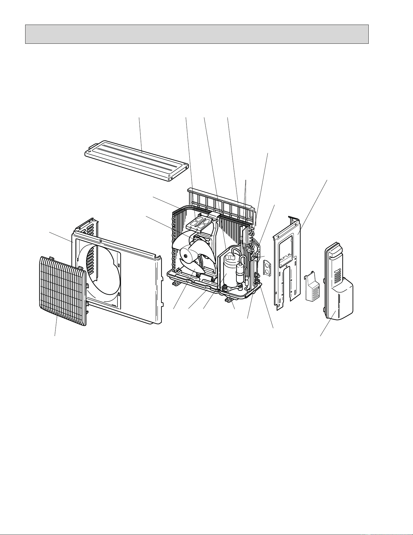
78
12-2. RoHS PARTS LIST (RoHS compliant)
1
2
15
17
12
10
11
MUZ-A09NA MUZ-A12NA MUZ-A15NA MUZ-A17NA MUY-A15NA MUY-A17NA
1. OUTDOOR UNIT STRUCTURAL PARTS AND FUNCTIONAL PARTS
3
4
5
6
7
8
16 14
18
19
9
13
20
79
1. OUTDOOR UNIT STRUCTURAL PARTS AND FUNCTIONAL PARTS
Part number that is circled is not shown in the illustration.
No.
RoHS
Part No. Part name
Symbol
in Wiring
Diagram
Q'ty/unit
Remarks
MUZ-A
MUY-A
09NA 12NA 15NA 17NA
15NA17NA
-
1
-
U1
-
U2
-
U1
-
U1
-
U1
1 G E12 927 232 CABINET 1 1 1 1 1 1 1 1 1 1 1 1
2 G E12 927 521 GRILLE 1 1 1 1 1 1 1 1 1 1 1 1
3 G E12 927 501 PROPELLER 1 1 1 1 1 1 1 1 1 1 1 1
4 G E12 927 290 BASE 1 1 1 1 1 1 1 1 1 1 1 1
5
G E12 A54 900
COMPRESSOR MC
111111
KNB092FPAH
G E12 A56 900 1 1 1 1 1 1
SNB130FPDH
6 G E12 065 506 COMPRESSOR RUBBER SET 3 3 3 3 3 3 3 3 3 3 3 3
3 RUBBERS/SET
7
G E12 A54 661
STOP VALVE (GAS)
111111
ø
3/8
G E12 A56 661 1 1 1 1 1 1
ø
1/2
8 G E12 927 662 STOP VALVE (LIQUID) 1 1 1 1 1 1111111
ø
1/4
9 G E12 A49 245 SERVICE PANEL 1 1 1 1 1 1111111
10 G E12 A54 233 BACK PANEL 1 1 1 1 1 1111111
11 G E12 A54 640 EXPANSION VALVE 1 1 1 1 1 1111111
12 G E12 927 493 EXPANSION VALVE COIL LEV 1 1 1 1 1 1111111
13
G E12 A56 961
4-WAY VALVE
111111
G E12 A54 961 1 1 1 1 1 1
14
G E12 929 523
CONDENSER NET
1 1 11111111
G E12 838 523 1 1
15
G E12 A54 293
SEPARATOR
1 1 11111111
G E12 B49 293 1 1
16
G E12 929 515
MOTOR SUPPORT
1 1 11111111
G E12 927 515 1 1
17 G E12 927 297 TOP PANEL 1 1 1 1 1 1 1 1 1111
18
G E12 A54 630
OUTDOOR HEAT EXCHANGER
1111
G E12 A56 630 1 1 1 1
G E12 A51 630 11
G E12 B49 630 1 1
19 G E12 A54 301 OUTDOOR FAN MOTOR MF 1 1 1 1 1 1 1 1 1 1 1 1 RC0J50-
ƑƑ
20 G E12 A49 641 SERVICE PORT 2 2 2 2 2 2 2 2 2 2 2 2 1 PC/SET
21
G E12 735 936
CAPILLARY TUBE
2 2 22222222
O.D. 0.118 I.D.0.071
23-5/8
G E12 927 937 1 1
O.D. 0.118 I.D.0.079
9-7/16
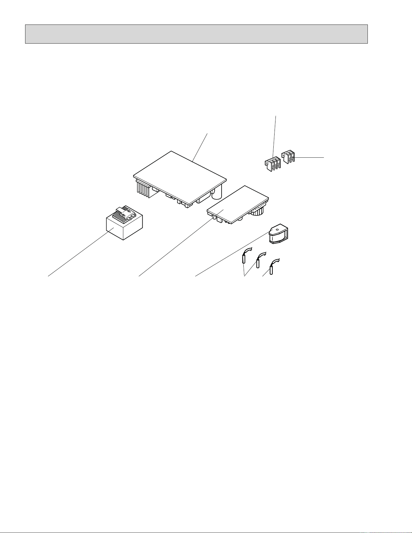
80
8
14
MUZ-A09NA MUZ-A12NA MUZ-A15NA MUZ-A17NA MUY-A15NA MUY-A17NA
2. OUTDOOR UNIT ELECTRICAL PARTS
2
3
5
6
7
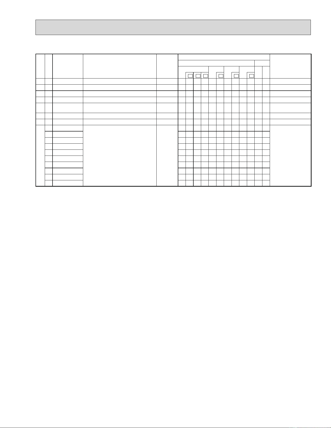
81
2. OUTDOOR UNIT ELECTRICAL PARTS
No.
RoHS
Part No. Part name
Symbol
in Wiring
Diagram
Q'ty/unit
Remarks
MUZ-A
MUY-A
09NA 12NA 15NA 17NA
15NA17NA
-
1
-
U1
-
U2
-
U1
-
U1
-
U1
1 G E12 838 337 REACTOR L61 1 1 1 1 1 1 1 1 1 1 1 1
2 G E12 A54 444 POWER P.C. BOARD 1 1 1 1 1 1 1 1 1 1 1 1
3 G E12 A54 490 R.V. COIL 21S4 1 1 1 1 1 1 1 1 1 1
4 G E12 927 306 THERMISTOR SET
RT61,RT62
111111111111
DEFROST, DISCHARGE
5 G E12 927 308
AMBIENT TEMPERATURE
THERMISTOR
RT65 111111111111
6 G E12 A54 374 TERMINAL BLOCK TB1 1 1 1 1 1 1 1 1 1 1 1 1
2 P
7 G E12 A55 374 TERMINAL BLOCK TB2 1 1 1 1 1 1 1 1 1 1 1 1
3 P
8
G E12 A54 451
INVERTER P.C. BOARD
1
Including heat
sink and RT64
G E12 B49 451 1
G E12 A55 451 1
G E12 A56 451 1 1
G E12 A57 451 11
G E12 B09 451 1
G E12 B51 451 1
G E12 B10 451 1
G E12 B11 451 1
G E12 B12 451 1
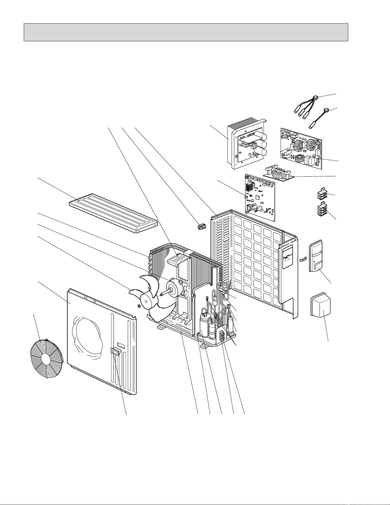
82
4
18
1
12810
2
5
7
6
16
14
19
20
21
22
23
282930
3
MUZ-A24NA MUY-A24NA MUZ-GA24NA MUY-GA24NA
3. OUTDOOR UNIT STRUCTURAL PARTS, ELECTRICAL PARTS AND FUNCTIONAL
PARTS
9
15
17
27
26
25
24
11
13
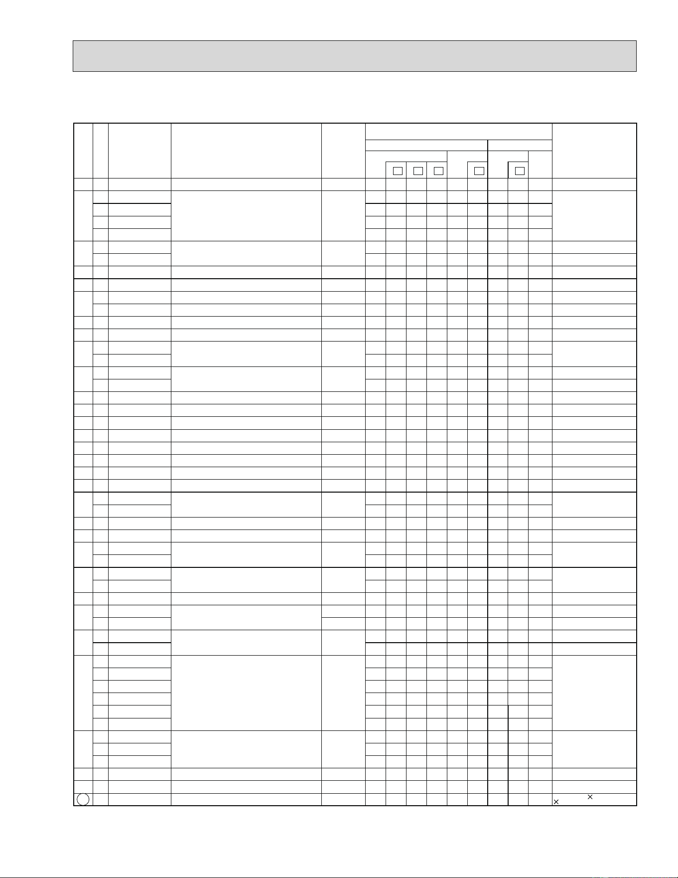
83
3.
OUTDOOR UNIT STRUCTURAL PARTS, ELECTRICAL PARTS AND FUNCTIONAL PARTS
Part number that is circled is not shown in the illustration.
No.
RoHS
Part No. Part name
Symbol
in Wiring
Diagram
Q'ty/unit
Remarks
MUZ- MUY-
A24NA
GA24NA
A24NA
GA
24NA
-
1
-
U1
-
U2
-
U1
-
1
1 G E12 819 297 TOP PANEL 111111111
2
G E12 A53 630
OUTDOOR HEAT EXCHANGER
11
G E12 A58 630 1 1 1 1
G E12 E34 630 1 1
G E12 E35 630 1
3
G E12 A58 301
OUTDOOR FAN MOTOR MF
1 1 1 1 1 1 RC0J60-
ƑƑ
G E12 E34 301 1 1 1 RC0J77-
ƑƑ
4 G E12 851 501 PROPELLER 111111111
5 G E12 819 232 CABINET 111111111
6
G E12 D84 521 FAN GUARD 1 1 1 1 1 1
Including ice guard
G E12 819 521 FAN GUARD 1 1 1
7 G E12 819 009 HANDLE 1 1 1 11111 1
8 G E12 851 290 BASE 1 1 1 11111 1
9
G E12 065 506
COMPRESSOR RUBBER SET
33 3
3 RUBBERS/SET
G E12 C34 506 3 3 3 3 3 3
10
G E12 A56 900
COMPRESSOR MC
1111 11
SNB130FPDH
G E12 E34 900 1 1 1
SNB130FQBH
11 G E12 A58 661 STOP VALVE (GAS) 11111111 1
ø5/8
12 G E12 821 662 STOP VALVE (LIQUID) 1 1 1 111111
ø1/4
13 G E12 A49 641 SERVICE PORT 2 2 2 222222
1 PC/SET
14 G E12 851 493 EXPANSION VALVE COIL LEV 1 1 1 11111 1
15 G E12 851 640 EXPANSION VALVE 1 1 1 11111 1
16 G E12 A58 490 R.V. COIL 21S4 1 1 1 1 1 1
17 G E12 A56 961 4-WAY VALVE 1 1 1 11111 1
18 G E12 819 650 VALVE COVER 1 1 1 111111
19
G E12 819 245
SERVICE PANEL
1111 11
G E12 D20 245 1 1 1
20 G E12 935 374 TERMINAL BLOCK TB2 1 1 1 111111
3 P
21 G E12 A53 374 TERMINAL BLOCK TB1 1 1 1 111111
2 P
22
G E12 851 337
REACTOR L
1111 11
G E12 A87 337 1 1 1
23
G E12 A58 444
NOISE FILTER P.C. BOARD
111111
G E12 A53 444 111
24 G E12 935 309
AMBIENT TEMPERATURE THERMISTOR
RT65 111111111
25
G E12 851 308
THERMISTOR SET
RT61,RT62,RT68
111111
DEFROST, DISCHARGE
OUTDOOR HEAT EXCHANGER
G E12 A53 308
RT62,RT68
111
DISCHARGE
OUTDOOR HEAT EXCHANGER
26
G E12 A58 440
POWER BOARD
1111 11
Including heat sink and RT64
G E12 E34 440 1 1 1
27
G E12 A58 450
OUTDOOR ELECTRONIC
CONTROL P.C. BOARD
11
G E12 A53 450 11
G E12 B13 450 1 1
G E12 E34 450 1
G E12 E37 450 1
G E12 E35 450 1
28
G E12 A58 233
BACK PANEL (OUT)
11 1
G E12 D91 233 1 1 1
G
E12 E34 233
11 1
29 G E12 817 009 HANDLE 11111111 1
30 G E12 851 515 MOTOR SUPPORT 11111111 1
31 G E12 851 936
CAPILLARY TUBE (TAPER PIPE)
111111111
O.D. 0.142 I.D.0.094
1-31/32
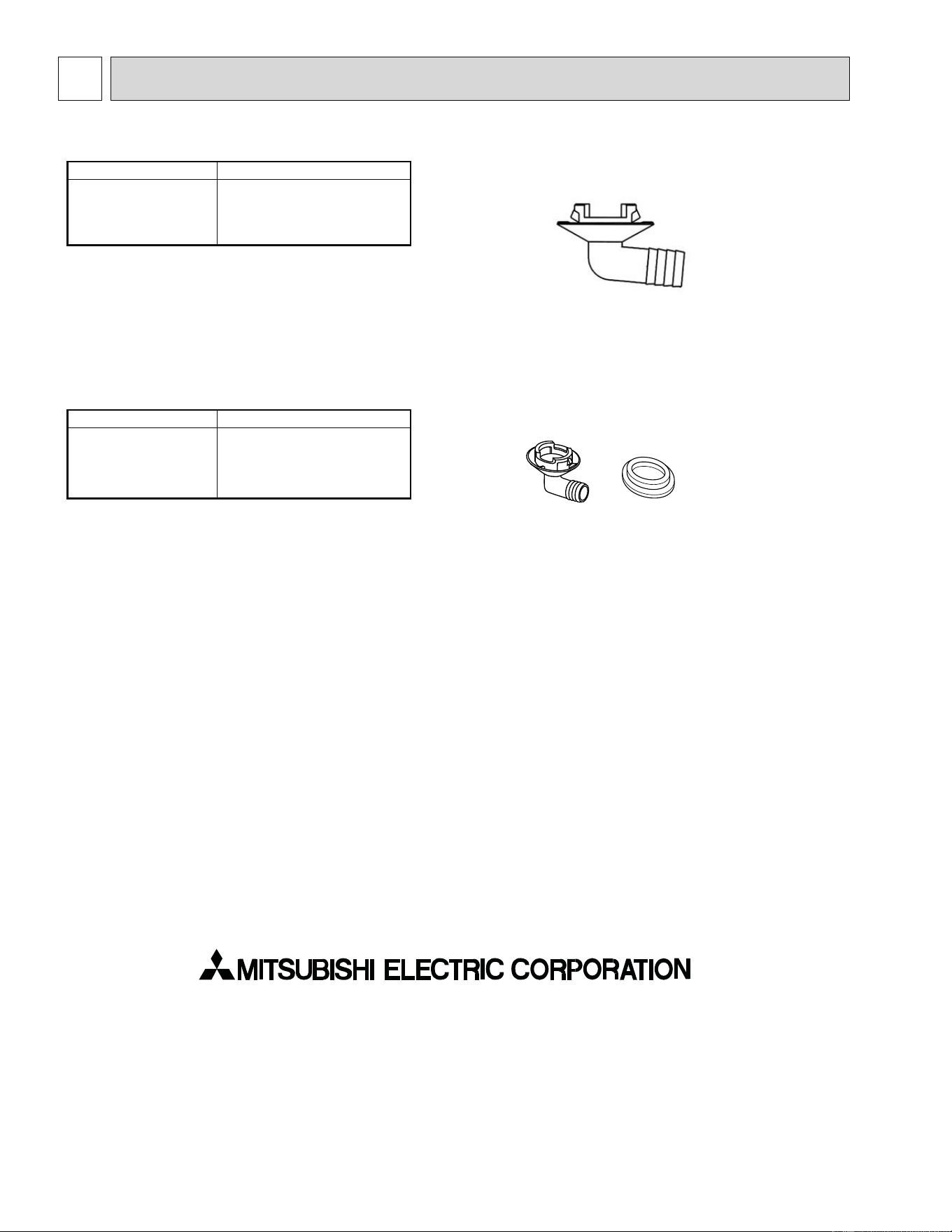
13-1. DRAIN SOCKET
Model Part No.
MUZ-A09/12/15/17NA
MUY-A15/17NA
MAC-851DS
13-2. DRAIN SOCKET ASSEMBLY
Model Part No.
MUZ-A24NA
MUY-A24NA
MUZ-GA24NA
MUY-GA24NA
MAC-811DS
HEAD OFFICE: TOKYO BLDG., 2-7-3, MARUNOUCHI, CHIYODA-KU, TOKYO 100-8310, JAPAN
© Copyright 2006 MITSUBISHI ELECTRIC CO.,LTD
Distributed in Jun. 2011. No. OB451 REVISED EDITION-G
Distributed in Jun. 2010. No. OB451 REVISED EDITION-F 5
Distributed in Mar. 2009. No. OB451 REVISED EDITION-E 4
Distributed in May 2008. No. OB451 REVISED EDITION-D 6
Distributed in Nov. 2007. No. OB451 REVISED EDITION-C 7
Distributed in Feb. 2007. No. OB451 REVISED EDITION-B 7
Distributed in Sep. 2006. No. OB451 REVISED EDITION-A 7
Distributed in Apr. 2006. No. OB451 7
Made in Japan
New publication, effective Jun. 2011
Specifications subject to change without notice.
OPTIONAL PARTS
13