
User Manual
ParkAlert Front Sensor System
with Buzzer or Display
PS-FBP
PS-FDIS

2
Installation Guide
tel - 1-800-477-2267 (East Coast) - 1-888-883-2790 (West Coast)
email - [email protected] (US)
email - [email protected] (Europe)
PS-FBP/PS-FDIS
ParkAlert Front Sensor System
with Buzzer or Display
Introduction
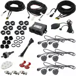
Box Contents
Key Features
u Triangulation technology
u 2 or 4 sensor installation
u Low prole, paintable sensors
u Wide detection angle with minimal blind area
u OE sounding tone
u Self-diagnostic mode at startup
u Compatible with optional display
(P/N: PA-DISPLAY)
u 4 Bumper Mount Sensors with 18” Pigtail
u 4 Black Rubber Seals
u 4 6° Sensor Sleeves
u 4 12° Sensor Sleeves
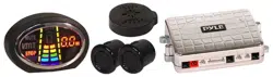
u Control Module
u Speaker with Volume Control
u Power Harness
u 22.5mm Hole Saw
u Accessory Pack
u Measuring Tape
u User Manual
u Warranty Card
Congratulations on purchasing EchoMaster PRO parking sensors.
This ultrasonic detection system is designed to assist in the avoidance
of obstacles while parking.
Disclaimer:
EchoMaster® is strictly a driver assistance device, and should not be relied upon as a substitute for safe driving
practices. Use common sense when parking and always follow recommended safe driving guidelines from your local,
State and County Department of Motor Vehicles regarding parking procedures. To help prevent accidents, always
use caution when parking, looking visually to ensure your path is clear. Keep speeds under three miles per hour. The
owner shall not be entitled to recover from the Company, its successors or assignees, incidental and consequential
damages, such as personal injury, loss of income, loss of time, loss of prots, loss of vehicle use or property damage.
No employee, agent or representative of the Company of the Selling Retailer may modify, alter or extend this Warranty
in any way. This Warranty gives you specic legal rights. You may also have other rights under this Warranty which
may vary from state to state.
Note: Under no circumstances should you attempt to open the control box or any other component. Doing so will void
all manufacturer’s warranties.
This manual covers products:
PS-FBP-B (ParkAlert Front Sensor System with Buzzer - Gloss Black sensors)
PS-FBP-M (ParkAlert Front Sensor System with Buzzer - Matte Black sensors)
PS-FBP-S (ParkAlert Front Sensor System with Buzzer - Silver sensors)
PS-FBP-W (ParkAlert Front Sensor System with Buzzer - White sensors)
PS-FDIS-B (ParkAlert Front Sensor System with Display - Gloss Black sensors)
PS-FDIS-M (ParkAlert Front Sensor System with Display - Matte Black sensors)
PS-FDIS-S (ParkAlert Front Sensor System with Display - Silver sensors)
PS-FDIS-W (ParkAlert Front Sensor System with Display - White sensors)

3
Installation Guide
tel - 1-800-477-2267 (East Coast) - 1-888-883-2790 (West Coast)
email - [email protected] (US)
email - [email protected] (Europe)
Fitting Instructions
PS-FBP/PS-FDIS
ParkAlert Front Sensor System
with Buzzer or Display
Recommended Tools
for Installation
u High torque drill, use slow speed
(approx 400 rpm)
u Grease Pencil and Center Punch
for marking drill point
u 1/8” carbide tipped drill bit for
starting pilot hole
u Hole Saw 22.5mm (Included)
u Pliers, Crimpers & Soldering Iron
u Multi-Meter
u Zinc Galvanizer or a rust inhibitor
for metal (OPT P/N: EMZ)
u Safety goggles
u Angle Gauge Sleeve Selector (OPT P/N: SP1022)
u Measuring Tape
Optional Tools
u Panel tool (for situations requiring plastic, inner
panels to be removed)
u Phillips head tip for drill
u Wire pulling tool (for routing wires)/ Fishing tool
u Semi-circular metal le (for smoothing hole
edges when necessary)- DO NOT use ngers
to test holes for burrs or smoothness.
EDGES ARE SHARP!!!
Determining Sensor Position: Measure Twice, Cut Once!
NOTE: Test the system functionality PRIOR to drilling holes in the bumper. There may
be some OEM features in the vehicle that interfere with the sensor system.
Inspect behind the bumper in the approximate mounting area to check for any
possible obstructions.
A proper installation will take into consideration two factors:
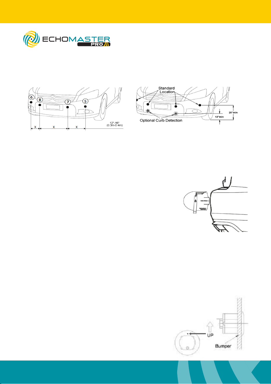
(1) Placement: height and distance either side of bumper center.
(2) Angle: accurate detection depends on the correct sensor angle.
The sensors need a 1” clearance space behind the bumper to be completely inserted.
Some bumpers have an outside cover or fascia and a metal backing. You may have to
drill through both layers to ensure you have enough clearance in order to t the
sensors. Other bumpers require some removal of foam backing.
CAUTION: Be careful of hot engine parts and/or sharp edges under bumper.
4
Installation Guide
tel - 1-800-477-2267 (East Coast) - 1-888-883-2790 (West Coast)
email - [email protected] (US)
email - [email protected] (Europe)
Fitting Instructions - (continued)
Sensor Install: Sensors must be installed from left to right (in this order: 6-8-7-5) with
control module harness entering vehicle near sensor #5. If only using 2 sensors for the
install, it is recommended to use sensors 7 and 8.
Choosing the Correct Angle Sleeve (Optional angle gauge: SP1022)
Vehicle is parked on at and level ground and
the parking brake is set. Place the Angle Gauge
at against the surface of the bumper. The
swingarm will point to the correct measurement.
DO NOT CONTINUE TO NEXT STEP IF ARM
FALLS BEYOND THE LAST LINE ON THE MARKER!
This means that the placement is too steep; re-evaluate
placement and nd a better area.
Drilling Holes and Installing Sensors
NOTE: Test the system functionality PRIOR to drilling holes in the bumper. There
may be some OEM features in the vehicle that interfere with the sensor system.
Warnings / Precautions: Please consult with us before installing on a vehicle with any
rear or front mounted external appliances, like spare tires, bike racks, brush guards,
etc, which may interfere with the system’s detection and cause false detection.
Using the provided Hole Saw, cut the
sensor holes. Always wear approved
safety glasses when drilling and use
caution. If drilling a metal bumper, coat
edges of holes with Zinc Galvanizer, a
rust inhibitor.
Ensure correct angle sleeve
is being used. Insert sensor
with the “up” marking
facing up.
(2) Mount Sensor
(1) The Sensor Holes
PS-FBP/PS-FDIS
ParkAlert Front Sensor System
with Buzzer or Display
5
Installation Guide
tel - 1-800-477-2267 (East Coast) - 1-888-883-2790 (West Coast)
email - [email protected] (US)
email - [email protected] (Europe)
Fitting Instructions - (continued)
NOTE: It is recommended to solder all connections.
Running Sensors to Control Module
Many vehicles will have factory grommets to allow routing of wires from the outside to the
inside of the vehicle. If you are drilling a hole through a metal body panel to route your sensor
wires into the passenger compartment, determine where the sensor wires will enter into the
passenger compartment and route to control module.
Mounting Speaker
The speaker has 3 adjustment positions: Hi, Low, and Off. You usually want to keep the speaker
on the same side of the vehicle as the control module for ease. Clean the mounting area with the
supplied alcohol pad, afx adhesive to the back of the speaker, and rmly press the speaker into
place. Route speaker cable to control module and plug into power harness.
If using Display, please refer to PA-DISPLAY user manual for mounting instructions.
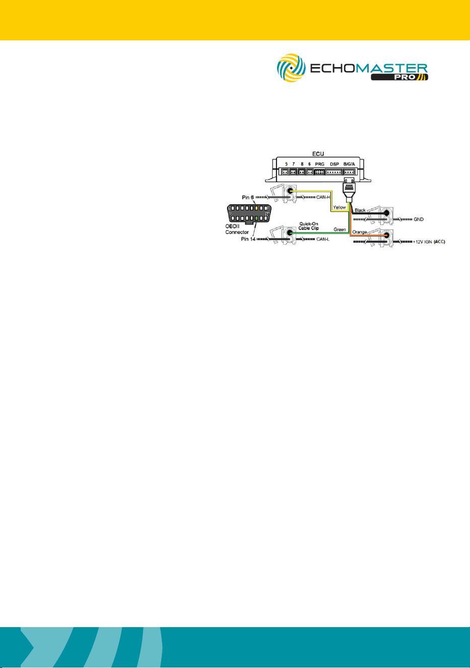
Connecting the Power Harness
Mounting Control Module
You will want to mount the control module in the passenger compartment, in/under/behind the
dashboard. Clean a suitable location using the provided alcohol swab. Plug in all the wires, ad-
just dip switches, then peel backing of Velcro liner to mount. Finish by securing any loose and/or
excess wiring. Before reassembling any panels that might have been removed from the vehicle,
test the system.
PS-FBP/PS-FDIS
ParkAlert Front Sensor System
with Buzzer or Display
The control module gets power from the
ignition circuit. To nd ignition, start by
locating the ignition harness in the dash
area, usually by the steering column. Using
a test meter, nd the wire that is 12 volts
when the key is turned to the run position
and during start.
This system is fully automatic. It is on when
the vehicle ignition is on. It is active when
the speed is below 6 mph. It is in standby
mode when above 10 mph.
To detect speed you need to connect to the
CAN-H (Pin 6) and CAN-L (Pin 14) on the OBDII
connector
6
Installation Guide
tel - 1-800-477-2267 (East Coast) - 1-888-883-2790 (West Coast)
email - [email protected] (US)
email - [email protected] (Europe)
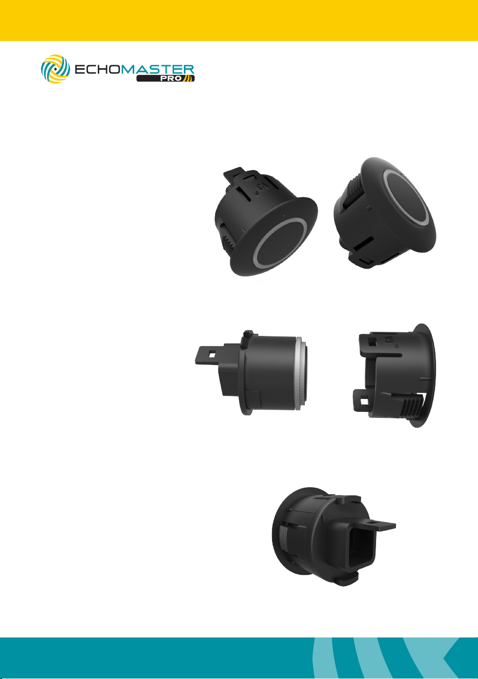
Sensor Assembly
Step 1
To take the sleeve off of the
sensors lift up on 1 clip and
push the sensor out with
your thumb.
Step 2
Slide the sensor angle
sleeves onto the sensors.
The embossed angle
measurement should be on
the same side as the clip.
Step 3
Ensure that the arrow
molded into the back of the
sensor points to the line on
the angle sleeve.
PS-FBP/PS-FDIS
ParkAlert Front Sensor System
with Buzzer or Display
7
Installation Guide
tel - 1-800-477-2267 (East Coast) - 1-888-883-2790 (West Coast)
email - [email protected] (US)
email - [email protected] (Europe)
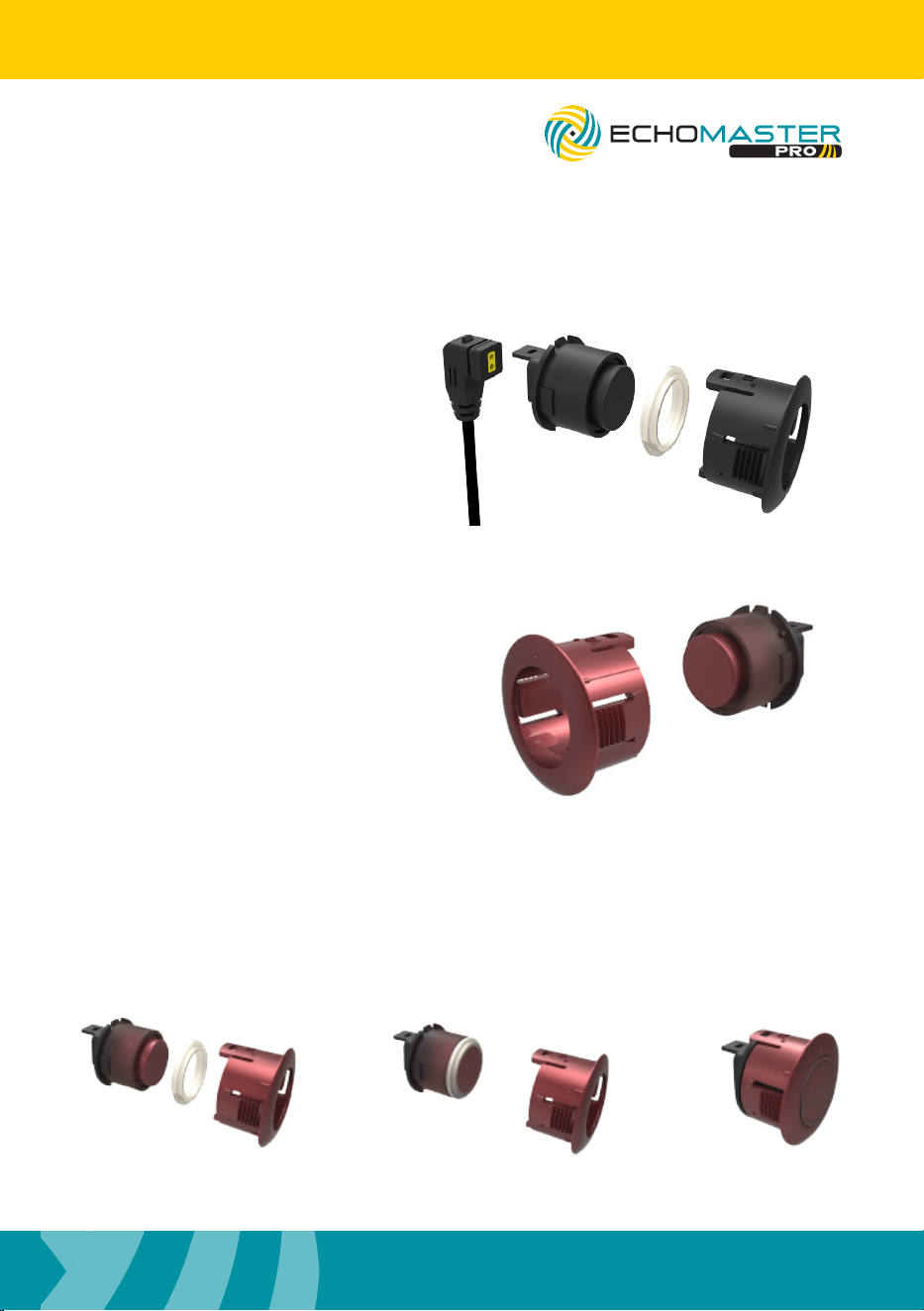
Sensor Painting
Step 1
Remove the silicon gasket
and disconnect cable before
painting the sensors.
Certain colors may require a
thin coat of primer.
Step 2
Paint the front of the sensors and the
angle sleeve. Avoid getting excessive
paint on the back of the sensors.
Paint thickness should not exceed
1mm or sensors may not function
properly.
Note: Gasket is only removable on
paintable sensors.
Step 3
After the paint has fully dried, reassemble the sensors as shown below.
PS-FBP/PS-FDIS
ParkAlert Front Sensor System
with Buzzer or Display
8
Installation Guide
tel - 1-800-477-2267 (East Coast) - 1-888-883-2790 (West Coast)
email - [email protected] (US)
email - [email protected] (Europe)
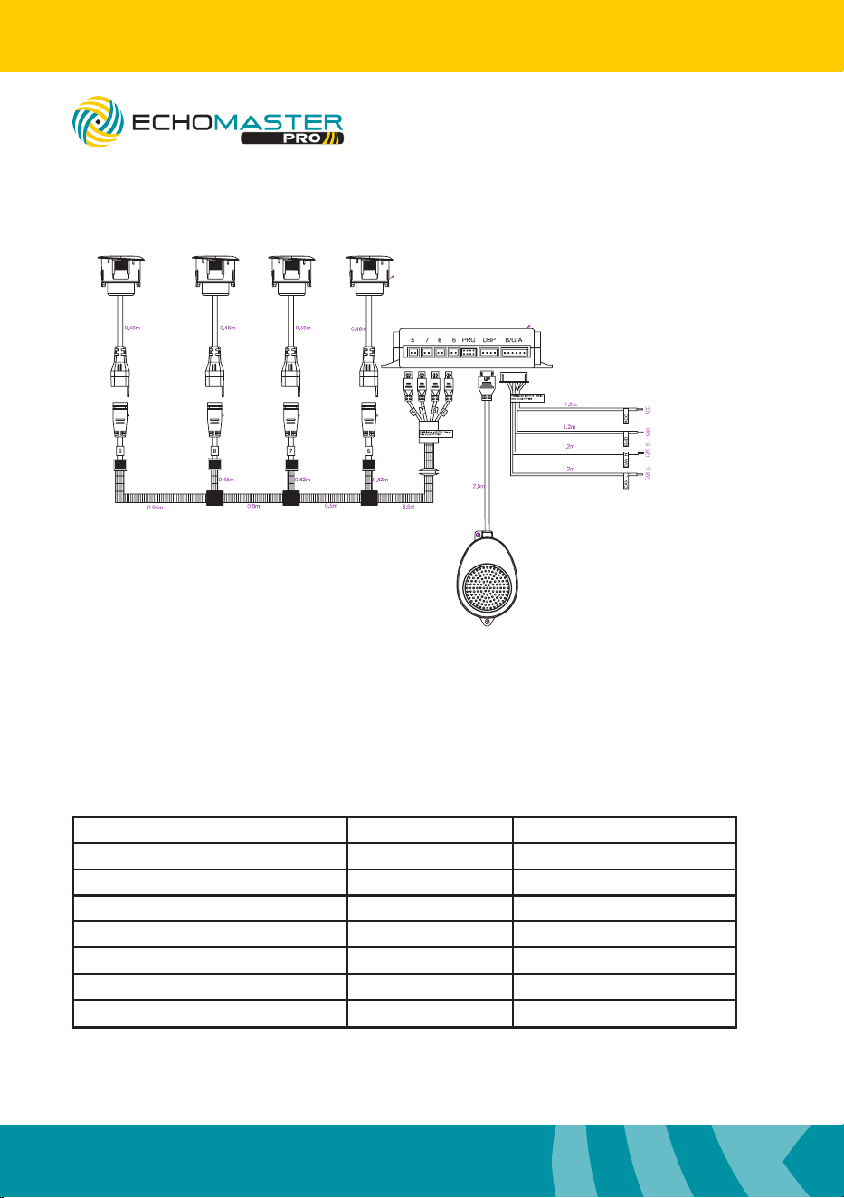
Wiring Diagram
Operating Guide
This system is fully automatic. It is on when the vehicle ignition is on. It is active when
the speed is below 6 mph and is in standby mode when above 10 mph. The system
should beep one time when powered on to notify the driver that it is on and working.
Once an object is detected within the range, the system will alert the driver via audible
tone. The system will stop beeping after ~2 seconds if there is no additional
movement detected. The detection range and audible alerts are as follows:
NOTE:
If using optional display (PA-DISPLAY) connect
to control module in place of speaker
Distance Visual Awareness Display/Alarm Sound
<12”/ <0.3m Danger -P- (STOP)/Beep (Biiiiiiiiiiiiiiiiiii)
12” – 16”/ 0.3-0.4m Danger Inches/Bi. Bi
16” – 20”/ 0.4-0.5m Caution Inches/Bi.. Bi
20” – 24”/ 0.5-0.6m Caution Inches/Bi… Bi
24” – 28” / 0.6-0.7m Caution Inches/Bi…. Bi
28” – 32” / 0.7-0.8m Safety Inches/Bi….. Bi
>32” / >0.8m Outside Inches (up to 98”)/None
NOTE -Performance may be affected by the following: Heavy rain, loose gravel/bumpy road,
steep slopes, at/smooth surfaces. Keep sensor surface free of snow, ice, mud, etc.
PS-FBP/PS-FDIS
ParkAlert Front Sensor System
with Buzzer or Display
9
Installation Guide
tel - 1-800-477-2267 (East Coast) - 1-888-883-2790 (West Coast)
email - [email protected] (US)
email - [email protected] (Europe)
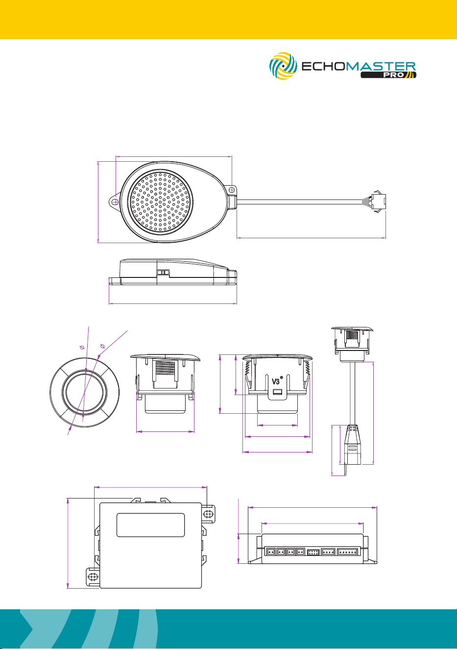
NOTE:
If using optional display (PA-DISPLAY) connect
to control module in place of speaker
5 7 8 6 DSP B/G/APRG
98mm / 3.85
77mm / 3.03
110mm / 4.33
87mm / 3.42
14.0mm / 0.55”
26.0mm / 1.0”
21.9mm / 0.9”
14.9mm / 0.6”
21.5mm / 0.8”
26mm / 1.0”
24.2mm / 0.95”
15.0mm/0.9”
460mm/18”
32mm/1.25”
25mm/0.98”
Dimensions (mm/in)
63.7mm / 2.5”
44.8mm / 1.7”
70.2 / 2.8”
2500mm / 98.4”
PS-FBP/PS-FDIS
ParkAlert Front Sensor System
with Buzzer or Display

10
Installation Guide
tel - 1-800-477-2267 (East Coast) - 1-888-883-2790 (West Coast)
email - [email protected] (US)
email - [email protected] (Europe)
PROBLEM REASON SOLUTION
System doesnt react when
reverse is engaged
System is not powered up or
wrong connection of power
cable
Check the power and
ground connections
Invalid connection between
speaker/display and control
module
Check the connection
between speaker/display
and control module
After activation, system
continuously beeps for 3
seconds
Invalid connection between
sensors and control module
Check the connection
between sensors and
control module
All sensors are defective Replace the defective
sensors
False alarms
Sensors pointing down Change angle sleeve
Sensors rotated Note ‘UP’ marking on
sensor and adjust
accordingly
Troubleshooting
Specifications
PS-FBP-B/M/W/S - PS-FDIS-B/M/W/S
Operating Voltage Range 10.5 - 16V DC
Rated Voltage 12V DC
Rated Current 400mA
Operating Temperature -20C - +70C
Waterproof Grade (Sensors & Module) IP67 - ECU: IP40
Detection Range 0-1.6m; 0-5.2ft
Harness Length 8 feet
Hole Saw 22.5mm
Angle Sleeves 6 degrees and 12 degrees
PS-FBP/PS-FDIS
ParkAlert Front Sensor System
with Buzzer or Display

11
Installation Guide
tel - 1-800-477-2267 (East Coast) - 1-888-883-2790 (West Coast)
email - [email protected] (US)
email - [email protected] (Europe)
PS-FBP/PS-FDIS
ParkAlert Front Sensor System
with Buzzer or Display

email - [email protected] (US)
tel - 1-800-477-2267 (East Coast) - 1-888-883-2790 (West Coast)
email - [email protected] (Europe)
15500 Lightwave Drive, Suite 202, Clearwater, Florida 33760
EchoMaster is a Power Brand of AAMP Global.
EchoMaster.com
REV 071524