About notation
Preface
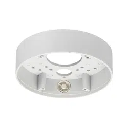
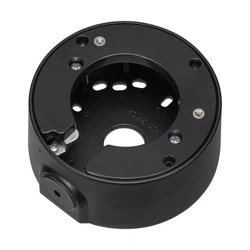
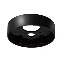
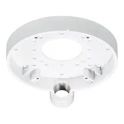
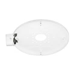
Mount the camera onto the installation surface using this bracket.
Use this bracket when conduits are used for wiring, or when there is no space available for wiring in
the installation surface.
For the latest information about the supported cameras and brackets, refer to our
technical information
website <Control No.: C0501>.
Specifications
Ambient operating temperature: –50 °C to +60 °C {–58 °F to 140 °F}
Dimensions:
ø300 mm × 15 mm (H) {ø11-13/16 inches × 19/32 inches (H)}
(excluding
conduit base and conduit cover
)
Mass: Approx. 790
g
{1.74 lbs}
Finish: Surface treatment steel sheet
W
Precautions for installation
In order to prevent injury, the product must be securely mounted to the installation
surface according to the Operating Instructions.
Screw tightening
Do not use an impact driver. Use of an impact driver may damage the screws or cause tightening excessively.
Make sure to remove this product if it will no longer be used.
Standard accessories
Operating Instructions (this document) ....................................................................................... 1 pc.
Fixing screws for attachment plate (M4 × 8 mm {5/16 inches}) .................................................. 5 pcs.
(of them, 1 for spare)
Cable cover B ............................................................................................................................ 1 pc.
Conduit base
*1
........................................................................................................................... 1 pc.
Conduit cover ............................................................................................................................ 1 pc.
Template B ................................................................................................................................ 1 pc.
*1 The female thread for conduit is compliant with ANSI NPSM (parallel pipe threads) 3/4 or
ISO228-1 (parallel pipe threads) G3/4.
Other items that are needed (not included)
Precautions
Do not use this product except with suitable cameras.
Failure to observe this may cause a drop resulting in injury.
Refer installation work to the dealer.
Installation work requires technique and experiences.
Failure to observe this may cause fire, electric shock, injury, or damage to the product.
Be sure to consult the dealer.
The screws and bolts must be tightened to the specified torque.
Failure to observe this may cause a drop resulting in injury or accidents.
Install the p roduct securely on an installati on surface in accordance with the
installation instructions.
Failure to observe this may cause injury or accidents.
Do not rub the edges of metal parts with your hand.
Strong rubbing may cause injury.
When using this product, also read the “Precautions” described in the operating instruc-
tions for the camera to be attached.
Operating Instructions
Included Installation Instructions
Base Bracket
Model No.
WV-QJB503
•
Before attempting to connect or install this product, please read these instructions carefully and
save this manual for future use.
• The external appearance and other parts shown in this manual may differ from the actual
product within the scope that will not interfere with normal use due to improvement of the
product.
i-PRO Co., Ltd. assumes no responsibility for injuries or property damage resulting
from failures arising out of improper installation or operation inconsistent with this
documentation.
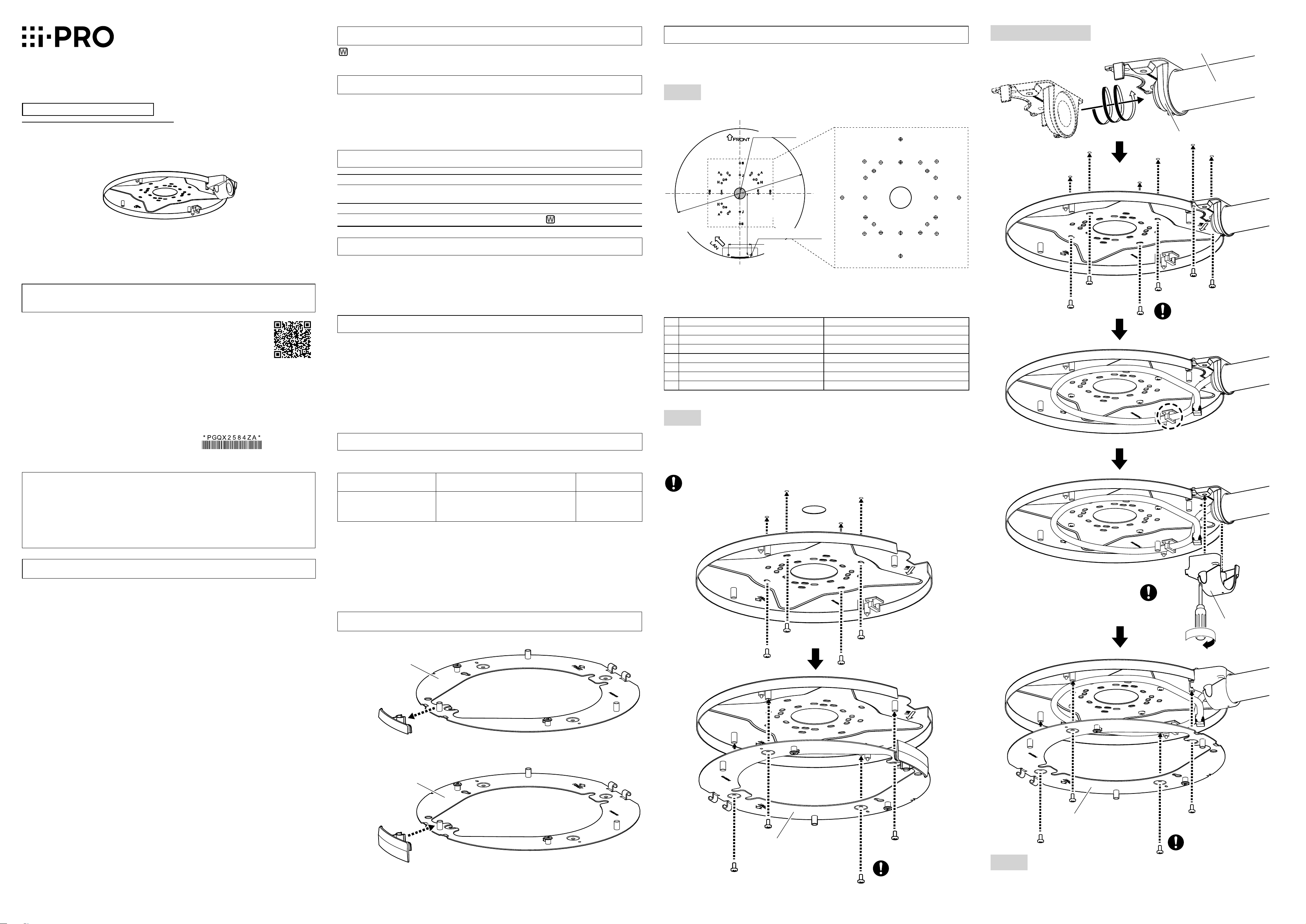
Installation
Be sure to read "Precautions" and "Precautions for installation" before installation.
Refer to the operating instructions of the camera or the bracket for details including the
camera or bracket mounting, their adjustment and the cable connection.
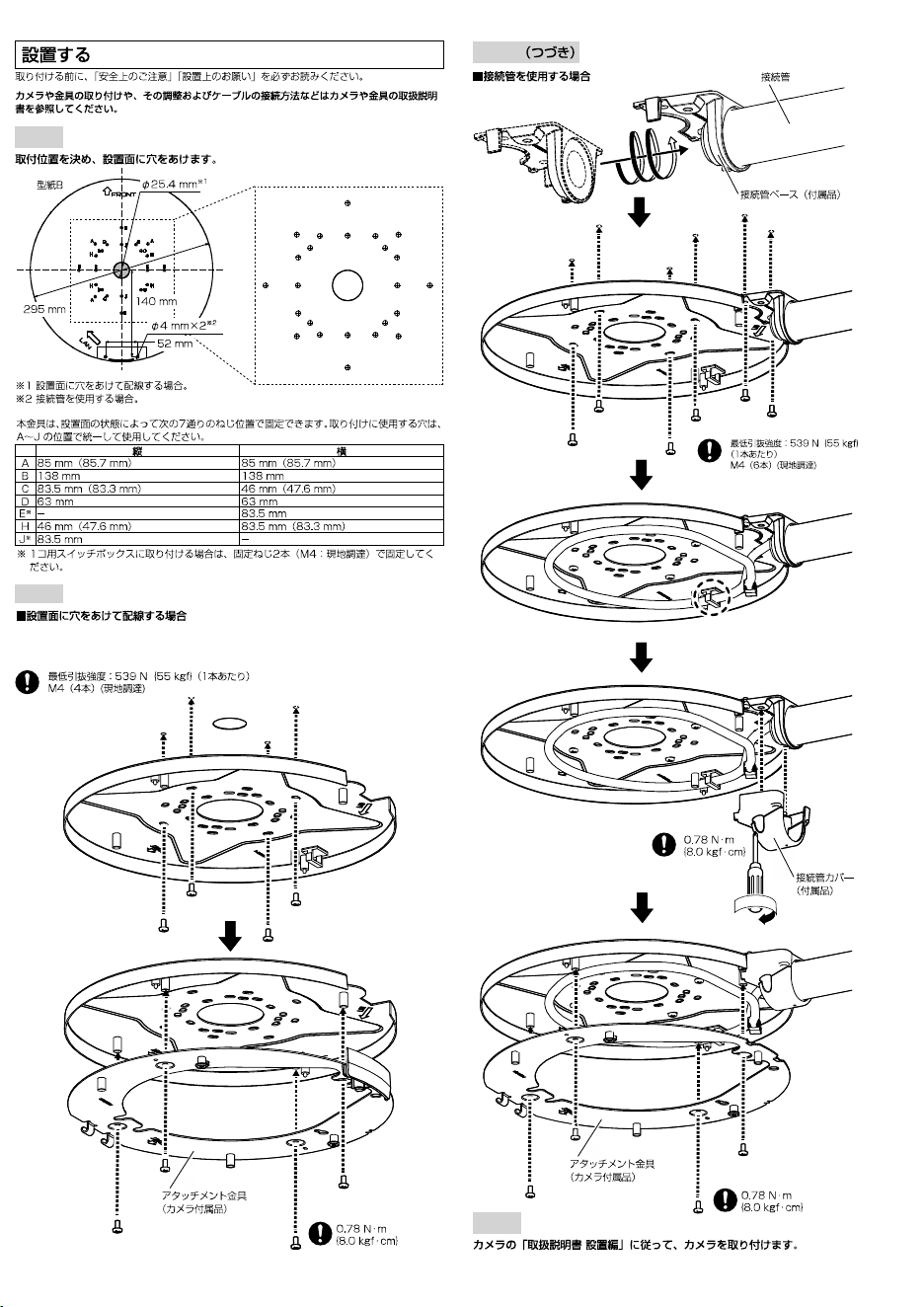
Step 1
Decide the mounting position and then drill holes in the
nstallation surface
.
* 1 When drilling a hole through the installation surface.
* 2 When using the conduit
Caution:
• Before attempting to connect or operate this
product, please read these instructions care-
fully.
Notice:
• This product is not suitable for use in loca-
tions where children are likely to be present.
• Do not install this product in locations where
ordinary persons can easily reach.
• For information about screws and other
parts required for installation, refer to the
corresponding section of this document.
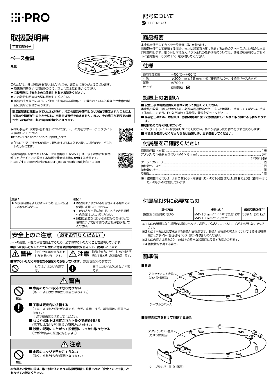
Preparations
© i-PRO Co., Ltd. 2022
avs0322-0
Printed in China
For U.S. and Canada:
i-PRO Americas Inc.
For Europe and other countries:
i-PRO EMEA B.V.
https://www.i-pro.com/
"<Control No.: C****>" used in these documents should be used to search for information
on our technical information website (https://i-pro.com/global/en/surveillance/training-
support/support/technical-information) and will guide you to the right information.
Installation method Recommended screw
*1
Minimum pull-out
strength
*2
Directly mount the camera onto
the installation surface using
the attachment plate
M4 × 16 mm {5/8inches}*
3
× 4pcs. or 2pcs.
M4 × 16 mm {5/8inches}*
3
× 2pcs.*
4
539 N {121 lbf}
*1 Select screws according to the material of the location that the camera will be mounted to. In this
case, wood screws and nails should not be used.
*2 This value indicates the minimum pull-out strength required value per screw. For information
about the minimum pull-out strength, refer to our technical information website <Control No.:
C0120>.
*3 The screw length is an example when installing the camera on a robust installation surface with a
thickness of 20mm {25/32inches} or more.
*4 When using the conduit.
Attachment plate
(accessory of the
camera)
Cable cover A
Common
When drilling a hole through the installation surface
Attachment plate
(accessory of the
camera)
Cable cover B
(accessory)
Template B
H
H
AA
C
C
C
C
H H
A
A
D
D
D
D
B
B
B
B
J
J
E
E
295 mm
{11-5/8 inches}
ø
25.4 mm
*1
{
ø
1 inch}
ø4 mm
*2
{5/32 inches}
52 mm
{1-1/16 inch
es}
140 mm
{5-1/2 inches}
Depending on the condition of the installation surface, the following seven patterns of screw
positions are available for fixation of the this bracket. Use only the holes of the same pattern (A - J)
for mounting.
Vertical Horizontal
A
85 mm {3-11/32 inches}(85.7 mm {3-3/8 inches}) 85 mm {3-11/32 inches}(85.7 mm {3-3/8 inches})
B
138 mm {5-7/16 inches} 138 mm {5-7/16 inches}
C
83.5 mm {3-9/32 inches} (83.3 mm {3-9/32 inches}) 46 mm {1-13/16 inches} (47.6 mm {1-7/8 inches})
D 63 mm {2-15/32 inches} 63 mm {2-15/32 inches}
E* – 83.5 mm {3-9/32 inches}
H
46 mm {1-13/16 inches} (47.6 mm {1-7/8 inches}) 83.5 mm {3-9/32 inches} (83.3 mm {3-9/32 inches})
J* 83.5 mm {3-9/32 inches} –
* When mounting to a single-gang junction box, fix with two fixing screws (M4: locally procured).
Step 2
When drilling a hole through the installation surface
Step 4
Install the camera by following the Installation Guide of the camera.
Minimum pull-out strength: 539 N {121 lbf} (per 1 pc.)
M4 (4 pcs.) (locally procured)
0.78 N·m
{0.58 lbf·ft}
0.78 N·m
{0.58 lbf·ft}
Conduit
When using the conduit
Conduit base (accessory)
Conduit cover
(accessory)
Attachment plate
(accessory of the
camera)
0.78 N·m
{0.58 lbf·ft}
Step 2 (Continued)
Minimum pull-out strength:
539 N {121 lbf} (per 1 pc.)
M4 (6 pcs.) (locally procured)
Attachment plate
(accessory of the
camera)
: i-PRO white
W
About notation
Preface
Mount the camera onto the installation surface using this bracket.
Use this bracket when conduits are used for wiring, or when there is no space available for wiring in
the installation surface.
For the latest information about the supported cameras and brackets, refer to our
technical information
website <Control No.: C0501>.
Specifications
Ambient operating temperature: –50 °C to +60 °C {–58 °F to 140 °F}
Dimensions:
ø300 mm × 15 mm (H) {ø11-13/16 inches × 19/32 inches (H)}
(excluding
conduit base and conduit cover
)
Mass: Approx. 790
g
{1.74 lbs}
Finish: Surface treatment steel sheet
W
Precautions for installation
In order to prevent injury, the product must be securely mounted to the installation
surface according to the Operating Instructions.
Screw tightening
Do not use an impact driver. Use of an impact driver may damage the screws or cause tightening excessively.
Make sure to remove this product if it will no longer be used.
Standard accessories
Operating Instructions (this document) ....................................................................................... 1 pc.
Fixing screws for attachment plate (M4 × 8 mm {5/16 inches}) .................................................. 5 pcs.
(of them, 1 for spare)
Cable cover B ............................................................................................................................ 1 pc.
Conduit base
*1
........................................................................................................................... 1 pc.
Conduit cover ............................................................................................................................ 1 pc.
Template B ................................................................................................................................ 1 pc.
*1 The female thread for conduit is compliant with ANSI NPSM (parallel pipe threads) 3/4 or
ISO228-1 (parallel pipe threads) G3/4.
Other items that are needed (not included)
Precautions
Do not use this product except with suitable cameras.
Failure to observe this may cause a drop resulting in injury.
Refer installation work to the dealer.
Installation work requires technique and experiences.
Failure to observe this may cause fire, electric shock, injury, or damage to the product.
Be sure to consult the dealer.
The screws and bolts must be tightened to the specified torque.
Failure to observe this may cause a drop resulting in injury or accidents.
Install the p roduct securely on an installati on surface in accordance with the
installation instructions.
Failure to observe this may cause injury or accidents.
Do not rub the edges of metal parts with your hand.
Strong rubbing may cause injury.
When using this product, also read the “Precautions” described in the operating instruc-
tions for the camera to be attached.
Operating Instructions
Included Installation Instructions
Base Bracket
Model No.
WV-QJB503
•
Before attempting to connect or install this product, please read these instructions carefully and
save this manual for future use.
• The external appearance and other parts shown in this manual may differ from the actual
product within the scope that will not interfere with normal use due to improvement of the
product.
i-PRO Co., Ltd. assumes no responsibility for injuries or property damage resulting
from failures arising out of improper installation or operation inconsistent with this
documentation.
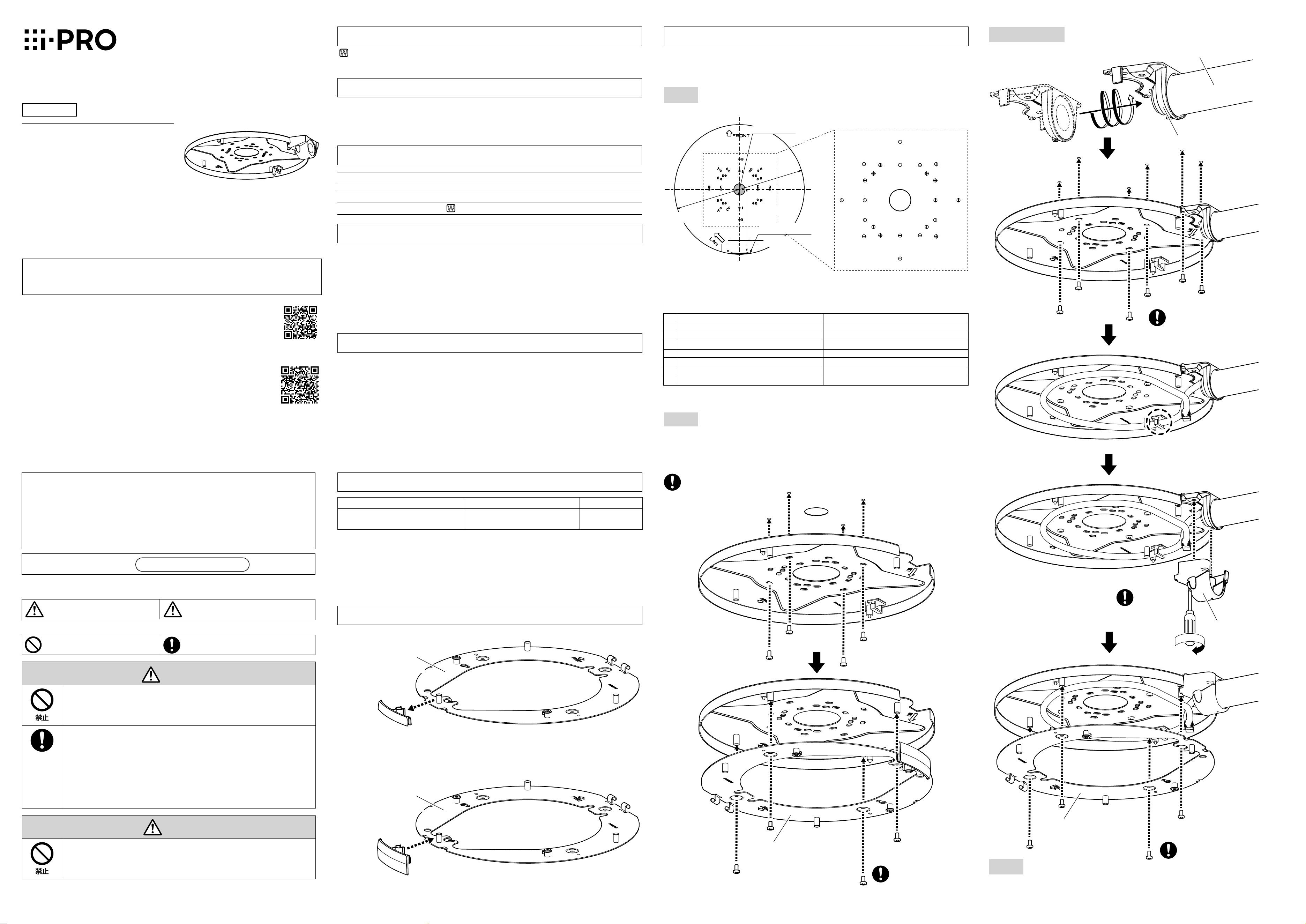
Installation
Be sure to read "Precautions" and "Precautions for installation" before installation.
Refer to the operating instructions of the camera or the bracket for details including the
camera or bracket mounting, their adjustment and the cable connection.
Step 1
Decide the mounting position and then drill holes in the
nstallation surface
.
* 1 When drilling a hole through the installation surface.
* 2 When using the conduit
Caution:
• Before attempting to connect or operate this
product, please read these instructions care-
fully.
Notice:
• This product is not suitable for use in loca-
tions where children are likely to be present.
• Do not install this product in locations where
ordinary persons can easily reach.
• For information about screws and other
parts required for installation, refer to the
corresponding section of this document.
Preparations
© i-PRO Co., Ltd. 2022
avs0322-0
Printed in China
For U.S. and Canada:
i-PRO Americas Inc.
For Europe and other countries:
i-PRO EMEA B.V.
https://www.i-pro.com/
"<Control No.: C****>" used in these documents should be used to search for information
on our technical information website (https://i-pro.com/global/en/surveillance/training-
support/support/technical-information) and will guide you to the right information.
Installation method Recommended screw
*1
Minimum pull-out
strength
*2
Directly mount the camera onto
the installation surface using
the attachment plate
M4 × 16 mm {5/8inches}*
3
× 4pcs. or 2pcs.
M4 × 16 mm {5/8inches}*
3
× 2pcs.*
4
539 N {121 lbf}
*1 Select screws according to the material of the location that the camera will be mounted to. In this
case, wood screws and nails should not be used.
*2 This value indicates the minimum pull-out strength required value per screw. For information
about the minimum pull-out strength, refer to our technical information website <Control No.:
C0120>.
*3 The screw length is an example when installing the camera on a robust installation surface with a
thickness of 20mm {25/32inches} or more.
*4 When using the conduit.
Attachment plate
(accessory of the
camera)
Cable cover A
Common
When drilling a hole through the installation surface
Attachment plate
(accessory of the
camera)
Cable cover B
(accessory)
Template B
H
H
AA
C
C
C
C
H H
A
A
D
D
D
D
B
B
B
B
J
J
E
E
295 mm
{11-5/8 inches}
ø
25.4 mm
*1
{
ø
1 inch}
ø4 mm
*2
{5/32 inches}
52 mm
{1-1/16 inch
es}
140 mm
{5-1/2 inches}
Depending on the condition of the installation surface, the following seven patterns of screw
positions are available for fixation of the this bracket. Use only the holes of the same pattern (A - J)
for mounting.
Vertical Horizontal
A
85 mm {3-11/32 inches}(85.7 mm {3-3/8 inches}) 85 mm {3-11/32 inches}(85.7 mm {3-3/8 inches})
B
138 mm {5-7/16 inches} 138 mm {5-7/16 inches}
C
83.5 mm {3-9/32 inches} (83.3 mm {3-9/32 inches}) 46 mm {1-13/16 inches} (47.6 mm {1-7/8 inches})
D 63 mm {2-15/32 inches} 63 mm {2-15/32 inches}
E* – 83.5 mm {3-9/32 inches}
H
46 mm {1-13/16 inches} (47.6 mm {1-7/8 inches}) 83.5 mm {3-9/32 inches} (83.3 mm {3-9/32 inches})
J* 83.5 mm {3-9/32 inches} –
* When mounting to a single-gang junction box, fix with two fixing screws (M4: locally procured).
Step 2
When drilling a hole through the installation surface
Step 4
Install the camera by following the Installation Guide of the camera.
Minimum pull-out strength: 539 N {121 lbf} (per 1 pc.)
M4 (4 pcs.) (locally procured)
0.78 N·m
{0.58 lbf·ft}
0.78 N·m
{0.58 lbf·ft}
Conduit
When using the conduit
Conduit base (accessory)
Conduit cover
(accessory)
Attachment plate
(accessory of the
camera)
0.78 N·m
{0.58 lbf·ft}
Step 2 (Continued)
Minimum pull-out strength:
539 N {121 lbf} (per 1 pc.)
M4 (6 pcs.) (locally procured)
Attachment plate
(accessory of the
camera)
: i-PRO white
W
W
WV-QJB503
Step1
H
H
AA
C
C
C
C
H H
A
A
D
D
D
D
B
B
B
B
J
J
E
E
Step2
Step3
https://www.i-pro.com/
Step2
W
W
WV-QJB503
Step1
H
H
AA
C
C
C
C
H H
A
A
D
D
D
D
B
B
B
B
J
J
E
E
Step2
Step3
https://www.i-pro.com/
Step2
W