Loading ...
Loading ...
Loading ...
9
G1 I1
H1
J1
K1
2x
ST 3.2*13mm
1X
ST 4.2*12mm
2X
ST 4.2*6.5mm
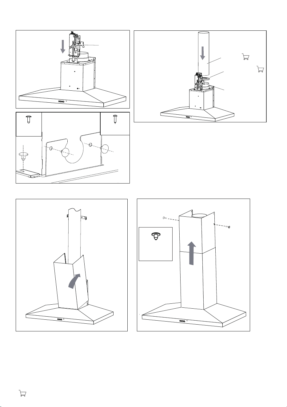
Diagram G1
• Insert the clip of power box into product
Diagram H1
• Fasten the power box with the screws supplied to ensure
the power box is securely fastened.
Diagram I1
• Loosen the hose clamp and put it outside of Duct
transition
• Fit the flue over the outer wall of Duct transition
• Tighten the hose clamp with a screwdriver to secure to
Duct transition.
Diagram J1
• Install bottom section of telescopic flue
cover.
Diagram K1
• Install top section of telescopic flue cover
and fasten the cover with supplied screws.
Flue
Hose clamp
Duct transition
Power box
*
*
:sourced locally
Loading ...
Loading ...
Loading ...