Loading ...
Loading ...
Loading ...
8
Recommended installation sequence
External exhaust mode installation
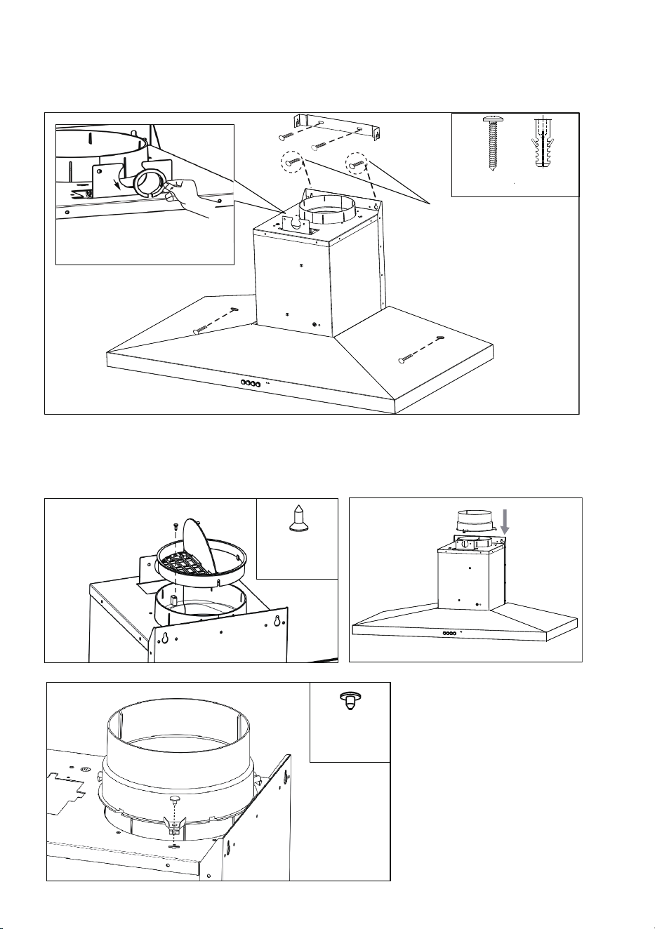
C1
6X
WOOD SCREWS Ø4*30
WALL PLUG Ø6
Diagram C1
• Install cooker hood body. Determine working height, mark wall to suit. Install flue cover mounting
brackets.
• Ensure the screws highlighted in “C1” have 3mm gap between screw head and wall, this will ensure
suffcient space for body fitment.
D1
E1
F1
1X
ST 4.2*6.5mm
1X
ST 2.9*9.5mm
Diagram D1
• Fit the non-return valve to the outlet of
the range hood.
• Fasten the non-return valve with the
screw supplied to ensure the non-return
valve is securely fastened.
Diagram E1
• Insert the three clips of Duct transition
into product
Diagram F1
• Fasten the Duct transition with the
screw supplied to ensure the Duct
transition is securely fastened.
* Leave 3mm gap between
screw head and wall
Take the ring off before installing, it
is for transportation only and may
be disposed of.
Loading ...
Loading ...
Loading ...