0
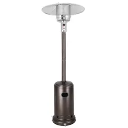
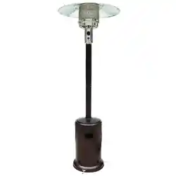
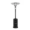
OUTDOOR PATIO HEATER
FOR OUTDOOR USE ONLY !
PLEASE KEEP THE MANUAL FOR FUTURE USE.
THE INSTALLER OR SELLER MUST LEAVE THE MANUAL TO THE CONSUMER.
INSTRUCTION MANUAL

1
TABLE OF CONTENTS
Warnings 1-3
Assembly 3
Gas Requirements & Connecting To A Gas Cylinder 4
Securing A Gas Cylinder 4
Minimum Clearance from Combustible Materials 5
Gas Leak testing 5
Lighting Instructions 6
Safe Appliance Locations 6-7
Maintenance & Servicing 8
Storage 8
Trouble Shooting 9
Technical Data 10
WARNINGS
For outdoor use only !
For propane gas use only.
Improper installation, adjustment, alteration, service or maintenance can cause injury or property damage.
Read the instructions thoroughly before installing or servicing this appliance.
For your safety, if you smell gas:
Shut off the gas to the appliance.
Extinguish any open flame.
If odor continues, immediately call your gas supplier.
Do not store or use gasoline or other flammable vapor and liquids in the vicinity of this or any other appliance.
This appliance must only be used in a well ventilated area.
This appliance shall not be installed or used indoors, in buildings, garages or any other enclosed area.
Do not place articles on or against this appliance.
Do not use or store flammable materials near this appliance.
Never hang anything including clothes or other flammable items on the appliance.
Do not operate this appliance unless it is fully assembled with burner guard in place.
Any guard or other protective device removed for servicing the appliance must be replaced prior to
operating the appliance.
Do not spray aerosols in the vicinity of this appliance while it is in operation.
Children and adults should be alerted to the hazards of high surface temperatures burns and clothing
ignition.
Young children should be carefully supervised when they are in the area of the appliance
Repair should be done by a qualified service person. The appliance must be inspected before use and at
least annually by a qualified service person. It is imperative that control compartment, burners and
circulating air passages of the heater be kept clean.
Prior to assembling your appliance, the following must be reviewed. Compliance with the following should result
in satisfactory heater operation. The installation must conform with local codes or authority have jurisdiction.
The appliance is intended for heating residential and non residential outdoor spaces. The installation must
conform with local codes or in the absence of local codes, with the Australian Standard AS/NZS5601.1:2013.
Adequate clearance around air opening into the combustion chamber, clearances from combustible materials,
provisions for accessibility and for the combustions and ventilating air supply must be maintained at all times
when the appliance is operating.

2
Combustible materials are considered to be wood, compressed paper, plant fibers, plastic, plexiglas or other
materials capable of being ignited and burned. Such materials shall be considered combustible even though
flame proofed, fire retardant treated or plastered. Additional clearance may be required for glass, painted
surfaces and other materials which may be damaged by radiant or convention heat.
Heater must be placed on a level and adequate footing and be readily accessible.
The gas manifold supply pressure must be regulated at 2.75kPa utilizing an AGA approved regulator.
The appliance must be kept clear and free of combustible materials, gasoline and other flammable vapors and
liquids.
Gas orifices and burner must be kept clear of dirt and cobwebs. Flow of combustion and ventilation air through
the perforated portions of the heater must not be obstructed. Cleaning with a soft brush before use and at least
every six months is recommended.
All gas connections should be checked for leaks utilizing a soap solution. Never use a flame for this purpose.
The flame pattern at the emitter grid should be visually checked whenever heater is operated. If flames extend
beyond surface of the emitter grid or black spot is accumulating on the emitter grid or reflector, the heater should
be turned off immediately. The heater should not be operated again until the heater is serviced and or repaired.
Any cleaning agent used on the heater should be of a noncombustible and non corrosive nature.
The stainless steel emitter grid normally does not require cleaning and should never be painted.
The hose assembly should be located out of pathways where people may trip over it. The hose must be
protected from contact with hot or sharp surfaces both during use and while in storage. The hose assembly
should be visually inspected prior to each use of the heater. If excessive abrasion or wear is evident, or the hose
is cut, it must be replaced prior to operating the heater. The replacement hose assembly may be obtained from
the manufacture.
Do not use any pressure regulator or hose assembly other than those supplied with the appliance. Replacement
pressure regulator and hose assembly must be those specified. Replacement parts may be obtained from the
manufacture or your local dealer.
Installation and use of this heater must conform with local codes or in the absence of local codes, with the
Standards of Storage and Handling of Liquefied Petroleum Gases.
This heater is designed to operate with a 9kg propane cylinder with approved cylinder connection.
The valve outlet must be maintained in good condition. When the cylinder is not in use, be sure to cover it with a
dust cap. A leak test should be performed with soapy water whenever the connecting a new cylinder. Never use
a match to test for leaks.
The propane cylinder must be turned off whenever the heater is not in use. When the heater is to be stored
indoors, the propane cylinder and the heater must be disconnected and the cylinder stored in accordance with
the Standard for Storage and Handling of Liquefied Gases.
The heater has been designed with several safety features which include a tip over switch.
Storage of an appliance indoors with the cylinder attached is only permitted if the size of the cylinder complies
with AS/NZS 1596, otherwise cylinders must be stored outdoors in a well ventilated area.
The guards are fitted to the appliance to reduce the risk of fire or injury from burns and no part of it should be
removed.
The appliance must be protected from exposure to rain.
Any modification to the heater not described in the installation instructions may be compromise the safety of this
appliance. Special concerns are as follows:
Do not bypass the thermocouple safety burner.
Do not operate the heater without the guard.
Clothing or other flammable materials should not be hung from the heater, or placed on or near the
heater. The area above the burner may be extremely hot. Direct contact with these metal surfaces
should be avoided in order to prevent burns or clothing ignition.
3
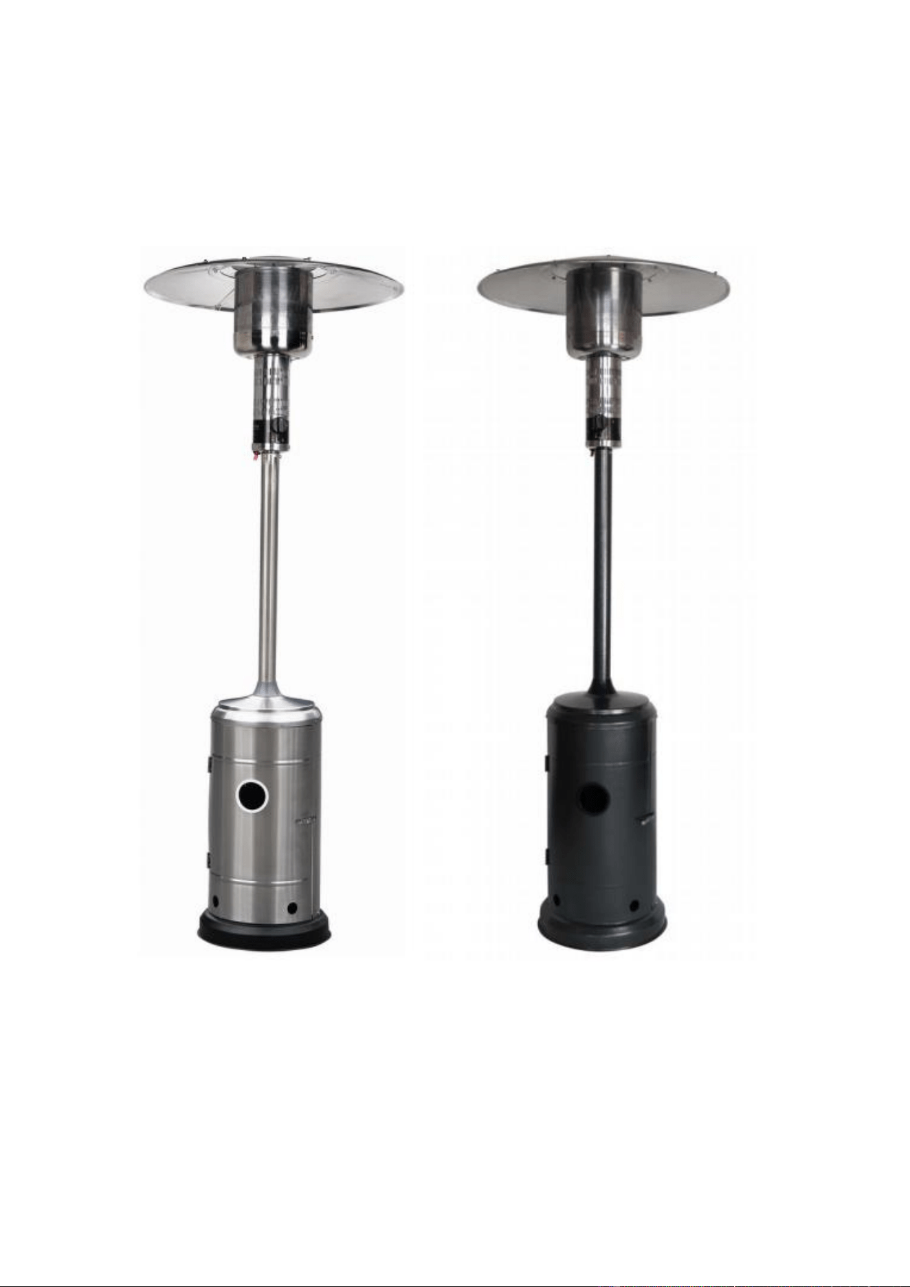
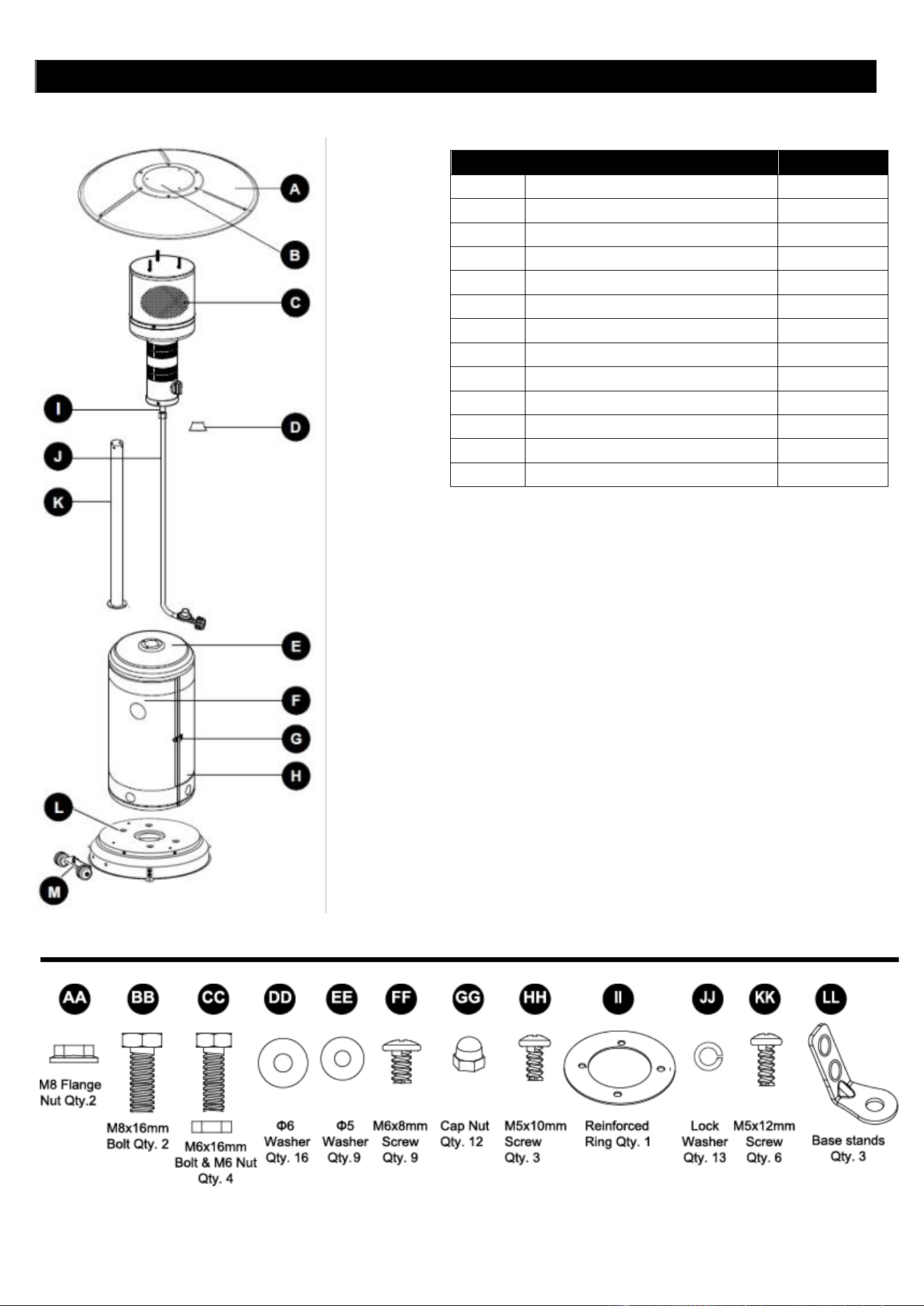
PART LIST
ALL HARDWARE CONTENTS (Include preassembled)
PART
DESCRIPTION
QUANTITY
A
Reflector Panel
3
B
Reflector Plate
1
C
Head Assembly
1
D
Deck Ring
1
E
Top of Housing (preassembled)
1
F
Door (preassembled)
1
G
Door Lock (preassembled)
1
H
Rear of Housing (preassembled)
1
I
Gas Pipe
1
J
Hose & Regulator
1
K
Post
1
L
Base (preassembled)
1
M
Wheel Kit
1
4
ASSEMBLY
Instruction before assembly
Required Tools: Philip Screwdriver / Adjustable Spanners / Wrenches
Leak Detection Solution: one part detergent and three parts water
Assemble all nuts and bolts loosely at first. Tighten all connections after completion of assembly. This eases your
work and increases the stability of your appliance.
Before assembly, make sure all packing material and any transmit protection must be moved.
Small deviations in equipment may occur. This is no lack of quality but subject to improvements.
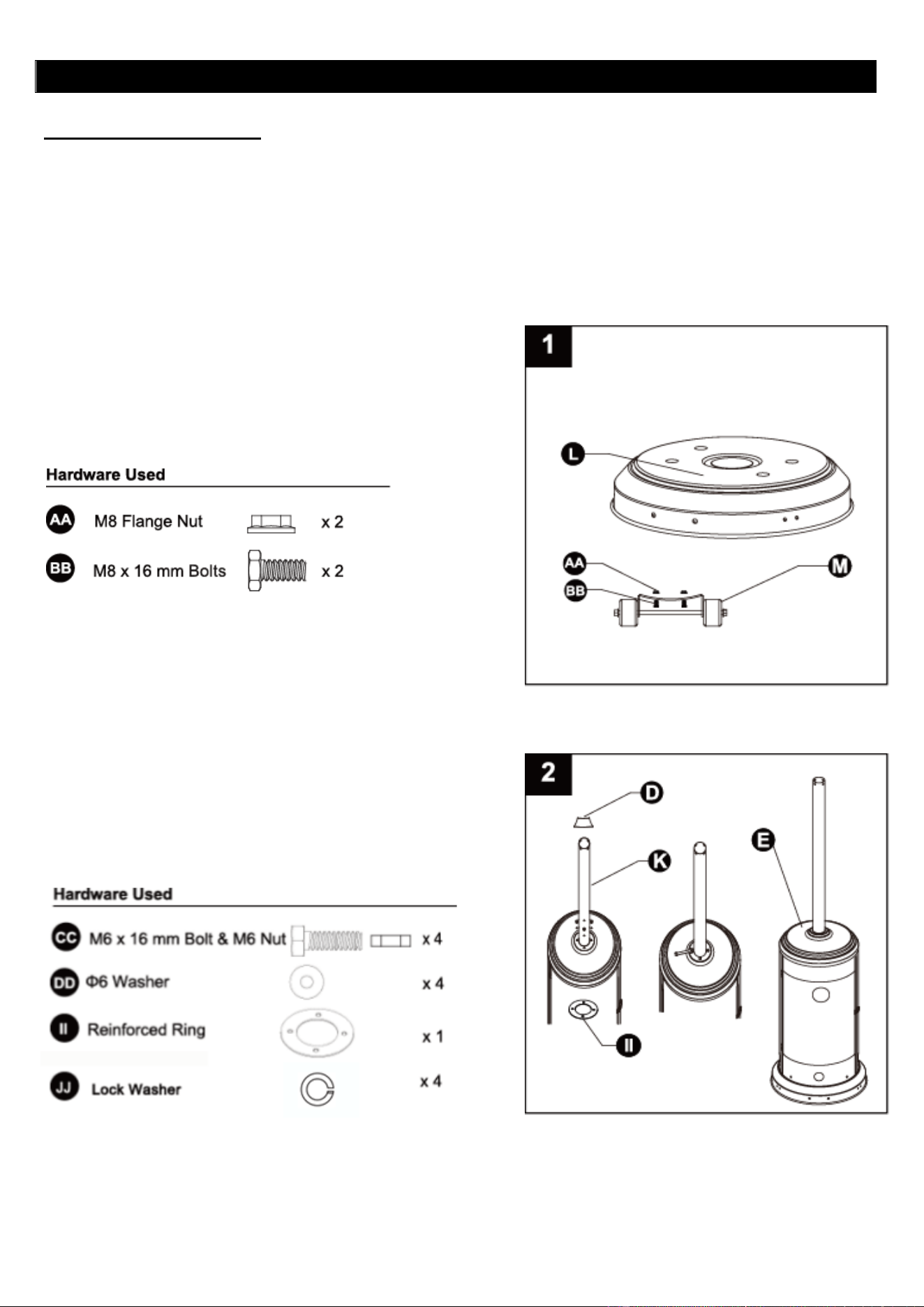
1. Line up holes on the bracket of wheel assembly (M) with the
corresponding holes on base (L), then insert M8 x 16 mm
bolts (BB) through holes. Hand tighten with M8 flange nuts
(AA). Be sure the wheel assembly (M) is parallel to the base
(L).
2. Put post (K) on the top of housing (E), put reinforced ring (II)
under top of housing (E).Secure post (K) and reinforced ring (II)
using M6 x 16 mm Bolt and M6 Nut (CC), lock washer(JJ), Φ6
Washers (DD). Fasten and cover with the deck ring (D).
5
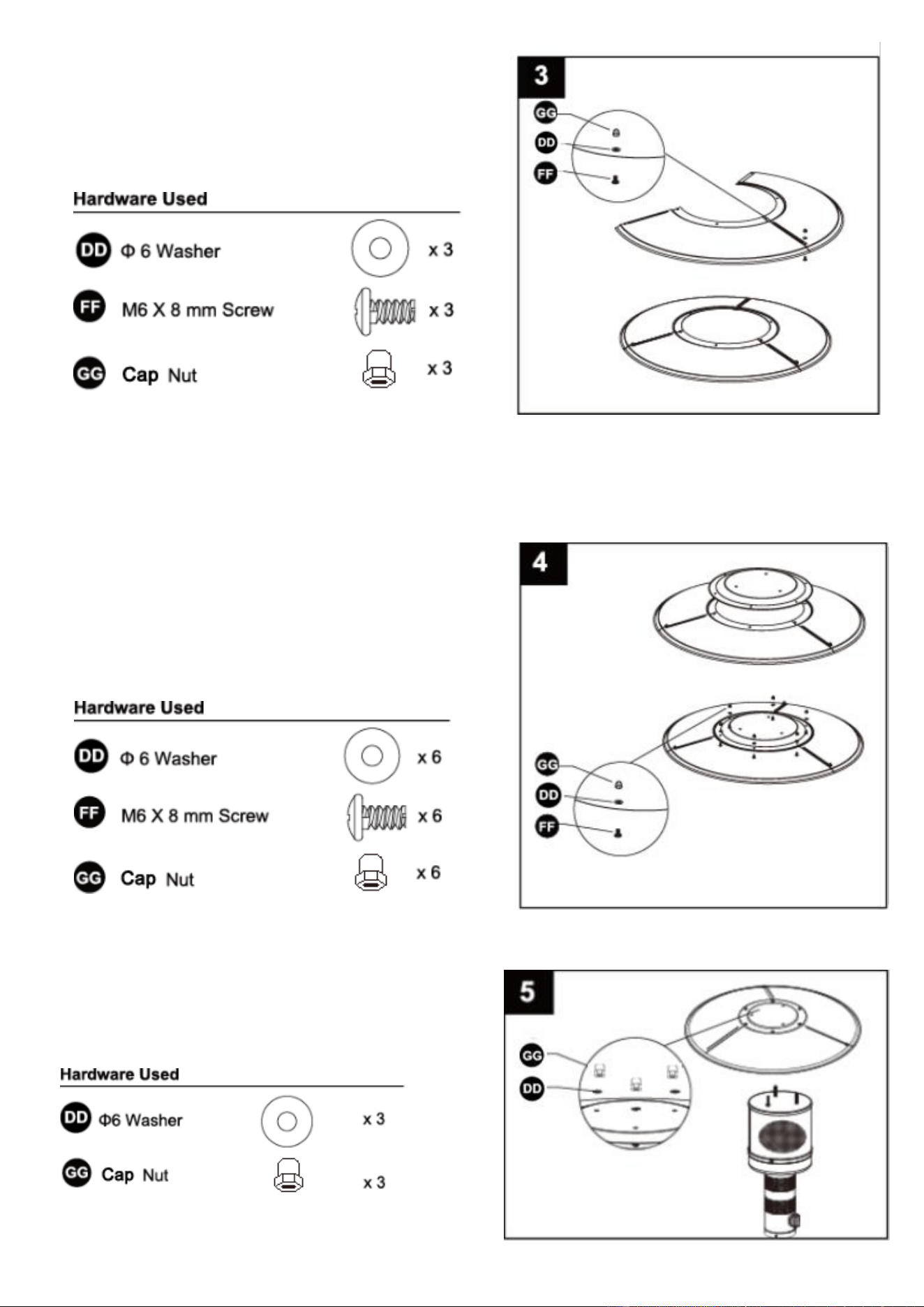
3. Attach reflector panels (A) together using M6 x 8mm
screws
(FF), Φ6 washers (DD) and cap nuts (GG).
Secure loosely with cap nuts (GG).
Note: In order to achieve proper alignment of reflector sections,
it may be necessary to loosen the preassembled bolts prior to
assembly and retighten once complete.
4. Attach reflector plate (B) to reflector panels (A) using M6 x
8mm screws (FF), Φ6 washers (DD) and cap nuts (GG).
Secure loosely with cap nuts (GG).
Note: Once properly aligned, tighten all screws and
the preassembled bolts.
5. Attach reflector assembly to head assembly (C).
Secure with cap nuts (GG) and Φ6 washers (DD).
Note: Do not over tighten!
6
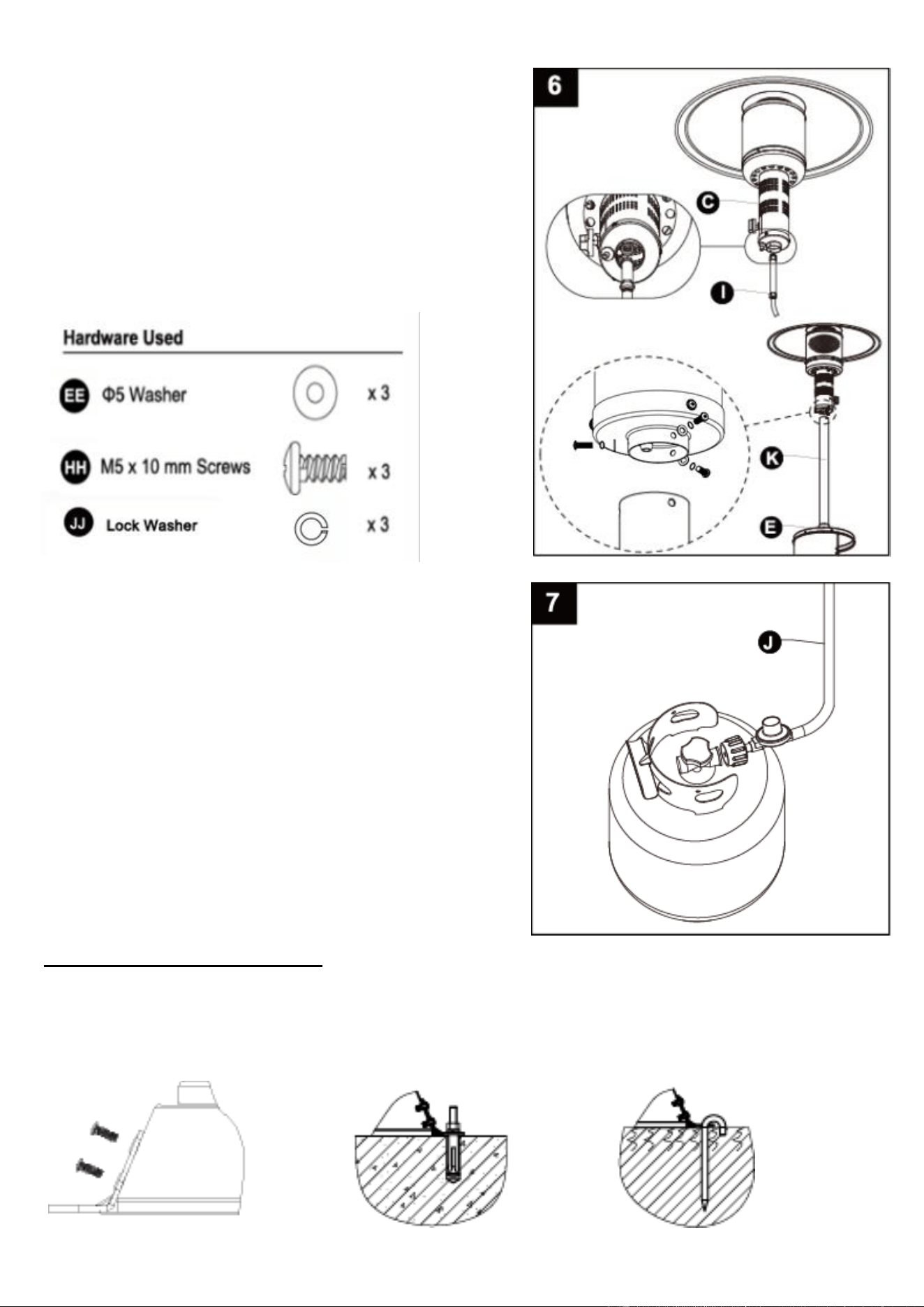
6. Insert gas pipe with hose & regulator assembly (I/J) through top
of housing (E) and Post (K), tighten gas pipe (I) to head
assembly(C).
Secure head assembly (C) to the post (K) using preassembled
bolts M5 x 10 (HH), lock washer (JJ), and Φ5 washers (EE).
Note: The control knob on head assembly (C) should be
aligned with door (F).
The pressure regulator and hose assembly to be used must
conform to local standard codes.
7. Secure gas hose and regulator (J) onto gas cylinder (not
included).
Place the gas cylinder into the rear of housing (H), then close the
door (F).
Note: See instruction Gas requirement and Connecting to a
gas cylinder before buying a gas cylinder.
Optional base stands assembly
Secure 3pcs base stands to the base using preassembled 6pcs bolts M5 x 12 (KK), 6pcs Φ5 washers (EE) and 6pcs
lock washers (JJ) firstly, then strike suitable hook bolts or rawlbolts from local market through the stand holes into the
ground or floor. (See figure 1)
7
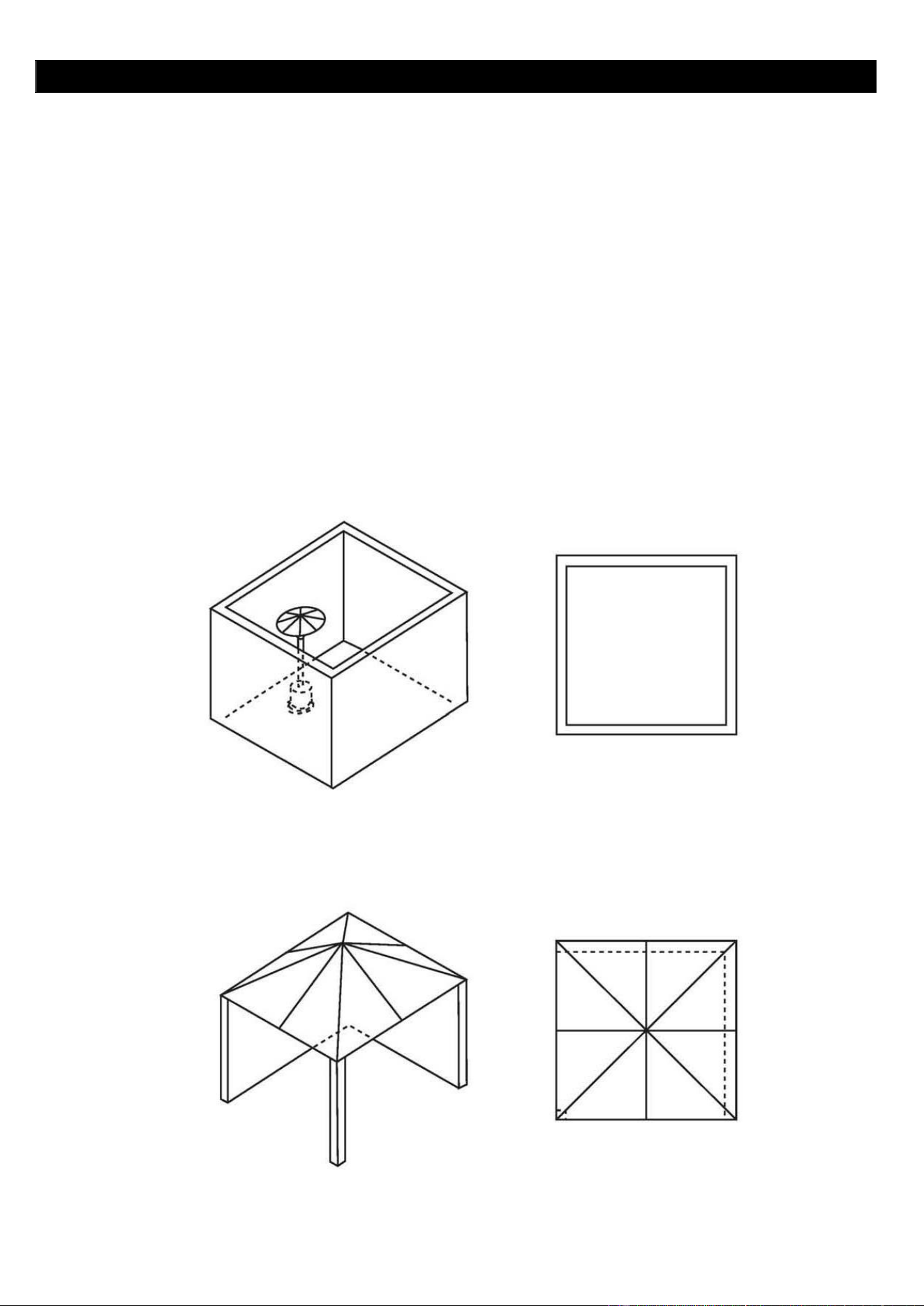
SAFE APPLIANCE LOCATIONS
This appliance shall only be used in an above ground open air situation with natural ventilation,
without stagnant areas, where gas leakage and products of combustion are rapidly dispersed by wind
or natural convection.
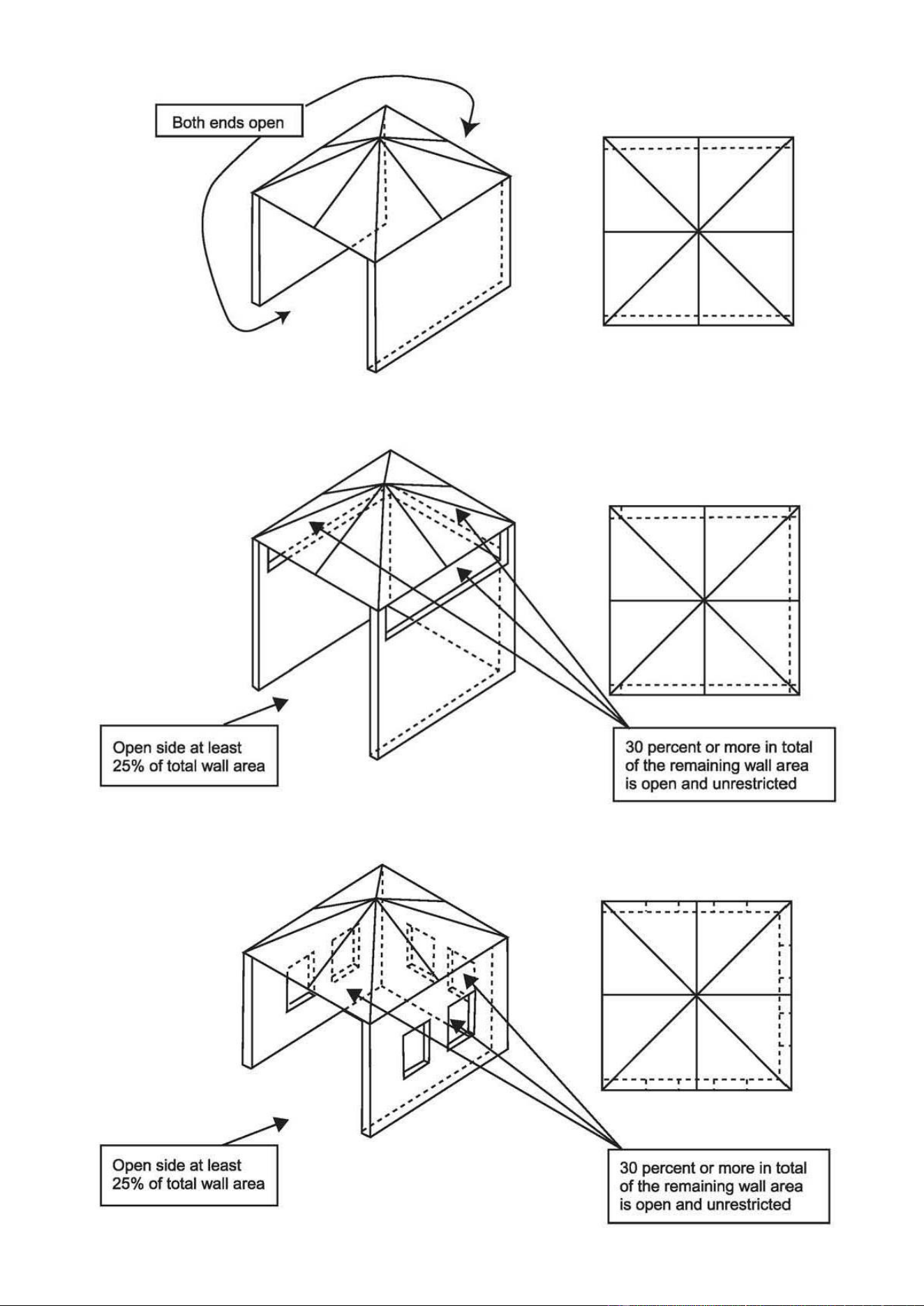
Any enclosure in which the appliance is used shall comply with one of the following:
An enclosure with walls on all sides, but at least one permanent opening at ground level and no overhead
cover.
With a partial enclosure that includes an overhead cover and no more than two walls.
With a partial enclosure that includes an overhead cover and more than two walls, the following will apply:
At least 25% of the total wall area is completely open, and
At least 30% of the remaining wall area is open and unrestricted.
In the case of balconies, at least 20% of the total wall area shall be and remain open and unrestricted.
The following figures are diagrammatical representations of outdoor areas. Rectangular areas have been used
in these figures-the same principles apply to any other shaped areas.
8
9
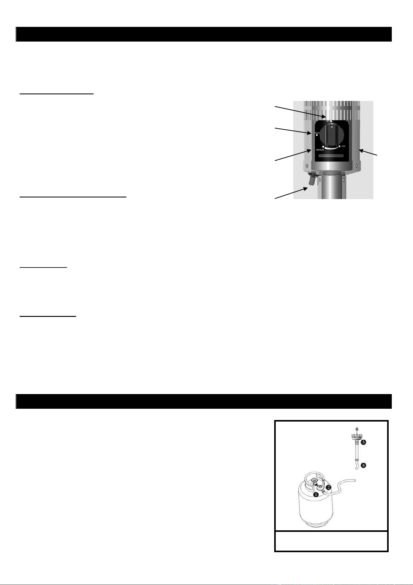
Leak Test Point ① ② ③ ④
OPERATING INSTRUCTIONS
BEFORE FIRST USE AND AFTER EVERY GAS CYLINDER CHANGE, GAS DELIVERY SYSTEM MUST BE
PURGED OF AIR BEFORE IGNITING! TO DO THIS, TURN THE CONTROL KNOB ANTI-CLOCKWISE TO THE
PILOT SETTING. PRESS KNOB IN AND HOLD FOR 3 MINUTES BEFORE ATTEMPTING IGNITION.
TO LIGHT THE PILOT
TO LIGHT THE PATIO HEATER
The pilot should be lit and the knob set to PILOT.
Hold knob depressed gently and turn anti-clockwise to HIGH.
When mesh glows lit, turn knob from HIGH to LOW as needed.
Note: The burner may be noisy when initially turned on. To eliminate excessive noise from the burner, turn
the control knob to the pilot position. Then turn the knob to the level of heat desired.
RE-LIGHTING
Turn Control Knob to OFF.
Wait at least 5 minutes, to let gas dissipate, before attempting to re-light pilot.
Repeat the “Lighting” steps.
TO EXTINGUISH
Hold knob depressed & turn the knob clockwise to 'OFF'
Close the valve of the gas cylinder or the regulator after use.
Close the gas bottle and allow this appliance to cool before moving.
Note: After use, some discoloration of the emitter screen is normal. Close regulator after use, allow the
appliance to cool before moving.
LEAK TESTING
NEVER USE A NAKED FLAME TO CHECK FOR LEAKS.
NEVER LEAK TEST WHILE SMOKING.
The gas connections on this appliance are leak tested at the factory prior to
shipment.
This appliance needs to be periodically checked for leaks and an immediate
check is required if the smell of gas is detected.
Make a soap solution using 1 part of liquid dish-washing soap to 3 parts
water. The soap solution can be applied with a soap bottle, brush, or rag
to the leak tested points shown in the figure right.
The valve of the gas cylinder should be in the OFF position at this point
of the leak test. Once the soapy solution is applied to the gas
connections, the valve of the gas cylinder needs to be turned to the ON
position.
PILOT
IGNITION
OFF
HIGH
LOW
Check all connections prior to each use.
Turn on main gas supply at source.
Press to turn control knob anti-clockwise to PILOT, see right photo.
Hold knob depressed, press IGNITION button repeatedly until pilot
flame is lit, then continue to hold the knob depressed for 10
seconds until the pilot remains it after releasing knob.
If pilot fails to ignite or alight, press to turn knob clockwise to OFF
and repeat.
10
Soap bubbles will begin to form in the soapy solution if a leak is present.
In case of a leak, turn off the gas supply. Tighten any leaking fittings, then turn the gas supply on and recheck.
In case of any damage or gas leakage after several attempts, contact your local dealer for assistance.
GAS REQUIREMENTS
The pressure regulator and hose assembly to be used must conform to local standard codes.
Never use a gas cylinder with a damaged body, valve, collar, or foot ring. A dented or rusty gas tank may be
hazardous and should be checked out by a gas supplier.
Never connect this appliance to an unregulated gas source.
When the appliance is not in use, turn the gas cylinder OFF.
Always perform a leak test on gas connections whenever a cylinder is connected. If bubbles form in the leak test
solution, do not use. Never use a flame to test for leaks.
CONNECTING TO A GAS CYLINDER
Use 9 kg gas cylinder. Please refer to your gas supplier for suitable gas cylinder.
Refer to your gas supplier for instructions on the use of your gas cylinder.
Only change gas cylinders outdoors or in a well ventilated area away from naked flames and any other source of
ignition.
The gas cylinder must always be used in an upright position.
Close the heater control knob by turning fully clockwise.
Close the gas cylinder tap and then attach the regulator onto the gas cylinder.
Tighten all connections firmly and with a spanner where appropriate. The cylinder should be located on the
cylinder base.
Check for leaks at all joints using soapy water. If a leak is found, tighten the joint and then re-test.
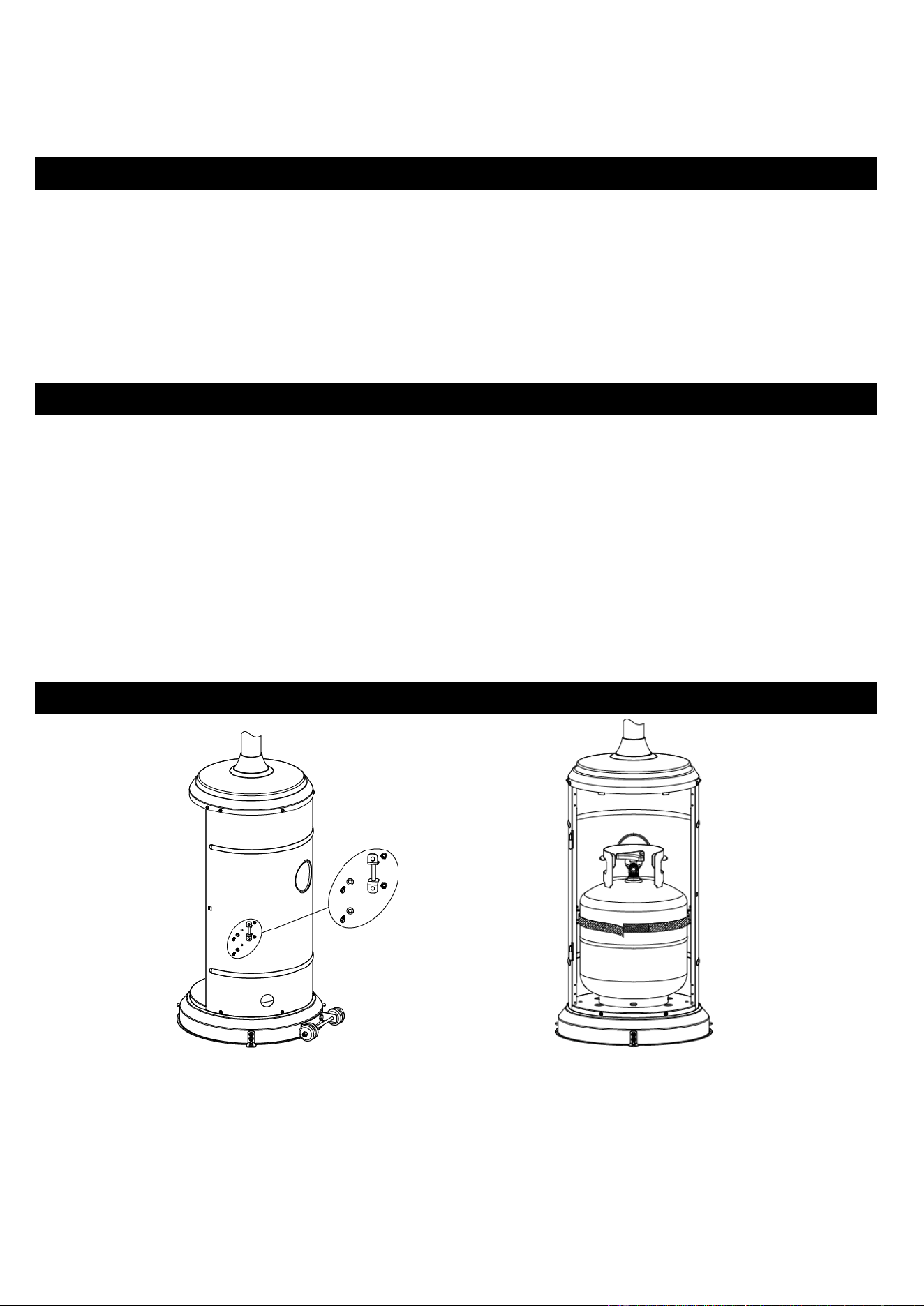
SECURING A GAS CYLINDER (OPTIONAL)
1. Fix both velcro tapes onto the rear tank housing using 4pcs M5*12 bolts with M5 washer and M5 nuts.
2. Position a gas cylinder inside the tank housing.
3. Connect the gas cylinder with a regulator. Please refer to the instructions attached with the regulator on how to
connect a regulator with the gas cylinder.
4. Stick velcro tapes together as above photo illustrated. The tapes must be in a proper tightness for the gas
cylinder.
Caution: Please take care that the velcro tapes. DO NOT strain the regulator assembly.
11
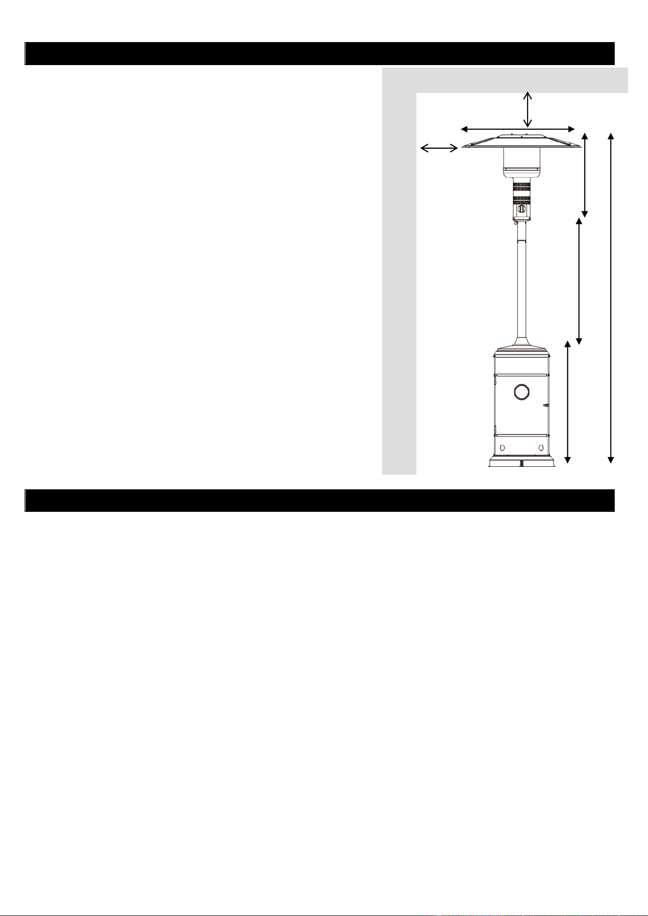
Dia.815mm
915mm
915mm
IMPORTANT SAFETY RULES
For use outdoors or in amply ventilated areas.
An amply ventilated area must have a minimum of 25% of the
surface area open.
The surface area is the sum of the walls surface.
The use of this appliance in enclosed areas can be dangerous and
is PROHIBITED.
Children and adults should be aware of the high operating
temperatures of areas above the post when operating this heater.
Children should be carefully supervised when in the vicinity of the
heater.
NEVER hang anything, including clothes or any other flammable
items, on this heater.
DO NOT operate this heater unless it is fully assembled with its
reflector in place.
Respect the minimum clearances from combustible materials.
MAINTENANCE
To enjoy years of outstanding performance from your heater, make sure you perform the following maintenance
activities on a regular basis:
Keep exterior surfaces clean.
Use warm soapy water for cleaning. Never use flammable or corrosive cleaning agents.
While washing your unit, be sure to keep the area around the burner and pilot assembly dry at all times. If the
gas control is exposed to water in any way, DO NOT try to use it. It must be replaced.
Airflow must be unobstructed. Keep controls, burner and circulation air passageways clean. Signs of possible
blockage include:
Gas odor with extreme yellow tipping of flame.
Heater does NOT reach the desired temperature.
Heater glow is excessively uneven.
Heater makes popping noises.
Spiders and insects can nest in burner or orifices. This dangerous condition can damage the heater and render
it unsafe for use. Clean burner holes by using a heavy duty pipe cleaner. Compressed air may help clear away
smaller particles.
Carbon deposits may create a fire hazard. If any carbon deposits develop, clean dome and engine with warm
soapy water.
Note: in a salt-air environment (such as near the sea), corrosion occurs more quickly than normal.
Frequently check the corroded areas and repair them promptly.
595mmm
830mm
825mm
2250mm
Ceiling/Overhang
Wall
12
SERVICING
Please consult your local dealer for servicing this appliance and replacement of its parts. The servicing of the
appliance shall be carried out only by authorised personnel.
Caution: do not use unauthorized parts or components for this appliance, only use original equipment
replacement parts and components. The use of unauthorized parts or components will void the warranty and
can create an unsafe condition.
STORAGE
There is no limitation on the storage of the appliance indoors provided that the cylinder is removed from the
appliance.
Between uses:
Turn control knob OFF
Turn gas cylinder OFF
Store heater upright in an area sheltered from direct contact with inclement weather (such as rain, sleet, hail, snow,
dust and debris).
If desired, cover to protect exterior surfaces and to prevent build up in air passages.
Note: Wait until heater is cool before covering.
During periods of extended inactivity or when transporting:
Turn control knob OFF.
Disconnect gas cylinder and move to a secure, well ventilated location outdoors. DO NOT store in a location that
will exceed 50°C.
Store heater upright in an area sheltered from direct contact with inclement weather (such as rain, sleet, hail, snow,
dust and debris).
If desired, cover heater to protect exterior surfaces and to prevent build up in air passages.
Note: Wait until heater is cool before covering
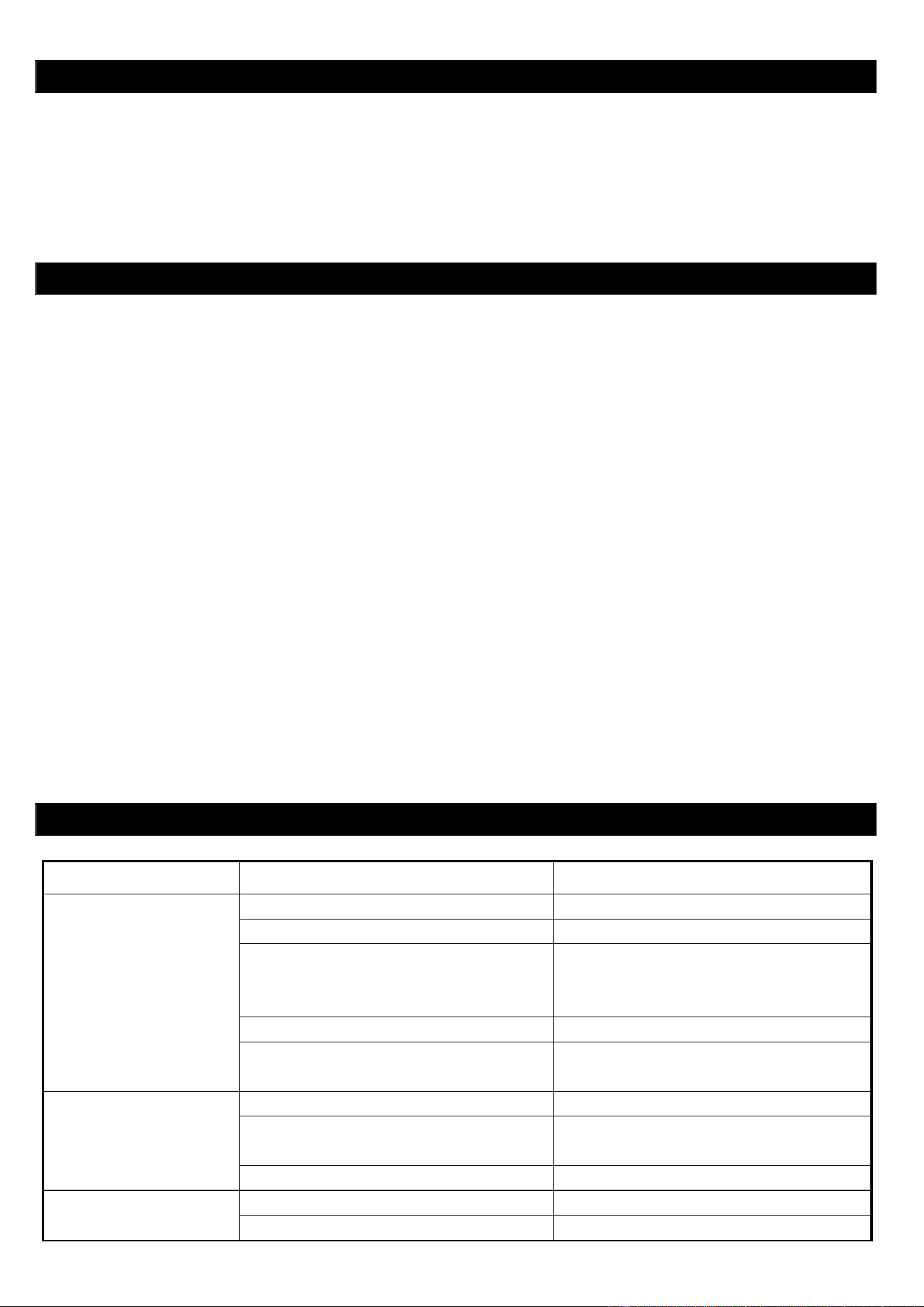
TROUBLE SHOOTING
IF THE PROBLEM IS:
AND THIS CONDITION EXISTS:
THEN DO THIS:
Pilot won’t light
Cylinder valve is closed
Open valve
Blockage in orifice or pilot tube
Clean or replace orifice or pilot tube
Air in the gas line
Open gas line and bleed it (pressing
control knob in) for not more than
1-2 minutes or until you smell gas
Low gas pressure
Gas cylinder low or empty
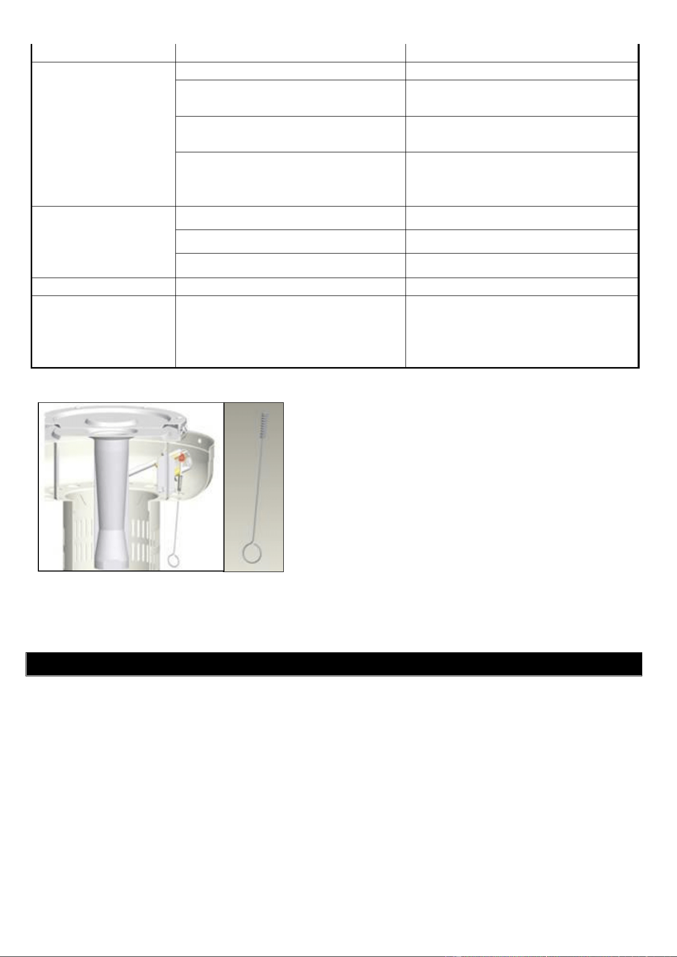
Igniter fails
Use match to light pilot, and obtain new
igniter and replace. ( See below pictures)
Pilot won’t stay lit
Dirt build up around pilot
Clean dirt from around pilot
Connection between gas valve and pilot
assembly is loose
Tighten connection and perform leak test
Bad thermocouple
Replace thermocouple
Burner won’t light
Gas pressure is low
Replace gas cylinder
Blockage in orifice
Clear blockage
13
Control knob is not in "ON" position
Turn control knob to "ON" position
Burner flame is low
Note: Do not operate
heater below 5
℃
(40°F)
Gas pressure is low
Replace gas cylinder
Outdoor temperature is greater than 5℃
(40°F) and tank is less than 25% full
Replace gas cylinder
Supply hose is bent or kinked
Straighten hose and perform leak test on
hose
Control knob is fully " ON"
Turn control knob to "OFF", let it cool to
room temperature and check burner and
orifices for blockage
Emitter glows uneven
Note: Bottom 2.5cm of
emitter normally does
not normally glow
Gas pressure is low
Replace gas cylinder
Base is not on a level surface
Place heater on a level surface
Heater not level
Level heater
Carbon build-up
Dirt or film on reflector and emitter
Clean reflector and emitter
Thick black smoke
Blockage in burner
Turn control knob to "OFF", let it cool to
room temperature and remove
blockage and clean burner inside and
outside.
IN THE EVENT OF ANY PROBLEM, PLEASE ALWAYS CONSULT YOUR LOCAL DEALER.
TECHNICAL DATA
Model number: H1107G & H1207G
Gas type: propane
Nominal GC: 40.5MJ/h
By-pass GC: 20.00MJ/h
Test point pressure: 2.75kPa
Injector size: 1.80mm
AGA cert. no.: AGA 7004 G
If for some reasons your ignition fails to deliver a spark, the heater
can be started by inserting a lit match using supplied match holder
through the burner hole (see left photo) while pushing the control
knob in the “PILOT” position.