Loading ...
Loading ...
Loading ...
3.Junior User Guidebook
12
Oscilloscope with CH1 Channel.
Align the slot in the probe with the plug in the CH1 connector BNC, and then
tighten the probe with rotating it to the right side.
Connect the probe tip and the ground clamp to the connector of the probe
compensator.
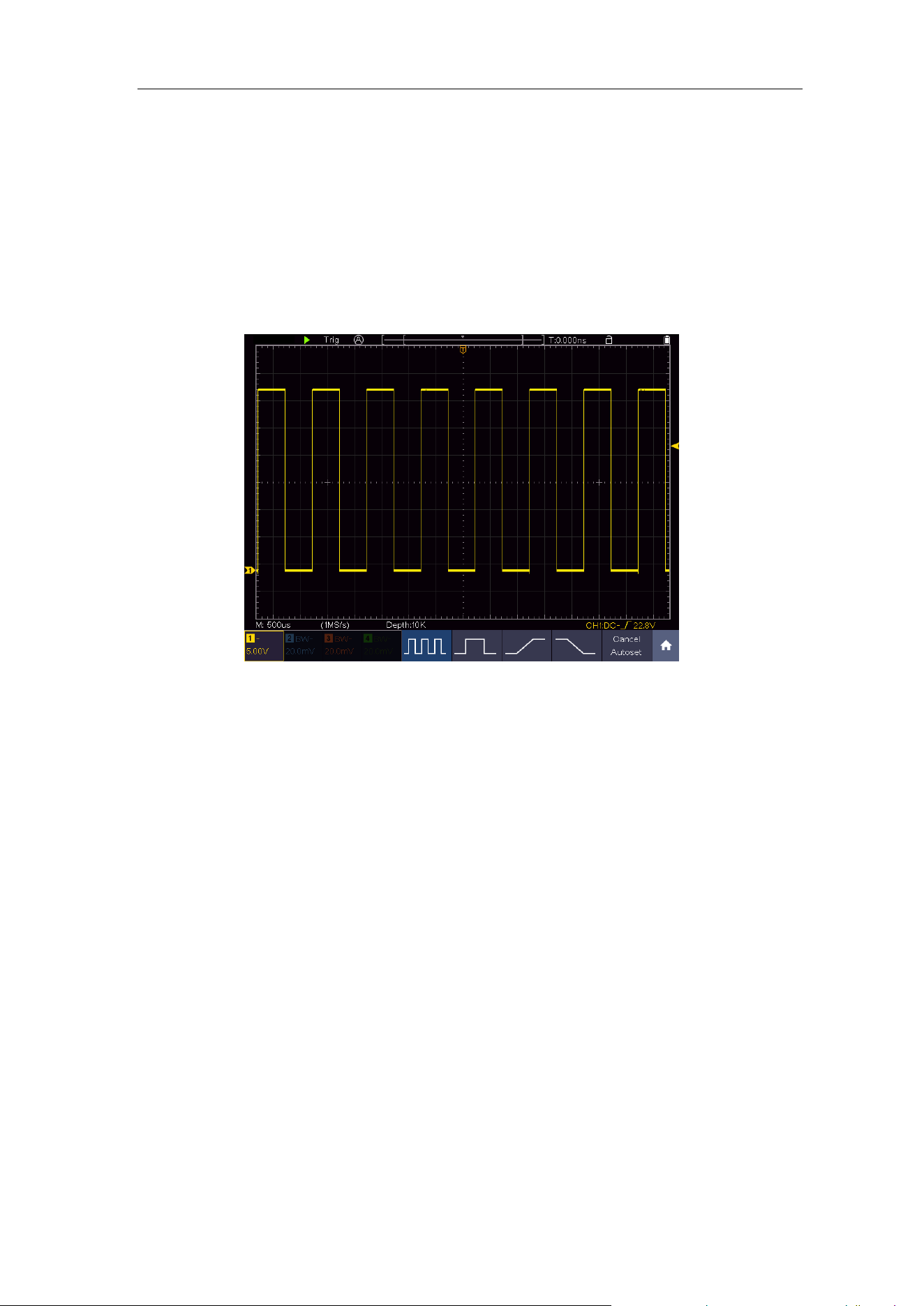
3. Push the Autoset Button on the front panel.
The square wave of 1 KHz frequency and 3.3V peak-peak value will be
displayed in several seconds (see Figure 3-5).
Figure 3-5 Auto set
Check CH2, CH3 and CH4 by repeating Step 2 and Step 3.
How to Implement the Probe Compensation
When connect the probe with any input channel for the first time, make this
adjustment to match the probe with the input channel. The probe which is not
compensated or presents a compensation deviation will result in the
measuring error or mistake. For adjusting the probe compensation, please
carry out the following steps:
1. Set the attenuation coefficient of the probe on the menu as 10X and that of
the switch in the probe as 10X (see "How to Set the Probe Attenuation
Coefficient" on P13), and connect the probe with the CH1 channel. If a
probe hook tip is used, ensure that it keeps in close touch with the probe.
Connect the probe tip with the signal connector of the probe compensator
and connect the reference wire clamp with the ground wire connector of
the probe connector, and then push the Autoset button on the front panel.
2. Check the displayed waveforms and regulate the probe till a correct
compensation is achieved (see Figure 3-6 and Figure 3-7).
Loading ...
Loading ...
Loading ...