Loading ...
Loading ...
Loading ...
41
41
26
27
69
71
69
71
67
68
68
74
75
67
1
69
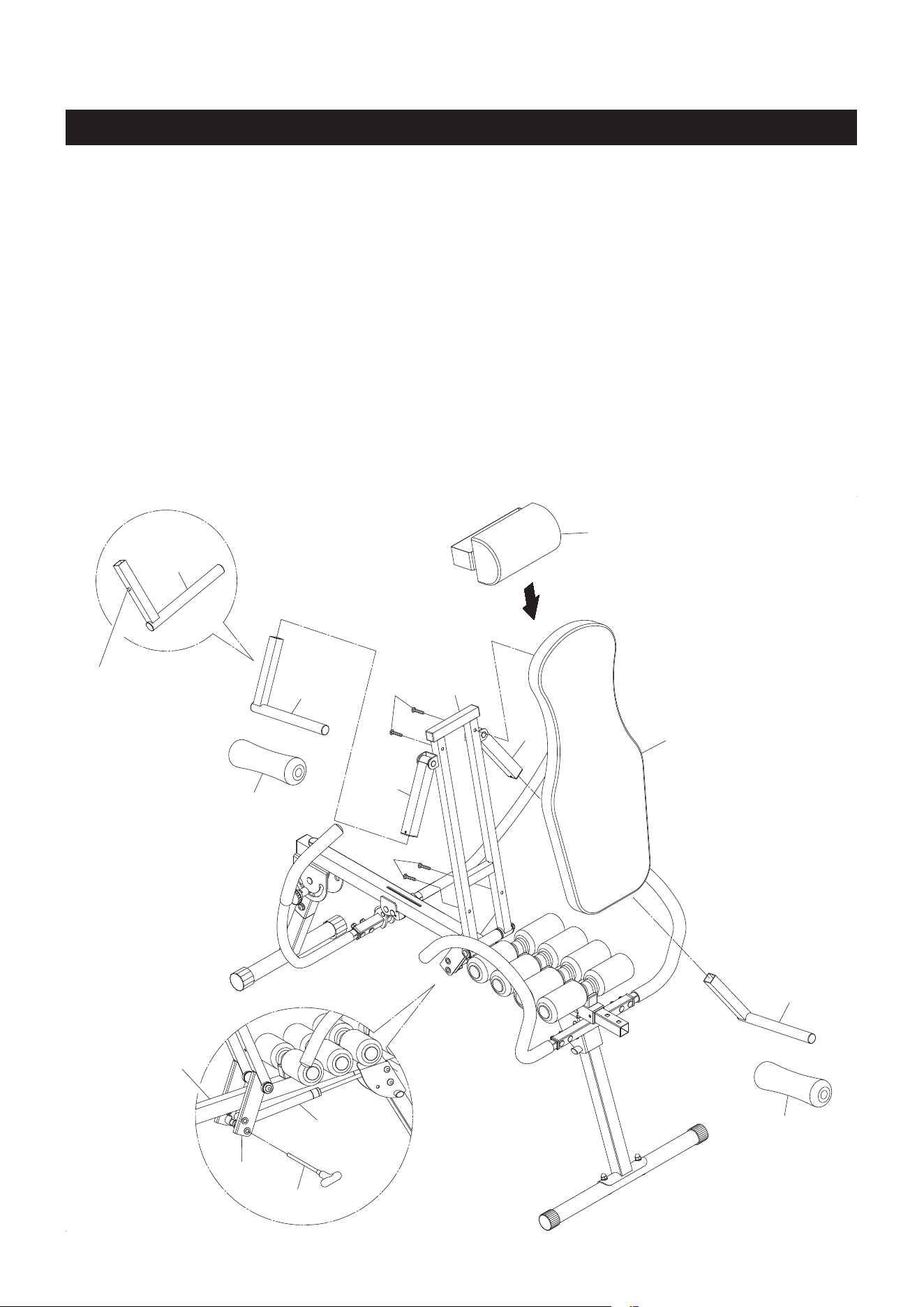
ASSEMBLY INSTRUCTIONS
10
STEP 5: Refer to detail view A and the illustration below. Swing up the CUSHION SUPPORT(67), then
place the end of the AIR SHOCK(75) into the bracket on the CUSHION SUPPORT(67) and lock in position
with the T PULL PIN(74).
NOTE: There are two adjustment holes in the CUSHION SUPPORT(67) which allow the AIR SHOCK(75)
to be attached in two dierent positions to oer dierent support force for the CUSHION(27). Select
the position which is most comfortable for you.
STEP 6: Push the BUTTON PIN(70) in and insert the ARMPIT PAD SUPPORT(69) into the SWING ARM
(68). Slide an ARMPIT PAD(71) on the ARMPIT PAD SUPPORT(69). Repeat on other side.
NOTE: There are three adjustment holes in the SWING ARM(6) which allow the ARMPIT PAD SUPPORTS
(69) to be attached in three dierent positions. Start with the center position and adjust if necessary.
STEP 7: Attach the CUSHION(27) to the CUSHION SUPPORT(67) with BUTTON HEAD BOLTS
(M6x1x35mm)(41). Slide the PILLOW(26) onto the CUSHION(27) and make the elastic band go
across the CUSHION SUPPORT(67).
A.
Button Pin(70)
B.
Loading ...
Loading ...
Loading ...