Loading ...
Loading ...
Loading ...
8 Section 2 — ASSembly & Set-Up
Tools Required
• Adjustable Wrench or Socket Set
Connecting the Battery Cables
WARNING
California PROPOSITION 65 Battery posts, terminals,
and related accessories contain lead and lead compounds,
chemicals known to the State of California to cause cancer
and reproductive harm. Wash hands after handling.
CAUTION
When attaching battery cables, always connect the
POSITIVE (Red) wire to its terminal first, followed by the
NEGATIVE (Black) wire.
For shipping reasons, both battery cables on your
equipment may have been left disconnected from
the terminals at the factory. To connect the battery
cables, proceed as follows:
NOTE: The positive battery terminal is marked Pos.
(+). The negative battery terminal is marked Neg. (–).
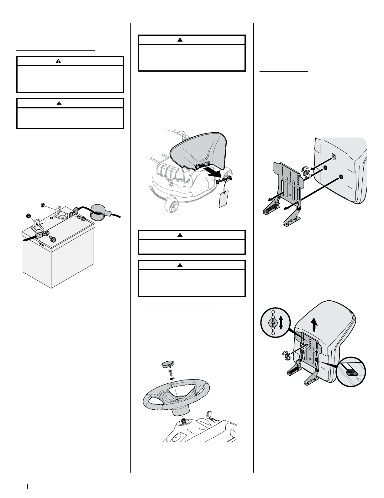
1. Remove the plastic cover, if present, from the
positive battery terminal and attach the red
cable to the positive battery terminal (+) with
the bolt (a) and hex nut (b). See Figure 2-2.
(b)
(b)
(a)
(a)
(c)
Figure 2-2
2. Remove the plastic cover, if present, from the
negative battery terminal and attach the black
cable to the negative battery terminal (–) with
the bolt (a) and hex nut (b). See Figure 2-2.
3. Position the red rubber boot (c) over the
positive battery terminal to help protect it
from corrosion.
NOTE: If the battery is put into service after
the date shown on top/side of battery, charge
the battery as instructed in the Service section
your Operator’s Manual on page 8 prior to
operating the tractor.
Shipping Brace Removal
WARNING
Make sure the tractor’s engine is OFF, remove the ignition
key, and set the parking brake before removing the shipping
brace. Refer to the Controls & Operations section on page 8
for instructions on how to set the parking brake.
Check the cutting deck for a shipping brace
(a) that may be holding the chute deflector (b)
upward for shipment. If the shipping brace (a) is
present, it must be removed before operating
the tractor. Holding the chute deflector (b) fully
upward, remove the shipping brace (a). Lower the
chute deflector (b) and discard the shipping brace
(a). See Figure 2-3.
(a)
(b)
Figure 2-3
WARNING
The shipping brace (a) is used for packaging purposes only, it
must be removed and discarded before operating your tractor.
WARNING
The cutting deck is capable of throwing objects. Failure
to operate the tractor without the chute deflector in the
proper operating position could result in serious personal
injury and/or property damage.
Attaching the Steering Wheel
1. If the steering wheel (a) for your tractor
did not come attached, the hardware for
attaching it has been packed within the
steering wheel (a), beneath the steering
wheel cap (b). Carefully pry OFF the steering
wheel cap (b) and remove the cupped
washer (c) and hex bolt (d).
(d)
(b)
(a)
(e)
(c)
Figure 2-4
2. With the wheels of the tractor pointing
straight forward, place the steering wheel (a)
over the steering shaft (e).
3. Place the cupped washer (c) -- cupped side
down -- over the steering wheel (a) and
secure with the hex bolt (d). See Figure 2-4.
4. Place the steering wheel cap (b) over the
center of the steering wheel (a) and push
downward until it “clicks” into place.
Attaching the Seat
If the seat for your tractor was not attached at the
factory, refer to the following steps.
NOTE: For shipping reasons, seats are either
fastened to the tractor seat’s pivot bracket with
a cable tie, or mounted backward to the pivot
bracket. In either case, remove the seat from its
shipping position.
1. Remove the seat adjustment knob (a) from
the bottom of the seat (b). See Figure 2-5.
(a)
(b)
(c)
Figure 2-5
2. Align the seat (b) over the seat pivot bracket (c)
as shown in Figure 2-5 and fit the seat (b) onto
the seat pivot bracket (c) inserting the two tabs
on the seat (b) bottom into the slots on the seat
pivot bracket (c).
3. Slide the seat (b) rearward in the seat pivot
bracket (c), lining up the center rear slot in
the seat pivot bracket (c) with the remaining
hole in the seat (b) base. See Figure 2-6.
(b)
(c)
(a)
Figure 2-6
NOTE: Be certain the two seat tabs engage
the seat pivot bracket as shown in the
bottom right inset of Figure 2-6.
4. Select the desired position for the seat (b),
and secure with the adjustment knob (a)
removed in Step 1. See Figure 2-6.
5. To adjust the position of the seat, remove
the adjustment knob (a) on the bottom
of the seat (b). Slide the seat (b) forward
or backward as desired. Reinstall the
adjustment knob (a). See Figure 2-6.
Loading ...
Loading ...
Loading ...