MOBILE TYPE AIR CONDITIONER (Local Air Conditioner)
Owner’s Manual
IMPORTANT NOTE:
Before using your air conditioner, please read
this manual carefully and keep it for future reference.
EN
North America Product

Get to know your AC
Drainage guide
Store the unit when not in use
01
04
19
21
23
Cleaning & maintenance
22
TROUBLESHOOTING
24
CONTENTS
Operation instructions
Preparation before installation
Before you get start
Installation instructions
Safety Precautions
product overview
07
09
Installation overview
13
Installation guide
Safety Precautions
WARNING
CAUTION
Explanation of Symbols
Must read the
warning message
01
Read Safety Precautions Before Operation and Installation
To prevent death or injury to the user or other people and property damage, the following
instructions must be followed. Incorrect operation due to ignoring of instructions may
cause death, harm or damage.
This symbol indicates the possibility of property damage or
serious consequences.
This symbol indicates the possibility of personnel injury or loss of life.

02
WARNING
• Installation must be performed according
to the installation instructions. Improper
installation can cause water leakage,
electrical shock, or fire.
• Use only the included accessories and
parts, and specified tools for the
installation. Using nonstandard parts can
cause water leakage, electrical shock, fire,
and injury or property damage.
• Make sure that the outlet you are using is
grounded and has the appropriate voltage.
The power cord is equipped with a
three-prong grounding plug to protect
against shock. Voltage information can be
found on the nameplate of the unit.
• Your unit must be used in a properly
grounded wall receptacle. If the wall
receptacle you intend to use is not
adequately grounded or protected by a time
delay fuse or circuit breaker(the fuse or
circuit breaker needed is determined by the
maximum current of the unit. The maximum
current is indicated on the nameplate
located on unit), have a qualied electrician
install the proper receptacle.
• Do not touch the unit with wet or damp
hands or when barefoot.
• If the air conditioner is knocked over during
use, turn o the unit and unplug it from the
main power supply immediately. Visually
inspect the unit to ensure there is no
damage. If you suspect the unit has been
damaged, contact a technician or customer
service for assistance.
• In a thunderstorm, the power must be cut
o to avoid damage to the machine due to
lightning.
• Your air conditioner should be used in such
a way that it is protected from moisture.
e.g. condensation, splashed water, etc. Do
not place or store your air conditioner
where it can fall or be pulled into water or
any other liquid. Unplug immediately if it
occurs.
• Installation must be performed according
to the installation instructions. Improper
installation can cause water leakage,
electrical shock, or fire.
• Install the unit on a flat, sturdy surface.
Failure to do so could result in damage or
excessive noise and vibration.
• The unit must be kept free from
obstruction to ensure proper function and
to mitigate safety hazards.
• Do not modify the length of the power cord
or use an extension cord to power the unit.
• Do not share a single outlet with other
electrical appliances. Improper power
supply can cause fire or electrical shock.
• Do not install your air conditioner in a wet
room such as a bathroom or laundry room.
Too much exposure to water can cause
electrical components to short circuit.
• Do not install the unit in a location that
may be exposed to combustible gas, as this
could cause re.
• The unit has wheels to facilitate moving.
Make sure not to use the wheels on thick
carpet or to roll over objects, as these could
cause tipping.
• Do not operate a unit that it has been
dropped or damaged.
• The appliance with electric heater shall
have at least 1 meter space to the
combustible materials.
• All wiring must be performed strictly in
accordance with the wiring diagram
located inside of the unit.
• The unit's circuit board(PCB) is designed
with a fuse to provide overcurrent
protection. The specications of the fuse
are printed on the circuit board, such as: T
3.15A/250V, etc.
• When the water drainage function is not in
use, keep the upper and the lower drain
plug rmly to the unit to get rid of choking.
When the drain plug is not in use, keep it
carefully to prevent children from choking.

03
CAUTION
• This appliance can be used by children
aged from 8 years and above and person
with reduced physical, sensory or mental
capabilities or lack of experience and
knowledge if they have been given
supervision or instruction concerning use
of the appliance in a safe way and
understand the hazards involved. Children
shall not playwith the appliance. Cleaning
and user maintenance shall not be made
by children without supervision.
• This appliance is not intended for use by
persons (including childern) with reduced
physical, sensory or mental capabilities or
lack of experience and knowledge, unless
they have been given supervision or
instruction concerning use of the
appliance by a person responsible for their
safety. Children should be supervised to
ensure that they do not play with the
appliance. Children must be supervised
around the unit at all times.
• If the supply cord is damaged, it must be
replaced by the manufacturer,its service
agent or similarly qualied persons in
order to avoid a hazard.
• Do not use this product for functions
other than those
• Before cleaning, turn o the power and
unplug the unit.
• Disconnect the power if strange sounds,
smell, or smoke comes from it.
• Do not press the buttons on the control
panel with anything other than your ngers.
• Do not remove any xed covers. Never use
this appliance if it is not working properly,
or if it has been dropped ordamaged.
• Do not operate or stop the unit by inserting
or pulling outthe power cord plug.
• Do not use hazardous chemicals to clean or
come into contact with the unit. Do not
use the unit in the presenceof inammable
substances or vapour such as alcohol,
insecticides, petrol,etc. described in this
instruction manual.
• Prior to cleaning or other maintenance, the
appliance must be disconnected from the
supply mains.
• Do not remove any xed covers. Never use
this appliance if it is not working properly,
or if it has been dropped or damaged.
• Do not run cord under carpeting. Do not
cover cord withthrow rugs, runners, or
similar coverings. Do not route cord under
furniture or appliances. Arrange cord away
from trac area and where it will not be
tripped over.
• Do not operate unit with a damaged cord,
plug, power fuse or circuit breaker. Discard
unit or return to an authorized service
facility for examination and/or repair.
• To reduce the risk of re or electric shock,
do not use this an with any solid-state
speed control device.
• The appliance shall be installed in
accordance with national wiring
regulations.
• Contact the authorised service t echnician
for repair or maintenance of this unit.
• Contact the authorised installer for
installation of this unit.
• Do not cover or obstruct the inlet or
outlet grilles.
• Always transport your air conditioner in a
vertical positionand stand on a stable, level
surface during use.
• Always contact a qualied person to carry
out repairs. If the damaged power supply
cord must be replaced with a new power
supply cord obtained from the product
manufacturer and not repaired.
• Hold the plug by the head of the power
plug when taking it out.
• Turn o the product when not in use.
• How to x the appliance to its support,
please refer to the installation instructions.

04
Before You Start
Installing your AC
should take about
30 minutes.
The installation must
be carried out in strict
accordance with the
instructions in this manual.
Manual
We recommend
doing this with
a helper.
We’re here if you need us,
please contact your local
distributor for assistance.
Know your mobile type Air Conditioner
AMBIENT TEMPERATURE RANGE FOR UNIT OPERATING
MODE Temperature Range MODE Temperature Range
Cool 16-35°C (60-95°F)
Dry
Heat(pump heat mode)
Heat(electrical heat mode) 13-35°C (55-95°F)
5-30°C (41-86°F)
30°C (86°F)
≥
Energy Rating Information
The energy rating and noise information for this unit is based on the standard installation using an un-extended
exhaust duct without window slider adaptor (as shown in the Installation section of this manual). At the same time, the
unit must be operate on the COOL MODE and HIGH FAN SPEED by remote controller.
The unit with 3 meters extended exhaust duct is running by using 2 exhaust ducts
(Diameter:150mm, Length:1.5m + Diameter: 130mm, Length: 1.5m) .The Energy rating and noise information for unit with
3 meters extended exhaust duct is not assessed. (For some models)
NOTE:
We recommend that operating the unit at room temperature below 35°C . Since there is a risk that the unit with 3 meters
extended exhaustduct would not work at room temperature above 35°C under some extreme conditions, such as the
lower air intake be blocked for 50%.
How to Stay Cool with a New Portable Air Conditioner
(For the models comply with the requirements of Department Of Energy in US).
Because of a new federal test procedure for Portable Air Conditioners, you may notice that the cooling capacity claims on
portable air conditioner packaging are signicantly lower than that of models produced prior to 2017. This is due to changes in the
test procedure, not to the portable air conditioners themselves.
Preparations before installation

05
Why newer products have lower cooling capacity than older models.
How to purchasing a mobile type air conditioner.
The right air conditioner helps you cool a room eciently. An undersized unit won't cool adequately while one that's too
large will not remove enough humidity, leaving the air feeling damp. To nd the proper air conditioner, determine the square
footage of the room you want to cool by multiplying the room length by its width. You also need to know the air conditioner's
BTU (British Thermal Unit) rating, which indicates the amount of heat it can remove from a room. A higher number means more
cooling power for a larger room. (Be sure you are comparing only newer models to each other older models may appear to
have a higher capacity, but are actually the same). Be sure to “size up” if your portable air conditioner will be placed in a very
sunny room, in a kitchen, or in a room with high ceilings. After you’ve found the right cooling capacity or your room, you can
look at other features.
Federal regulations require manufacturers to calculate cooling capacity based on a specic test procedure, which was changed
just this year. Models manufactured before 2017 were tested under a dierent procedure and cooling capacity is measured
dierently than in prior years’models. So, while the BTUs may be lower, the actual cooling capacity of the air conditioners
has not changed.
What is SACC ?
SACC is the representative value of Seasonally Adjusted Cooling Capacity, in Btu/h, as determined in accordance with the
DOE test procedure at title 10 Code of Federal Regulations (CFR) 430, subpart B, appendix CC and applicable sampling plans.
-Make sure that you install your unit on an even surface to minimize noise and vibration.
-The unit must be installed near a grounded plug, and the Collection Tray Drain (found on the back of the unit) must be accessible.
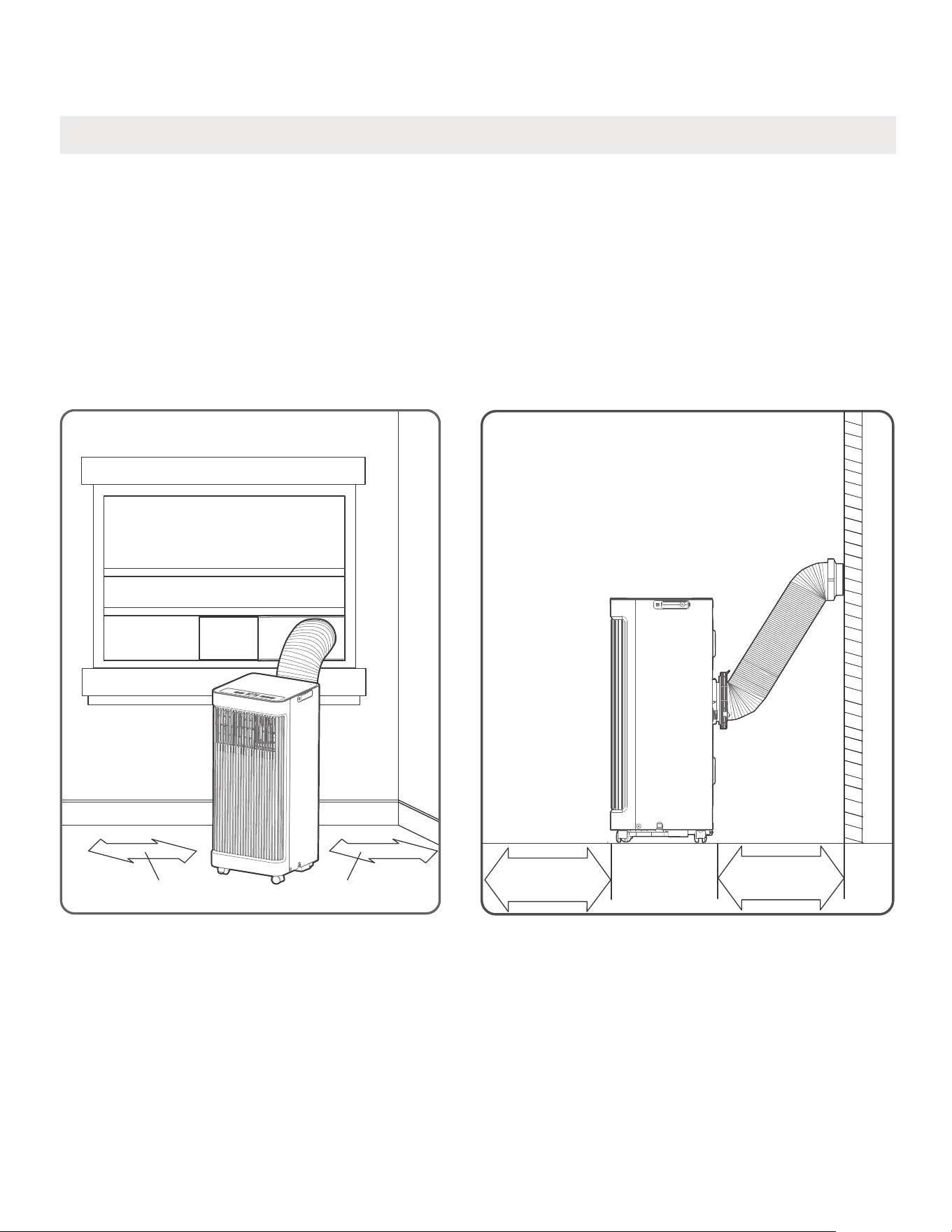
-The unit should be located at least 30cm (12”) from the nearest wall to ensure proper air conditioning. The air outlet of the unit
should be at least 50cm(19.7”) away from obstacles.
-DO NOT cover the Intakes, Outlets or Remote Signal Receptor of the unit, as this could cause damage to the unit.
06
Unit Installation Location Restricted Space Requirements
PRODUCT INSTALLATION LOCATION
Your installation location should meet the following requirements:
≥30cm(12’’)
≥50cm
19.7’’
≥50cm
19.7’’
≥30cm(12’’)
07
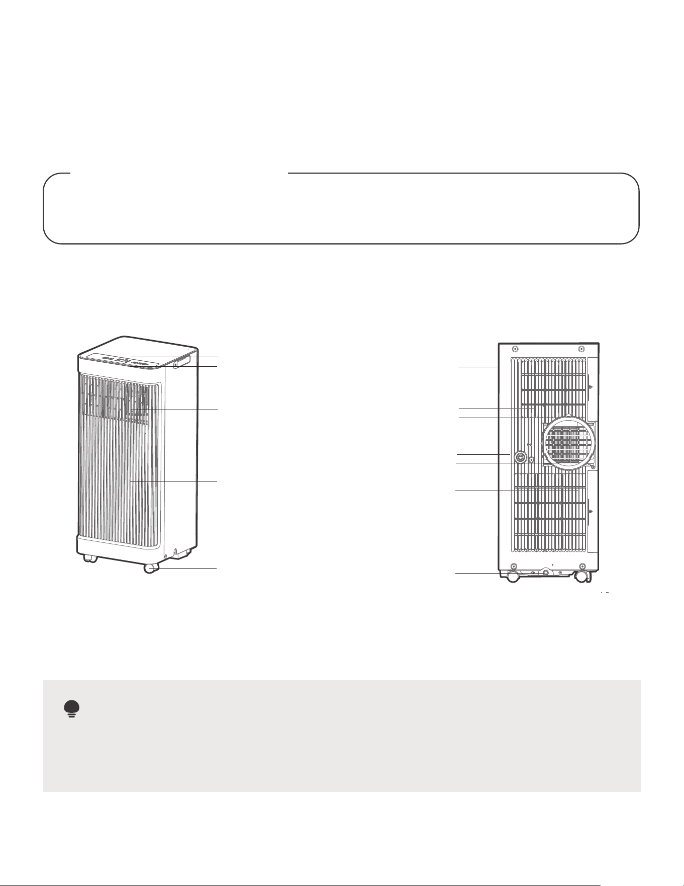
All the illustrations in the manual are for explanation purpose only. Your machine may be slightly dierent. The actual shape
shall prevail. The unit can be controlled by the unit control panel alone or with the remote controller. This manual does not
include Remote Controller Operations, see the <<Remote Controller Instruction>> packed with the unit for details.
Control panel
Remote signal receptor
Front panel
Caster
Vertical louver control
lever-manual adjustment
(On some models)
NOTE ON ILLUSTRATIONS:
Product Overview
Design Notice
In order to ensure the optimal performance of our products, the design
specications of the unit remote control are subject to change without prior notice.
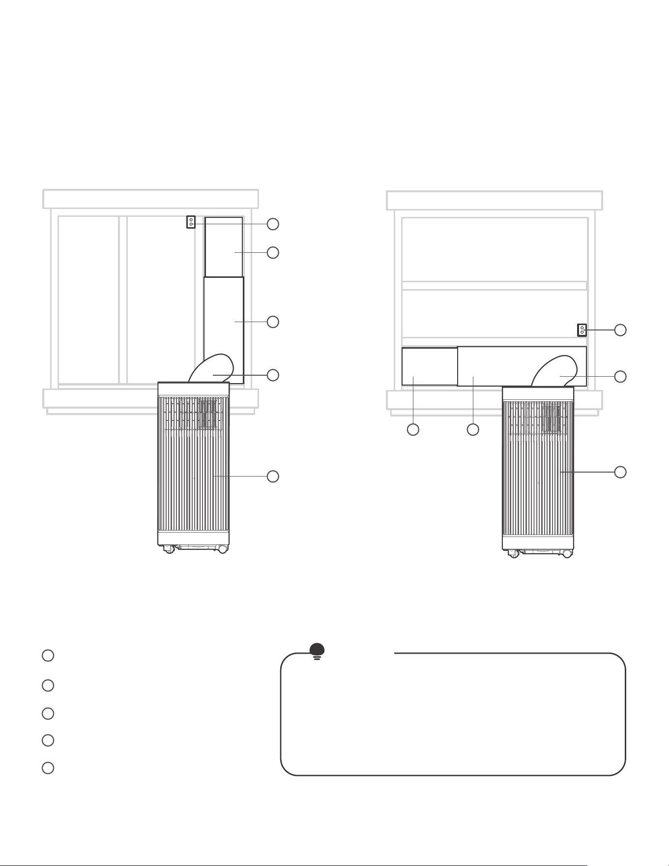
Front View
Rear View
Handle
(both sides)
Air lter
upper air intake
Air outlet
Lower air intake
Drain outlet
Bottom tray
drain outlet
model A
08
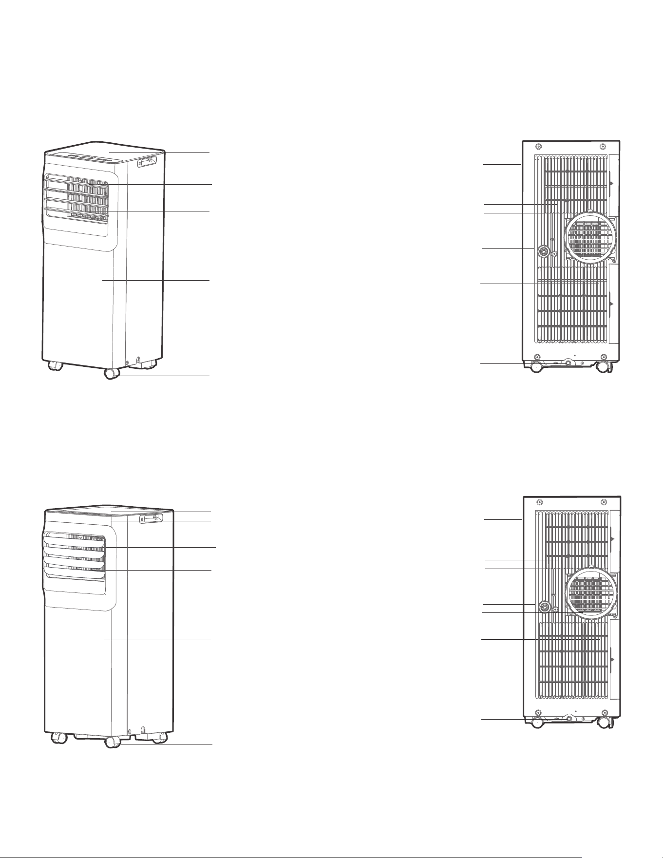
louver control
lever-manual adjustment
(On some models)
Control panel
Remote signal receptor
Front panel
Caster
louver control
Curved air outlet
lever-manual adjustment
(On some models)
Control panel
Remote signal receptor
Air outlet
Front panel
Caster
Front View Rear View
Handle
(both sides)
Air lter
upper air intake
Air outlet
Lower air intake
Drain outlet
Bottom tray
drain outlet
Rear View
Handle
(both sides)
Air lter
upper air intake
Air outlet
Lower air intake
Drain outlet
Bottom tray
drain outlet
Model B
Model C
Front View
09
Window Slider A
Security Bracket and 2 Screws
Window Slider B
Extended Exhaust Hose
Installation
Overview
Installation Completion Display
NOTE
Local Air Conditioner
1
2
3
4
5
Sliding Window Installation
Hung Window Installation
1
5
2
3
3
1 2
5
4
4
Illustrations in this manual are for explanatory
purposes. The actual shape of your indoor
unit may be slightly dierent. The actual
shape shall prevail.
10
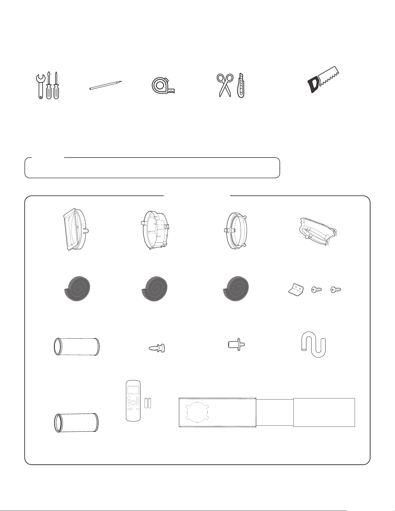
Unit Adaptor (1pc) Window Slider Adaptor(1pc)
Extended Exhaust Hose(1pc*)
Exhaust Hose Adaptor(1pc*) Air exhaust passage(1pc*)
Exhaust Hose
Window
Slider A (1pc)
Window
Slider B (1pc)
Window
Slider C (1pc*)
Foam Seal A (Adhesive) 2 pc/4 pc(*)
Foam Seal B (Adhesive) 2 pc Foam Seal C (Non-adhesive)1 pc/2 pc(*) Security Bracket and 2 Screws (1 set)
Drain Hose (1pc)
Bolt (1pc/2pc*)
Drain Hose Adaptor (1pc*)
(only for heat pump mode)
NOTE
Remote Controller
and Battery (only
for remote control
models)(1set*)
List of Installation Tools (not included)
Installation accessories
Items with (*) are on some models. Slight variations in design may occur.
Screwdriver & wrench
A tape measure Scissors or Knife
Pencil
Saw (On some models, to shorten
window adaptor for narrow windows)
North America
11
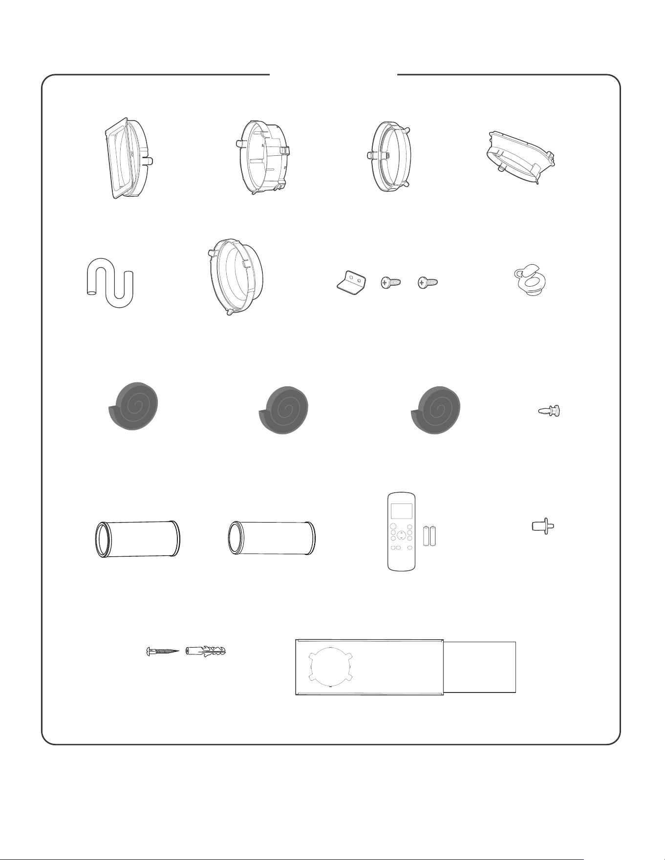
Other Regions
Wall Exhaust Adaptor A
(only for wall installation
models)(1pc*)
Wall Exhaust Adaptor B
(with cap)(only for wall
installation models)1 pc(*)
Screw and anchor
(only for wall installation
models)4 set(*)
Unit Adaptor (1pc) Window Slider Adaptor(1pc*) Exhaust Hose Adaptor(1pc*) Air exhaust passage(1pc*)
Foam Seal A (Adhesive)
(2pc*)
Foam Seal B (Adhesive)
(2pc*)
Foam Seal C (Non-adhesive)
1 pc(*)
Exhaust Hose
Security Bracket and 2 Screws (1 set*)Drain Hose (1pc)
Extended Exhaust Hose(1pc*)
Window
Slider A (1pc*)
Window
Slider B (1pc*)
Bolt (1pc*)
Drain Hose Adaptor (1pc*)
(only for heat pump mode)
Remote Controller
and Battery (only
for remote control
models)(1set*)
12
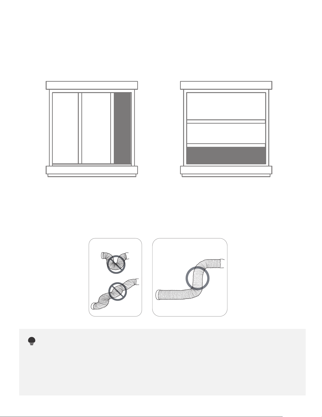
Confirm your window type (window
type and opening size of dierent types)
Sliding Window Installation Hung Window Installation
To ensure proper function, DO NOT overextend or bend the hose. Make sure that there is no
obstacle around the air outlet of the exhaust hose (in the range of 500mm) in order to the
exhaust system works properly. All the illustrations in this manual are for explanation purpose only.
Your air conditioner may be slightly dierent. The actual shape shall prevail.
NOTE:
INCORRECT
CORRECT
For Optimal Performance in Operation
13
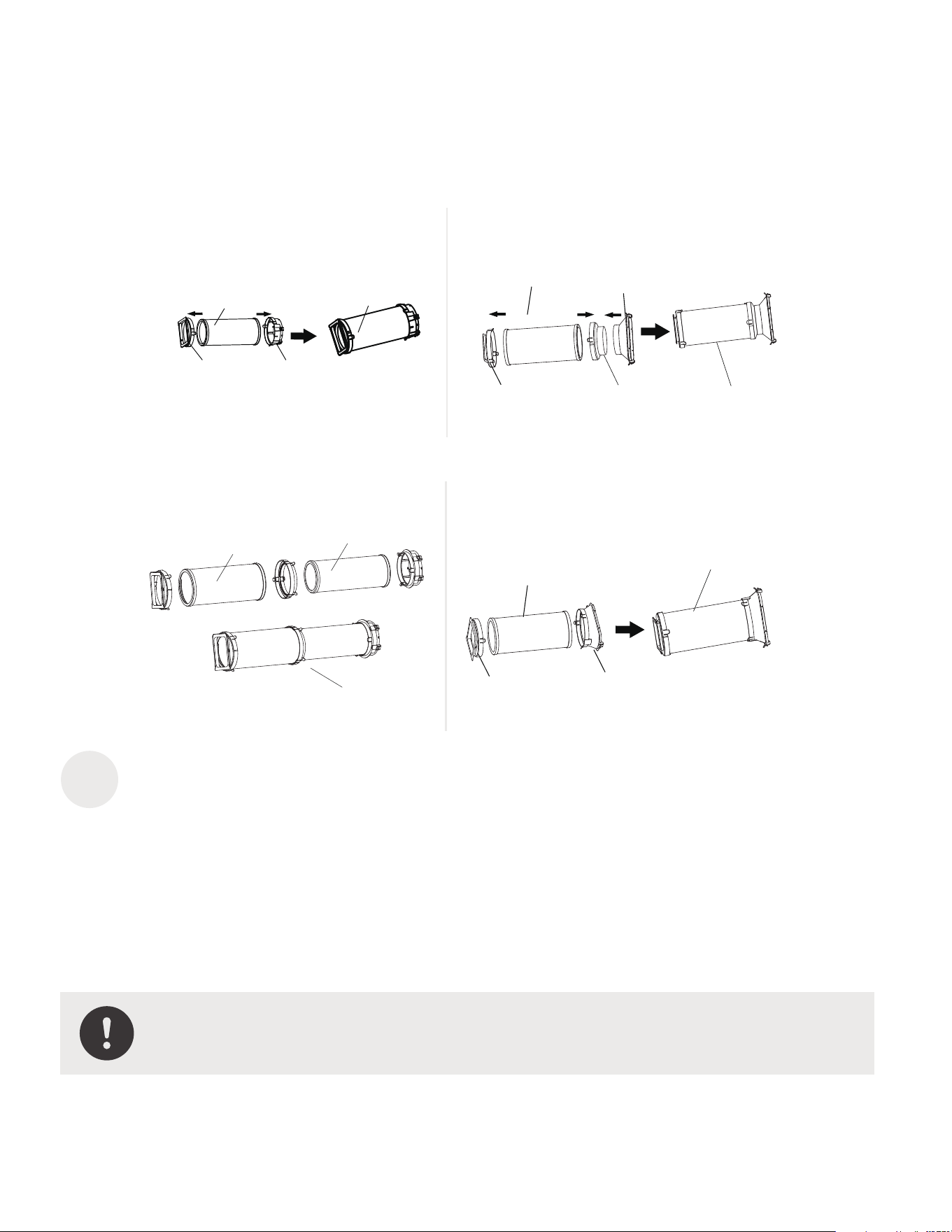
1
Exhaust Hose and Adaptors Installation
NOTE: Please install the exhaust hose assembly according to the ttings
in your kit.
Unit adaptor
Window slider
adaptor
Exhaust hose
Exhaust hose
assembly
Model BModel A
Window slider
adaptor
Exhaust hose
assembly
Exhaust hose
Air exhaust
passage
Unit adaptor
Exhaust hose
Extended Exhaust
hose
Exhaust hose assembly
Model DModel C
Exhaust hose
assembly
Exhaust hose
Unit adaptor
Air exhaust
passage
Press the exhaust hose(or extended exhaust hose) into the window slider adaptor
and unit adaptor, clamp automatically by elastic buckles of the adaptors.
The Exhaust Hose Assembly Installation (window type)
14
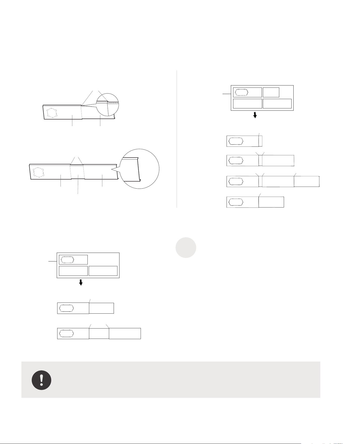
Connect the Adaptor to the Unit & the Window
MODEL A MODEL B
1+2:
Bolt
1+2+3:
Bolt
Bolt
1+2+3+4:
Bolt
BoltBolt
1+4:
Bolt
Window
Sliders
After assembly
Before assembly
Window
Sliders
After assembly
Before assembly
MODEL C
Bolt
Bolt
1+2:
1+2+3:
Bolt
2
NOTE:
Please base your window slider installation on the accessories in your kit and
the width of your window.
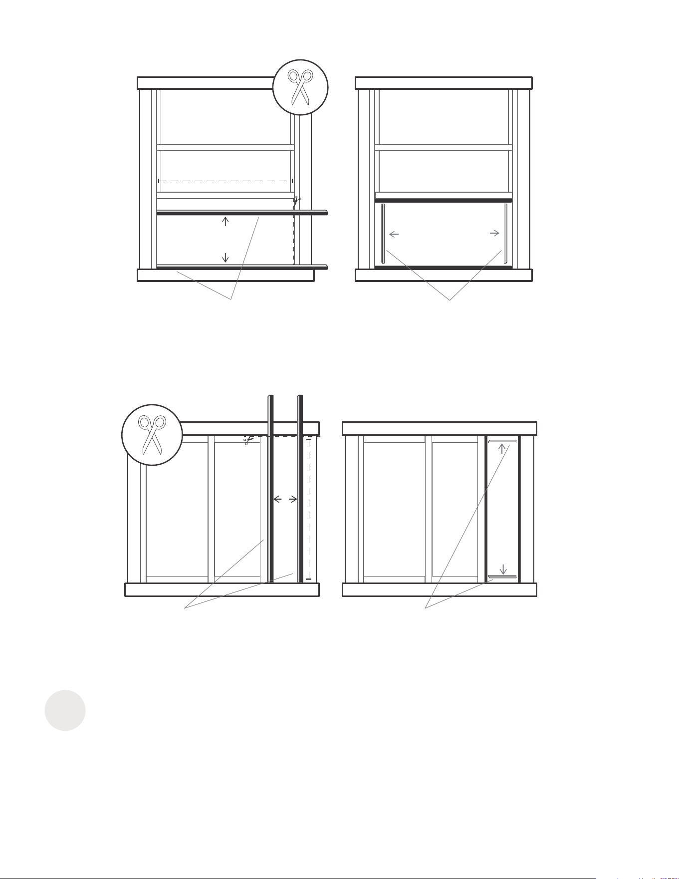
Preparing the Adjustable
Window Slider
Choose the window sliders according the size of your
window. Sometimes, it needs to be cut short to meet the
window size, please take extra care to cut it properly.
Use bolts to fasten the window sliders once they
are adjusted to the Proper length.
Window slider A Window slider B
Bolt
Window slider A
Window slider B
Window slider C
Bolt
Inside
Outside
or
15
Foam seal B
(Adhesive type-shorter)
Foam seal A
(Adhesive type)
Foam seal B
(Adhesive type-shorter)
Foam seal A
(Adhesive type)
Hung Window Installation
Sliding Window Installation
3
Complete sealing of window
Cut the adhesive foam seal A and B strips to the proper lengths, and attach them to the window sash and frame as shown.
16
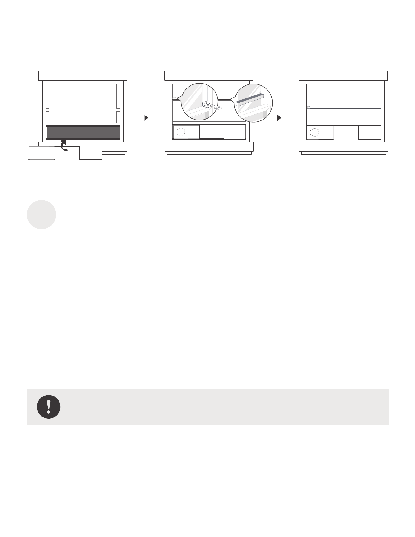
4
NOTE: Once the Exhaust Hose assembly and Adjustable Window Slider are
prepared, choose from one of the following two installation methods.
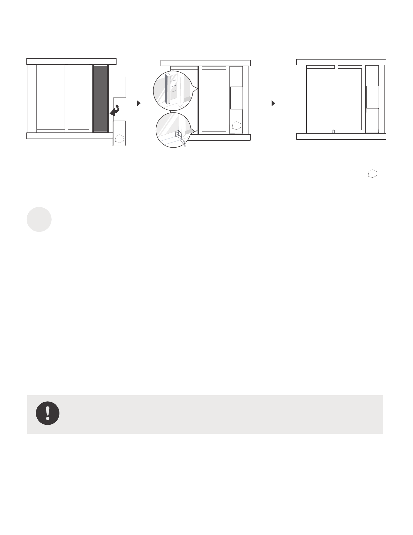
Hung Window Installation
Insert the window slider assembly into the window opening.
If desired, install the security bracket with 2 screws as shown.
Step 2:
Step 1:
Step 3:
Cut the non-adhesive foam seal C strip to match the width of the window. Insert the seal between
the glass and the window frame to prevent air and insects from getting into the room.
17
5
Sliding Window Installation
Insert the window slider assembly into the window opening.
If desired, install the security bracketwith 2 screws as shown.
Cut the non-adhesive foam seal C strip to match the height of the window. Insert the seal
between the glass and the window frame to prevent air and insects from getting into the room.
Step 1:
Step 2:
Step 3:
NOTE: Once the Exhaust Hose assembly and Adjustable Window Slider are
prepared, choose from one of the following two installation methods.
18
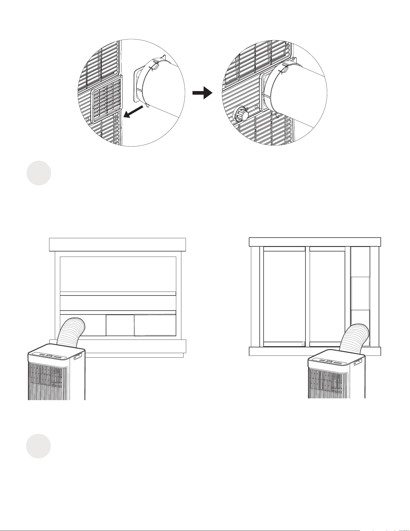
Install the Exhaust Hose Assembly to the Unit
Push the Exhaust hose into the airoutlet opening of the unit along the arrow direction.
6
7
Connect the Adaptor to the Unit and the Window
Insert the window slider adaptor into the hole of the window slider.
Hung Window Installation Sliding Window Installation
Shows the set temperature while
on Cool, or Auto mode. It shows
the room temperature on DRY
and FAN modes.
Shows Error codes:
EH00-EEPROM error.
EH60-Room temperature sensor
error.
EH61-Evaporator temperature
sensor error.
EC52-Condenser temperature
sensor error
(on some models).
EH0b-Display panel
communication error.
EC-Refrigerant leakage detection
malfunction(on some models).
Shows protection code:
P1-Bottom tray is full--Connect
the drain hose and drain the
collected water away. If
protection repeats, call for
service.
NOTE: When one of the above
malfunctionsoccurs, turn o the
unit, and check for any
obstructions. Restart the unit, if
the malfunction is still present,
turn o the unit and unplug the
power cord. Contact the
manufacturer, its service agents
or a similar qualied person for
service.
Press to control the fan speed in
four steps HIGH, LOW, Cont and
AUTO. The fan speed indicator
light illuminates under dierent
fan settings.
Press the "MODE" button until the
"Cool" indicator light comes on.
Press the ADJUST buttons "+" or
"-" to select your the COOL mode.
Press the "MODE" button until the
"Auto" indicator light
comes on. In this mode, the fan
speed or the temperature
will be adjusted automatically.
Selects the appropriate operating
mode. Each time you press the
button, the mode is selected in a
sequence that goes from AUTO,
DRY, COOL andFAN, The mode
indicator light illuminates under
the dierent modesetting.
Used to adjust
(increasing/decreasing)
temperature settings in 1°C/2°F
(or 1°F) increments in a range
of 16°C/60°F to 30°C/88°F (or
86°F).
NOTE: The control is capable of
displaying temperature in
degrees Fahrenheit or degrees
Celsius. To convert from one to
the other, press and hold the Up
and Down buttons atthe same
time for 3 seconds.
19
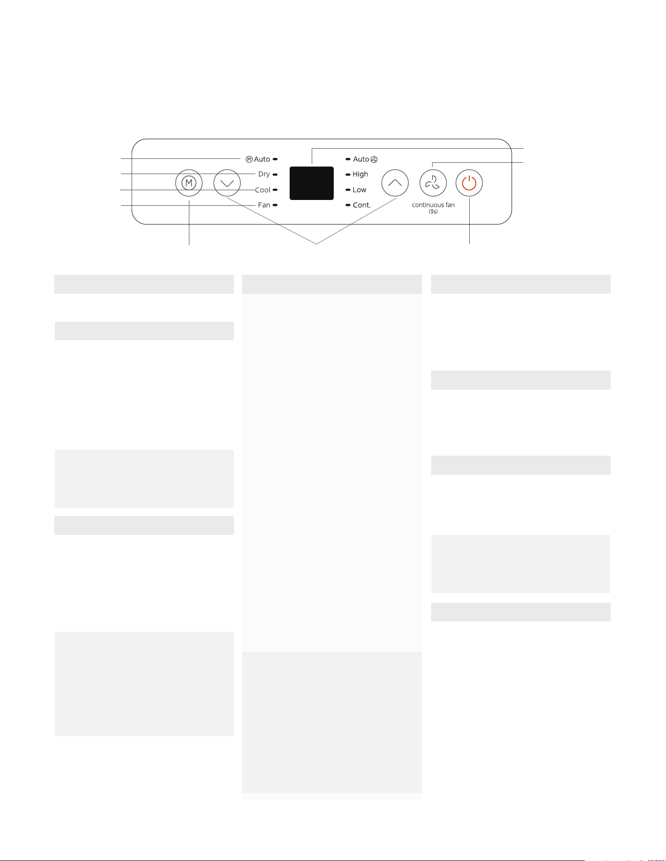
Get to know your AC
Electronic control
operating instructions
1
9
5
6
7
8
2
4
3
2. MODE function
Power switch on/o.
NOTE: In AUTO mode,
the FAN speed will be
adjusted automatically.
3. UP and DOWN buttons
4. Display 5. Fan Function
6. COOL Mode
Press the "MODE" button until the
"Cool" indicator light comes on.
Press the ADJUST buttons "+" or
"-" to select your the COOL mode.
NOTE: Keep windows and doors
closed for the best dehumidifying
eect. Do not put the duct to
window.
7. DRY Mode
8. AUTO Mode
1. POWER button

20
9. Continuous Fan function
10. Other features
In COOL or DRY mode, press the Fan button for 3 seconds to turn on or o the continuous fan function. When
the function is turned on, the Cont. fan light will illuminate, indicating the fan will run continuously. When the
function is turned o, the Cont. fan light will go out, indicating thatthe fan will stop when the compressor stops.
FOLLOW ME/TEMP SENSING feature (On some models)
This feature can be activated from the remote control ONLY. There is no indicator light on the control panel. The
remote control serves as a remote thermostat allowing for the precise temperature control at its location. To
activate the Follow Me/Temp Sensing feature, point the remote control towards the unit and press the Follow
Me/Temp Sensing button. The remote control will send this signal to the AC until press the Follow Me/Temp
Sensing button again. If the unit does not receivethe Follow Me/Temp Sensing signal during any 7 minutes
interval, the unit will exit the Follow Me/Temp Sensing mode.
NOTE: This feature is unavailabe under FAN or DRY mode.
21
Drainage guide
Remove the
bottom
drain plug
When the water level of the bottom tray reaches a predetermined level,
the unit beeps 8 times, the digital display area shows "P1" . At this time
the air conditioning/dehumidication process will immediately stop.
However, the fan motor will continue to operate(this is normal).
Carefully move the unit to a drain location, remove the bottom drain
plug and let the water drain away. Reinstall the bottom drain plug and
restart the machine until the "P1" symbol disappears. If the error repeats,
call for service.
NOTE: Be sure to reinstall the bottom drain plug rmly to revent
leakage before using the unit.
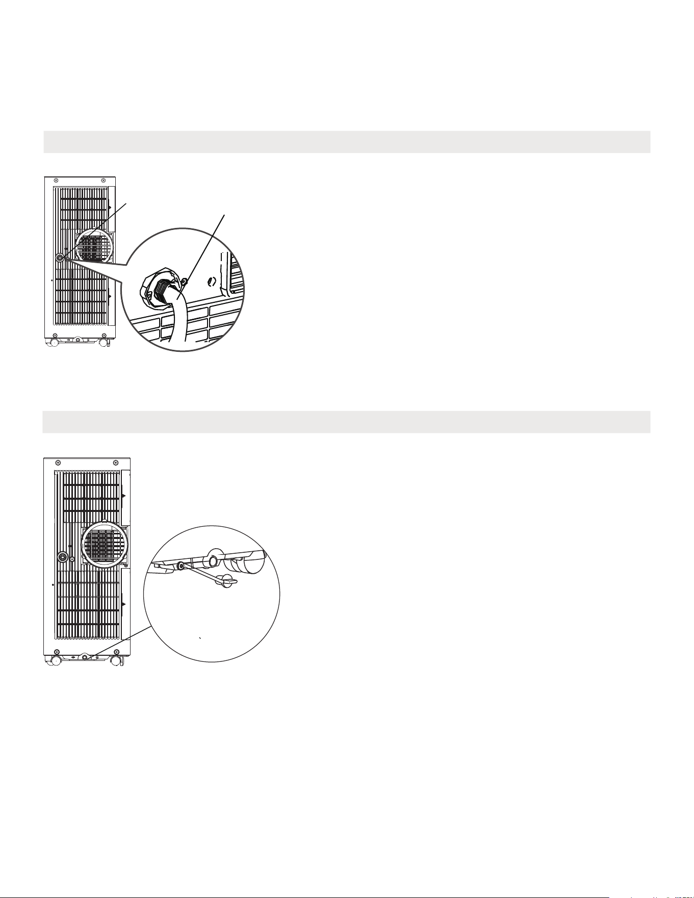
Water collection tray Drainage Guide
During dehumidifying modes, remove the drain plug from the back of
the unit, install the drain connector (5/8" universal female mender) with
3/4" hose(locally purchased). For the models without drain connector,
just attach the drain hose to the hole. Place the open end of the hose
directly over the drain area in your basement oor.
NOTE: Make sure the hose is secure so there are no leaks. Direct the
hose toward the drain,making sure that there are no kinks that will
stop the warter owing. Place the end of the hose into the drain
andmake sure the end of the hose is down to let the water ow
smoothly. When the continuous drain hose is not used, ensure that the
drain plug and knob are installed rmly to prevent leakage.
Step 1:
Remove the
drain plug
Dehumidifying Mode Drainage Guide
Step 2:
Install the
continuous
drain hose
22
How to clean & maintenance your AC
Cleaning
& Maintenance
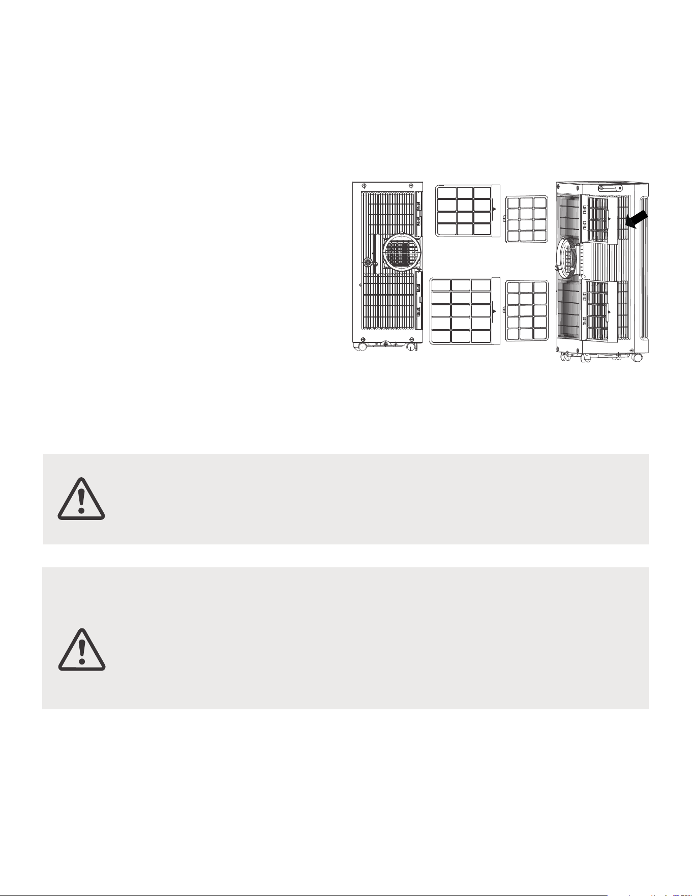
Air Filter & Cabinet Cleaning
Remove the air filter
CAUTION:
CAUTION:
DO NOT operate the unit without lter because dirt and lint will clog it and
reduce performance.
Maintenance Tips
• Be sure to clean the air lter every 2 weeks for
optimal performance.
• The water collection tray should be drained
immediately after P1 error occurs, and before
storage to prevent mold.
• In households with animals, you will have to
periodically wipe down the grill to prevent
blocked airow due to animal hair.
Clean the unit using a damp, lint-free cloth and mild
detergent. Dry the unit with a dry, lint-free cloth.
• Always unplug the unit before cleaning or servicing.
• DO NOT use ammable liquids or chemicals to cleanthe unit.
• DO NOT wash the unit under running water. Doing so causes electrical danger.
• DO NOT operate the machine if the power supply was damaged during cleaning.
A damaged power cord must be replaced with a new cord from the manufacturer.
23
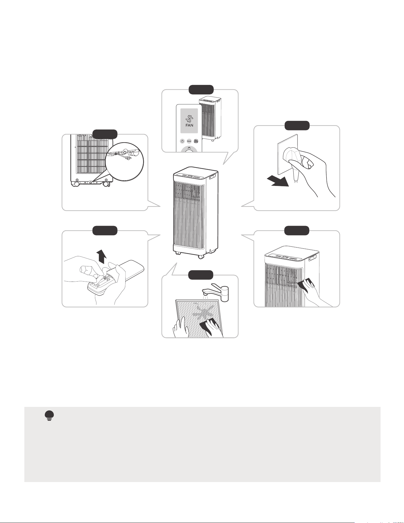
Store the Unit when not in Use
NOTE
12hours
Be sure to store the unit in a cool, dark place. Exposure to direct sunshine or extreme heat can shorten
the lifespan of the unit. The cabinet and front may be dusted with an oil-free cloth or washed with a
cloth dampened in a solution of warm water and mildliquid dishwashing detergent. Rinse thoroughly
and wipe dry. Never use harsh cleansers, wax or polish on the cabinet front. Be sure to wring excess
water from the cloth before wiping around the controls. Excess water in or around the controls may
cause damage to the unit.
Step6
Step 3
Step4
Step 1
Step 2
Step 5
*Please refer to the actual
plug, and the legend is for
reference only.
*Drain the unit‘s water collection
tray then reinstall the bottom
drain plug back in.
· Drain the unit’s water collection tray according to the instructions in the following section.
· Run the appliance on FAN mode for 12 hours in a warm room to dry it and prevent mold.
· Turn o the appliance and unplug it.
· Clean the air lter according to the instructions in the previous section. Reinstall the clean, dry lter before storing.
· Remove the batteries from the remote control.

24
Problem Solving
TROUBLESHOOTING
Common Issues
The following problems are not a malfunction and in most situations will not require repairs.
Problem Possible Causes Solution
Unit does not turn
on when pressing
ON/OFF button
P1 Protection Code
In COOL mode: room
temperature is lower than
the set temperature
Reset the temperature
The air lter is blocked with
dust or animal hair
The unit is low on
refrigerant
Temperature setting is too
high
The windows and doors in
the room are open
The room area is too large
Unit does
not cool well
Exhaust hose is not
connected or is blocked
There are heat sources
inside the room
Turn o the unit and clean the lter according to instructions
Call a service technician to inspect the unit and top
o refrigerant
Decrease the set temperature
Make sure all windows and doors are closed
Double-check the cooling area
Turn o the unit, disconnect the hose, check for blockage
and reconnect the hose
Remove the heat sources if possible
The unit is noisy
and vibrates too
much
The unit makes a
gurgling sound
The ground is not level
Place the unit on a at, level surface
The air lter is blocked with
dust or animal hair
Turn o the unit and clean the lter according to instructions
This sound is caused by the
ow of refrigerant inside
the unit
This is normal
The Water Collection Tray is full. Turn o the unit, drain the
water from the Water Collection Tray and restart the unit.

The design and specications are subject to change without prior notice for product improvement. Consult with the sales agency or
manufacturer for details. Any updates to the manual will be uploaded to the service website, please check for the latest version.