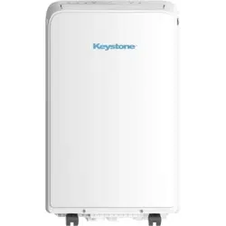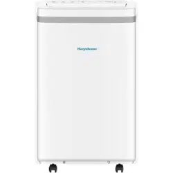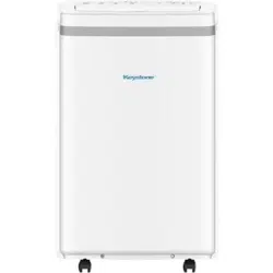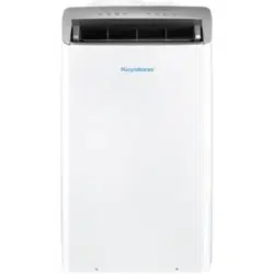
lll
KSTAP10PINV, KSTAP12PINV, KSTAP121HINV

Safety Precautions
. ..................................................................................................................
Safety Precautions
Installation Instructions
Operating Instructions
Maintenance
Table of Contents
Control Panel Features...............................................................................................................
Operation Instructions................................................................................................................
Other features...........................................................................................................................
Water drainage..........................................................................................................................
Water drainage(For Heating Mode)............................................................................................
Safety Precautions.....................................................................................................................
Air Filter Cleaning ......................................................................................................................
Troubleshooting Tips ................................................................................................................
Unit Cleaning ...........................................................................................................................
Store the unit when not in use .................................................................................................
Preparation................................................................................................................................
Design Notice.............................................................................................................................
Ambient Temperature Range For Unit Operating........................................................................
Troubleshooting Tips
01
10
10
10
Energy Rating Information ........................................................................................................
Recommend Installation.............................................................................................................
Choosing The Right Location......................................................................................................
Tools Needed.............................................................................................................................
Accessories.................................................................................................................................
Window Installation Kit..............................................................................................................
Installation.................................................................................................................................
HEAT PUMP HOSE INSULATION FOAM(only for heat pump mode).............................................
11
10
11
12
12
12
14
17
18
19
20
21
22
23
23
23
23
24

Safety
Precautions
Safety
Read Safety Precautions Before Operation and Installation
To prevent death or injury to the user or other people and property damage, the
following instructions must be followed. Incorrect operation due to ignoring of
instructions may cause death, harm or damage.
WARNING
•
•
•
•
•
•
•
•
•
•
•
•
•
•
•
Safety Precautions
Do not operate a unit that it has been dropped or damaged.
The appliance with electric heater shall have at least 1 meter space to the combustible
materials.
Do not touch the unit with wet or damp hands or when barefoot.
If the air conditioner is knocked over during use, turn off the unit and unplug it from the main
power supply immediately. Visually inspect the unit to ensure there is no damage. If you
suspect the unit has been damaged, contact a technician or customer service for assistance.
Page 1
WARNING
CAUTION
This symbol indicates the possibility of
property damage or serious consequences.
Installation must be performed according to the installation instructions. Improper installation
can cause water leakage, electrical shock, or fire.
Use only the included accessories and parts, and specified tools for the installation. Using non-
standard parts can cause water leakage, electrical shock, fire, and injury or property damage.
Make sure that the outlet you are using is grounded and has the appropriate voltage.
The power cord is equipped with a three-prong grounding plug to protect against shock.
Voltage information can be found on the nameplate of the unit.
Your unit must be used in a properly grounded wall receptacle. If the wall receptacle you
intend to use is not adequately grounded or protected by a time delay fuse or circuit breaker
(the fuse or circuit breaker needed is determined by the maximum current of the unit. The
maximum current is indicated on the nameplate located on unit), have a qualified electrician
install the proper receptacle.
Install the unit on a flat, sturdy surface. Failure to do so could result in damage or excessive
noise and vibration.
The unit must be kept free from obstruction to ensure proper function and to mitigate safety
hazards.
Do not modify the length of the power cord or use an extension cord to power the unit.
Do not share a single outlet with other electrical appliances. Improper power supply can
cause fire or electrical shock.
Do not install your air conditioner in a wet room such as a bathroom or laundry room. Too
much exposure to water can cause electrical components to short circuit.
Do not install the unit in a location that may be exposed to combustible gas, as this could
cause fire.
The unit has wheels to facilitate moving. Make sure not to use the wheels on thick carpet or
to roll over objects, as these could cause tipping.
This symbol indicates the possibility of
personnel injury or loss of life.

Safety
Precautions
Page 2
•
•
•
•
•
In a thunderstorm, the power must be cut off to avoid damage to the machine due to lightning.
Your air conditioner should be used in such a way that it is protected from moisture.
e.g. condensation, splashed water, etc. Do not place or store your air conditioner where it can
fall or be pulled into water or any other liquid. Unplug immediately if it occurs.
All wiring must be performed strictly in accordance with the wiring diagram located inside of
the unit.
The unit's circuit board(PCB) is designed with a fuse to provide overcurrent protection. The
specifications of the fuse are printed on the circuit board, such as: T 3.15A/250V, etc.
When the water drainage function is not in use, keep the upper and the lower drain plug firmly
to the unit to get rid of choking. When the drain plug is not in use, keep it carefully to prevent
children from choking.
•
•
•
•
•
•
•
•
•
•
•
•
•
•
This appliance can be used by children aged from 8 years and above and person with reduced
physical, sensory or mental capabilities or lack of experience and knowledge if they have been
given supervision or instruction concerning use of the appliance in a safe way and understand
the hazards involved. Children shall not play with the appliance. Cleaning and user maintenance
shall not be made by children without supervision. (be applicable for the European Countries)
This appliance is not intended for use by persons (including childern) with reduced physical,
sensory or mental capabilities or lack of experience and knowledge, unless they have been
given supervision or instruction concerning use of the appliance by a person responsible for
their safety. Children should be supervised to ensure that they do not play with the appliance.
Children must be supervised around the unit at all times.(be applicable for other countries
except the European Countries )
If the supply cord is damaged, it must be replaced by the manufacturer,its service agent or
similarly qualified persons in order to avoid a hazard.
CAUTION
•
•
•
•
Disconnect the power if strange sounds, smell, or smoke comes from it.
Do not press the buttons on the control panel with anything other than your fingers.
Do not remove any fixed covers. Never use this appliance if it is not working properly, or if
it has been dropped or damaged.
Do not operate or stop the unit by inserting or pulling out the power cord plug.
Do not use this product for functions other than those described in this instruction manual.
Before cleaning, turn off the power and unplug the unit.
Prior to cleaning or other maintenance, the appliance must be disconnected from the supply
mains.
Do not remove any fixed covers. Never use this appliance if it is not working properly, or if it
has been dropped or damaged.
Do not run cord under carpeting. Do not cover cord with throw rugs, runners, or similar cov-
erings. Do not route cord under furniture or appliances. Arrange cord away from traffic area
and where it will not be tripped over.
Do not operate unit with a damaged cord, plug, power fuse or circuit breaker. Discard unit or
return to an authorized service facility for examination and/or repair.
To reduce the risk of fire or electric shock, do not use this fan with any solid-state speed con-
trol device.
The appliance shall be installed in accordance with national wiring regulations.
Contact the authorised service technician for repair or maintenance of this unit.
Contact the authorised installer for installation of this unit.
Do not cover or obstruct the inlet or outlet grilles.
UV-C lamp(Applicable to the unit contains an UV-C lamp only)
This appliance contains an UV emitter. Do not stare at the light source.
WARNING
This appliance contains a UV-C lamp. Read the maintenance instructions before opening the
appliance.
1. Do not operate UV-C lamps outside of the appliance.
2. Appliances that are obviously damaged must not be operated.
3. Unintended use of the appliance or damage to the housing may result in the escape of dan-
gerous UV-C radiation.
UV-C radiation may, even in small doses, cause harm to the eyes and skin.
4. Before opening doors and access panels bearing the ULTRAVIOLET RADIATION hazard symbol
for the conducting USER
MAINTENANCE, it is recommended to disconnect the power.
5. The UV-C lamp can not be cleaned, repaired and replaced.
6. UV-C BARRIERS bearing the ULTRAVIOLET RADIATION hazard symbol should not be removed.
Safety
Precautions
Page 3
Note about Fluorinated Gasses(Not applicable to the unit using R290 Refrigerant)
1.
Fluorinated greenhouse gases are contained in hermetically sealed equipment. For specific
information on the type, the amount and the CO2 equivalent in tonnes of the fluorinated
greenhouse gas(on some models), please refer to the relevant label on the unit itself.
2.
Installation, service, maintenance and repair of this unit must be performed by a certified
technician.
3.
Product uninstallation and recycling must be performed by a certified technician.
Sociable Remark
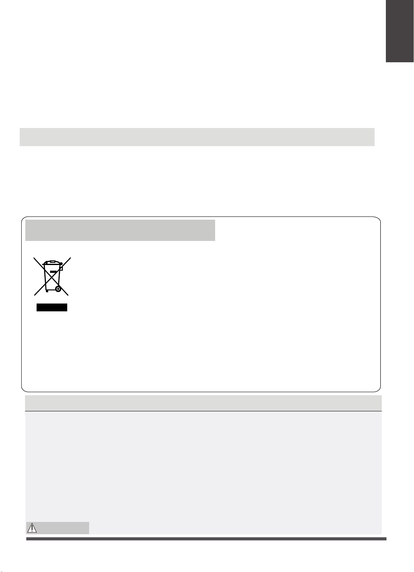
DISPOSAL: Do not dispose this product as unsorted municipal waste.
Collection of such waste separately for special treatment is necessary.
It is prohibited to dispose of this appliance in domestic household waste.
For disposal, there are several possibilities:
When using this appliance in the European countries, the following information must be followed:
· The municipality has established collection systems, where electronic waste can be disposed
of at least free of charge to the user.
· When buying a new product, the retailer will take back the old product at least free of charge.
· The manufacture will take back the old appliance for disposal at least free of charge to the user.
· As old products contain valuable resources, they can be sold to scrap metal dealers. Wild
disposal of waste in forests and landscapes endangers your health when hazar do us
substances leak into the ground-water and find their way into the food chain.
•
•
•
•
•
Do not use hazardous chemicals to clean or come into contact with the unit. Do not use the unit
in the presence of inflammable substances or vapour such as alcohol, insecticides, petrol,etc.
Always transport your air conditioner in a vertical position and stand on a stable, level surface
during use.
Always contact a qualified person to carry out repairs. If the damaged power supply cord must
be replaced with a new power supply cord obtained from the product manufacturer and not
repaired.
Hold the plug by the head of the power plug when taking it out.
Turn off the product when not in use.
For R290(Not applicable for North America)
amount of refrigerant (kg)
4
5
6
7
8
9
10
Min. room area(m²)
0.0836 and 0.1045
≥
≥
<
0.1045 and 0.1254
≥
<
0.1254 and 0.1463
≥
<
0.1463 and 0.1672
≥
<
0.1672 and 0.1881
≥
<
0.1881 and 0.2090
≥
<
amount of refrigerant (kg)
11
12
13
14
Min. room area(m²)
0.2090 and 0.2299
≥
<
0.2299 and 0.2508
≥
<
0.2508 and 0.2717
≥
<
0.2717 and 0.2926
≥
<
15 0.2926 and 0.3040
≥
<
0.0836
For R32 frigerant models:
Appliance shall be installed, operated and stored in a room with a floor area larger than 4 m .
Appliance shall not be installed in an unvertilated space, if that space is smaller than 4 m .
2
2
Compliance with national gas regulations shall be observed.
Keep ventilation openings clear of obstruction.
The appliance shall be stored so as to prevent mechanical damage from occurring.
A warning that the appliance shall be stored in a well-ventilated area where the room size corresponds
to the room area as specified for operation.
Any person who is involved with working on or breaking into a refrigerant circuit should hold a current
valid certificate from an industry-accredited assessment authority, which authorises their competence
to handle refrigerants safely in accordance with an industry recognised assessment specification.
Servicing shall only be performed as recommended by the equipment manufacturer. Maintenance
and repair requiring the assistance of other skilled personnel shall be carried out under the supervision
of the person competent in the use of flammable refrigerants.
Please follow the instruction carefully to handle, install, clear, service the air conditioner to avoid any
damage or hazard. Flammable Refrigerant R32 is used within air conditioner. When maintaining or
disposing the air conditioner, the refrigerant (R32 or R290) shall be recovered properly, shall not
discharge to air directly.
No any open fire or device like switch which may generate spark/arcing shall be around air conditioner
to avoid causing ignition of the flammable refrigerant used.
Please follow the instruction carefully to store or maintain the air conditioner to prevent
mechanical damage from occurring.
Flammable refrigerant -R32 is used in air conditioner. Please follow the instruction carefully to avoid
any hazard.For speci-c information on the type of gas and the amount,please to the relevant label on
the unit itself.
The appliance shall be stored in a room without continuously operating open flames (for example an
operating gas appliance) and ignition sources (for example an operating electric heater).
WARNING for Using R32/R290 Refrigerant
Do not use means to accelerate the defrosting process or to clean, other than those recommended
by the manufacturer.
The appliance shall be stored in a room without continuously operating ignition sources (for exam-
ple: open flames, an operating gas appliance or an operating electric heater).
Do not pierce or burn.
Be aware that the refrigerants may not contain an odour.
Appliance should be installed, operated and stored in a room with a floor area according to the
amount of refrigerant to be charged. For specific information on the type of gas and the amount,
please refer to the relevant label on the unit itself. When there are differences between the lable
and the manual on the Min. room area description, the description on label shall prevail.
Safety
Precautions
Page 4
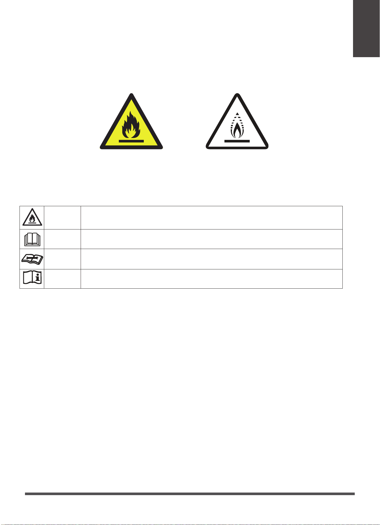
Caution: Risk of fire/
flammable materials
(Required for R32/R290 units only)
Warning: low burning
velocity material
(For R32 models apply to
IEC60335-2-40:2018)
precautions shall be complied with prior to conducting work on the system.
2)Work procedure
Work shall be undertaken under a controlled procedure so as to minimise the risk of a flammable gas
or vapour being present while the work is being performed.
6.Information on servicing
1)Checks to the area
Prior to beginning work on systems containing flammable refrigerants, safety checks are necessary to
ensure that the risk of ignition is minimised. For repair to the refrigerating system, the following
1.Transport of equipment containing flammable refrigerants
See transport regulations
2.M arking of equipment using signs
See local regulations
3.Disposal of equipment using flammable refrigerants
See national regulations.
4.Storage of equipment/ appliances
The storage of equipment should be in accordance with the manufacturer's instructions.
5.Storage of packed (unsold) equipment
Storage package protection should be constructed such that mechanical damage to the equipment
inside the package will not cause a leak of the refrigerant charge. The maximum number of pieces of
equipment permitted to be stored together will be determined by local regulations.
Explanation of symbols displayed on the unit(For the unit adopts R32/R290 Refrigerant only):
WARNING
CAUTION
CAUTION
CAUTION
This symbol shows that this appliance used a flammable refrigerant. If the refrigerant
is leaked and exposed to an external ignition source, there is a risk of fire.
This symbol shows that the operation manual should be read carefully.
This symbol shows that a service personnel should be handling this equipment
with reference to the installation manual.
This symbol shows that information is available such as the operating manual or
installation manual.
AVERTISSEMENT
Ne pas utiliser de produits permettant d’accélérer le dégel ou de produits de nettoyage autres que
ceux recommandés par le fabricant.
L’appareil doit être entreposé dans un endroit sans source d’allumage fonctionnant en continu (par
exemple : flamme nue, appareil au gaz en marche ou radiateur électrique en marche).
Ne pas percer ni bruler.
Attention : les frigorigènes peuvent être inodores.
Safety
Precautions
Page 5

7)Ventilated area
Ensure that the area is in the open or that it is adequately ventilated before breaking into the system or
conducting any hot work. A degree of ventilation shall continue during the period that the work is carried
out. The ventilation should safely disperse any released refrigerant and preferably expel it externally into
the atmosphere.
Repair and maintenance to electrical components shall include initial safety checks and component
inspection procedures. If a fault exists that could compromise safety, then no electrical supply shall be
connected to the circuit until it is satisfactorily dealt with. If the fault cannot be corrected immediately
8)Checks to the refrigeration equipment
Where electrical components are being changed, they shall be fit for the purpose and to the correct
specification. At all times the manufacturer's maintenance and service guidelines shall be followed. If in
doubt consult the manufacturer's technical department for assistance. The following checks shall be
applied to installations using flammable refrigerants:
The charge size is in accordance with the room size within which the refrigerant containing parts are
installed;
The ventilation machinery and outlets are operating adequately and are not obstructed;
If an indirect refrigerating circuit is being used, the secondary circuit shall be checked for the presence
of refrigerant; Marking to the equipment continues to be visible and legible. Markings and signs that
are illegible shall be corrected;
Refrigeration pipe or components are installed in a position where they are unlikely to be exposed to
any substance which may corrode refrigerant containing components, unless the components are co
nstructed of materials which are inherently resistant to being corroded or are suitably protected against
being so corroded.
9)Checks to electrical devices
The area shall be checked with an appropriate refrigerant detector prior to and during work, to ensure
the technician is aware of potentially flammable atmospheres. Ensure that the leak detection
equipment being used is suitable for use with flammable refrigerants, i.e. non-sparking, adequately
sealed or intrinsically safe.
5)Presence of fire extinguisher
If any hot work is to be conducted on the refrigeration equipment or any associated parts, appropriate
fire extinguishing equipment shall be available to hand. Have a dry powder or CO2 fire extinguisher
adjacent to the charging area.
6)No ignition sources
No person carrying out work in relation to a refrigeration system which involves exposing any pipe
work that contains or has contained flammable refrigerant shall use any sources of ignition in such a
manner that it may lead to the risk of fire or explosion. All possible ignition sources, including cigarette
smoking, should be kept sufficiently far away from the site of installation, repairing, removing and
disposal, during which flammable refrigerant can possibly be released to the surrounding space. Prior
to work taking place, the area around the equipment is to be surveyed to make sure that there are no
flammable hazards or ignition risks. No Smoking signs shall be displayed.
3)General work area
All maintenance staff and others working in the local area shall be instructed on the nature of work
being carried out. Work in confined spaces shall be avoided. The area around the workspace shall
be sectioned off. Ensure that the conditions within the area have been made safe by control of
flammable material.
4)Checking for presence of refrigerant
Work shall be undertaken under a controlled procedure so as to minimise the risk of a flammable
gas or vapour being present while the work is being performed.
Safety
Precautions
Page 6

Do not apply any permanent inductive or capacitance loads to the circuit without ensuring that this will
not exceed the permissible voltage and current permitted for the equipment in use. Intrinsically safe
components are the only types that can be worked on while live in the presence of a flammable
atmosphere. The test apparatus shall be at the correct rating. Replace components only with parts
specified by the manufacturer. Other parts may result in the ignition of refrigerant in the atmosphere
from a leak.
8.Repair to intrinsically safe components
and shall be calibrated to the refrigerant employed and the appropriate percentage of gas (25 %
maximum) is confirmed. Leak detection fluids are suitable for use with most refrigerants but the use of
detergents containing chlorine shall be avoided as the chlorine may react with the refrigerant and
corrode the copper pipe-work. If a leak is suspected, all naked flames shall be removed/ extinguished.
If a leakage of refrigerant is found which requires brazing, all of the refrigerant shall be recovered from
the system, or isolated (by means of shut off valves) in a part of the system remote from the leak.
Oxygen free nitrogen (OFN) shall then be purged through the system both before and during the
brazing process.
10.Detection of flammable refrigerants
The following leak detection methods are deemed acceptable for systems containing flammable
refrigerants. Electronic leak detectors shall be used to detect flammable refrigerants, but the sensitivity
may not be adequate, or may need re-calibration. (Detection equipment shall be calibrated in a
refrigerant-free area.) Ensure that the detector is not a potential source of ignition and is suitable for
the refrigerant used. Leak detection equipment shall be set at a percentage of the LFL of the refrigerant
11.Leak detection methods
Check that cabling will not be subject to wear, corrosion, excessive pressure, vibration, sharp edges or
any other adverse environmental effects. The check shall also take into account the effects of aging or
continual vibration from sources such as compressors or fans.
9.Cabling
Under no circumstances shall potential sources of ignition be used in the searching for or detection of
refrigerant leaks. A halide torch (or any other detector using a naked flame) shall not be used.
7.Repairs to sealed components
1)During repairs to sealed components, all electrical supplies shall be disconnected from the equipment
being worked upon prior to any removal of sealed covers, etc. If it is absolutely necessary to have an
electrical supply to equipment during servicing, then a permanently operating form of leak detection
shall be located at the most critical point to warn of a potentially hazardous situation.
2)Particular attention shall be paid to the following to ensure that by working on electrical components,
the casing is not altered in such a way that the level of protection is affected. This shall include damage
to cables, excessive number of connections, terminals not made to original specification, damage to
seals, incorrect fitting of glands, etc. Ensure that apparatus is mounted securely. Ensure that seals or
sealing materials have not degraded such that they no longer serve the purpose of preventing the
ingress of flammable atmospheres. Replacement parts shall be in accordance with the manufacturer's
specifications.
NOTE: The use of silicon sealant may inhibit the effectiveness of some types of leak detection equipment.
Intrinsically safe components do not have to be isolated prior to working on them.
but it is necessary to continue operation, an adequate temporary solution shall be used. This shall be
reported to the owner of the equipment so all parties are advised.
Initial safety checks shall include:
That capacitors are discharged: this shall be done in a safe manner to avoid possibility of sparking;
That there no live electrical components and wiring are exposed while charging, recovering or purging
the system; That there is continuity of earth bonding.
Safety
Precautions
Page 7

cylinders. (No more than 80 % volume liquid charge). i) Do not exceed the maximum working
pressure of thecylinder, even temporarily. j) When the cylinders have been filled correctly and the
process completed, make sure that the cylinders and the equipment are removed from site promptly
and all isolation valves on the equipment are closed off. k) Recovered refrigerant shall not be charged
into another refrigeration system unless it has been cleaned and checked.
15.Labelling
Equipment shall be labelled stating that it has been de-commissioned and emptied of refrigerant. The
label shall be dated and signed. Ensure that there are labels on the equipment stating the equipment
contains flammable refrigerant.
Before carrying out this procedure, it is essential that the technician is completely familiar with the
equipment and all its detail. It is recommended good practice that all refrigerants are recovered safely.
Prior to the task being carried out, an oil and refrigerant sample shall be taken in case analysis is
required prior to re-use of reclaimed refrigerant. It is essential that electrical power is available before
the task is commenced.
14.Decommissioning
a) Become familiar with the equipment and its operation. b) Isolate system electrically. c) Before
attempting the procedure ensure that: Mechanical handling equipment is available, if required, for
handling refrigerant cylinders;All personal protective equipment is available and being used correctly;
The recovery process is supervised at all times by a competent person; Recovery equipment and
cylinders conform to the appropriate standards. d) Pump down refrigerant system, if possible. e) If a
vacuum is not possible, make a manifold so that refrigerant can be removed from various parts of the
system. f) Make sure that cylinder is situated on the scales before recovery takes place. g) Start the
recovery machine and operate in accordance with manufacturer's instructions. h) Do not overfill
13.Charging procedures
In addition to conventional charging procedures, the following requirements shall be followed. Ensure
that contamination of different refrigerants does not occur when using charging equipment. Hoses or
lines shall be as short as possible to minimise the amount of refrigerant contained in them.
Cylinders shall be kept upright.
Ensure that the refrigeration system is earthed prior to charging the system with refrigerant.
Label the system when charging is complete (if not already).
Extreme care shall be taken not to overfill the refrigeration system. Prior to recharging the system it
shall be pressure tested with OFN. The system shall be leak tested on completion of charging but prior
to commissioning. A follow up leak test shall be carried out prior to leaving the site.
12.Removal and evacuation
When breaking into the refrigerant circuit to make repairs or for any other purpose conventional
procedures shall be used. However, it is important that best practice is followed since flammability is
a consideration. The following procedure shall be adhered to:
Remove refrigerant; Purge the circuit with inert gas; Evacuate; Purge again with inert gas; Open the
circuit by cutting or brazing.
The refrigerant charge shall be recovered into the correct recovery cylinders. The system shall be flu-
shed with OFN to render the unit safe. This process may need to be repeated several times. Comp-
ressed air or
oxygen shall not be used for this task.
Flushing shall be achieved by breaking the vacuum in the system with OFN and continuing to fill until
the working pressure is achieved, then venting to atmosphere, and finally pulling down to a vacuum.
This process shall be repeated until no refrigerant is within the system. When the final OFN charge is
used, the system shall be vented down to atmospheric pressure to enable work to take place. This
operation is absolutely vital if brazing operations on the pipe-work are to take place.
Ensure that the outlet for the vacuum pump is not close to any ignition sources and there is ventila-
tion available.
Safety
Precautions
Page 8
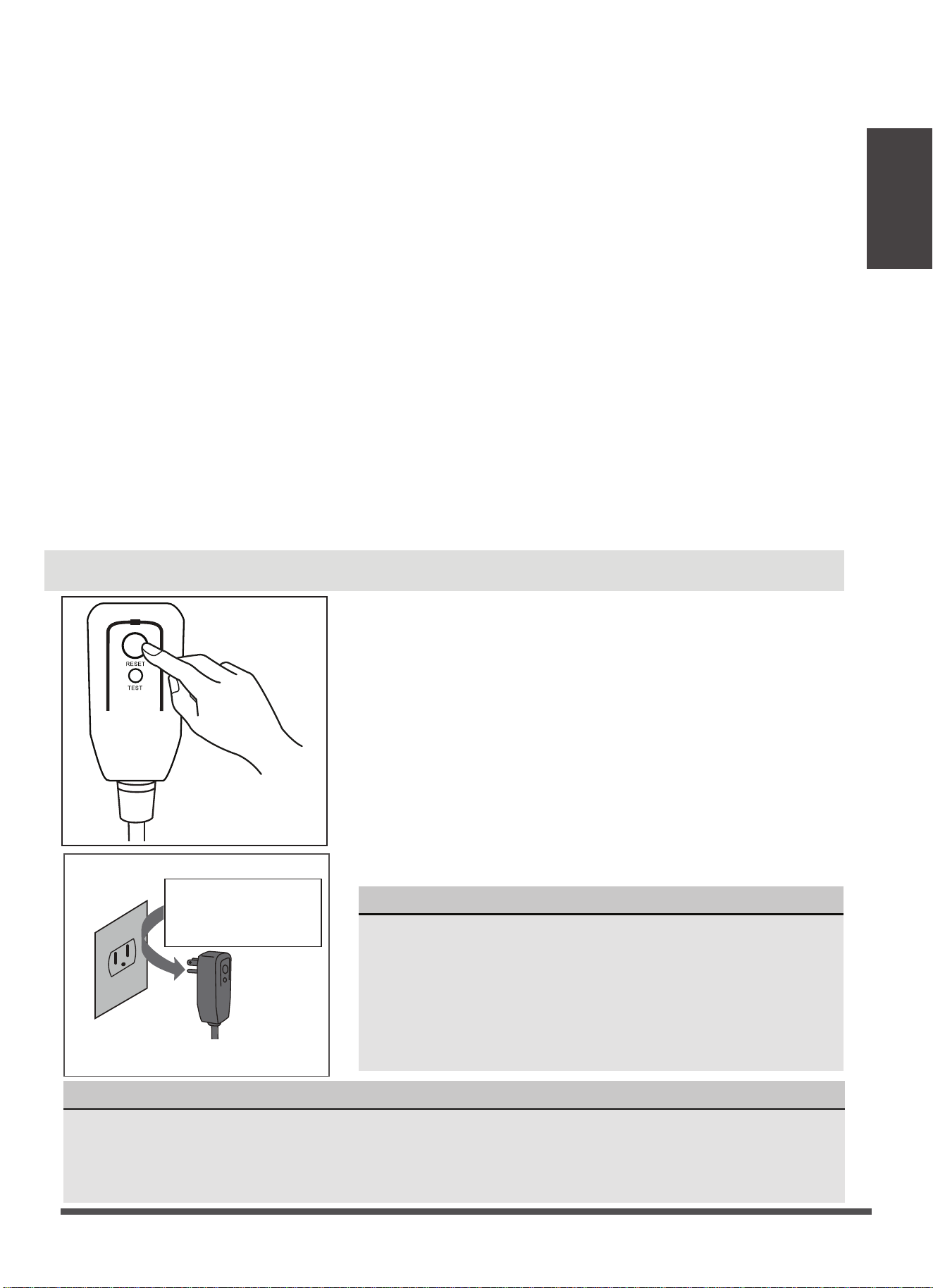
NOTICE
• Do not use this device to turn the unit on or off.
• Always make sure the RESET button is pushed in for correct operation.
• The power supply cord must be replaced if it fails to reset when either the TEST button is
pushed, or it can not be reset. Please contact Customer Service.
16.Recovery
When removing refrigerant from a system, either for servicing or decommissioning, it is recommended
good practice that all refrigerants are removed safely. When transferring refrigerant into cylinders, en-
sure that only appropriate refrigerant recovery cylinders are employed. Ensure that the correct number
of cylinders for holding the total system charge is available. All cylinders to be used are designated for
the recovered refrigerant and labelled for that refrigerant (i.e. special cylinders for the recovery of refr-
igerant). Cylinders shall be complete with pressure relief valve and associated shut-off valves in good
working order. Empty recovery cylinders are evacuated and, if possible, cooled before
recovery occurs.
The recovery equipment shall be in good working order with a set of instructions concerning the
equipment that is at hand and shall be suitable for the recovery of flammable refrigerants. In addition,
a set of calibrated weighing scales shall be available and in good working order. Hoses shall be com-
plete with leak-free disconnect couplings and in good condition. Before using the recovery machine,
check that it is in satisfactory working order, has been properly maintained and that any associated
electrical components are sealed to prevent ignition in the event of a refrigerant release. Consult
manufacturer if in doubt. The recovered refrigerant shall be returned to the refrigerant supplier in
the correct recovery cylinder, and the relevant Waste Transfer Note arranged. Do not mix refrigerants
in recovery units and especially not in cylinders. If compressors or compressor oils are to be removed,
ensure that they have been evacuated to an acceptable level to make certain that flammable refrig-
erant does not remain within the lubricant. The evacuation process shall be carried out prior to ret-
urning the compressor to the suppliers. Only electric heating to the compressor body shall be empl-
oyed to accelerate this process. When oil is drained from a system, it shall be carried out safely.
Operation of Current Device
The power supply cord contains a current measuring device
that detects damage to the power cord. Test your power
supply cord as follows:
1. Plug in the air conditioner.
2. The power supply cord will have TWO buttons on the
plug head. Press the TEST button. You will notice a click as
the RESET button pops out.
3. Press the RESET Button. You will notice a click as the
button engages.
4. The power supply cord is now supplying electricity to
the unit. (On some products this is also indicated by a light
on the plug head.)
NOTICE
The power supply cord with this air conditioner contains
a current detection device designed to reduce the risk of
fire.
In the event that the power supply cord is damaged, it
can not be repaired. It must be replaced with a cord from
the manufacturer
Grounding type wall receptacle
Do not, under any
circumstances, cut,
remove or bypass
the grounding prong.
Power supply cord with 3-prong grou-
nding plug and current detection device.
Plug in & press RESET
Page 9
Installation
Instructions
Page 10
Installation
Instructions
MODE Temperature Range MODE Temperature Range
Cool 16-35°C (60-95°F)
Dry
Heat(pump heat mode)
Heat(electrical heat mode) 13-35°C (55-95°F)
5-30°C (41-86°F)
30°C (86°F)
≥
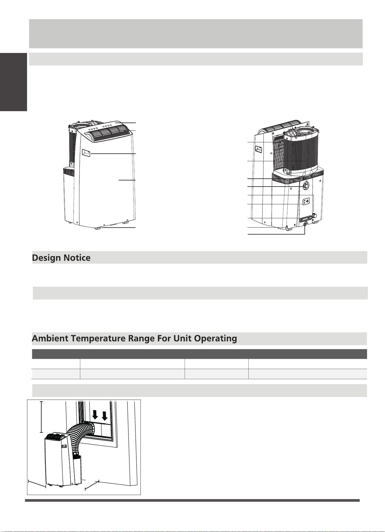
Choosing The Right Location
Your installation location should meet the following requirements:
-Make sure that you install your unit on an even surface to minimize noise
and vibration.
-The unit must be installed near a grounded plug, and the Collection Tray
Drain (found on the back of the unit) must be accessible.
-The unit should be located at least 25cm (9.8”) from the nearest wall to
ensure proper air conditioning. The horizontal louver blade should be at
least 50cm(19.7”) away from obstacles.
-DO NOT cover the Intakes, Outlets or Remote Signal Receptor of the unit,
as this could cause damage to the unit.
Installation Instructions
Preparation
NOTE:
All the illustrations in the manual are for explanation purpose only. Your machine may be slightly different.
The actual shape shall prevail. The unit can be controlled by the unit control panel alone or with the remote
controller. This manual does not include Remote Controller Operations, see the <<Remote Controller
Instruction>> packed with the unit for details.
In order to ensure the optimal performance of our products, the design specifications of the unit
and remote control are subject to change without prior notice.
rearfront
25 cm
9.8 inch
9.8 inch
25 cm
50 cm
19.7 inch
Exhaust Hose Installation
The exhaust hose and adaptor must be installed or removed in accordance with the usage mode. For
COOL,HEAT(heat pump type) or AUTO mode must be installed exhaust hose. For FAN, DRY or HEAT
(electrical heat type) mode must be removed exhaust hose.
Power plug storage
Power cord storage
Upper air filter
(behind the grille)
Inlet and outlet
air hose
Air inlet
Drain Outlet (dry mode)
Drain Outlet (heating mode)
Power cord outlet
Drain Outlet
(excess condensate)
Handle
(both sides)
Outlet louver
(automatic swing)
Caster
Control panel
Panel
Page 11
Installation
Instructions
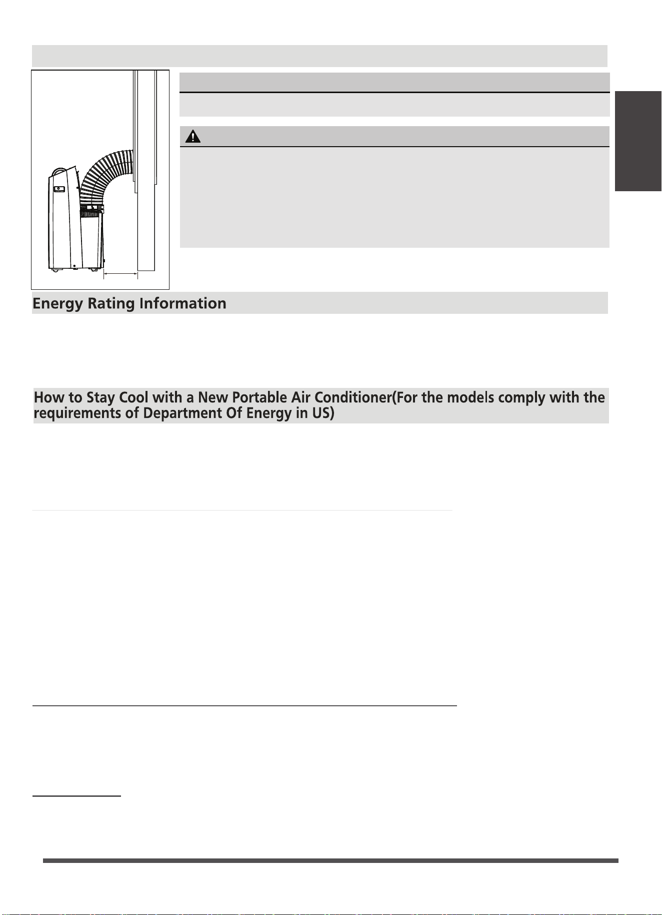
Recommend Installation
Mobile air conditioner with combined exhaust hose need the Exhuast Adaptor to test the condenser
inlet and outlet airflows. The Exhuast Adaptor must be provided by the manufacturer. The Exhuast
Adaptor connect the condenser inlet and outlet airflows to the airflow measuring instrument in
laboratory.
Because of a new federal test procedure for Portable Air Conditioners, you may notice that the
cooling capacity claims on portable air conditioner packaging are significantly lower than that of
models produced prior to 2017. This is due to changes in the test procedure, not to the portable
air conditioners themselves.
What should I look for first when purchasing a portable air conditioner?
The right air conditioner helps you cool a room efficiently. An undersized unit won't cool adequately
while one that's too large will not remove enough humidity, leaving the air feeling damp. To find
the proper air conditioner, determine the square footage of the room you want to cool by
multiplying the room length by its width. You also need to know the air conditioner's BTU (British
Thermal Unit) rating, which indicates the amount of heat it can remove from a room. A higher
Why is the cooling capacity lower on newer models than on older units?
number means more cooling power for a larger room. (Be sure you are comparing only newer
models to each other- older models may appear to have a higher capacity, but are actually the
same). Be sure to “size up” if your portable air conditioner will be placed in a very sunny room, in a
kitchen, or in a room with high ceilings. After you’ve found the right cooling capacity or your
room, you can look at other features.
Federal regulations require manufacturers to calculate cooling capacity based on a specific test
procedure, which was changed just this year. Models manufactured before 2017 were tested under
a different procedure and cooling capacity is measured differently than in prior years’models. So,
while the BTUs may be lower, the actual cooling capacity of the air conditioners has not changed.
What is SACC ?
SACC is the representative value of Seasonally Adjusted Cooling Capacity, in Btu/h, as determined
in accordance with the DOE test procedure at title 10 Code of Federal Regulations (CFR) 430,
subpart B, appendix CC and applicable sampling plans.
NOTICE
The appearance of your unit might be slightly different.
WARNING
•
This air-conditioning unit is a hermetically sealed unit that contains fluorinated
gasses. For specific information on the type of gas and the amount, please
refer to the relevant label on the unit itself.
Service, maintenance or repair of this unit must be performed by a certified
technician.
Product recycling must be done according to local regulations.
•
•
25 cm
9.8 inch
Page 12
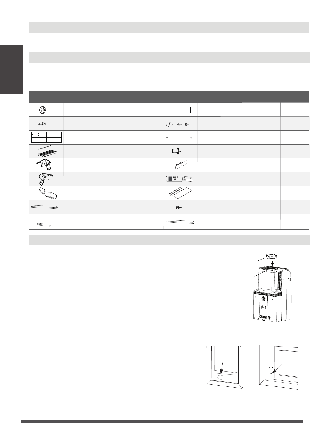
Tools Needed
-Philips screwdriver;
-Tape measure or ruler;
Installation
Instructions
Window Installation Kit
Accessories
NOTE: Your window Installation Kit fits windows 19.1’’-63.8’’(48.4-162cm). Please doublecheck all packaging
materials to make sure accessories do not get accidentally thrown away. Items with (*) are on some models.
Slight variations in design may occur.
-Knife or scissors;
-Saw (optional, to shorten window adaptor for narrow windows)
Air Exhaust Adapter
Exhaust Hose
1. For Hung Window types only
Insert the Air Exhaust Adapter into the exhaust of the hose
(the circular opening) for optimal performance. Rotate the
adapter clockwise until the locking tabs click and it no longer
rotates.
Skip this step if installing into a horizontal sliding window.
The Air Exhaust adapter may interfere with some window
screens, and can be removed if desired (Please note this
may slightly decrease performance).
Hung Window Sliding Window
Windows Type
Window slider
Window
slider
2. Preparing the adjustable w indow slider
1)
Depending on the size of your window, adjust the size of
the window slider.Use the combination of panels that best
fits your window opening.
2)
If the length of the window requires two or more window
sliders, use the bolt to fasten the window sliders once they
are adjusted to the proper length.
3)
If installing in a sliding window, bolts should be installed
on both sides of the window sliders.
Name of Accessories
Qty.
Shape
Name of Accessories
Qty.
Shape
1 pc(*)
1 pc(*)
1 pc
4 or 2pc
1 pc(*)
2-5 pc(*)
1 pc(*)
Foam Seal A (Adhesive)
Bolt
1 setSecurity Bracket and 2 Screws
1 pcDrain Hose
1 pc(*)
Power Cord Buckle
(only for cooling model)
ON /O FF
TEM P
SHO R T
CU T
TIME R
ON
TIME R
OFF
MO DE
FAN
SLE EP
SW ING
LED
1 set
Remote Controller and Battery
(only for remote control models)
1 - 8 pc
1 pc(*)
Drain Hose Adaptor
(only for heat pump model)
Air exhaust adapter
Window Sliders(model dependent)
Window Kit Brace
Sliding Window Adapter–Front
Sliding Window Adapter–Rear
Sliding Window Adapter–Air Divider
Foam Seal B (Adhesive)
Foam Seal C (Non-adhesive)
Window Slider Foam (adhesive) 2 pc(*)
Heat pump hose insulation foam
(optional)
1 set(*)
1 pc(*)1 Screw ( on Exhaust adaptor)
2 pc
2 or 1pc
Installation
Instructions
Page 13
3. Applying insulation to the w indow slider(For some units)
After assembling the window slider to your proper dimension, cut and apply the foam insu-
lation sheets to the exterior side of the window slider.
Window Slider Foam
Window
Slider Foam
NOTICE
Once the Exhaust Hose assembly and Adjustable Window Slider are prepared, choose from one of
the following two installation methods.
a
c
e
b
d
Three Window Sliders
with side holes
Two Window Sliders
without side hole
TYPE ONE
Use the table below to determine what
combinationof Window Sliders is correct
for your window
window slider
window dimension
(mm)
window dimension
(inch)
a+b 484 592 19.1 23.3
b+c 592 696 23.3 27.4
a+b+c 696
802 27.4 31.6
b+e 802 896 31.6 35.3
a+b+e 896 998 35.3 39.3
a+b+c+d 998 1210 39.3 47.6
1210 1620 47.6 63.8
a+b+c+d+e
~
~
~
~
~
~
~
~
~
~
~
~
~
~
Table 1(For some units)
a b c d e
boltboltbolt
Bolt
TYPE TWO
Three Window Sliders
with side holes
Two Window Sliders
without side hole
ba
Use the table below to determine what
combination of Window Sliders is correct
for your window
Table 2(For some units)
window slider
window dimension
(mm)
window dimension
(inch)
a+b 675 1245 26.8 49.0
~~
ab
Installation
Type 1: Hung w indow installation
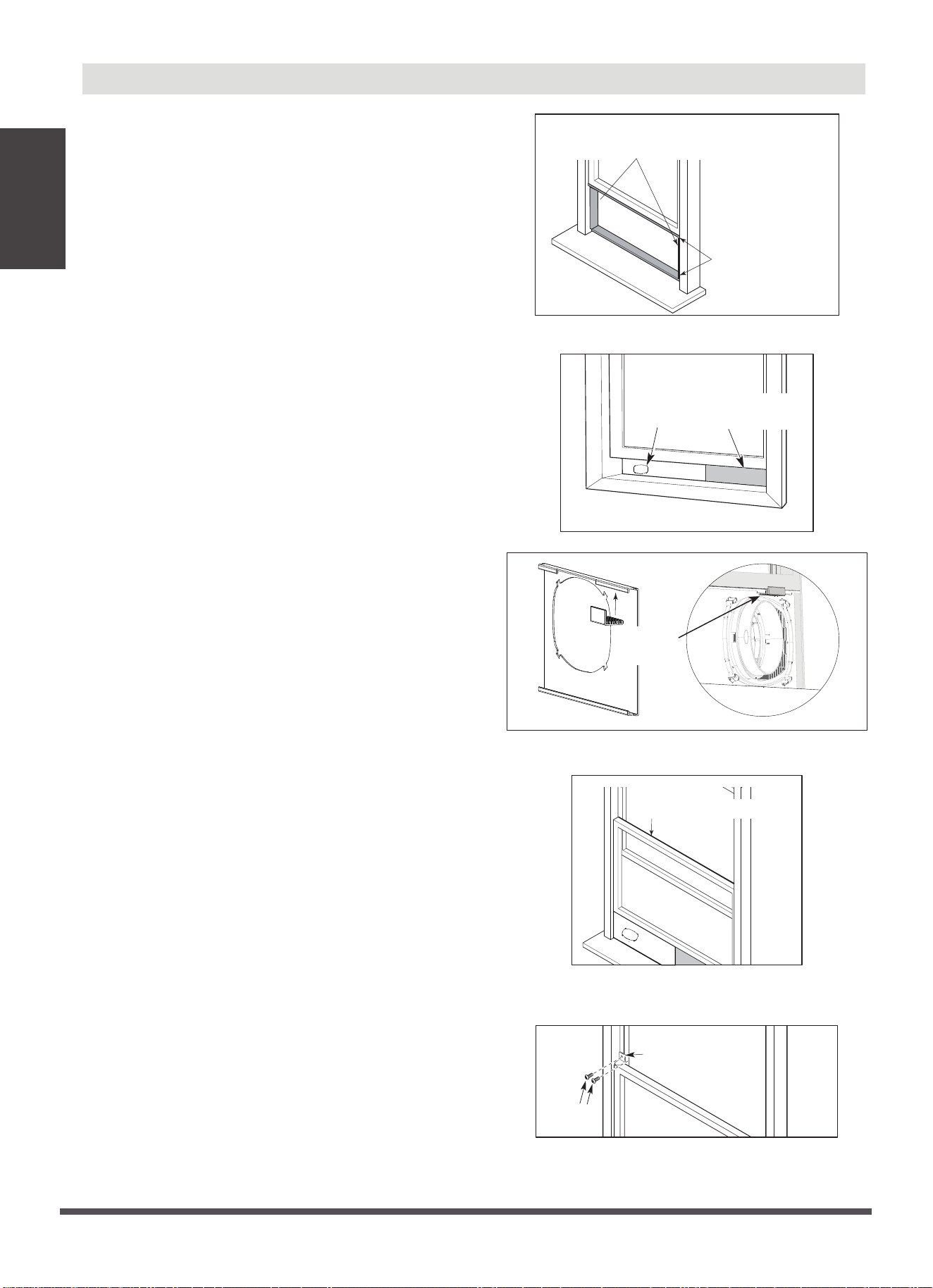
1. Cut the adhesive foam seal A and B strips to
the proper lengths, and attach them to the
window sash and frame as shown Fig.1.
Foam seal B
(Adhesive type-shorter)
Foam seal A
(Adhesive type)
Fig.1
2. Insert the window slider assembly into the
window track. If the hose opening is covered
by the lip of the window frame, rotate the
panel so the thicker side faces the window
frame.(see Fig.2)
For some units, attach the Window Kit Brace
to the back of the hose panel to brace against
the window so the window slider panels do
not lean inward. (see Fig.3)
3. Cut the non-adhesive foam seal C strip to
match the width of the window. Insert the
seal between the glass and the window
frame to prevent air and insects from getting
into the room.(see Fig.4)
4. If desired, install the security bracket with 2
screws as shown.(see Fig.5)
Window slider
(if required)
Window
slider
Fig.2
Window
Kit Brace
Fig.3
Foam seal C
(Non-adhesive type)
Fig.4
Security Bracket
2 Screws
Fig.5
Page 14
Installation
Instructions
5. Attach the hose to the window slider panel by
inserting the end of the hose into the opening
on the slider.(see Fig.6)
Fig.6
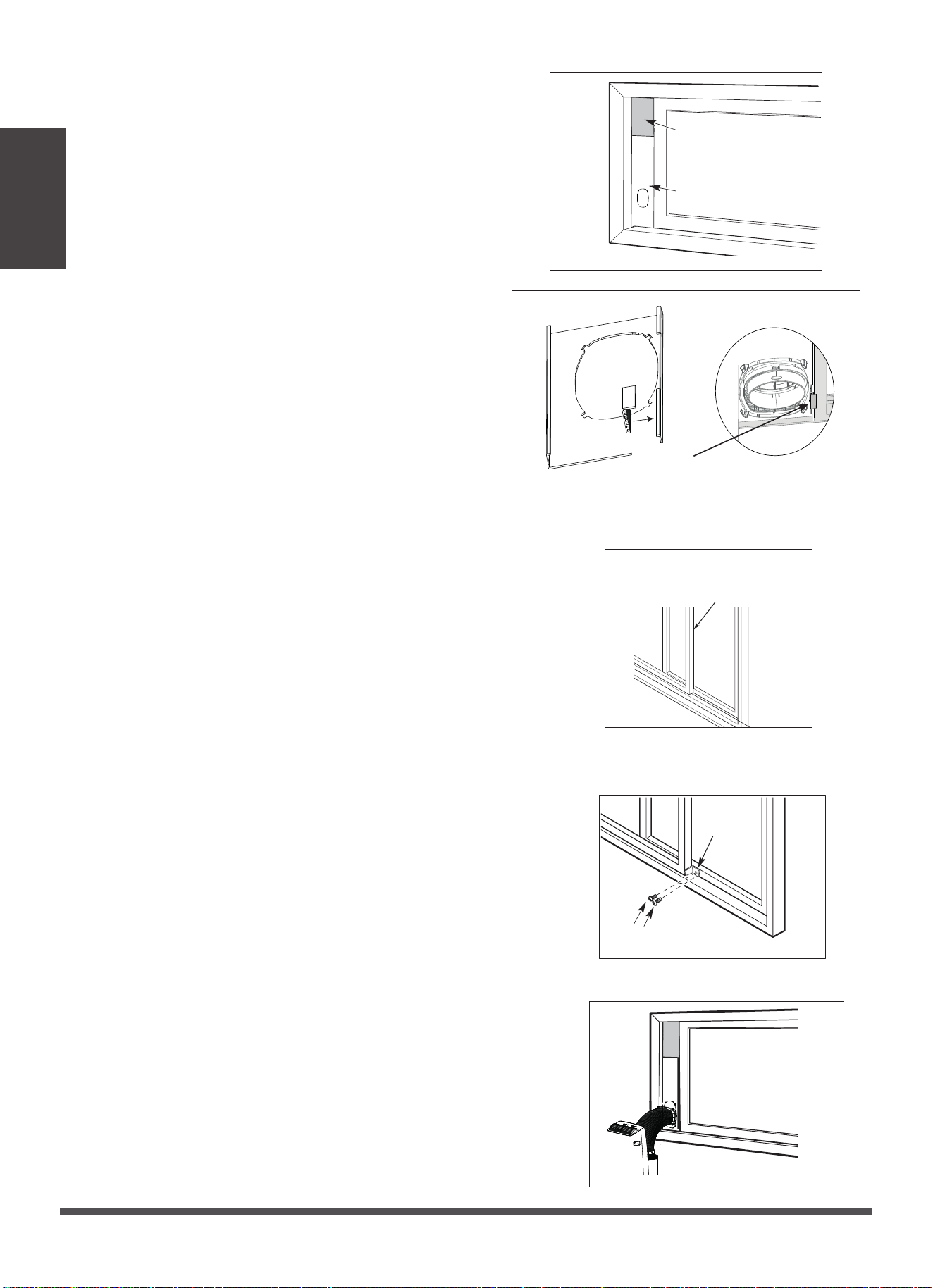
Type 2: Sliding w indow Installation (Optional)
1. Cut the adhesive foam seal A and B strips to
the proper lengths, and attach them to the
window sash and frame as shown.(see Fig.7)
Foam seal B
(Adhesive type-shorter)
Foam seal A
(Adhesive type)
Fig.7
2. Assembling the Sliding Window Adapter (Only
needed for Sliding Window applications):
Align both halves of the sliding window adapter
and connect them. Then, attach the air divider
to the newly formed window adapter on the
outdoor side. The fully assembled adapter
should look like the image at the left.(see Fig.8)
Sliding Window Adapter
(Front + Rear)
1 screw
Air Divider
Fig.8
Page 15
Installation
Instructions
3. Insert the window slider assembly into the
window track. If the hose opening is covered
by the window frame, rotate the panel so the
thicker side faces the window frame. (see Fig.9)
For some units, attach the Window Kit Brace
to the back of the hose panel to brace against
the window so the window slider panels do
not lean inward.(see Fig.10)
Window slider A
Window slider B
(if required)
Fig.9
Fig.10
Window
Kit Brace
4. Be sure bolts are installed in both sides of the
window slider for improved rigidity.
5. Cut the non-adhesive foam seal C strip to match
the window height. Insert the foam seal between
the glass and the window frame to prevent air
and insects from getting into the room.(see Fig.11)
Fig.11
Foam seal C
(Non-adhesive type)
6. If desired, install the security bracket with 2 screws
as shown.(see Fig.12)
2 Screws
Security
Bracket
Fig.12
7. Attach the Sliding Window Adapter to the hose by
lining up the circles on the adapter the hose. Insert
the window slider adapter into the hole of the window
slider.(see Fig.13)
Fig.13
Installation
Instructions
Page 16
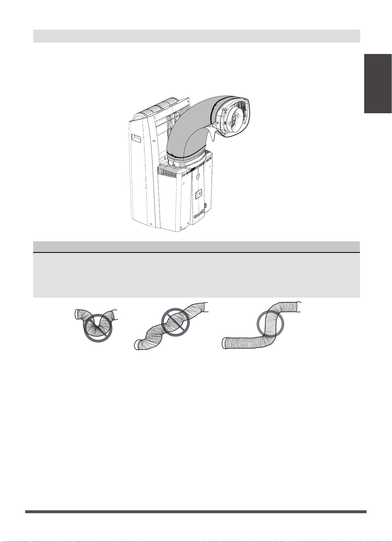
NOTICE
To ensure proper function, DO NOT overextend or bend the hose. Make sure that there
are no objects within 20in (~500mm) of the inlet and outlet hose. All illustrations in this
manual are for explanation purposes only, your air conditioner may be slightly different
than shown.
HEAT PUMP HOSE INSULATION FOAM(only for heat pump mode)
NOTE: When the unit is at heat mode, the heat pump hose insulation foam
must be fixed in the hose
of unit.
If you are experiencing condensation on the outer section of the hose during heating operation, apply
the included heat pump insulation foam to the outside of the hose. Use the included zip ties to secure
the foam around the hose.
Installation
Instructions
Page 17
Page 18
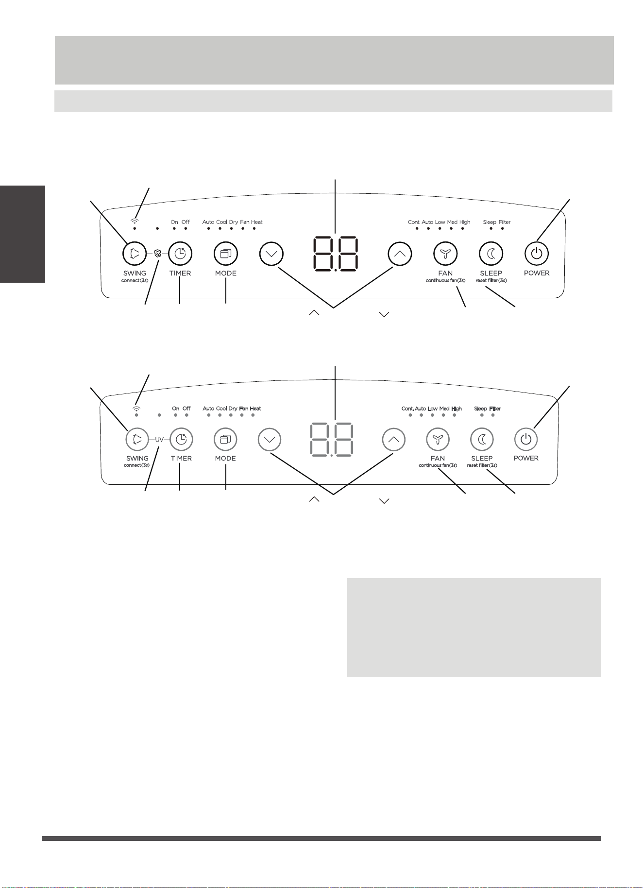
Timer Button
· Used to initiate the AUTO ON start time and AUTO
OFF stop time program. The timer on or off light will
illuminate depending on the selected setting.
Wireless connection feature(On some models)
· The swing button is also used to initiate the wir-
eless connection mode.
For the first time to initiate
the wireless connection mode, power on the air
conditioner then press the SWING button for 3
seconds. The LED DISPLAY will show ‘AP’ to indi-
cate the unit is in wireless connection mode.
Refer to the app connection instructions to finish
the connection process.If the connection is succ-
essful, the unit will exit wireless connection mode
and illuminate the wireless LED. If the connection
Sw ing Button
· Used to initiate the Auto Swing feature. When
the operation is ON, pressing the SWING button
can stop the louver at the desired angle.
Pow er Button
·
Powers the unit on and off.
Operating
Instructions
Operating Instructions
Control Panel Features
NOTE: The following control panels
are for explanation purpose only. The control panel of the unit you
purchased may be slightly different according to the models. Your machine may not contain some indicators
or buttons. The actual shape shall prevail.
Swing (Connect)
Button
Mode
Button
Power Button
Sleep
Button
Fan
Button
Timer
Button
LED Display
Wireless Indicator(Optional)
Air Magic
Up ( ) and Down ( )
Buttons
Air Magic
(Optional)
fails, the unit will exit wireless connection mode
automatically after 8 minutes and the wireless LED
does not illuminate.
NOTE: The wireless connection process must be
completed within 8 minutes after entering the
wireless connection mode.
When you restart the Wireless function,
it may take a period of time to connect to the
network automatically.
Swing (Connect)
Button
Mode
Button
Power Button
Sleep
Button
Fan
Button
Timer
Button
LED Display
Wireless Indicator(Optional)
Up ( ) and Down ( )
Buttons
UV light
(Optional)

UV feature(on some models)
·
Press SWING button and TIME button at the
same time for 3 seconds to initiate UV-C lamp
feature and the UV light illumiantes, the LED
DISPLAY shows 'On' for 3 seconds for some
units. The UV-C lamp feature will help to
purify the air inside. Press it for 3 seconds
again to stop the UV-C lamp feature and the
UV light turn dark, the LED DISPLAY shows
'OF' for 3 seconds for some units.
Up ( ) and Dow n ( ) Buttons
· Used to increase/decrease temperature settings in
1° increments in a range of 60°F/16°C to 86°F/30°C
or the TIMER setting in a range of 0 ~ 24hrs.
· To change between °F or °C, simultaneously press
and hold the Up and Down buttons for 3 seconds.
M ode Button
· Selects the desired operating mode. Each time you
press the button, a mode is selected in a sequence
that goes from AUTO, COOL, DRY, FAN and HEAT
(Heat models only). The mode light illuminates and
indicates the selected mode.
· Controls the fan speed. Press to control the fan
speed in four steps - LOW, MID, HIGH and AUTO.
The selected fan speed light will illuminate.
NOTE: Applicable to models with the Constant
Fan feature. In COOL or DRY mode, press the Fan
button for 3 seconds to turn on or off the constant
fan function.
When the function is turned on, the constant fan
light will illuminate, indicating the fan will run
constantly. When the function is turned off, the
constant fan light will go out, indicating that the
fan will stop when the compressor stops.
Fan Button/ Continuous fan(On some models) button
Air M agicfeature(on some models)
·
Press SWING button and TIME button at
the same time for 3 seconds to initiate Air Magic
feature and the Air Magic light illumiantes, the
LED DISPLAY shows 'On' for 3 seconds for some
units. Press it for 3 seconds again to stop the
Air Magic feature and the Air Magic light turn
dark, the LED DISPLAY shows 'OF' for 3 seconds
for some units.
Sleep Button
·
Used to initiate the SLEEP operation.
·
Pressing this button will increase (during
cooling operation) or decrease (during heating
operation, applicable models) 2°F/1°C after 30
minutes. The temperature will again increase
(cooling) or decrease (heating) by another
2°F/1°C after an additional 30 minutes. This
new temperature will be maintained for 7
hours before returning to the originally sele-
cted temperature. This ends the Sleep mode
and the unit will continue to operate as orig-
inally programmed.
·
Press SLEEP button
for 3 seconds
to initiate
the filter feature.This feature is a reminder to
clean the Air Filter for more efficient operation.
The LED(the light above the button) will illumi-
nate after 250 hours of operation.
LED Display
·
Shows the set temperature in °F (Degrees
Fahrenheit)("°F" no display for some models)
or °C (Degrees Celsius) and the Auto-timer
settings. While on DRY and FAN modes, it
shows the room temperature.
·
Shows Error codes and protection code:
The unit may stop operation or continue to
run safely. If the error codes appear, wait for
about 10 minutes. The problem may resolve
itself. If not, disconnect the power, then
connect it again. Turn the unit on. If the
problem persists, disconnect the power and
contact your nearest customer service center.
Error code appears andbegins with the
letters as the following in the window
display of indoor unit:EH(xx), EL(xx), EC(xx),
PH(xx), PL(xx), PC(xx)
P1-Bottom tray is full--Connect the drain hose
and drain the collected water away.If protection
repeats,call for service.
Note: When one of the above malfunctions
occurs, turn off the unit, and check for any
obstructions. Restart the unit, if the malfunction
is still present, turn off the unit and unplug the
power cord. Contact the manufacturer or its
service agents or a similar qualified person for
service.
Operating
Instructions
Page 19

Other features
TEM P SENSING feature(On some models)
NOTE:This feature can be activated from the remote
control ONLY. There is no indicator light on the
control panel. The remote control serves as a remote
thermostat allowing for the precise temperature
control at its location.
To activate the Temp Sensing feature, point the rem-
ote control towards the unit and press the I SENSE
button. The remote control will send this signal to the
Operation Instructions
COOL operation
· Press the "MODE" button until the "COOL"
indicator light comes on.
· Press the ADJUST buttons "UP" or "DOWN" to
select your desired room temperature. The temp-
erature can be set within a range of
16°C/60°F to
30°C/86°F
.
· Press the "FAN SPEED" button to choose the fan
speed.
HEAT operation(cooling only models w ithout)
· Press the "MODE" button until the "HEAT"
indicator light comes on.
· Press the ADJUST buttons "UP" or " DOWN" to
select your desired room temperature. The tempe-
rature can be set within a range of
16°C/60°F to
30°C/86°F
.
· Press the "FAN SPEED" button to choose the fan
speed.
DRY operation
· Press the "MODE" button until the "DRY" indi-
cator light comes on.
· Under this mode, you cannot select a fan speed.
The fan motor operates at AUTO speed.
· Keep windows and doors closed for the best de-
humidifying effect.
TIM ER operation
· When the unit is on, press the Timer button will
initiate the Auto-off stop program, the TIMER OFF
indicator light illuminates. Press the UP or down
button to select the desired time. Press the TIMER
button again within 5 seconds, the Auto-on start
program is initiated. And the TIMER ON indicator
light illuminates. Press the up or down button to
select the desired Auto-on start time.
· When the unit is off, press the Timer button to
initiate the Auto-on start program, press it again
within 5 seconds will initiate the Auto-off stop
program.
· Press or hold the UP or DOWN button to change
the Auto time by 0.5 hour increments, up to 10
hours, then at 1 hour increments up to 24 hours.
The control will count down the time remaining
until start.
· The system will automatically revert back to
display the previous temperature setting if there is
no operation in a 5 seconds period.
· Turning the unit ON or OFF at any time or adju-
sting the timer setting to 0.0 will cancel the Auto
Start/Stop timer program.
AUTO operation
· When you set the air conditioner in AUTO mode,
it will automatically select cooling, heating(cooling
only models without), or fan only operation depen-
ding on what temperature you have selected and
the room temperature.
· The air conditioner will control room temperature
automatically round the temperature point set by you.
· Under AUTO mode, you can not select the fan
speed.
Operating
Instructions
FAN operation
· Press the "MODE" button until the"FAN " indi-
cator light comes on.
· Press the "FAN SPEED" button to choose the fan
speed. The temperature can not be adjusted.
air conditioner until press the I SENSE button again.
If the unit
does not receive the Temp Sensing signal
during any 7 minutes interval, the unit will exit the
Temp Sensing mode.
NOTE: This feature is unavailabe under FAN or DRY
mode.
Page 20
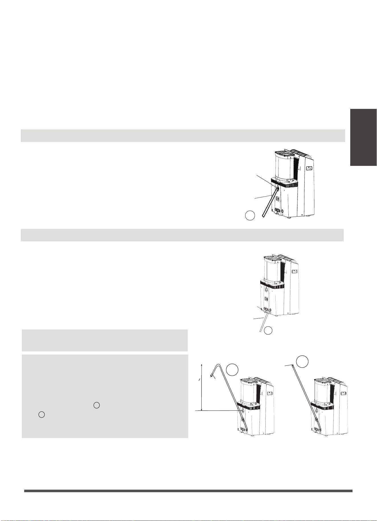
Water drainage(For Heating Mode)
Note: Make sure the drain hose is lower than the
bottom tray drain outlet.
that there are no kinks that will stop the warter flowing.
Place the end of the hose into the drain and make sure
the end of the hose is down to let the water flow
smoothly.(See Figs with . Do never let it up.(See Figs
with ). When the continuous drain hose is not used,
ensure that the corresponding drain plug and knob
are installed firmly to prevent leakage.
NOTE: Make sure the hose is secure so there are no
leaks. Direct the hose toward the drain, making sure
√
X
drain hose
adaptor
√
delivery lift <1.8m
X
drain hose
adaptor
Continuous
drain hose
Remove the
lower drain plug
√
· While operating in heat pump mode, the unit will
produce condensate that must be drained. You must
install the drain hose when operating in heat mode. To
install the drain hose, remove the plug from the drain
port and attach the included hose. The universal drain
adaptor can be attached to the end of the included
hose. A 3/4” hose (not included) can be attached to
the adaptor if a longer hose length is required. Place
the end of the hose in the drain area you are using.
Water drainage
· During dehumidifying modes, remove the upper drain plug from
the back of the unit, install the drain hose. For the models without
drain connector, just attach the drain hose to the hole. Place the
open end of the hose directly over the drain area in your basement
floor.
Remove the
upper drain plug
√
Continuous
drain hose
WAIT 3 M INUTES BEFORE RESUM ING OPERATION
After the unit has stopped, it can not be restarted
operation in the first 3 minutes. This is to protect the
unit. Operation will automatically start after 3 minutes.
AIR FLOW DIRECTION ADJUSTM ENT
The louver can be adjusted automatically. Adjust the
air flow direction automatically:
· When the Power is ON, the louver opens fully.
· Press the SWING button on the panel or remote
controller to initiate the Auto swing feature. The
louver willl swing up and down automatically.
· Please do not adjust the louver manually.
AUTO-RESTART
If the unit breaks off unexpectedly due to the power
cut, it will restart with the previous function setting
automatically when the power resumes.
Operating
Instructions
Page 21
Operating
Instructions
· When the water level of the bottom tray reaches a prede-
termined level, the unit beeps 8 times, the digital display
area shows "P1" . At this time the air conditioning/dehum-
idification process will immediately stop. However, the fan
motor will continue to operate(this is normal). Carefully
move the unit to a drain location, remove the bottom drain
plug and let the water drain away. Reinstall the bottom drain
plug and restart the machine until the "P1" symbol disappears.
If the error repeats, call for service.
NOTE: Be sure to reinstall the bottom drain plug firmly to
prevent leakage before using the unit.
Page 22
Maintenance
Safety Precautions
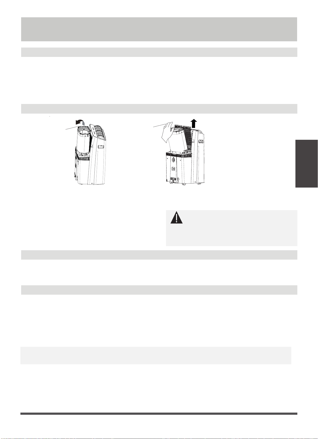
Air Filter Cleaning
Unit Cleaning
Store the unit when not in use
Maintenance
· Always unplug the unit before cleaning or servicing.
· DO NOT use flammable liquids or chemicals to clean the unit.
· DO NOT wash the unit under running water. Doing so causes electrical danger.
· DO NOT operate the machine if the power supply was damaged during cleaning. A damaged
power cord must be replaced with a new cord from the manufacturer.
CAUTION
DO NOT operate the unit without filter
because dirt and lint will clog it and reduce
performance.
Maintenance Tips
· Be sure to clean the air filter every 2 weeks for
optimal performance.
· The water collection tray should be drained
immediately after P1 error occurs, and before
storage to prevent mold.
· In households with animals, you will have to
periodically wipe down the grill to prevent
blocked airflow due to animal hair.
Clean the unit using a damp, lint-free cloth and mild detergent. Dry the unit with a dry, lint-free
cloth.
· Drain the unit’s water collection tray according to the instructions in the following section.
· Run the appliance on FAN mode for 12 hours in a warm room to dry it and prevent mold.
· Turn off the appliance and unplug it.
· Clean the air filter according to the instructions in the previous section. Reinstall the clean,
dry filter before storing.
· Remove the batteries from the remote control.
Note: Be sure to store the unit in a cool, dark place. Exposure to direct sunshine or extreme
heat can shorten the lifespan of the unit.
Hold and push backward
slightly, then lift it up
Upper filter
(take out)
Note: The cabinet and front may be dusted with an oil-free cloth or washed with a cloth da-
mpened in a solution of warm water and mildliquid dishwashing detergent. Rinse thoroughly
and wipe dry. Never use harsh cleansers, wax or polish on the cabinet front. Be sure to wring
excess water from the cloth before wiping around the controls. Excess water in or around the
controls may cause damage to the unit.
Page 23

Troubleshooting
Tips
Troubleshooting Tips
Problem Possible Causes Solution
Unit does not turn
on when pressing
ON/OFF button
P1 Protection Code
In COOL mode: room
temperature is lower than
the set temperature
Reset the temperature
The Water Collection Tray is full. Turn off the
unit, drain the water from the Water Collection
Tray and restart the unit.
The air filter is blocked with
dust or animal hair
The unit is low on
refrigerant
Temperature setting is too
high
The windows and doors in
the room are open
The room area is too large
Unit does not cool
well
Exhaust hose is not
connected or is blocked
There are heat sources
inside the room
Turn off the unit and clean the filter according
to instructions
Call a service technician to inspect
the unit and top off refrigerant
Decrease the set temperature
Make sure all windows and doors are closed
Double-check the cooling area
Turn off the unit, disconnect the hose, check for
blockage and reconnect the hose
Remove the heat sources if
possible
The unit is noisy
and vibrates too
much
The unit makes a
gurgling sound
The ground is not level Place the unit on a flat, level surface
The air filter is blocked with
dust or animal hair
Turn off the unit and clean the filter according
to instructions
This sound is caused by the
flow of refrigerant inside
the unit
This is normal
Page 24


CP001UI-PTTY
16120600001190
20220824
The design and specifications are subject to change without prior notice for
product improvement. Consult with the sales agency or manufacturer for details.
Any updates to the manual will be uploaded to the service website, please check
for the latest version.

此面及后面的页面无需印刷
技术 要求:
1.80g双胶纸
2.尺寸:A4 210*290
3.颜色:黑白
4.注意:排版时注意页码数字都是靠外面的,以便翻阅
5.装订。
,
备注:
1. 基准说明书只适合北美PT平台所有常规安装方式机型。
2. 基准说明书为单英文版本,不含型号及商标,也无制造商信息,请业务根据所
销售国家或者区域的法规要求,使用对应的官方语言版本,增加型号及其它
法规要求信息,重新申请订单编码说明书。
3. 基准说明书的显示标贴为北美PT全功能,包含了目前已有的所有图标和功能按键及其
操作说明,请业务和技术支持根据订单实际的显示标贴对说明书的显示标贴进行替换,
对图标和功能及其说明进行相应 删减。
4. 后面的选配页面标明了对应的不同冷媒(可燃冷媒与非可燃冷媒)下要修改的内容。

当机型为非可燃冷媒机型时,请进行以下变更:
删除Pg5-Pg9(WARNING for Using R32/R290 Refrigerant)内容。
设计变更流程-N11143844 PT市场问题改善
1.增加选配UV功能,P3增加对应UV灯安规内容,P18增加UV功能显示标贴,并增加对应说明标准;
2.按照美国分公司客牌说明书对应修改排风管安装部分内容以及增加选配五块排风管内容,
具体页数P10-P17;
3.P9页按照美国分公司客牌说明书版本增加电源线规格内容;