Loading ...
Loading ...
Loading ...

9
Step 4
Attach the safety wire to the mounting chassis
as shown in the following drawing.
Step 5
Insert the anchor bolt (for securing the mount-
ing chassis) into the mounting hole of the
mounting chassis.
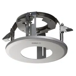
To adjust the position of the i-PRO logo on the
decorative cover, rotate the mounting chas-sis.
Note that the i-PRO logo will be located
at approximately 180 ° opposite side of a hook
for the decorative cover.
Safety wire
(Accessory)
Roof space
Ceiling board
Cables
Pass the loop
through the
tip of the
safety wire.
Mounting
chassis
Mounting hole
Approx. 10 °
Direction of brand logo
Hooks (x3)
Step 6
Secure the mounting chassis to the ceiling
board with the ceiling board fixing screws (4
positions).
Turning the ceiling board fixing screws clock-
wise provides ceiling board tightening between
the bottom of the mounting chassis and ceiling
board fixing bracket resulting in mounting chas-
sis securing.
(Recom mended tightening torque:
0.78 N·m {0.58 lbf·ft})
IMPORTANT:
When securing this bracket on the ceiling,•
make sure that the four ceiling board fixing
brackets are open as shown in the following
figure.
Step 7
Use double nuts (locally procured) to secure
the mounting chassis after inserting the anchor
bolt (for securing the mounting chassis).
Anchor bolt
(for securing the mounting chassis)
Ceiling board
fixing screw
Ceiling board
fixing bracket
Turn clockwise
Double nuts
(locally procured)
Ceiling board
Anchor bolt
(for connecting the safety wire)
Loading ...
Loading ...
Loading ...