

18V 3AH Ø115MM CORDLESS ANGLE GRINDER
MODEL NO’S: CP401LI CP401LIHV
Thank you for purchasing a Sealey product. Manufactured to a high standard, this product will, if used according to these instructions,
and properly maintained, give you years of trouble free performance.
IMPORTANT: PLEASE READ THESE INSTRUCTIONS CAREFULLY. NOTE THE SAFE OPERATIONAL REQUIREMENTS, WARNINGS & CAUTIONS. USE
THE PRODUCT CORRECTLY AND WITH CARE FOR THE PURPOSE FOR WHICH IT IS INTENDED. FAILURE TO DO SO MAY CAUSE DAMAGE AND/OR
PERSONAL INJURY AND WILL INVALIDATE THE WARRANTY. KEEP THESE INSTRUCTIONS SAFE FOR FUTURE USE.
1. SAFETY
WARNING! Read all safety warnings, instructions, illustrations and specications provided with this power tool. Failure to follow all
instructions listed below may result in electric shock, re and/or serious injury.
9 Save all warning and instructions for future reference.
1.1. WORK AREA SAFETY
9 Keep work area clean and well lit. Cluttered or dark areas invite accidents.
8 DO NOT operate power tools in explosive atmospheres, such as in the presence of ammable liquids, gases or dust. Power tools
create sparks which may ignite the dust or fumes.
9 Keep children and bystanders away whilst operating a power tool. Distractions can cause you to lose control.
9 Keep bystanders a safe distance away from work area. Anyone entering the work area must wear personal protective equipment.
Fragments of workpiece or of a broken accessory may y away and cause injury beyond immediate area of operation.
8 DO NOT operate the power tool near ammable materials. Sparks could ignite these materials.
1.2. ELECTRICAL SAFETY
9 Power tool plugs must match the outlet. Never modify the plug in any way. DO NOT use any adaptor plugs with earthed (grounded)
power tools. Unmodied plugs and matching outlets will reduce risk of electric shock.
9 Avoid body contact with earthed or grounded surfaces, such as pipes, radiators, ranges and refrigerators. There is an increased risk of
electric shock if your body is earthed or grounded.
8 DO NOT expose power tools to rain or wet conditions. Water entering a power tool will increase the risk of electric shock.
8 DO NOT abuse the cord. Never use the cord for carrying, pulling, or unplugging the power tool. Keep cord away from the heat, oil,
sharp edges or moving parts. Damaged or entangled cords increase the risk of electric shock. (If applicable).
9 When operating a power tool outdoors, use an extension cord suitable for outdoor use. Use of a cord suitable for outdoor use reduces
the risk of electric shock.
9 If operating a power tool in a damp location is unavoidable, use a residual current device (RCD) protected supply. Use of an RCD
reduces the risk of electric shock.
9 Hold the power tool by insulated gripping surfaces only, when performing an operation where the cutting accessory may contact hidden
wiring. Cutting accessory contacting a “live” wire may make exposed metal parts of the power tool “live” and could give the operator an
electric shock.
1.3. PERSONAL SAFETY
9 Stay alert, watch what you are doing and use common sense when operating a power tool.
8 DO NOT use a power tool whilst you are tired or under the inuence of drugs, alcohol, or medication. A moment inattention whilst
operating power tools may result in serious injury.
9 Use personal protective equipment. Always wear eye protection. Protective equipment such as dust mask, non-skid safety shoes, hard
hat or hearing protection used for appropriate conditions will reduce personal injuries.
9 Prevent unintentional starting. Ensure the switch is in the o-position before connecting to a battery pack, picking up or carrying the
tool. Carrying power tools with your ngers on the switch or energising power tools that have the switch on invites accidents.
9 Remove any adjusting key or wrench before turning the power tool on. A wrench or a key left attached to a rotating part of the power
tool may result in personal injury.
8 DO NOT overreach. Keep proper footing and balance at all times. This enables better control of the power tool in unexpected situations.
8 DO NOT let familiarity gained from frequent use of tools allow you to become complacent and ignore tool safety principles. A careless
action can cause severe injury within a fraction of a second.
9 Wear personal protective equipment. Depending on application, use face shield, safety goggles or safety glasses. As appropriate,
wear dust mask, hearing protectors, gloves and workshop apron capable of stopping small abrasive or workpiece fragments. The eye
protection must be capable of stopping ying debris generated by various applications. The dust mask or respirator must be capable of
ltrating particles generated by the particular application. Prolonged exposure to intense noise may cause hearing loss.
8 DO NOT run the power tool while carrying it at your side. Accidental contact with the spinning accessory could snag your clothing,
pulling the accessory into your body.
9 Dress properly. DO NOT wear loose clothing or jewellery. Keep your hair, clothing and gloves away from moving parts. Loose clothes,
jewellery or long hair can be caught in moving parts.
9 NEVER lay the power tool down until the accessory has come to a complete stop. The spinning accessory may grab the surface and
pull the power tool out of your control.
1.4. POWER TOOL USE & CARE
8 DO NOT force the power tool. Use the correct power tool for your application. The correct power tool will do the job better and safer at
the rate for which it was designed.
CP401LI CP401LIHV Issue 1 09/08/24
Original Language Version
© Jack Sealey Limited
Refer to
instructions
Wear eye
protection
Wear protective
gloves
Wear ear
protection
Wear a mask

8 DO NOT use the power tool if the switch does not turn it on and o. Any power tool that cannot be controlled with the switch is
dangerous and must be repaired.
WARNING! Never use your angle grinder without eye protection. Following this rule will reduce the risk of serious personal injury.
9 Disconnect the battery pack from the power tool before making any adjustments, changing accessories, or storing power tools. Such
preventive safety measures reduce the risk of starting the power tool accidentally.
9 Store idle power tools out of the reach of children and DO NOT allow persons unfamiliar with these power tools or these instructions to
operate the power tool. Power tools are dangerous in the hands of untrained users.
9 Maintain power tools. Check for misalignment or biding of the moving parts, breakage of parts and any other condition that may aect the
power tool’s operation. If damaged, have the power tool repaired before use. Many accidents are caused by poorly maintained power tools.
9 Keep cutting tools sharp and clean. Properly maintained cutting tools with sharp cutting edges are less likely to bind and are easier to control.
9 Use the power tool, accessories, and tool bits etc, in accordance with these instructions, taking into account the working conditions and
the work to be performed. Use of the power tool for operations dierent from those intended could results in a hazardous situation.
9 Keep handles and grasping surfaces dry, clean and free from oil and grease. Slippery handles and grasping surfaces do not allow for safe
handling and control of the tool in unexpected situations.
9 This power tool is intended to function as a grinder. Read all safety warnings, instructions, illustrations and specications provided with
this power tool. Failure to follow all instructions listed below may result in electric shock, re and/or serious injury.
9 Operations such as sanding, wire brushing or polishing are not recommended to be performed with this power tool. Operations for
which the power tool was not designed may create a hazard and cause personal injury.
8 DO NOT convert this power tool to operate in a way which is not specically designed and specied by the tool manufacturer. Such a
conversation may result in a loss of control and cause serious personal injury.
8 DO NOT use accessories which are not specically designed and recommended by the tool manufacturer. Just because the accessory
can be attached to your power tool, it does not assure safe operation.
9 The outside diameter and the thickness of your accessory must be within the capacity rating of your power tool. Incorrectly sized
accessories cannot be adequately guarded or controlled.
9 The rated speed of the accessory must be at least equal to the maximum speed marked on the power tool. Accessories running faster
than their rated speed can break and y apart.
9 The dimensions of the accessory mounting must t the dimensions of the mounting hardware of the power tool. Accessories that do not
match the mounting hardware of the power tool will run out of balance, vibrate excessively, and may cause loss of control.
9 Threaded mounting of accessories must match the grinder spindle thread. For accessories mounted by anges, the arbour hole of the
accessory must t the locating diameter of the ange. Accessories that DO NOT match the mounting hardware of the power tool will
run out of balance, vibrate excessively, and may cause loss of control.
8 DO NOT use a damaged accessory. Before each use inspect the accessory such as abrasive wheels for chips and cracks, backing
pad for cracks, tear or excess wear, wire brush for loose or cracked wires. If power tool or accessory is dropped, inspect for damage or
install an undamaged accessory.
NOTE: After inspecting and installing an accessory, position yourself and bystanders away from the plane of the rotating accessory and
run the power tool at maximum no-load speed for one minute. Damaged accessories will normally break apart during this test time.
8 DO NOT use accessories that require liquid coolants. Using water or other liquid coolants may result in electrocution or shock.
1.5. BATTERY TOOL USE & CARE
WARNING! Before inserting the battery pack, make sure that the on/o switch is in OFF position.
9 Depress the battery pack release button to release and slide the battery pack out from your tool. After recharge, slide it back into your
tool. A simple push and slight pressure will be sucient.
9 Recharge only with the charger specied by the manufacturer. A charger that is suitable for one type of battery pack may create a risk
of re when used with another battery pack.
9 Use power tools only with specically designated battery packs. Use of any other battery packs may create a risk of injury and re. When
battery pack is not in use, keep it away from other metal objects, like paper clips, coins, keys, nails, screws, or other small metal objects,
that can make a connection from one terminal to another. Shorting the battery terminals together may cause burns or a re.
9 Under abusive conditions, liquid may be ejected from the battery; avoid contact. If contact accidentally occurs, ush with water. If liquid
contacts eyes, additionally seek medical help. Liquid ejected from the battery may cause irritation or burns.
8 DO NOT use a battery pack or tool that is damaged or modied. Damaged or modied batteries may exhibit unpredictable behaviour
resulting in re, explosion or risk of injury.
8 DO NOT expose a battery pack or tool to re or excessive temperature. Exposure to re or temperature above 130°C may cause
explosion.
9 Follow all charging instructions and do not charge the battery pack or tool outside the temperature range specied in the instructions.
Charging improperly or at temperatures outside the specied range may damage the battery and increase the risk of re.
9 Longer life and better performance can be obtained if the battery pack is charged when the air temperature is between 18
o
C and 24
o
C.
8 DO NOT charge the battery pack in air temperatures below 0
o
C or above 40
o
C. This is important as it can prevent serious damage to
the battery back.
9 The battery pack is detachable. For replacement use CP400BP 18V 3Ah Lithium-ion battery.
1.6. NOISE & VIBRATION
9 The declared vibration total value(s) and the declared noise emission value(s) have been measured in accordance with a standard test
method and may be used for comparing one tool with another.
9 The declared vibration total values and the declared noise emission values may also be used in a preliminary assessment of exposure.
9 The vibration and noise emissions during actual use of the power tool can dier from the declared values depending on the ways in
which the tool is used, especially what kind of workpiece is processed.
9 The need to identify safety measures to protect the operator are to be based on an estimation of exposure in the actual condition of use.
CP401LI CP401LIHV Issue 1 09/08/24
Original Language Version
© Jack Sealey Limited
GREEN LIGHT RED LIGHT BATTERY ON THE CHARGER CHARGING STATUS
ON OFF NO Charger connected to power supply
OFF FLASHING YES Battery charging
ON OFF YES Battery fully charged
OFF ON YES Battery defective or bad contact
ON ON YES Battery too hot or too cold to be charged
CP401LI CP401LIHV Issue 1 09/08/24
Original Language Version
© Jack Sealey Limited
2. INTRODUCTION
Ø115mm cordless angle grinder supplied with 18V 3Ah Lithium-ion battery and a 2.4A mains charger in a storage case. Double
injection body with rubberised grips reduce vibration.
Two stage paddle switch allow for a natural holding position when in operation whilst maintaining safety. Quick and easy disc changes
using spindle lock button. Cast aluminium gear head with three mounting positions for secondary handle. Battery interchangeable with
our CP400LI & CP400LIHV impact wrenches.
3. SPECIFICATION
4. ASSEMBLY
4.1. ASSEMBLY AND ADJUSTING
WARNING! Before undertaking any work on the machine itself, remove the battery pack. Always disconnect your angle grinder
from the power source when replacing grinding or cut-o discs, adjusting the guard, cleaning the tool or when the tool is not in use.
Disconnecting the angle grinder will prevent accidental starting that could cause serious personal injury.
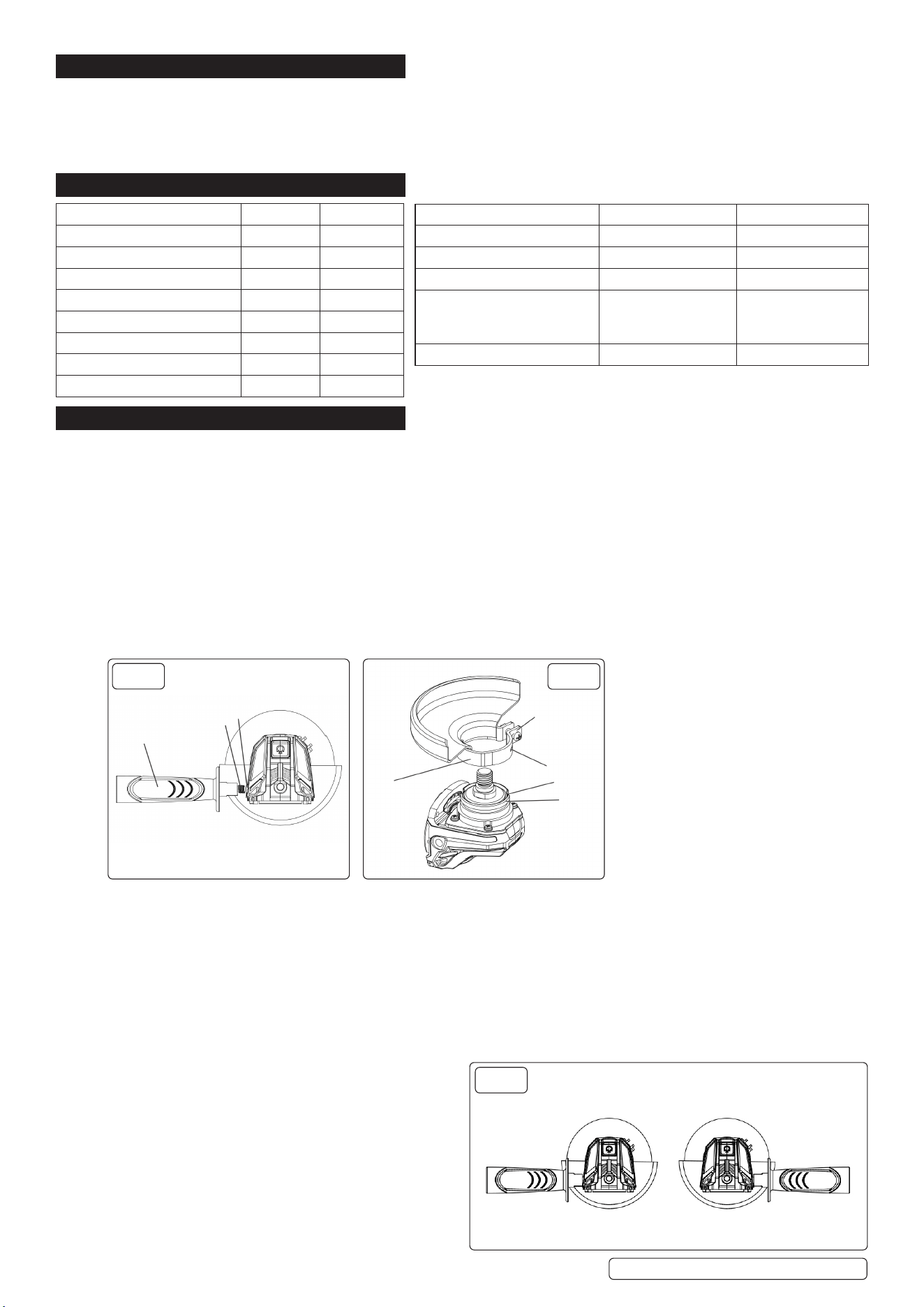
4.2. INSTALLING THE AUXILIARY HANDLE
Unplug the angle grinder from the power source. Install the auxiliary handle (1) by screwing it clockwise into the left side (2) of the gear
housing (3) (Fig.1).
NOTE: The handle can be installed in two dierent positions; left side or right side (Fig.3).
WARNING! The auxiliary handle must always be used to prevent loss of control and possible injury. Tighten the auxiliary handle
securely. NOTE: Hand tighten the auxiliary handle. DO NOT over tighten.
4.3. INSTALLING THE GUARD
WARNING! The guard must be installed before installing a grinding disc or using the angle grinder. Failure to do so could result in
serious personal injury.
4.3.1. Unscrew (1) outward to allow the guard clamp to expand for installation. Slide the guard clamp (2) over the spindle housing (3) until the
blade guard locating slots (4) line up with grooves (5) in the spindle housing (Fig. 2).
4.3.2. When using a dual purpose (Combined grinding and cutting-o abrasive) ange mounted wheels, instruction to only use either Type A
(cut-o) or Type C (Combination) wheel guard.
9 When using a Type A (Cut-o) wheel guard for facial grinding, the wheel guard may interfere with the workpiece causing poor control.
9 When using a Type B (Grinding) wheel guard for cutting-o operations with bonded abrasive wheels, there is an increased risk of
exposure to emitted sparks and particles, as well as exposure to wheel fragments in the event of wheel burst.
9 When using a Type A (Cut-o), Type B (Grinding) or Type C (Combination) wheel guard for cutting-o and facial operations in concrete
or masonry, there is an increased risk of exposure to dust and loss of control resulting in kickback.
9 When using a Type A (Cut-o), Type B (Grinding) or Type C (Combination) wheel guard with a wheel-type wire brush with a thickness
greater than the maximum thickness, as specied.
4.3.3. Press the guard clamp fully onto the spindle housing. NOTE:
Rotate the guard so it is positioned correctly depending upon
the location of the side handle in Fig. 3. Push the guard clamp
lever toward the guard clamp until the guard clamp rmly
locks the guard onto the spindle housing.
MODEL NO: CP401LI CP401LIHV
Disc Size: Ø115mm Ø115mm
Spindle Size: M14 M14
Fuse Rating: 5A 5A
Motor Power: 600W 600W
Nett Weight: 2.28kg 2.28kg
No-Load Speed: 11,000rpm 11,000rpm
Plug Type: 3-Pin 3-Pin
Power Supply Cable Length: 1.9m 1.9m
MODEL NO: CP401LI CP401LIHV
Noise Power/Pressure: 96dB / 88dB 96dB / 88dB
Vibration/Uncertainty: 8.13 m/s² / 1.5 m/s² 8.13 m/s² / 1.5 m/s²
Battery CP400BP: 18V 3Ah Lithium-ion 18V 3Ah Lithium-ion
Mains Charger
Li-Ion 21.4V DC 2.4A
230V~50Hz
CP400LI.C CP400LI.C
Colour: Red Green
FIG.1
FIG.2
1
2
3
2
1
4
5
3
FIG.3
4.4. POSITIONING THE GUARD
WARNING! The guard must be positioned correctly to protect the operator.
Guard placement depends upon which side of the tool the auxiliary handle is used, to give the greatest protection for the user. Rotate
the guard to the correct position as noted in g.4.
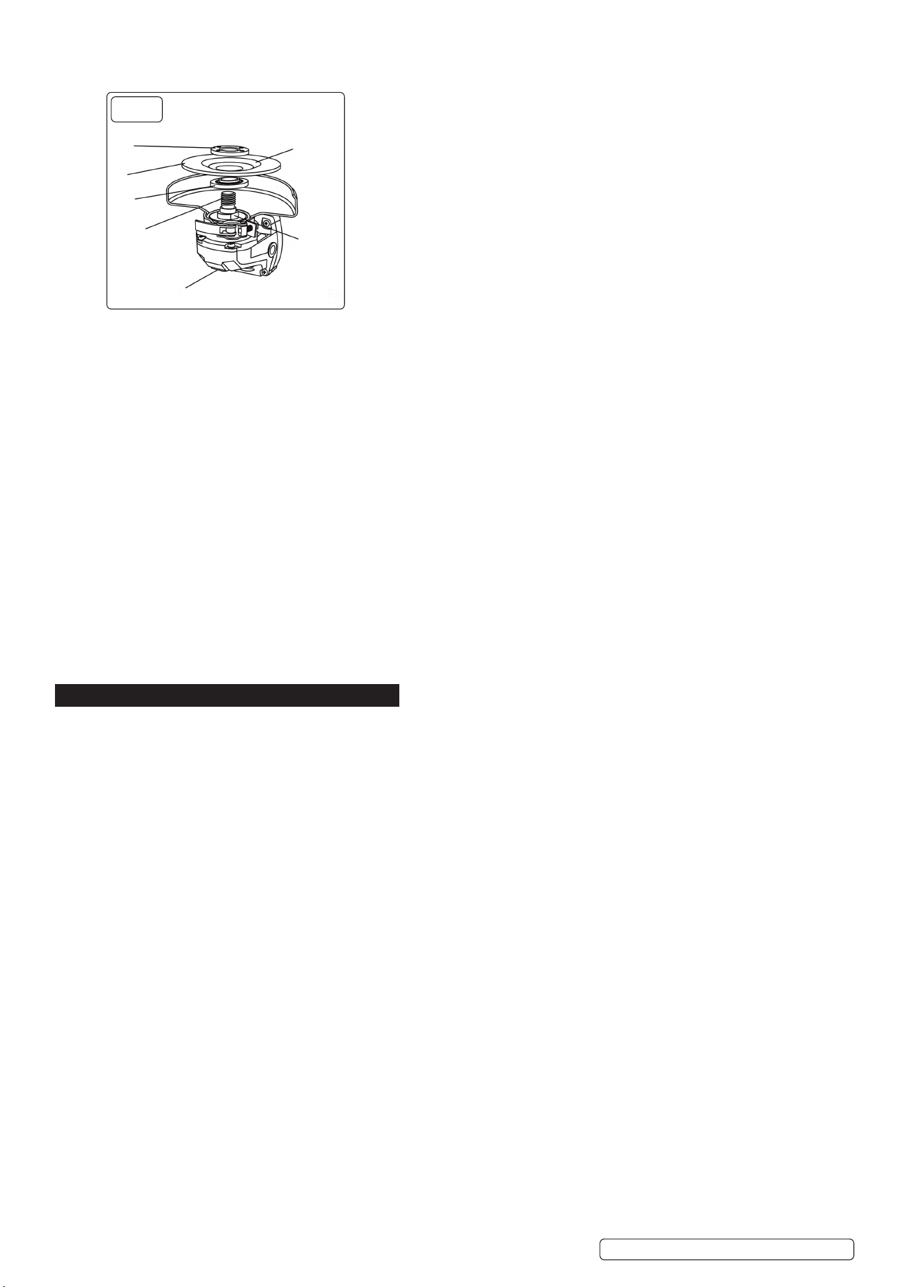
4.5. CHANGING A GRINDING DISC
WARNING! Use the correct size grinding disc. Never use a grinding disc thinner than 5/32” (3.9 mm).
WARNING! Never use a grinding disc with a rated speed of less than (11,000 RPM). A grinding disc with a rated speed of less than
11,000 RPM can break and y apart.
4.5.1. Lock the disc guard onto the spindle housing. Depress the spindle lock button (1) and rotate the grinding disc (2) until the spindle locks
(Fig. 4).
4.5.2. Grasp the grinding disc and rotate the grinding disc in a counterclockwise direction. Once the grinding disc and outer disc ange (3)
are loose, continue to turn the outer disc ange counterclockwise by hand until it is removed from the spindle (4). Remove the grinding
disc from the spindle. NOTE: If the outer ange cannot be loosened by hand, use the wrench provided. DO NOT remove the inner disc
ange (5).
4.5.3. Make sure the ats on the inner disc ange are engaged with the ats on the spindle (6). Place the grinding disc over the spindle with
the concave side of the disc (7) facing outward.
4.5.4. Screw the outer disc ange onto the spindle with the at side of nut facing away from the grinding disc. Tighten to nger tight only.
NOTE: Make sure the raised small diameter portion of both the inner and outer disc anges are tted into the hole in the grinding disc.
4.5.5. Depress the spindle lock button and rotate the grinding disc clockwise until the spindle locks.
4.5.6. Grasp the grinding disc and turn it clockwise to securely tighten the grinding disc and outer ange onto the spindle.
NOTE: You may also tighten the grinding disc and outer ange onto the spindle using the wrench provided.
WARNING! Never attach a wood cutting or carving blade of any type to this angle grinder. It is designed for grinding metal only. Use for
any other purpose is not recommended and creates a hazard which will result in serious injury.
WARNING! Never cover the air vents. They must always be open for proper motor cooling.
5. OPERATION
5.1. SWITCHING ON/OFF
5.1.1. To turn the switch ON, pull the lock-o toggle back and then squeeze the switch lever. To turn the switch OFF, release the switch lever.
5.1.2. To activate the lock-on switch while the angle grinder is running, press the lock-on button. While holding the lock-on button inward,
release the ON/OFF switch. The angle grinder will continue to run.
5.1.3. To turn the angle grinder OFF, squeeze and release the ON/OFF switch.
WARNING! When turning the angle grinder OFF, always wait until the grinding disc comes to a complete stop before setting the tool
down.
5.2. GRINDING
WARNING! Use only wheel types that are specied for your power tool and the specic guard designed for the selected wheel. Wheels
for which the power tool was not designed cannot be adequately guarded and are unsafe.
WARNING! The grinding surface of centre depressed wheels must be mounted below the plane of the guard lip. An improperly
mounted wheel that projects through the plane of the guard lip cannot be adequately protected. The guard must be securely attached
to the power tool and positioned for maximum safety, so the least amount of wheel is exposed towards the operator. The guard helps to
protect the operator from broken wheel fragments, accidental contact with wheel and sparks that could ignite clothing.
WARNING! Wheels must be used only for specied applications. For example: DO NOT grind with the side of cut-o wheel. Abrasive
cut-o wheels are intended for peripheral grinding, side forces applied to these wheels may cause them to shatter.
WARNING! Always use undamaged wheel anges that are of correct size and shape for your selected wheel. Proper wheel anges
support the wheel thus reducing the possibility of wheel breakage. Flanges for cut-o wheels may be dierent from grinding wheel
anges.
8 DO NOT use worn down wheels from larger power tools. A wheel intended for larger power tool is not suitable for the higher speed of a
smaller tool and may burst.
WARNING! When using dual purpose wheels always use the correct guard for the application being performed. Failure to use the
correct guard may not provide the desired level of guarding, which could lead to serious injury.
5.3. Always select and use grinding discs that are recommended for the material to be ground. Make sure that the maximum operating
speed of the grinding disc selected is not less than 11,000 RPM.
5.4. Secure all work before beginning the grinding operation.
WARNING! Never use your angle grinder with the guard removed. It has been designed for use only with the guard installed.
Attempting to use the angle grinder with the guard removed will result in loose particles being thrown against the operator resulting in
serious personal injury.
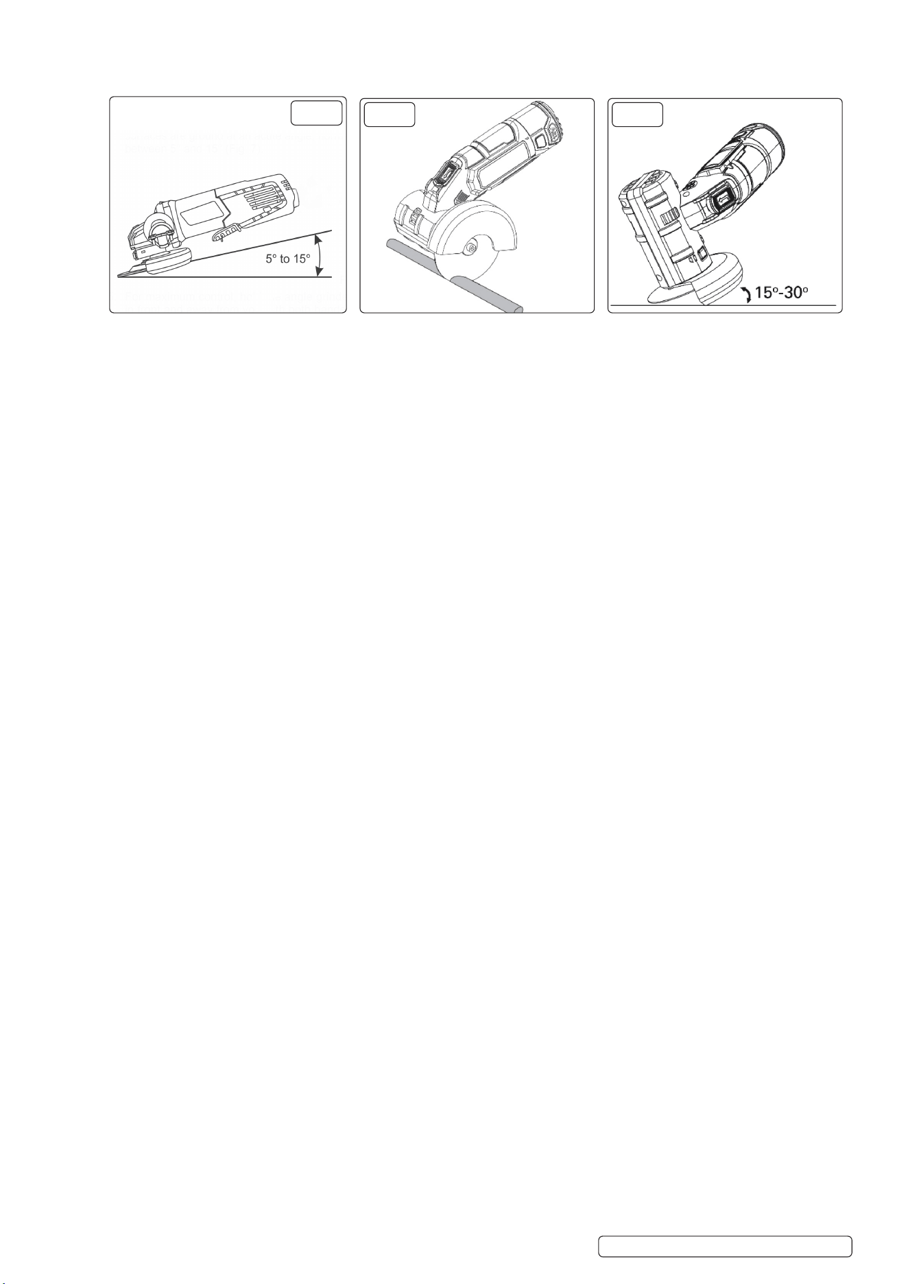
5.4.1. The ecient operation of the angle grinder begins by controlling the pressure and surface contact between the grinding disc and the
workpiece. Flat surfaces are ground at an acute angle, normally between 5° and 15° (Fig.5) on next page.
CP401LI CP401LIHV Issue 1 09/08/24
Original Language Version
© Jack Sealey Limited
FIG.4
1
4
5
2
3
7
6
5.4.2. For maximum control, hold the angle grinder in front and away from you with both hands, keeping the grinding disc clear of the
workpiece.
Start your angle grinder and let the motor and grinding disc build up to full speed. Gradually lower the angle grinder until the grinding
disc contacts the workpiece.
NOTE: For best results keep the angle grinder tilted at an angle of between 5° and 15° degrees and continuously moving at a steady,
consistent pace. Move the angle grinder back and forth or up and down over the work area.
Keep the angle grinder moving so that an excessive amount of material is not removed from one area. If the angle grinder is held in
one spot too long, it will gouge and cut grooves in the workpiece. If the angle grinder is held at too sharp an angle, it will gouge the
workpiece because of the concentration of pressure on a small area.
5.5. CUTTING OFF (FIG.6)
9 Use only wheel types that are recommended for your power tool and the specic guard designed for the selected wheel. Wheels for
which the power tool was not designed cannot be adequately guarded and are unsafe.
WARNING! For cutting metal, always work with the wheel guard for cutting. Workpieces must be adequately secured. When cutting,
work with moderate feed, adapted to the material being cut. DO NOT exert pressure onto the cutting disc, tilt or oscillate the machine.
8 DO NOT reduce the speed of running down cutting discs by applying sidewards pressure.
9 The machine must always work in an up-grinding motion.
9 When cutting proles and square bar, it is best to start at the smallest cross section.
9 The grinding surface of centre depressed wheels must be mounted below the plane of the guard lip. An improperly mounted wheel that
projects through the plane of the guard lip cannot be adequately protected.
5.6. ROUGH GRINDING AND ABRASIVE CUTTING-OFF OPERATIONS (FIG.7)
WARNING! Never use a cutting disc for rough grinding applications. Serious injury to yourself and others can be caused by using the
tool for wrong applications.
WARNING! DO NOT switch the grinder on whilst the disc is in contact with the workpiece. Allow the disc to reach full speed before
starting to grind.
5.6.1. Be prepared for a stream of sparks when the disc touches the metal.
5.6.2. For best tool control, material removal and minimum overloading, maintain an angle between the disc and work surface of
approximately 15°-30° when grinding.
5.6.3. Use caution when working into corners as contact with the intersecting surface may cause the grinder to jump or twist.
5.6.4. When grinding is complete allow the workpiece to cool.
9 Wheels must be used only for recommended applications. For example: DO NOT grind with the side of a cut-o wheel. Abrasive cut-o
wheels are intended for peripheral grinding, side forces applied to these wheels may cause them to shatter.
9 Always use undamaged wheel anges that are of correct size and shape for your selected wheel. Proper wheel anges support the
wheel thus reducing the possibility of wheel breakage. Flanges for cut-o wheels may be dierent from grinding wheel anges.
8 DO NOT use worn down wheels from larger power tools. Wheel intended for larger power tool is not suitable for the higher speed of a
smaller tool and may burst.
8 DO NOT restart the cutting operation in the workpiece. Let the wheel reach full speed and carefully re-enter the cut. The wheel may
bind, walk up or kickback if the power tool is restarted in the workpiece.
5.7. KICKBACK
9 Maintain a rm grip on the power tool and position your body and arm to allow you to resist kickback forces. Always use auxiliary
handle, if provided, for maximum control over kickback or torque reaction during start-up. The operator can control torque reactions or
kickback forces if proper precautions are taken.
9 Use extra caution when making a “pocket cut” into existing walls or other blind areas. The protruding wheel may cut gas or water pipes,
electrical wiring or objects that can cause kickback.
8 NEVER place your hand near the rotating accessory. Accessory may kickback over your hand.
8 DO NOT position your body in the area where power tool will move if kickback occurs. Kickback will propel the tool in direction opposite
to the wheel’s movement at the point of snagging.
9 Use special care when working corners, sharp edges etc. Avoid bouncing and snagging the accessory. Corners, sharp edges or
bouncing have a tendency to snag the rotating accessory and cause loss of control or kickback.
8 DO NOT attach a saw chain woodcarving blade or toothed saw blade. Such blades create frequent kickback and loss of control.
WARNING! When the wheel is binding or when interrupting a cut for any reason, switch o the power tool and hold it motionless until
the wheel comes to a complete stop. Never attempt to remove the cut-o wheel from the cut while the wheel is in motion otherwise
kickback may occur. Investigate and take corrective action to eliminate the cause of wheel binding.
8 DO NOT “jam” the cut-o wheel or apply excessive pressure. DO NOT attempt to make an excessive depth of cut. Over stressing the wheel
increases the loading and susceptibility to twisting or binding of the wheel in the cut and the possibility of kickback or wheel breakage.
8 Support panels or any oversized workpiece to minimize the risk of wheel pinching and kickback. Large workpieces tend to sag under their
own weight. Supports must be placed under the workpiece near the line of cut and near the edge of the workpiece on both sides of the wheel.
CP401LI CP401LIHV Issue 1 09/08/24
Original Language Version
© Jack Sealey Limited
FIG.5
FIG.6
FIG.7
Illustration only
Illustration only Illustration only

5.8. EMISSIONS
8 WARNING! Grinding thin sheets of metal or other easily vibrating structures with a large surface can result in a total noise emission
much higher than the declared noise emission value (Up to 15dB).
6. MAINTENANCE
WARNING! Remove the battery before carrying out any adjustment, servicing or maintenance.
6.1. There are no user serviceable parts in your power tool. Never use water or chemical cleaners to clean your power tool. Wipe clean with
a dry cloth. Always store your power tool in a cool dry place. Keep the motor ventilation slots clean. Keep all working controls free of
dust. Occasionally you may see sparks through the ventilation slots. This is normal and will not damage your power tool.
6.2. CLEANING
6.2.1. The angle grinder MUST be kept clean and dry and must be maintained in accordance with these instructions.
6.2.2. After use, clean o dust and keep in a dry safe place.
6.3. STORAGE
6.3.1. The equipment should ideally be stored in a purpose designed facility where it can be kept secure from unauthorised use.
6.4. TRANSPORT
6.4.1. During transport to the worksite and whilst in store at the work site, the equipment should be protected from exposure to any conditions
which may aect its ability to operate safely. In particular, it should be protected from;
- Exposure to water/sea water.
- Temperatures higher than can be comfortably tolerated by the hand.
- Temperatures below freezing point.
- Solvents.
- Corrosive chemicals.
6.5. DAMAGE
6.5.1. Any angle grinder deemed to be damaged, badly worn, or operates abnormally, MUST BE REMOVED FROM SERVICE! It is
recommended that necessary repairs be made by an authorised service agent.
6.6. SERVICE
9 Have your power tool serviced by a qualied repair person using only identical replacement parts. This will ensure that the safety of the
power tool is maintained.
8 DO NOT service damaged battery packs. Service of battery packs should only be performed by the manufacturer or authorised service
providers.
9 Regularly clean the power tool’s air vents. The motor’s fan will draw the dust inside the housing and excessive accumulation of
powdered metal may cause electrical hazards.
6.7. END OF SERVICE
6.7.1. Through years of normal wear, the angle grinder will eventually become unserviceable. When this happens ensure that it is disposed of
in accordance with local authority regulations.
6.8. BATTERY DISPOSAL
6.8.1. Exposure to high temperatures can cause the batteries to explode; DO NOT dispose of in a re. Some countries have regulations
concerning battery disposal. Follow all applicable regulations. Return used batteries to a collection location for recycling.
7. TROUBLESHOOTING
7.1. If your wheel wobbles or vibrates, check that clamping bolt is tight; check that the wheel is correctly located on the spindle.
7.2. If there is any evidence that the wheel is damaged DO NOT use as the damaged wheel may disintegrate, remove it and replace with a
new wheel. Dispose of old wheels sensibly.
7.3. If working on aluminium or a similar soft alloy, the wheel will soon become clogged and will not grind eectively.
7.4. When used as intended the power tool cannot be subject to overload. When the load is too high or the allowable battery temperature of
75°C is exceeded, the electronic control switches o the power tool until the temperature is in the optimum temperature range again.
7.5. If machine is blocked, please turn o and turn on again after 1~2 seconds.
CP401LI CP401LIHV Issue 1 09/08/24
Original Language Version
© Jack Sealey Limited
WARNING! – RISK OF HAND ARM VIBRATION INJURY.
This tool may cause Hand Arm Vibration Syndrome if its use is not managed adequately.
This tool is subject to the vibration testing section of the Machinery Directive 2006/42/EC.
This tool is to be operated in accordance with these instructions.
This tool has been tested in accordance with: EN IEC 62841-2-3:2020
Declaration and verication of Vibration Emission gures are in accordance with EN IEC 62841-2-3:2020
Measured vibration emission value (a):.................8.13m/s²
Uncertainty value(k):.............................................1.5m/s²
Please note that the application of the tool to a sole specialist task may produce a dierent average vibration emission. We recommend
that a specic evaluation of the vibration emission is conducted prior to commencing with a specialist task.
A health and safety assessment by the user (or employer) will need to be carried out to determine the suitable duration of use for each
tool.
NB: Stated Vibration Emission values are type-test values and are intended to be typical.
Whilst in use, the actual value will vary considerably from and depend on many factors.
Such factors include; the operator, the task and the inserted tool or consumable.
NB: ensure that the length of leader hoses is sucient to allow unrestricted use, as this also helps to reduce vibration.
The state of maintenance of the tool itself is also an important factor, a poorly maintained tool will also increase the risk of Hand Arm
Vibration Syndrome.
Health surveillance.
We recommend a programme of health surveillance to detect early symptoms of vibration injury so that management procedures can
be modied accordingly.
Personal protective equipment.
We are not aware of any personal protective equipment (PPE) that provides protection against vibration injury that may result from the
uncontrolled use of this tool. We recommend a sucient supply of clothing (including gloves) to enable the operator to remain warm
and dry and maintain good blood circulation in ngers etc. Please note that the most eective protection is prevention, please refer to
the Correct Use and Maintenance section in these instructions. Guidance relating to the management of hand arm vibration can be
found on the HSC website www.hse.gov.uk - Hand-Arm Vibration at Work.
CP401LI CP401LIHV Issue 1 09/08/24
Original Language Version
© Jack Sealey Limited
WEEE REGULATIONS
Dispose of this product at the end of its working life in compliance with the EU Directive on Waste Electrical and Electronic Equipment
(WEEE). When the product is no longer required, it must be disposed of in an environmentally protective way. Contact your local solid
waste authority for recycling information.
Sealey Group, Kempson Way, Suffolk Business Park, Bury St Edmunds, Suffolk. IP32 7AR
01284 757500 sales@sealey.co.uk www.sealey.co.uk
ENVIRONMENT PROTECTION
Recycle unwanted materials instead of disposing of them as waste. All tools, accessories and packaging should be
sorted, taken to a recycling centre and disposed of in a manner which is compatible with the environment. When
the product becomes completely unserviceable and requires disposal, drain any uids (if applicable) into approved
containers and dispose of the product and uids according to local regulations.
REGISTER YOUR
PURCHASE HERE
Note: It is our policy to continually improve products and as such we reserve the right to alter data, specications and component parts
without prior notice. Please note that other versions of this product are available. If you require documentation for alternative versions, please
email or call our technical team on technical@sealey.co.uk or 01284 757505.
Important: No Liability is accepted for incorrect use of this product.
Warranty: Guarantee is 12 months from purchase date, proof of which is required for any claim.