INSTRUCTION MANUAL
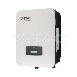
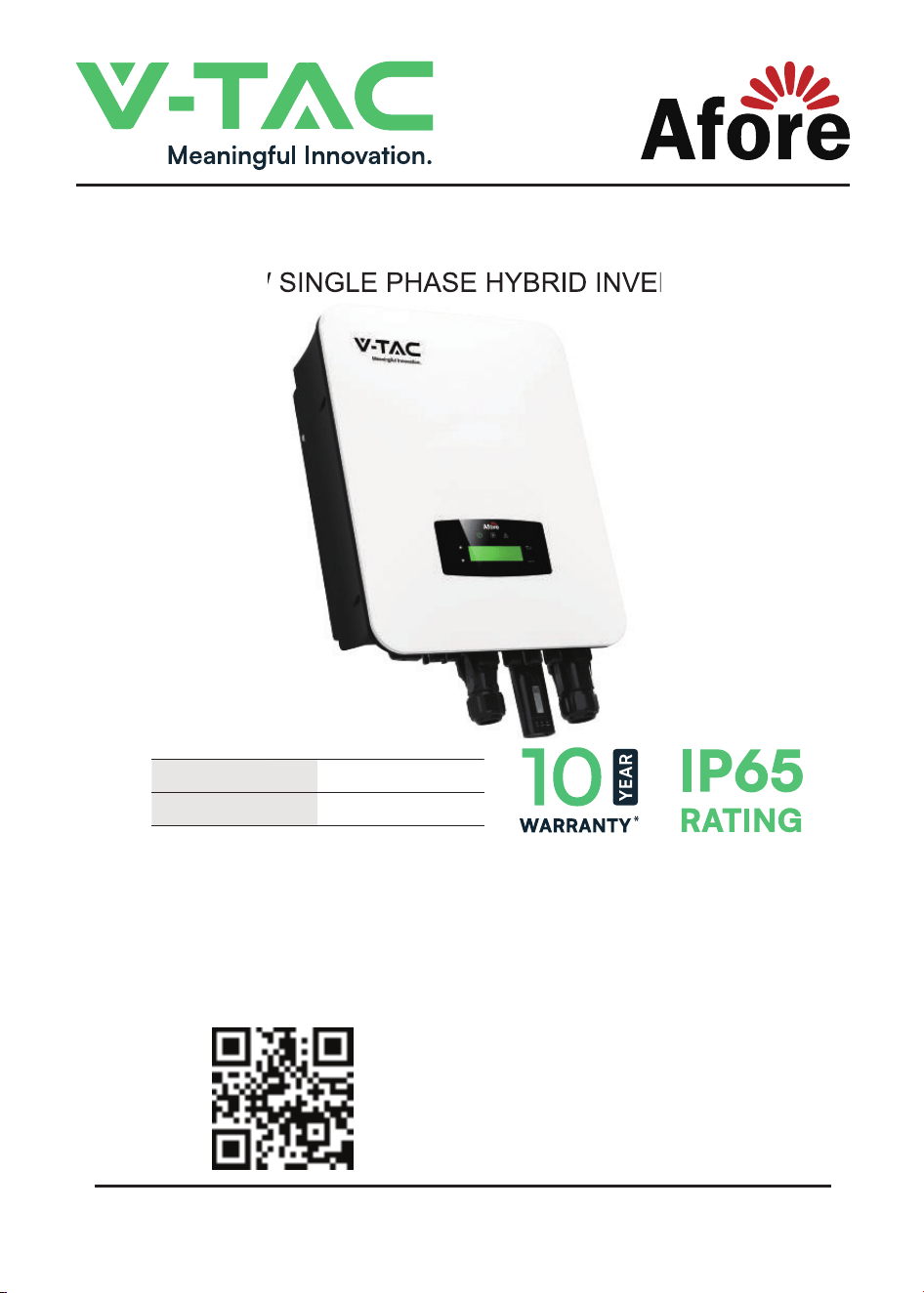
3.6KW SINGLE PHASE HYBRID INVERTER
MODEL VT-6607136
SKU 11955
3.6KW SINGLE PHASE HYBRID INVERTER
INTRODUCTION
IN CASE OF ANY QUERY/ISSUE WITH THE PRODUCT, PLEASE REACH OUT TO US AT: SUPPORT@V-TAC.EU
FOR MORE PRODUCTS RANGE, INQUIRY PLEASE CONTACT OUR DISTRIBUTOR OR NEAREST
DEALERS. V-TAC EUROPE LTD. Karavelow 9B, bul.L, Plovdiv 4000, Bulgaria
Thank you for selecting and buying V-TAC product. V-TAC will serve you the best. Please read these instructions
carefully before starting the installation and keep this manual handy for future reference. If you have any another
query, please contact our dealer or local vendor from whom you have purchased the product. They are trained
and ready to serve you at the best. The warranty is valid for 10 years from the date of purchase. The warranty
does not apply to damage caused by incorrect installation or abnormal wear and tear. The company gives no
warranty against damage to any surface due to incorrect removal and installation of the product. This product is
warranted for manufacturing defects only.
MULTI-LANGUAGE MANUAL QR CODE
Please scan the QR code to access the manual
in multiple languages.
WEEE Number: 80133970

1. About This Manual . . . . . . . . . . . . . . . . . . . . . .
1.1 Scope of Validity . . . . . . . . . . . . . . . . . . . . . . . . . . . . .
1.2 Target Group . . . . . . . . . . . . . . . . . . . . . . . . . . . . . . .
2. Safety & Symbols . . . . . . . . . . . . . . . . . . . . . . .
2.1 Safety Precautions . . . . . . . . . . . . . . . . . . . . . . . . . . . .
2.2 Explanations of Symbols . . . . . . . . . . . . . . . . . . . . . . . . .
3. Introduction. . . . . . . . . . . . . . . . . . . . . . . . . .
3.1 Basic Instruction . . . . . . . . . . . . . . . . . . . . . . . . . . . . . .
3.2 Operation Modes . . . . . . . . . . . . . . . . . . . . . . . . . . . . .
3.2.1 Self-Use . . . . . . . . . . . . . . . . . . . . . . . . . . . . . . . .
3.2.2 Time of Use . . . . . . . . . . . . . . . . . . . . . . . . . . . . . . .
3.2.3 Selling First . . . . . . . . . . . . . . . . . . . . . . . . . . . . . . .
3.2.4 Back-Up . . . . . . . . . . . . . . . . . . . . . . . . . . . . . . . .
4. Installation. . . . . . . . . . . . . . . . . . . . . . . . . . .
4.1 Pre-installation . . . . . . . . . . . . . . . . . . . . . . . . . . . . . . .
4.1.1 Unpacking & Package List . . . . . . . . . . . . . . . . . . . . . . . .
4.1.2 Product Overview . . . . . . . . . . . . . . . . . . . . . . . . . . . .
4.1.3 Mounting Location . . . . . . . . . . . . . . . . . . . . . . . . . . . .
4.2 Mounting . . . . . . . . . . . . . . . . . . . . . . . . . . . . . . . . . .
4.3 Electrical Connection . . . . . . . . . . . . . . . . . . . . . . . . . . .
4.3.1 PV Connection . . . . . . . . . . . . . . . . . . . . . . . . . . . . .
4.3.2 Battery Connection. . . . . . . . . . . . . . . . . . . . . . . . . . . .
4.3.2.1 BAT-CAN/RS485 . . . . . . . . . . . . . . . . . . . . . . . . . . .
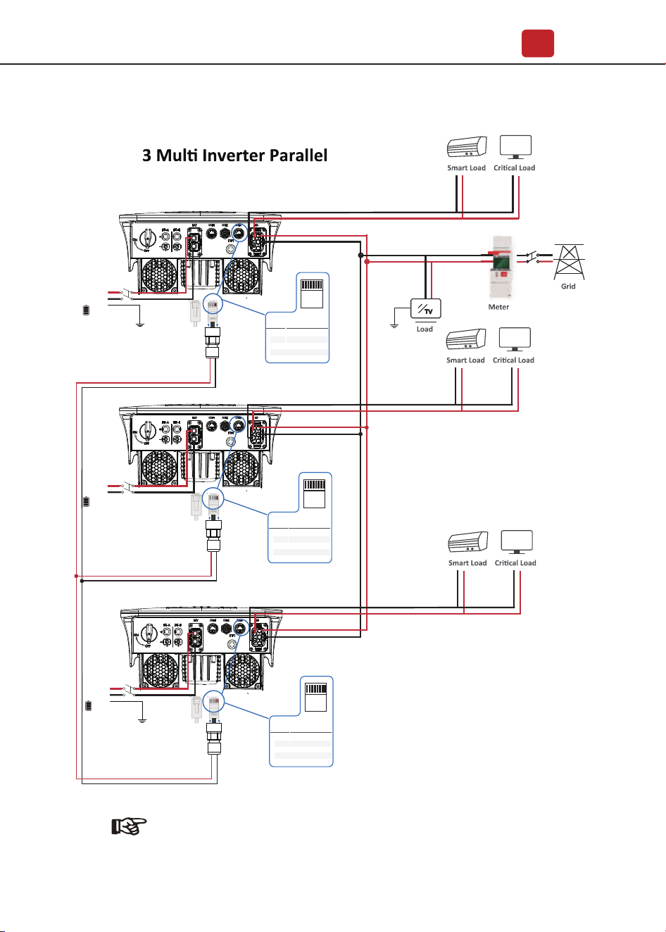
4.3.3 Multi Inverter Parallel . . . . . . . . . . . . . . . . . . . . . . . . .
12123 4.3.4 AC Connection . . . . . . . . . . . . . . . . . . . . . . . . . . . . .
4.3.5 CT or Meter Connection . . . . . . . . . . . . . . . . . . . . . . . . .
4.4 Communication Connection. . . . . . . . . . . . . . . . . . . . . . . .
4.5 Earth Connection. . . . . . . . . . . . . . . . . . . . . . . . . . . . . .
Contents
Contents
1
1
1
1
1
2
3
3
3
3
4
6
6
7
7
7
8
9
11
12
13
14
17
18
19
21
23
24

5. Operation . . . . . . . . . . . . . . . . . . . . . . . . . . .
5.1 Control Panel . . . . . . . . . . . . . . . . . . . . . . . . . . . . . . .
5.2 Menu Overview . . . . . . . . . . . . . . . . . . . . . . . . . . . . . .
5.3 Control Panel . . . . . . . . . . . . . . . . . . . . . . . . . . . . . . .
5.3.1 Time & Date . . . . . . . . . . . . . . . . . . . . . . . . . . . . . .
5.3.2 Safety . . . . . . . . . . . . . . . . . . . . . . . . . . . . . . . . .
5.3.3 Lithium Battery . . . . . . . . . . . . . . . . . . . . . . . . . . . . .
5.3.4 PV Mode . . . . . . . . . . . . . . . . . . . . . . . . . . . . . . . .
5.3.5 Lead Acid . . . . . . . . . . . . . . . . . . . . . . . . . . . . . . . .
5.3.6 Energy Management System (EMS Param) . . . . . . . . . . . . . . . .
5.3.7 Timing of Use . . . . . . . . . . . . . . . . . . . . . . . . . . . . . .
5.3.8 AC Charging . . . . . . . . . . . . . . . . . . . . . . . . . . . . . .
5.3.9 Forced Charging . . . . . . . . . . . . . . . . . . . . . . . . . . . .
5.3.10 Forced Discharging. . . . . . . . . . . . . . . . . . . . . . . . . . .
5.3.11 Protection Parameters . . . . . . . . . . . . . . . . . . . . . . . . .
5.3.12 Power grid control . . . . . . . . . . . . . . . . . . . . . . . . . .
5.3.13 Multi-machine in Parallel . . . . . . . . . . . . . . . . . . . . . . . .
5.3.14 Diesel Generator Setting (Diese1 Gen Param) . . . . . . . . . . . . . .
6. Power ON/OFF . . . . . . . . . . . . . . . . . . . . . . . .
6.1 Power ON . . . . . . . . . . . . . . . . . . . . . . . . . . . . . . . . .
6.2 Power OFF . . . . . . . . . . . . . . . . . . . . . . . . . . . . . . . .
6.3 Restart . . . . . . . . . . . . . . . . . . . . . . . . . . . . . . . . . . .
7. Maintenance & Trouble Shooting . . . . . . . . . . . . . .
7.1 Maintenance . . . . . . . . . . . . . . . . . . . . . . . . . . . . . . .
7.2 Trouble Shooting . . . . . . . . . . . . . . . . . . . . . . . . . . . . .
8. Specifications . . . . . . . . . . . . . . . . . . . . . . . .
Contents
25
25
26
26
27
27
28
28
29
29
30
31
31
32
33
33
34
35
35
36
36
36
36
36
36
47
1.About This Manual 1.About This Manual
1. Please make sure to turn off the power before starting the installation.1. Please make sure to turn off the power before starting the installation.
2. Installation must be performed by a qualified electrician.2. Installation must be performed by a qualified electrician.
2.Safety & Symbols 2.Safety & Symbols
2.1 Safety Precautions2.1 Safety Precautions
WARNINGWARNING
1. All work on the inverter must be carried out by qualified electricians.1. All work on the inverter must be carried out by qualified electricians.
2. The device may only be operated with PV panels.2. The device may only be operated with PV panels.
3. The PV panels and inverter must be connected to the ground.3. The PV panels and inverter must be connected to the ground.
4. Do not touch the inverter cover until 5 minutes after disconnecting both DC and 4. Do not touch the inverter cover until 5 minutes after disconnecting both DC and
AC power supply.AC power supply.
5.Do not touch the inverter enclosure when operating, keep away from materials 5.Do not touch the inverter enclosure when operating, keep away from materials
that may be affected by high temperatures.that may be affected by high temperatures.
6. Please ensure that the used device and any relevant accessories are disposed of 6. Please ensure that the used device and any relevant accessories are disposed of
in accordance with applicable regulations.in accordance with applicable regulations.
7. VTAC invertershould be placed upwards and handled with care in delivery. Pay 7. VTAC invertershould be placed upwards and handled with care in delivery. Pay
attention to waterproof. Do not expose the inverter directly to water, rain, snow or attention to waterproof. Do not expose the inverter directly to water, rain, snow or
spray.spray.
8. Alternative uses, modifications to the inverter not recommended. The warranty 8. Alternative uses, modifications to the inverter not recommended. The warranty
can become void if the inverter was tampered with or if the installation is not in can become void if the inverter was tampered with or if the installation is not in
accordance with the relevant installation instructions.accordance with the relevant installation instructions.
About This Manual About This Manual
0101
Safety & Symbols
02
VTAC inverterstrictly comply with relevantsafety standards. Please read and
follow all the instructions and cautions during installation, operation and
maintenance.
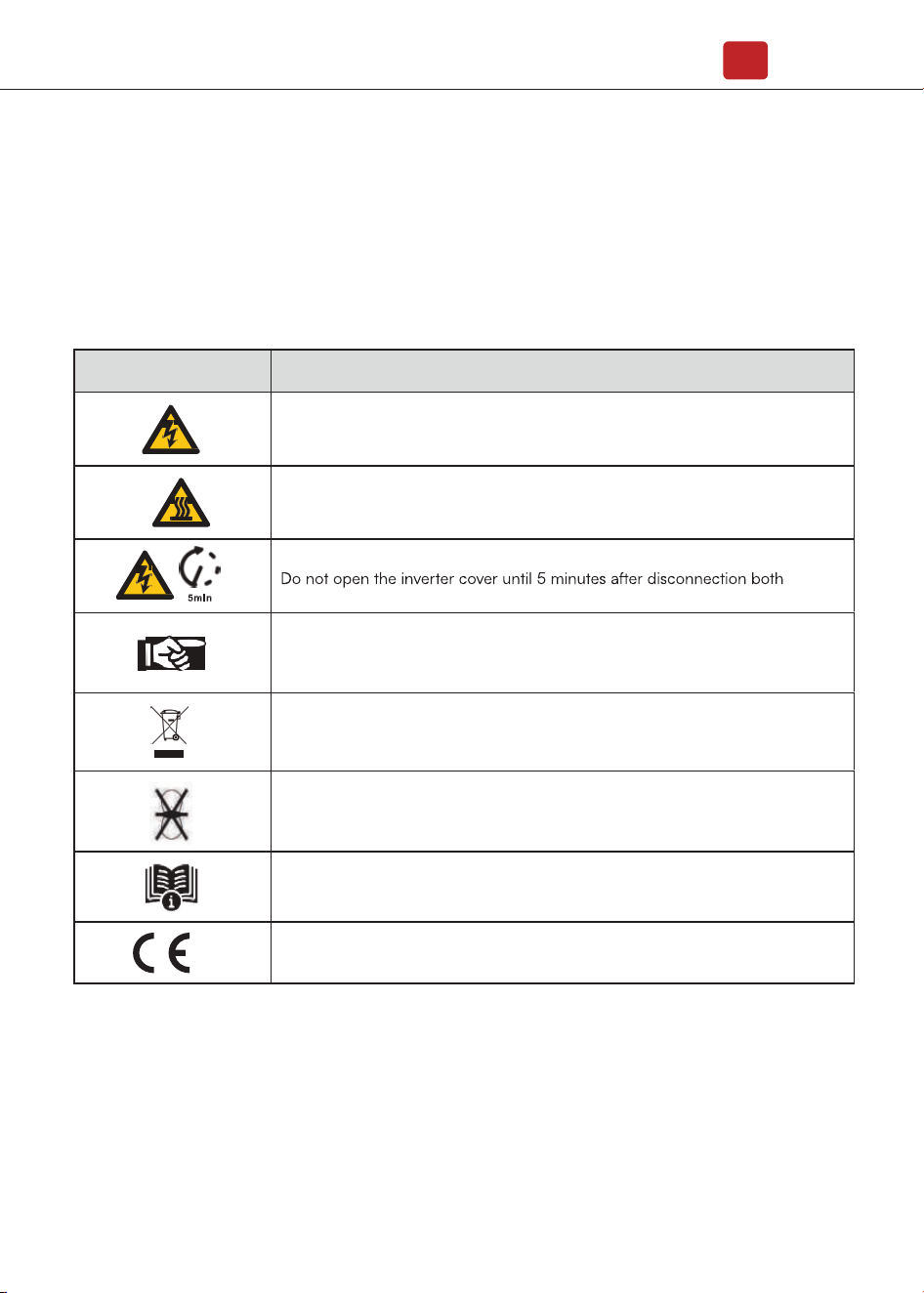
2.2 EXPLANATION OF SYMBOL
SYMBOL EXPLANATION
Danger of electric shock
The inverter contains fatal DC and AC power. All work on the inverter must be
carried out by qualified personnel only.
Beware of hot surface
The inverter’s housing may reach uncomfortably hot 60°C (140°F) under high
power operation. Do not touch the inverter enclosure when operation.
Residual power discharge
DC and AC power supply.
Important notes
Read all instructions carefully. Failure to follow these instructions,
warnings and precautions may lead to device malfunction or damage.
Do not dispose of this device with the normal domestic waste.
Without transformer
This inverter does not use transformer for the isolation function.
Refer to manual before service.
CE mark
The inverter complies with the requirements of the applicable CE guidelines.
3. Introduction
3.1 Basic Instruction
The VTAC hybrid inverters are designed to increase energy independence for
homeowners. Energy management is based on time-of-use and demand charge
rate structures, significantly reduce the amount of energy purchased from the
public grid and optimize self-consumption.
Introduction
03
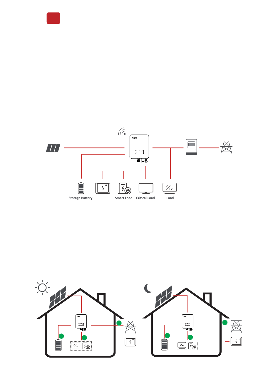
3.2 Operation Modes
PV Array
Grid
Meter
Hybrid Inverter
Generator
TV
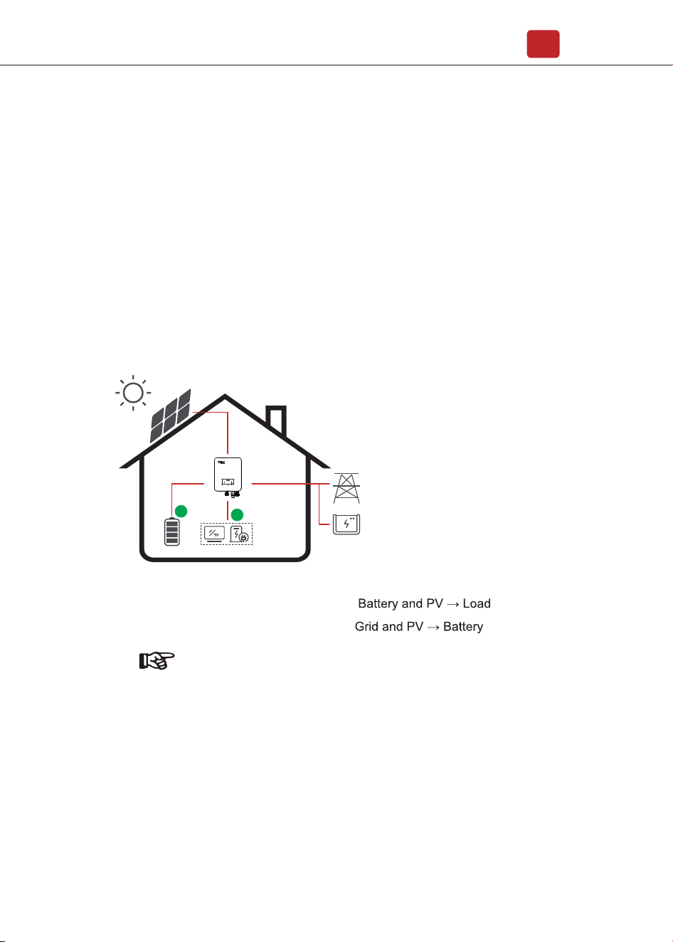
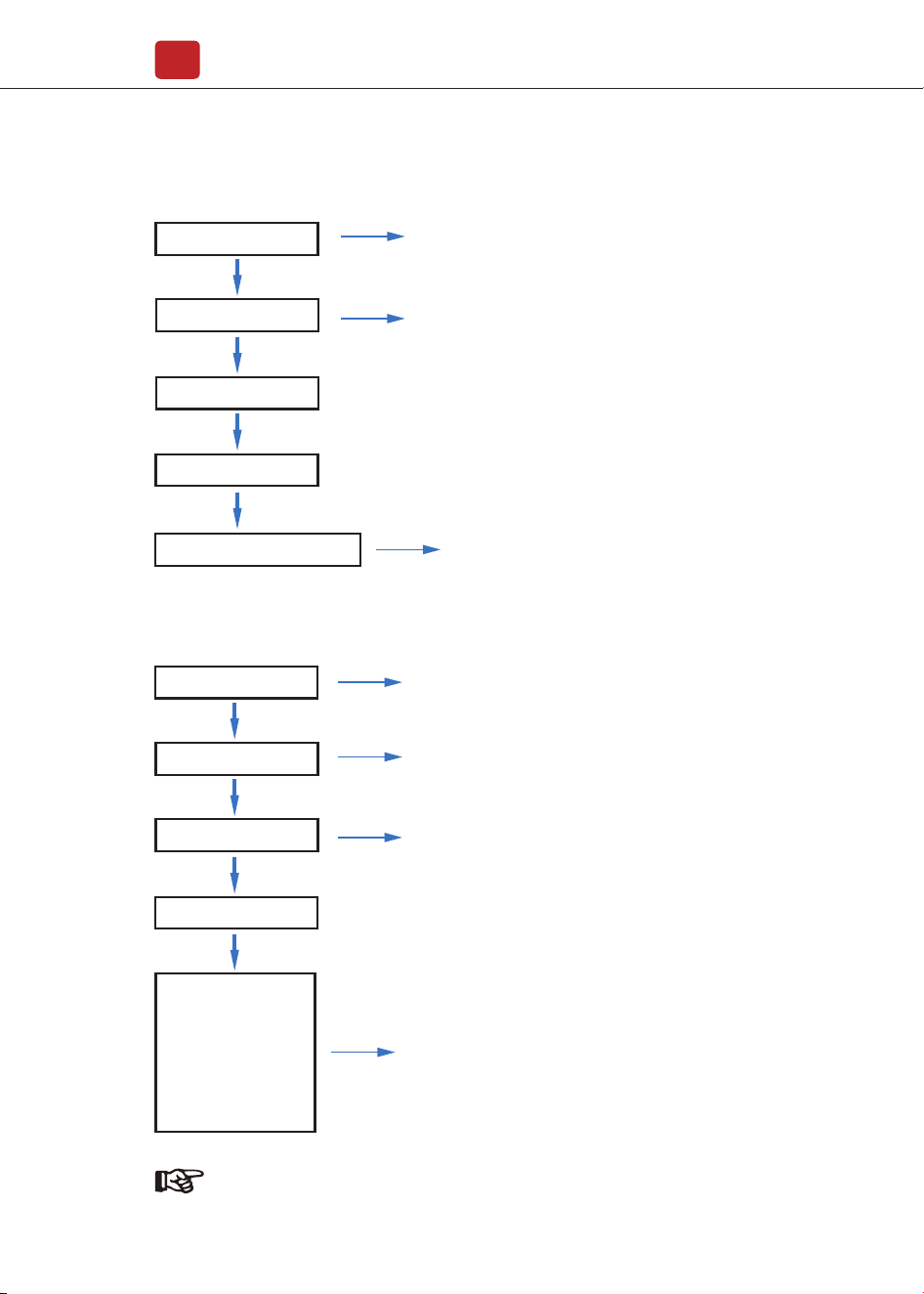
3.2.1 SelfUse
The SelfUse mode is for the regions with low feed-in tariff and high electricity
prices. The energy produced by the PV system is used to optimize
self-consumption needs. The excess energy is used to recharge the batteries,
any remaining excess is then exported to the grid.
TV
1
2
3
TV
1
2
3
Introduction
04
When select 0 W under P_Feed menu, the inverter will export zero energy to the
grid.
When select xx W under P_Feed menu, the inverter will export customized
energy to the grid.
Note: Advance Setting
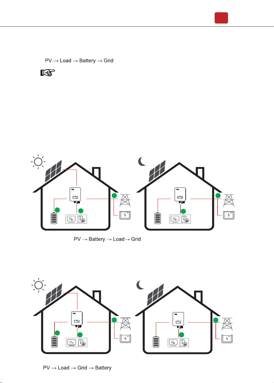
Energy flow:
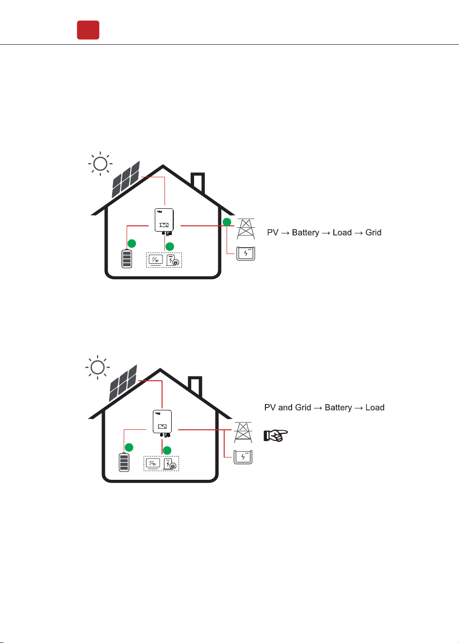
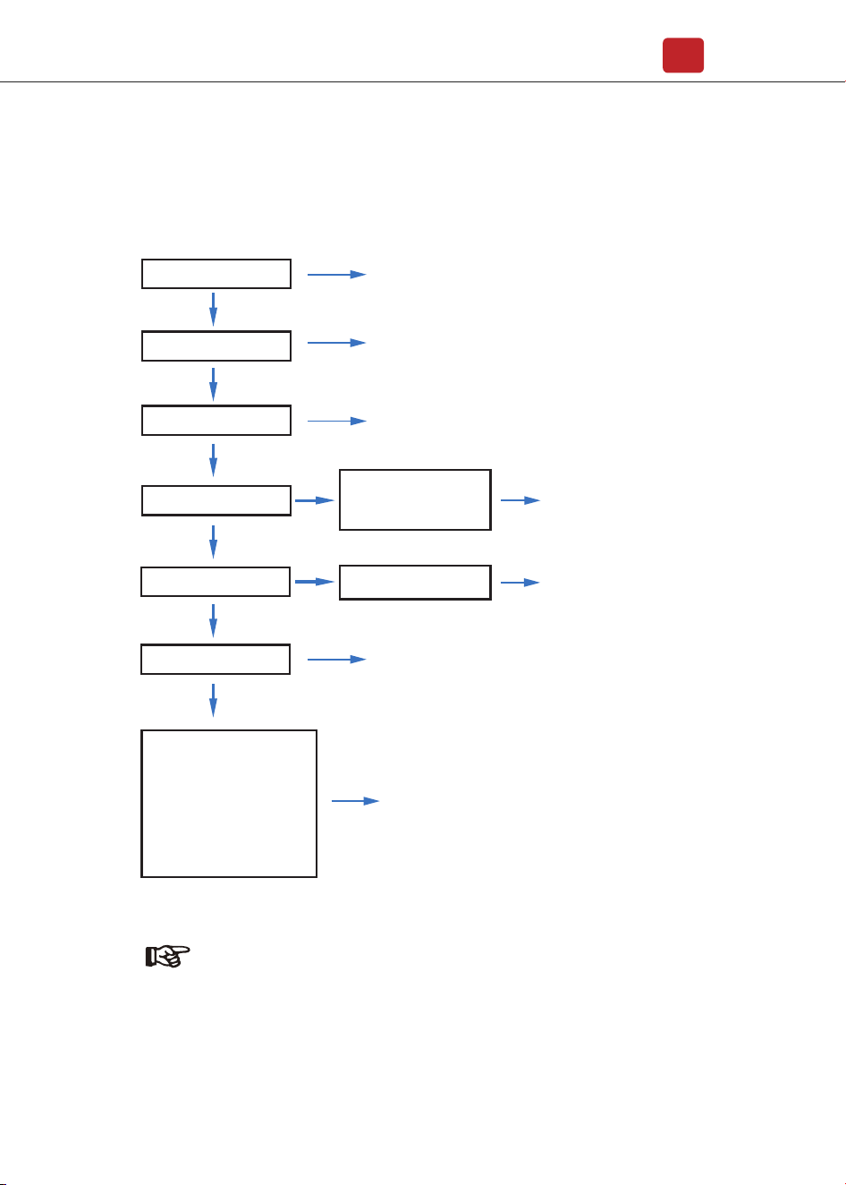
3.2.2 ChgFst
3.2.3 SellFst
The SellFst mode is suitable for the regions with high feed-in tariff.
TV
Energy flow:
1
3
2
TV
1
2
Energy flow:
TV
1
2
3
TV
1
2
When the grid fails, the system will automatically switch to ChgFst mode. The
back-up loads can be supplied by both PV and battery energy.
Introduction
03
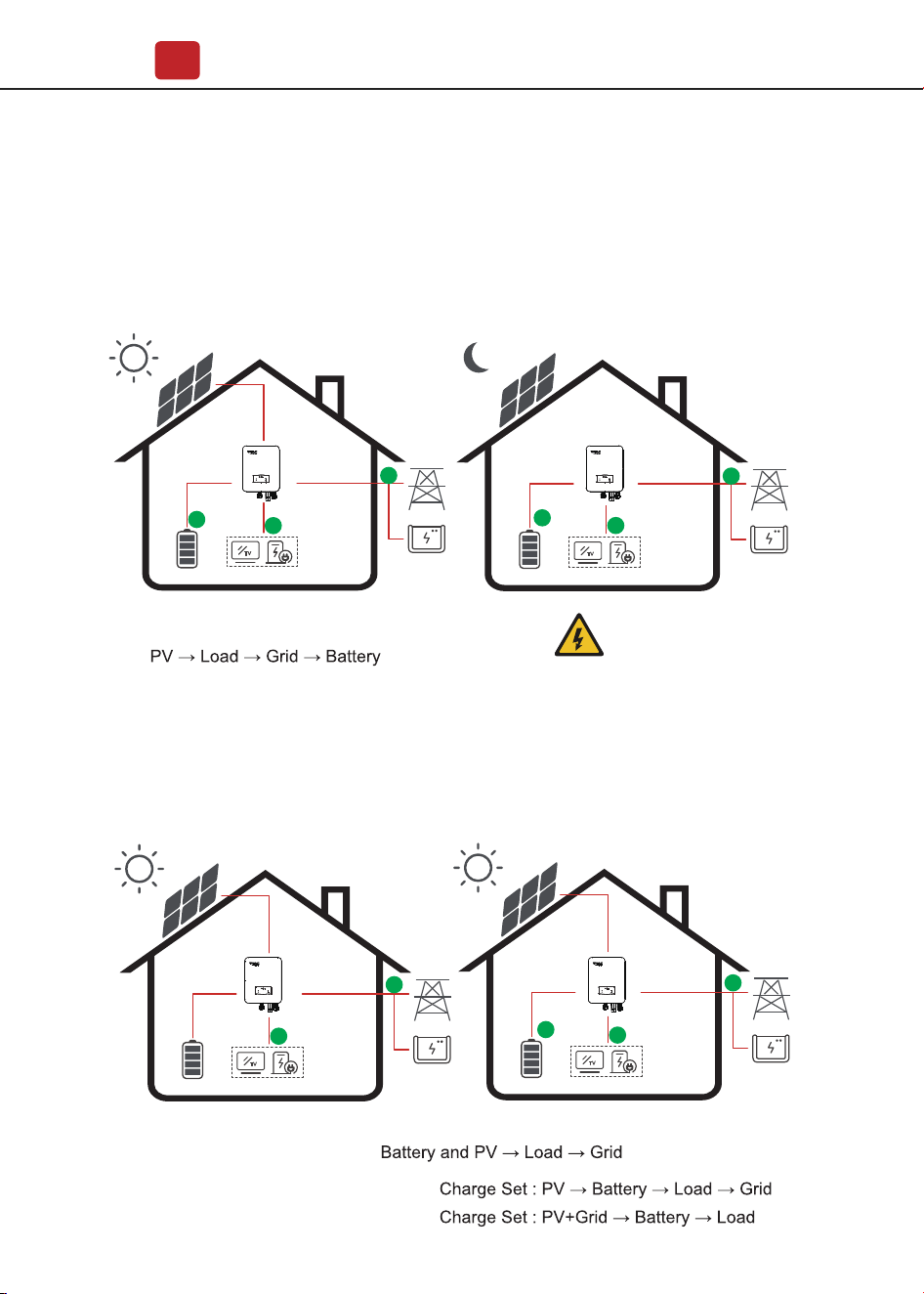
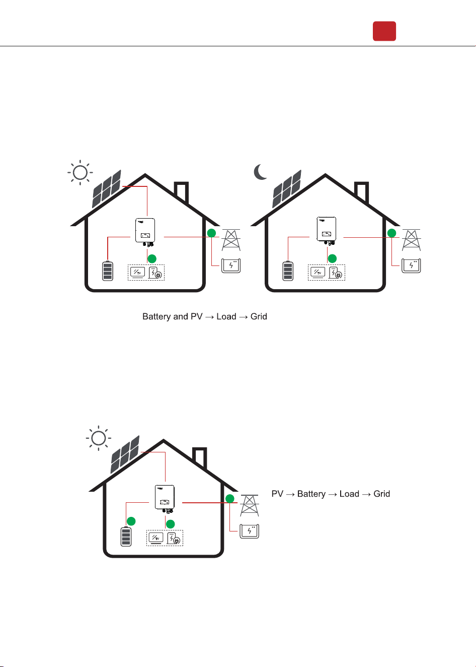
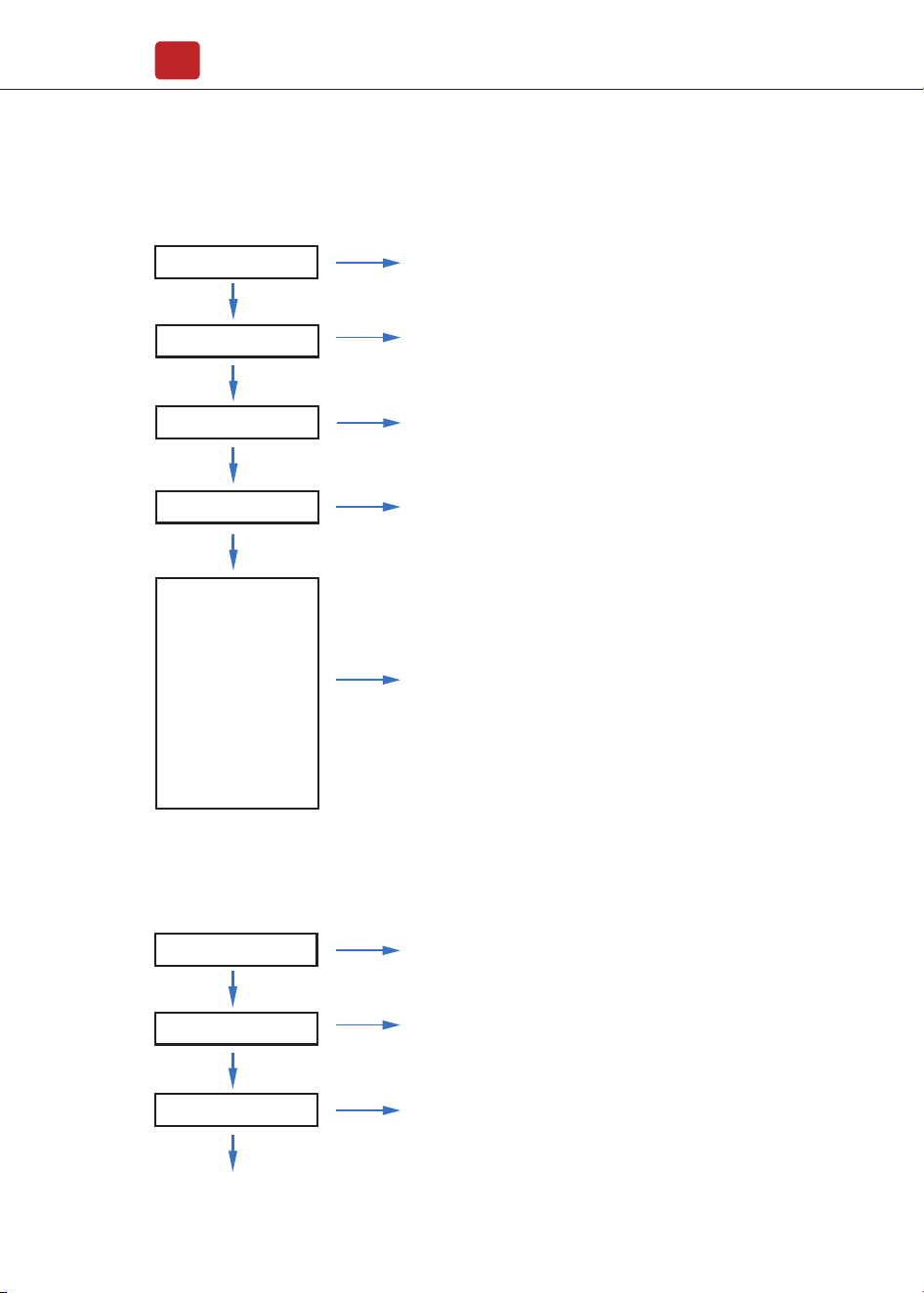
3.2.4 Maintain
3.2.5 cmdChg
The Maintain mode is suitable for situations where the battery capacity is small,
and the battery is charged and discharged at the specified power.
In cmdChg mode, within the battery power range, the battery is charged and
discharged at the specified power.
TV
Energy flow:
1
3
3
2
TV
1
2
Discharge:
Charge:
P
PV > P
PPV < P
Discharge
Charge
Energy flow:
TV
1
2
TV
2
3
1
Warning:
The Maintain mode is only
available for some inverter.
Introduction
04
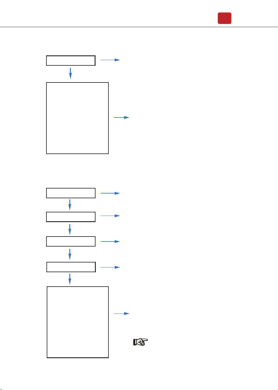
3.2.6 ExtEms
3.2.8 Time of Use
ExtEms mode requires customized external control accessories that can remotely
control the operation of the inverter. It is not recommended to use it without
professional personnel.
3.2.7 PeakShave
In PeakShave mode, the charging and discharging of the battery are controlled by
setting the AC power to reduce the peak load of the power grid.
The Time of Use mode is designed to reward customers who do their part to
reduce demand on the electric grid, particularly during peak usage periods. Use
most of your electricity from PV energy and during off-peak time periods, and you
could significantly lower your monthly bill.
Grid power > P_Back :
Energy flow:
Grid power < P_Back:
TV
1
1
2
Note:
P_ Back is set to Grid Ctr1 in the Run Param directory of the menu.
Introduction
05
A. Charge Setting
PV Charge Mode
4 periods of time charge setting.
4 periods of time charge setting.
TV
Energy flow:
2
1
TV
Energy flow:
2
1
3
AC Charging
Note:
After select AC charge,
the AC will also charge the
battery when the PV is low
or no PV.
Introduction
06
B. Forced Discharging
4 periods of time discharge setting
Energy flow:
TV
1
2
TV
1
2
C. Forbidden Discharge
4 periods of time discharge setting, the battery will be charged firstly.
TV
Energy flow:
2
1
3
Installation
07
4. Installation
4.1 Pre-installation
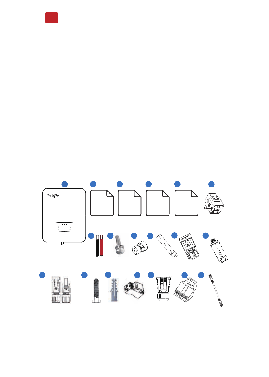
4.1.1 Unpacking & Package List
Unpacking
On receiving the inverter, please check to make sure the packing and all
components are not missing or damaged. Please contact your dealer directly for
supports if there is any damage or missing components.
Package List
Open the package, please check the packing list shown as below.
3
7
6
9
10
5
Monitoring
Quick
Installation
Instructions
54
1
Quick
Installation
Instructions
Warranty
Card
2
12
514
13
11
Certificate
Of Inspection
17
18
19
515
16
8
Introduction
08
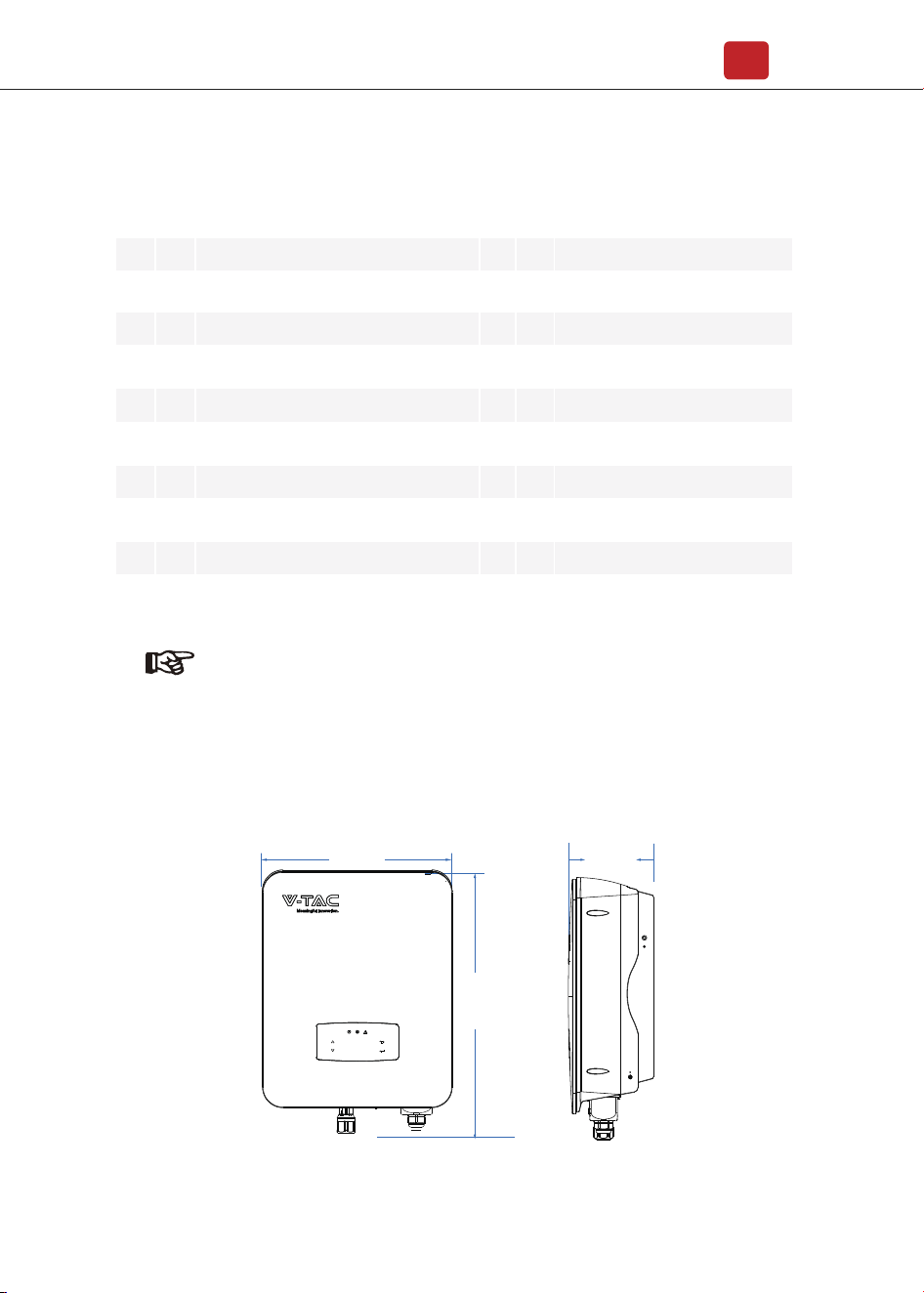
4.1.2 Product Overview
370mm
535mm
192mm
No.
Qty Items No. Qty Items
1
1
1
1
1
1
1
1
3
1
Hybrid Inverter
Certificate Of Inspection
Quick Installation Instructions
Warranty Card
Monitoring Quick Installation Instructions
Monitor Module
Battery wire
Security Screw
1
1
2
3
3
1
1
1
2
1
2
3
4
5
6
7
8
9
10
11
12
13
14
15
16
17
18
19
CT
Communication Connectors
DC Connector
Battery Connector
Mounting Bracket Screw
Plastic Expansion Tube
Smart Meter (Opitional)
AC Waterproof Cover
Communication Adapter
Communication T568B
Wall Mounting Bracket
Note:
Using the Communication Adapter when Multi Inverter Parallel.
Installation
09
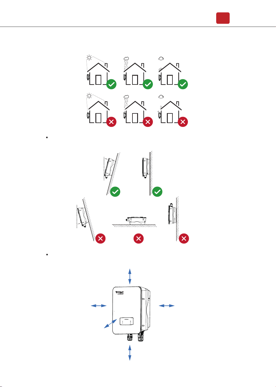
The inverters are designed for indoor and outdoor installation (IP65), to increase
the safety, performance and lifespan of the inverter, please select the mounting
location carefully based on the following rules:
• The inverter should be installed on a solid surface, far from flammable or
corrosion materials, where is suitable for inverter’s weight and dimensions.
• The ambient temperature should be within -25℃ ~ 60℃ (between -13 °F and
140°F).
• The installation of inverter should be protected under shelter. Do not expose
the inverter to direct sunlight, water, rain, snow, spray lightning, etc.
4.1.3 Mounting Location
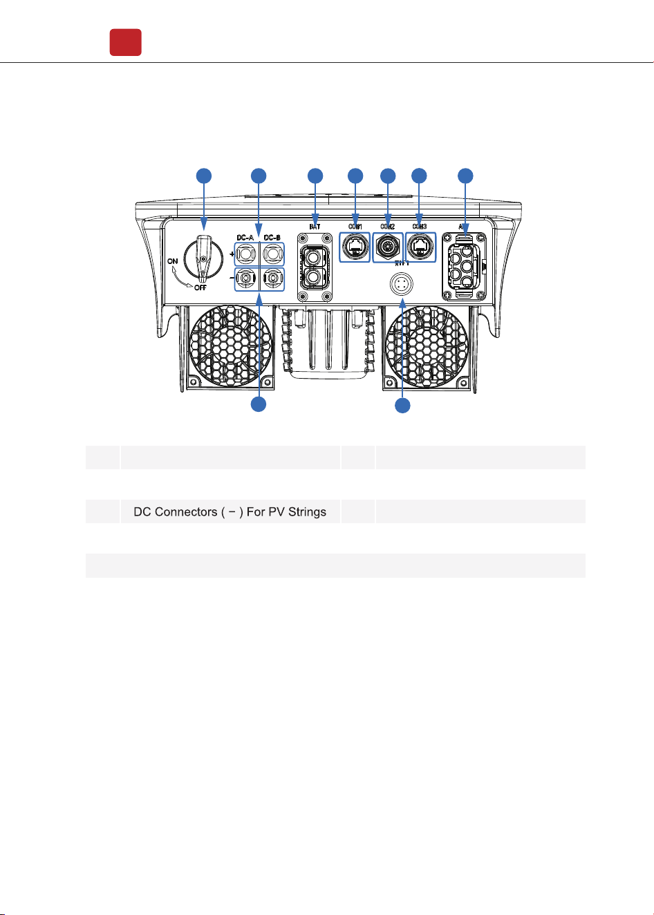
Inverter Terminals
2
No. Items
DC Switch
DC Connectors ( + ) For PV Strings
Battery Port
Generator Communication Port
1
2
3
4
5
No. Items
CT/Meter Communication Port
BAT Communication Port
AC Port & EPS Port
Monitor Module Port
6
7
8
9
1 4 5
6
7
8
3
9
Installation
10
The inverter should be installed vertically on the wall, or lean back on plane
with a limited tilted angle.
Leave the enough space around inverter, easy for accessing to the inverter,
connection points and maintenance.
<15°
>0°
Max
300mm
300mm 300mm
500mm
50mm
Installation
11
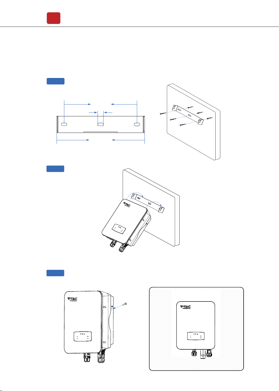
4.2 Mounting
Step 1
Step 3
Step 2
264mm
219mm
17mm
Security
screw
Installation
12
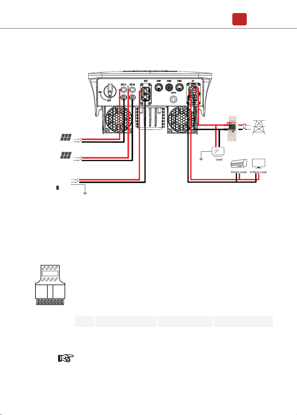
4.3 Electrical Connection
Note:
For diesel generators or multi-machine parallel use, please contact the
manufacturer, and provide installation and operation instructions
separately.
Communication Adapter pin assignment
Grid
Smart meter
TV
12345678
No.
COM2
1
2
3
4
5
6
7
8
COM3
SGND
TEP
485-A2
CANH_BAT1
CANL_BAT1
485-B2
CT-U
RS485-A
CT-N
BAT-485-A
BAT-485-B
RS485-B
COM1
SELV12
RPSD
+3_3V
DRM1/5
DRM2/6
DRM3/7
DRM4/8
DRM0
PV Array
PV Array
Installation
13
• The open-circuit voltage and short-circuit current of PV string should not exceed
the reasonable range of the inverters.
• The polarity of PV strings are correct.
• Use the DC plugs in the accessory.
• The lightning protector should be equipped between PV string and inverter.
• Disconnect all of the PV (DC) switch during wiring.
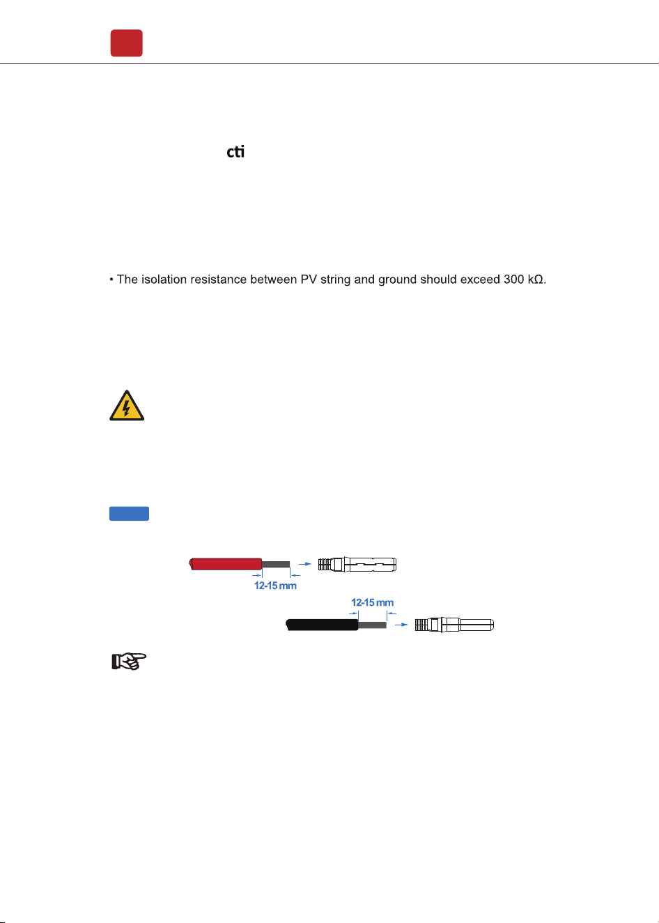
4.3.1 PV Conne on
The hybrid inverter has one/two MPPT channels, can be connected
with one/two strings of PV panels. Please make sure below requirements are
followed before connecting PV panels and strings to the inverter:
Step 1
Note:
PV cable suggestion
Cross-section
4mm²
Warning:
The fatal high voltage may on the DC side, please comply with
electric safety when connecting.
Please make sure the correct polarity of the cable connected with
inverter, otherwise inverter could be damaged.
Installation
14
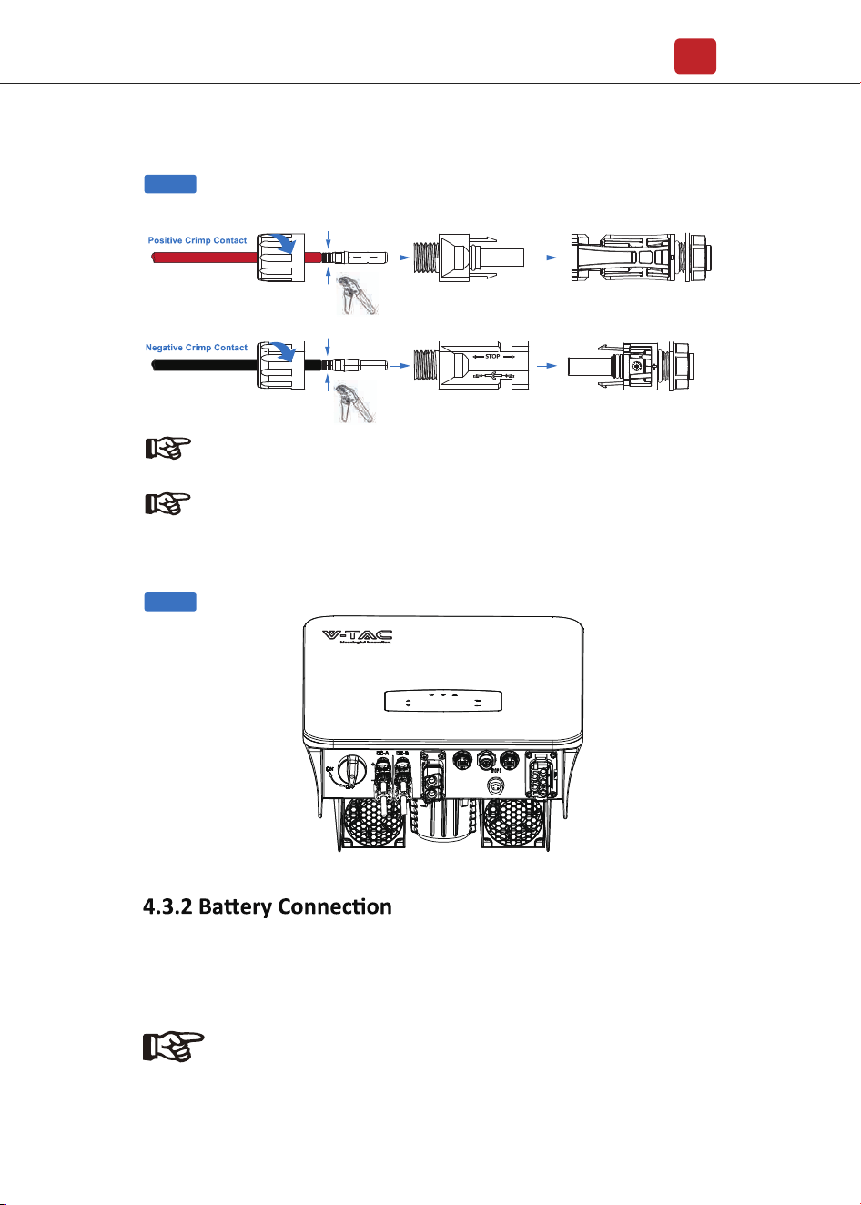
Note:
Please use PV connector crimper to pinch the point of the arrow.
Step 2
Step 3
Note:
You’ll hear click sound when the connector assembly is correct.
Hybrid inverters are compatible with lithium battery. For lead acid
battery or batteries with other brands, please confirm with local distributor or
VTAC for technical support.
Note:
Set battery type and manufacturer, please refer to Chapter 5.3.
BMS(Battery Management System)communication is needed
between inverter and battery.
MC
MC
�
Installation
15
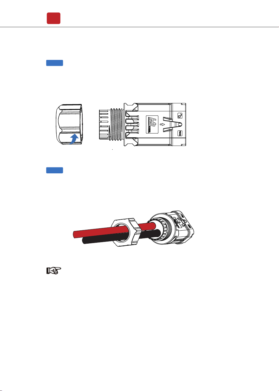
Note:
Battery cable suggestion Cross - section 4 AWG
Please make sure the battery polarities are correct.
Step 1
Rotate counterclockwise and remove mounting bracket screw nut.
Pass the battery wire with the correct polarity through the nut and
installation bracket.
Step 2
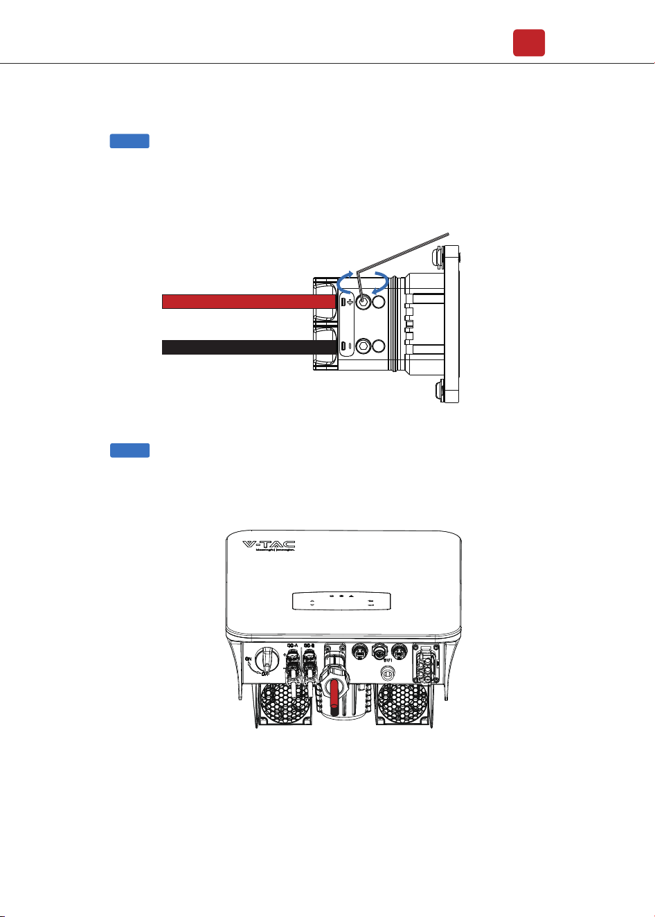
Installation
16
Insert the battery wire into the corresponding terminal and lock it with
a hexagon wrench.
Step 3
Insert the battery connector into the inverter, if hear a “click”, it means the battery
connection is finished.
Step 4
Installation
17
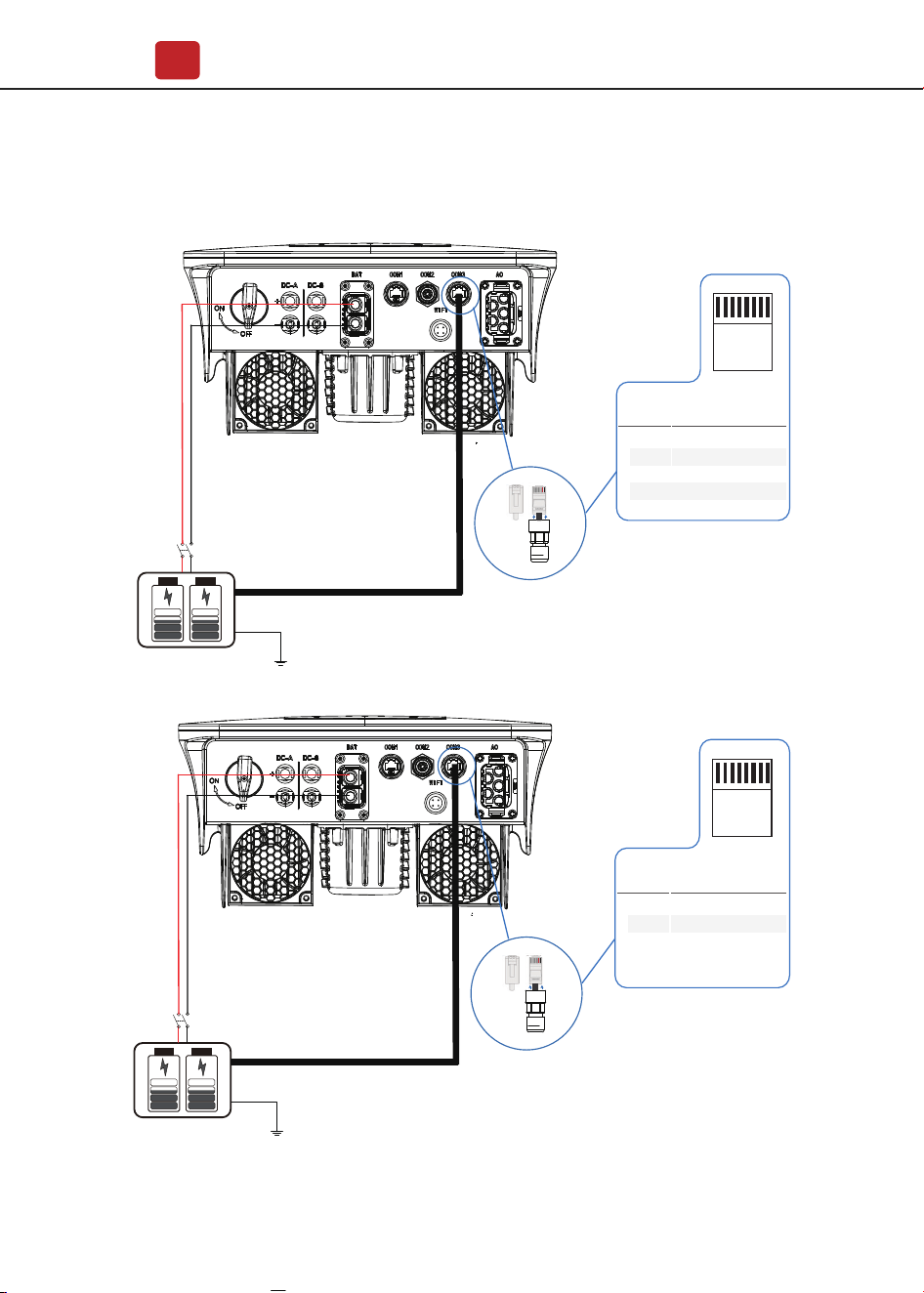
4.3.2.1 BAT-CAN/RS485
CAN/RS485
Lithium
CAN-485
4
1-3
5
6-8
PIN
Assignment
CANH_BAT1
/
T568B
12345678
CANL_BAT1
/
Pin123454678
Pin87654321
CAN/RS485
Lithium
Pin123454678Pin87654321
BAT-485
7
1-6
8
PIN
Assignment
BAT-485-A
/
T568B
12345678
BAT-485-B
Installation
18
Note:
The meter only communicates with the host and does not
communicate with the machine. Refer to chapters 4.3.5.
4.3.
3
1-2
4-5
6
7-8
PIN
Assignment
485-A2
/
RJ45 Plug
1234567 8
/
/
485-B2
3
1-2
4-5
6
7-8
PIN
Assignment
485-A2
/
RJ45 Plug
1234567 8
/
/
485-B2
3
1-2
4-5
6
7-8
PIN
Assignment
485-A2
/
RJ45 Plug
1234567 8
/
/
485-B2
485A 485B
Installation
19
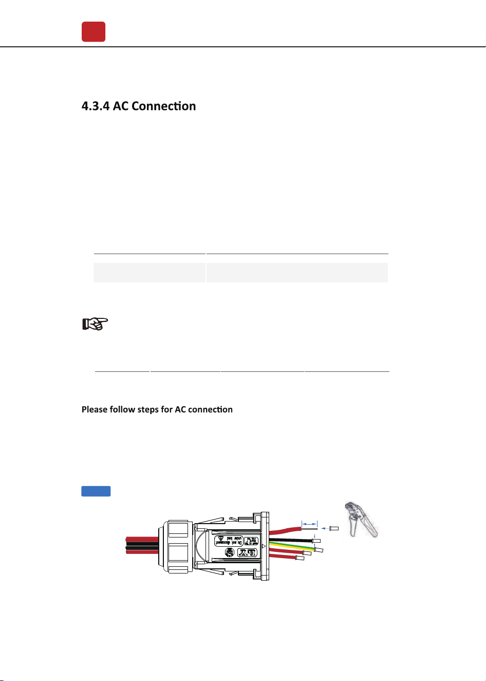
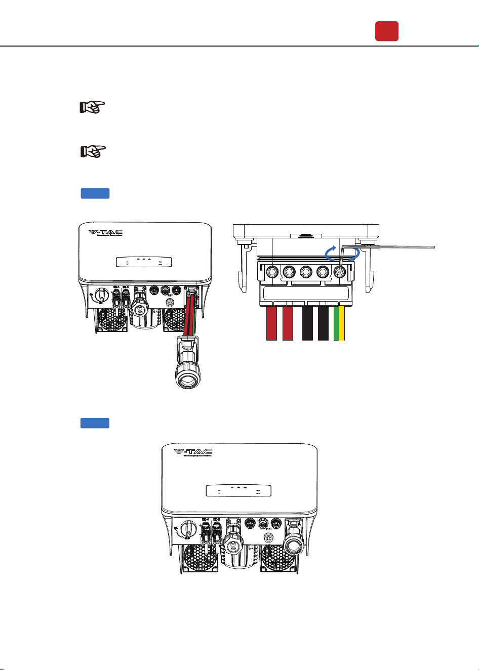
Before connecting, a separate AC breaker between individual inverter and AC
input power is necessary. This will ensure the inverter be securely disconnected
during maintenance and fully protected from current of AC input.
An extra AC breaker is needed for On-Grid connection to be isolated from grid
when necessary. Below are requirements for the On-Grid AC-breaker.
•
Connect breaker first before connecting.
•
emove insulation sleeve 11mm(0.5 inch) length, unscrew the bolts, insert the
AC input wires according to polarities indicated on the terminal block and
tighten the terminal screws.
Note:
Qualified electrician will be required for the wiring.
The AC terminal contains “GRID” and “EPS”, GRID for load, and EPS for
emergency load.
Inverter Model AC breaker specification
VT-6607136
63A/200V/230V AC breaker
Cable(mm²)
4-6 1.2N·m
Torque value
Model
VT-6607136 8-10AWG
Wire Size
Step 1
10±0.5mm
Installation
20
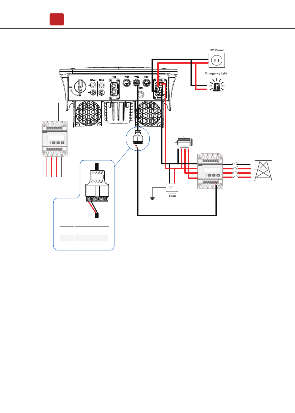
Note:
The Max. power load connects to EPS port should not
exceed the inverter's EPS Max. output power range.
Note:
The wiring terminals should be wrapped with insulation tape,
otherwise it will cause a short circuit and damage the inverter.
Step 2
Step 3
ACL
EPSL EPSN
ACN
PE

Installation
21
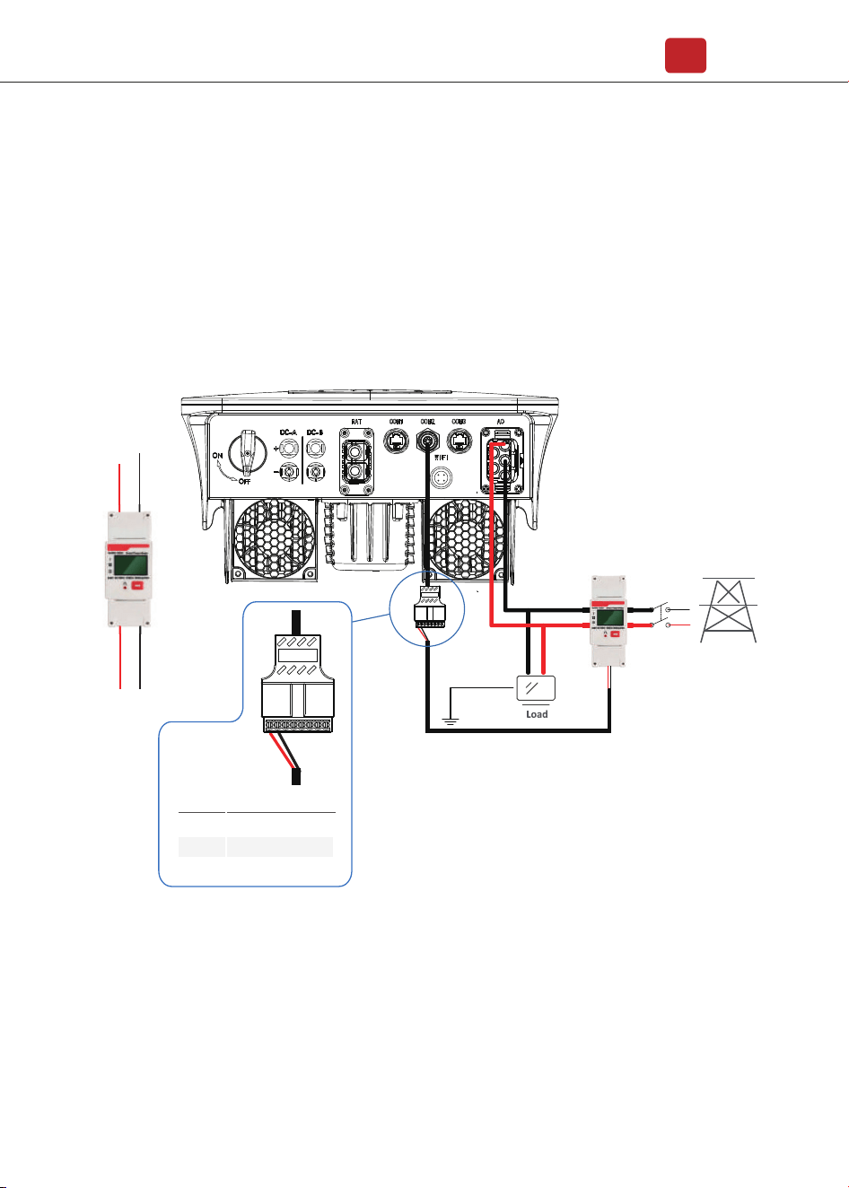
4.3.5
Meter and a current sensor(CT for short below) are used to detect current
power direction of the local load and the grid. The output control function
of the inverters will be activated based on the detected data.
Meter
CT
Install the CT
Grid
CT
Main
Breaker
TV
4 5 6 7 8
PIN Assignment
1PIN 2 3
8
1-6
7 CTU
/
CTN
CT
Installation
22
Install the Meter
1 2 3 4 5 6 7 8
Grid
Inverter
L N
ACL
ACN
PIN Assignment
PIN
3-8
1
2 485 B
485 A
/
Grid
Meter
Main
Breaker
TV
Installation
23
4.4 Communication Connection
The monitoring module could transmit the data to the cloud server, and display
the data on the PC, tablet and smart-phone.
WIFI / Ethernet / GPRS / RS485 communication is applicable to the inverter.
Please refer to "Communication Configuration Instruction" for detailed
instruction.
Install the WIFI / Ethernet / GPRS / RS485 Communication
1 2 3 4 5 6 7 8
Grid
Meter
Three -phase load
Main
Breaker
TV
Grid
Inverter
L3 NL1 L2
ACL
ACN
PIN Assignment
PIN
3-8
1
2
485 B
485 A
/
Installation
24
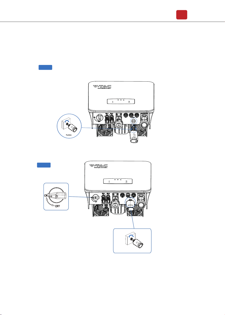
Step 2
Step 1
Turn on the DC switch and AC circuit breaker, and wait until the LED indicator
on the monitoring module flashes, indicating that the monitoring module is
successfully connected.
Wifi/GPRS
Operation
25
5. Operation
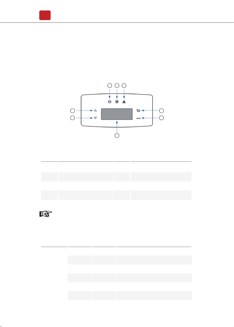
5.1 Control Panel
5
6
1
7
8
2 3 4
Sign Color Explanation
POWER
GreenON
OFF
ON
OFF
ON
OFF
Green
Red
FAULT
The inverter is stand-by
The inverter is power off
The inverter is feeding power
The inverter is not feeding power
Fault occurred
No fault
GRID
Power
Note:
Hold UP/DOWN button can be rolling quickly.
ItemsNo. ItemsNo.
1
2
3
4
LCD Display
BACK Touch Button
UP Touch Button
DOWN Touch Button
5
6
8
7
FAULT LED Indicator
POWER LED Indicator
ENTER Touch Button
GRID LED Indicator
Operation
26
5.3 Inverter Setting
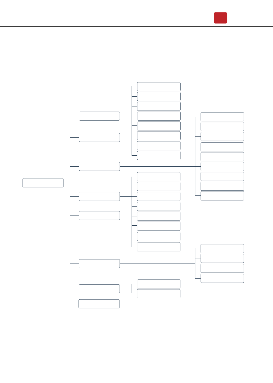
5.2 Menu Overview
Hybrid inverter has a LCD for clearly operating, and menu of the LCD can be
presented as following:
The setting is for Hybrid inverter. Any doubts, please contact distributor
for more details.
PV Info
Bat Info
Run Info
Inv Info
Grid Info
Load Info
EPS Info
Tem Info
Run Record
Display Menu
Running Param
PV Mode
Bat Param
EMS Param
Meter Param
P Mode
Q Mode
Grid Ctrl
Diese1Gen Param
Com Param
Wifi
Parallel
Err Record
Protection Param
Sys Cmd
Safty
Model
Prated
Vrated
Irated
RunTimeDay
RunTimeAll
WIFI SN
Version
Sys Info
Start / Stop
Lang
Safty
Date&Time
System Param
Operation
27
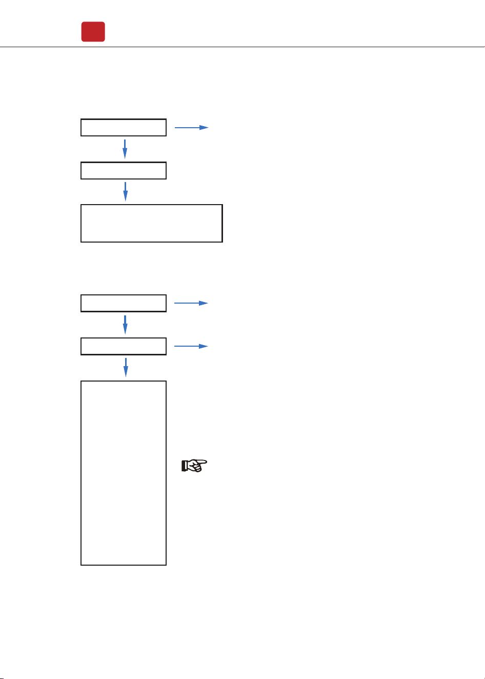
5.3.1 Time & Date
5.3.2 Safety
Sys Param
Date &Time
Date YYYY-MM-DD
Time 24:00:00
Sys Param
Safty
Com-50Hz
Com-60Hz
China
Japan-50
Japan-60
US_240S
US_240D
US_208S
US_208D
Australia
UK-G99
UK-G98
......
System parameters setting
System parameters setting
Safety Specifications
Note:
Select the safty according to the
requirements of the installation site.
Operation
28
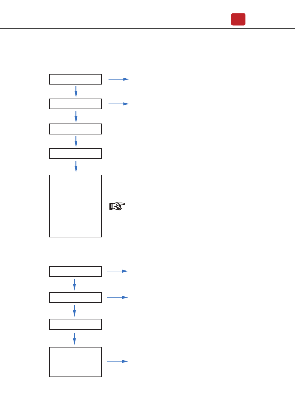
5.3.3
Lithium Battery
Aoboet
ApoLLo
BYD
CALB
Dyness
......
Run Param
Bat Param
Lithium
Operating parameters setting
5432
* * * *
5.3.4 PV Mode
NoPV
Independent
Parallel
Run Param
PV Mode
* * * *
Operating parameters setting
5432
1. No PV connection
2. “Independent” and “Parallel” setting
for professional installers.
Note:
Please select the right battery frand to your use.
Operation
29
5.3.5 Lead Acid
5.3.6
Energy Management System (EMS Param)
SelfUse
Chgfst
SellFst
Maintain
cmdChar
ExtEms
Run Param
Bat Param
LeadAcid
Capacity: 0-1000Ah
* * * *
Run Param
EMS Param
EMS Mode
Energy management
system parameters setting
* * * *
Capacity range (0~1000Ah).
Operating parameters setting
5432
Operating parameters setting
5432
1. Self-Use
2. Back-Up
3. Selling First
4. Maintain (In development)
5. Command charge and discharge
6. External EMS dispatch
Note:
For detailed introduction of each mode, please refer to chapter 3.2 of
the user manual.
Operation
30
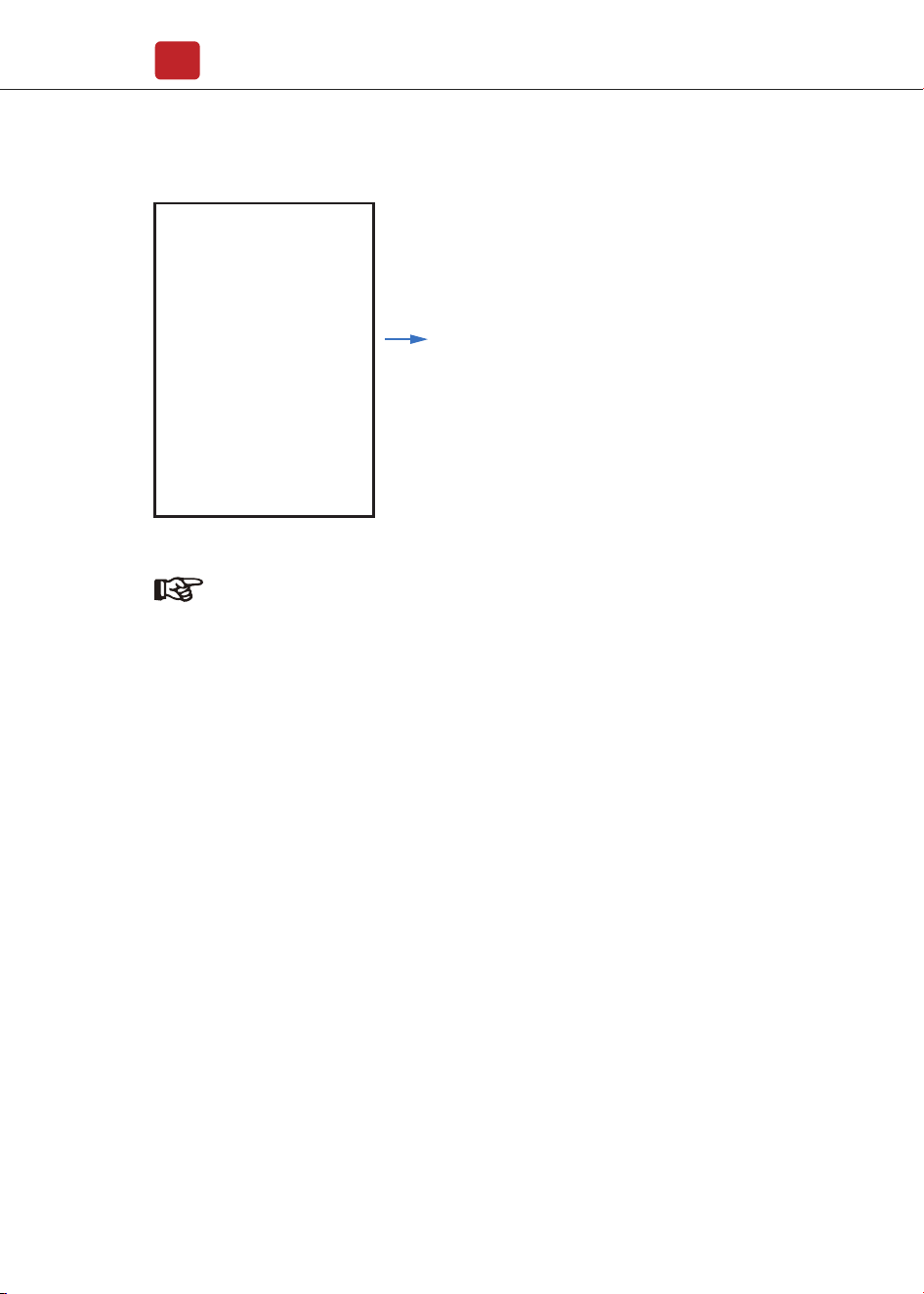
5.3.7 Time of Use
Chg/DChg
Stop
SocMax: 0.0%
SocMin: 0.0%
VBatMax: 0.0V
VBatMin: 0.0V
IChgMax: 0.00A
IDChgMax: 0.00A
PChg: 0W
Charge / discharge.
Charge / discharge power
range -10000W~10000W.
Battery charge / discharge setting.
1. Upper state of charge.
2. Lower state of charge.
3. Battery Overvoltage Threshold.
4. Battery undervoltage threshold.
5. Maximum charging current.
6. Maximum discharge current.
Run Param
EMS Param
Chg Cmd
* * * *
Chg Pwr
Chg Range
Energy management
system parameters setting
Operating parameters setting
5432
Note:
Timed charge and discharge need to complete the three settings
of "Chg Cmd", "Chg Pwr" and "Chg Range", otherwise it will not
work properly.
Operation
31
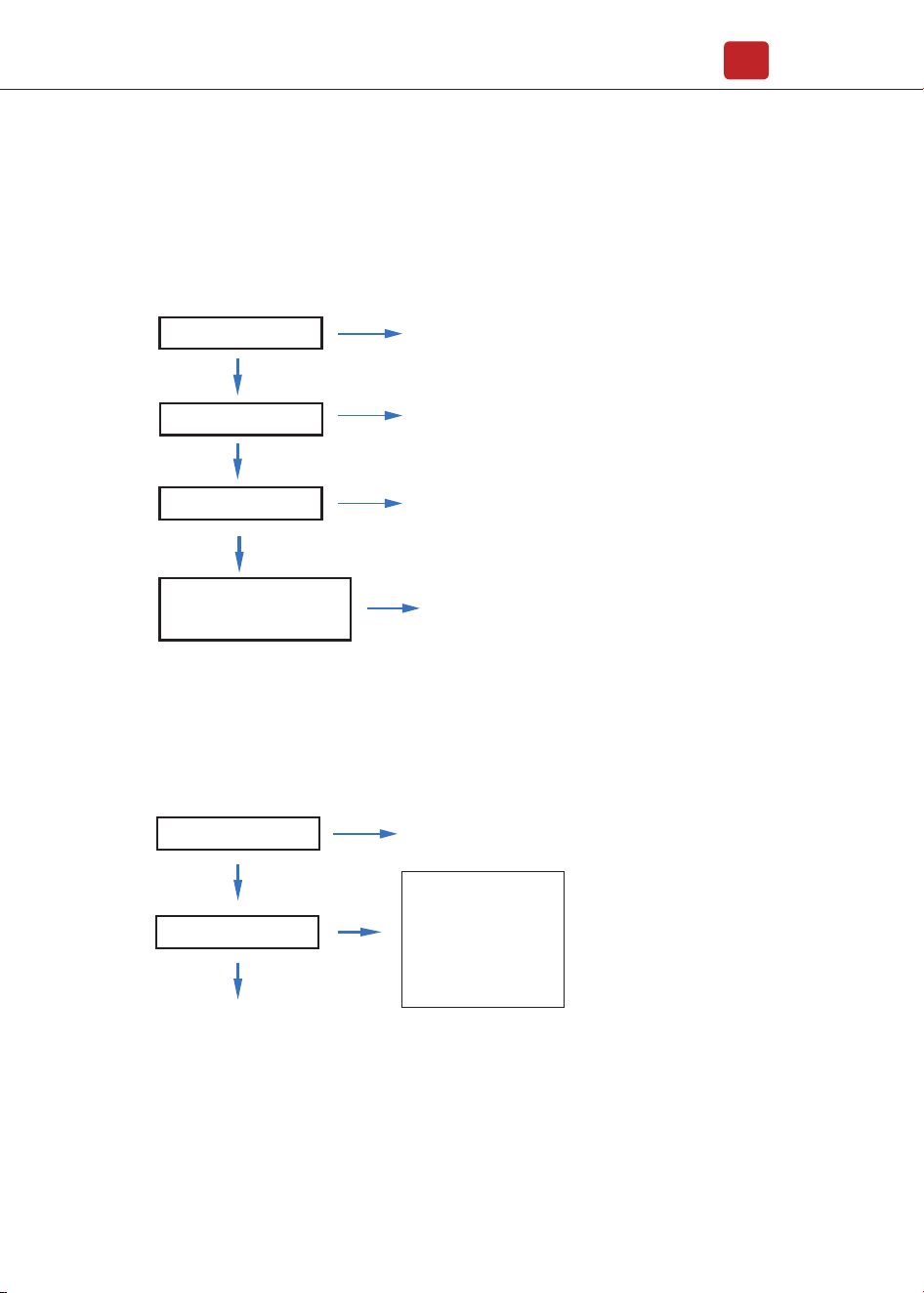
5.3.9
Forced Charging
1. ACChg — AC charging enable.
2. MaxPpct — AC charging Percentage.
3. MaxSoc — AC charging maximum Soc.
4. TimOff1 — AC charging start time1.
5. TimOn2 — AC charging end time 1.
6. AC charging can be set up to three time periods.
5.3.8
AC Charging
ACChg: OFF
MaxPpct: 0.0%
MaxSoc: 0.0%
TimOn1: 00:00
TimOff1: 00:00
TimOn2: 00:00
TimOff2: 00:00
TimOn3: 00:00
TimOff3: 00:00
AC Chg
AC charging
Run Param
EMS Param
* * * *
Energy management
system parameters setting
Operating parameters setting
5432
Run Param
EMS Param
* * * *
Energy management
system parameters setting
Operating parameters setting
5432
Operation
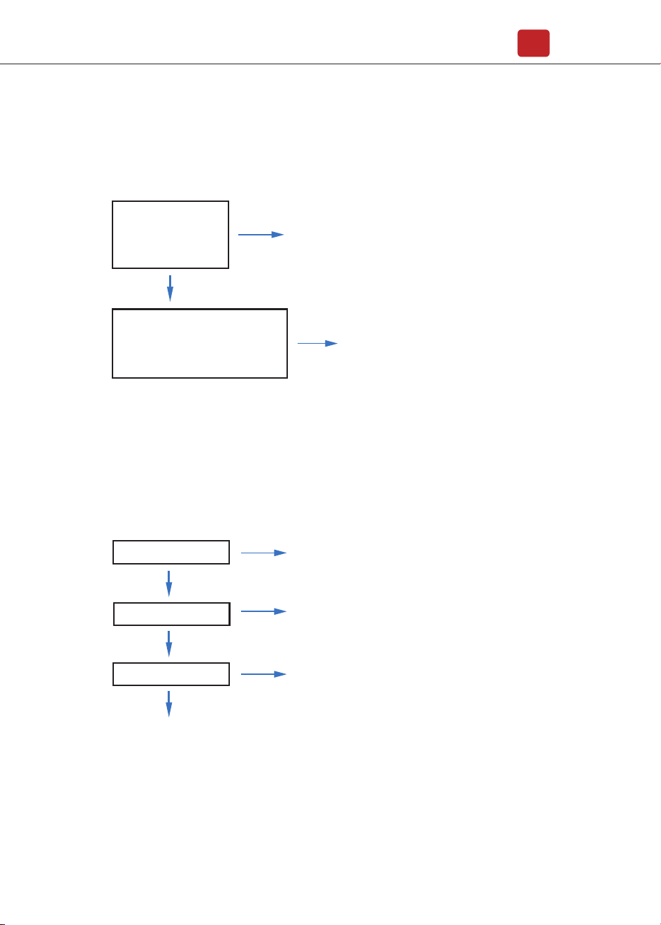
32
ForceChg: ON
PForce: 0.0%
MaxSoc: 0.0V
TimOn1: 00:00
TinOff1: 00:00
TimOn2 : 00:00
TinOff2: 00:00
TimOn3: 00:00
TinOff3: 00:00
Force Chg
5.3.10 Forced Discharging
ForceDChg: ON
PForce: 0.0%
MinSoc: 0.0V
TimOn1: 00:00
TinOff1: 00:00
TimOn2: 00:00
TinOff2: 00:00
TimOn3: 00:00
TinOff3: 00:00
Force DChg
1. ForceDChg — Forced discharging enable.
2. PForce — Forced discharging power percentage.
3. MinSoc — Forced discharging max Soc.
4. TimOn1 — Forced discharging start time 1.
5. TinOff1 — Forced discharging end time 1.
Forced charging
Forced discharge
1. ForceChg — Force charging enable.
2. PForce — Forced charging power percentage.
3. MaxSoc — Forced charging Max Soc.
4. TimOn1 — Forced charging start time 1.
5. TimOff2 — Forced charging end time 1.
6. Forced charging can be set to three time periods .
Run Param
EMS Param
* * * *
Energy management
system parameters setting
Operating parameters setting
5432
Note:
Forced discharging can be set
to three time periods.
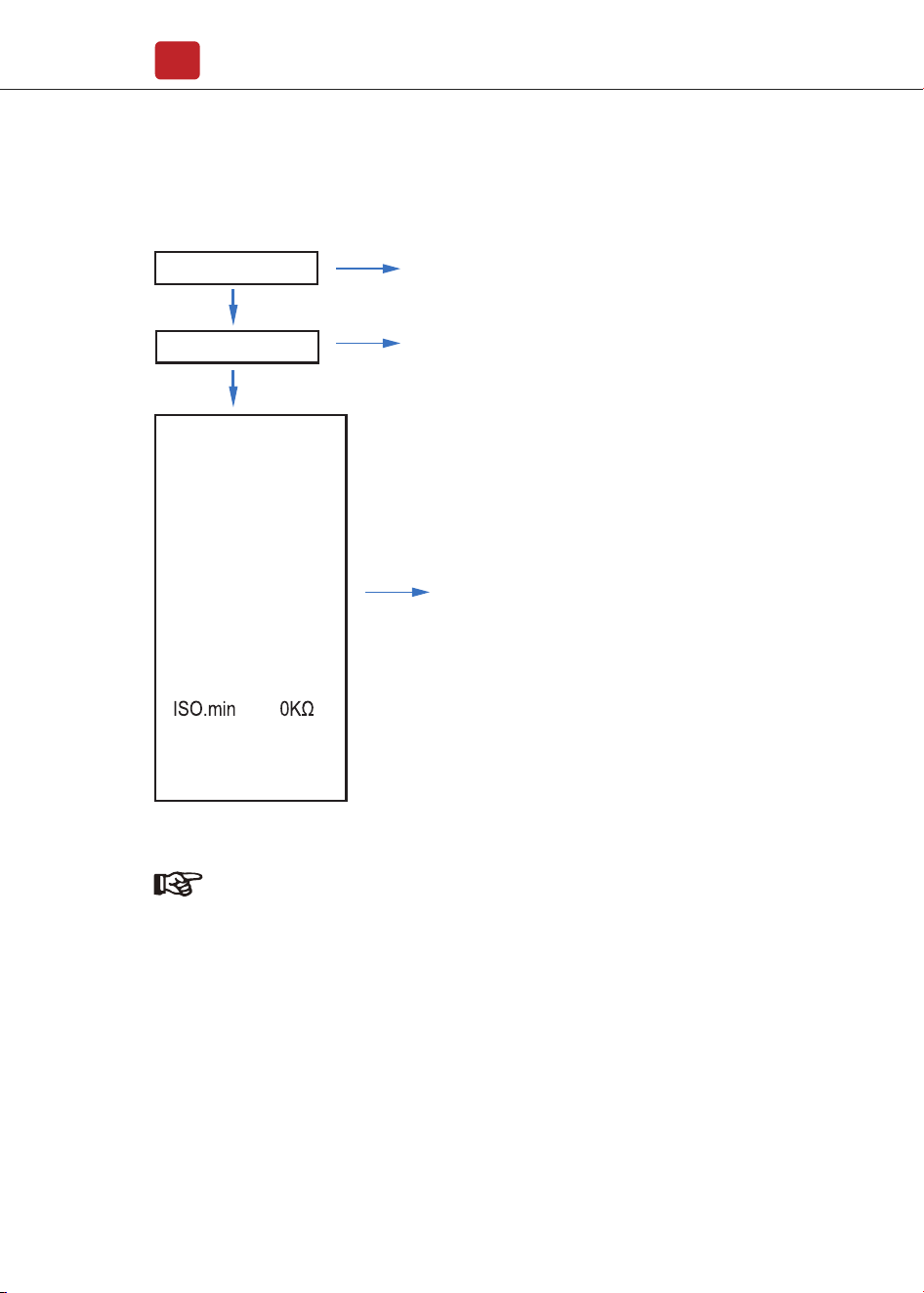
5.3.11 Protection Parameters
Operation
33
IsoChk ON
GfciChk ON
EarthChk ON
V.max 0.0V
V.maxT 0.00S
V.min 0.0V
V.minT 0.00S
F.max 0.00Hz
F.maxT 0.00S
F.min 0.00Hz
F.minT 0.00S
T.conn 0S
T.Reconn 0S
RSSEN ON
1. Insulation resistance detection
2. Leakage current detection
3. Ground detection
4. Voltage upper limit
5. Voltage upper limit time
6. Voltage lower limit
7. Voltage lower limit time
8. Frequency upper limit
9. Frequency upper limit time
10. Frequency lower limit
11. Frequency lower limit time
12. Impedance lower limit
13. Internet time
14. Restart time
15. Restart enable
Run Param
* * * *
Operating parameters setting
5432
Note:
When modifying parameters, you need to pay attention to the unit.
Operation
34
5.3.12 Power grid control
Run Param
Grid Ctrl
* * * *
Operating parameters setting
5432
Power grid control
P%-Feed: 100.0%
P-Feed: 5000W
1. The inverter sends electricity
to the power grid percentage.
2. The inverter is sent to the power
grid power.
5.3.13 Multi-machine in Parallel
Com Param
COM4 Parallel
Communication parameters setting
Meter
Bat
Parallel
Sunspec
Modbus
Operation
34
5.3.14 Diesel Generator Setting (Diese1 Gen Param)
Diese1Gen Param
Diesel generator parameters
Run Param
* * * *
Operating parameters setting
5432
Addr 1
Baud 9600
P Enable ON
Inv_Amout 2-6
M/S Master/Slave
Addr 1
1. Address
2. Band rate
3. Parallel enable
1. Inverter parallel amount
2. Master / Slave
3. Address of slave
4. Only slave can choose address.
Please check the following requirements before testing:
• Installation location is suitable according to Chapter 4.1.3.
• All electrical wires are connected tightly, including PV modules, battery and
AC side(Such as the grid side, EPS side, Gen side).
• Earth line and Smart meter/CT line are connected.
• Hybrid inverters should be set according to the required local grid standard.
• More information please contact with Afore or distributors.
6. Power ON/OFF
Power ON/OFF
35
Diese1Gen GenEn ON
TimeCtr1Em ON
TimeDelay 0S
StarSoc 20.0%
EndSoc 80.0%
TimOn1 00:00
TimOff1 00:00
TimOn2 00:00
TimOff2 00:00
TimOn3 00:00
TimOff3 00:00
Note:
Diesel generator enable and time control enabled must be on,
other wise the diesel generator can not be started.
1. Diese1Gen GenEn — Diesel generator enable.
2. TimeCtr1Em — Time control enable.
3. TimeDelay — Delay time of diesel generator
start working.
4. StarSoc — Battery power percentage when
diesel generator start charging the battery.
5. EndSoc — Battery power percentage when
diesel generator stop charging the battery.
6. TimOn1 — Diesel generator start time 1.
7. TimOff1 — Diesel generator off time 2.

Maintenance&Trouble Shooting
36
• Turn on DC switch.
• After LCD lighting, hybrid inverter should be set following Chapter 5.3 at the
first time.
• When inverter running under normal mode, Running indicator will light up(Ref.
to Chapter 5.1).
• Turn off DC switch ( in hybrid inverter) and all extra-breaker.
7. Maintenance & Trouble Shooting
6.1 Power ON
Periodically maintenance are necessary, please follow steps as below.
• PV connection: twice a year
• AC connection(Grid and EPS) : twice a year
• Battery connection: twice a year
• Earth connection: twice a year
• Heat sink: clean with dry towel once a year
7.1 Maintenance
Restart Hybrid inverter, please follow steps as below:
• Shutdown the inverter Ref. to Chapter6.2.
• Start the inverter Ref. to Chapter 6.1.
6.3 Restart
The fault messages are displayed when fault occurs, please check trouble
shooting table and find related solutions.
7.2 Trouble Shooting
6.2 Power OFF
Note:
Hybrid inverter should be restarted after 5 minutes.
Maintenance&Trouble Shooting
37
Fault Code and Trouble Shooting
Type of Fault
Code Name Description Recommend Solution
PvAfciFaultA03
A04
A05
A06
A07
A08
A09
A10
A11
A12
A13
A14
A15
PV current arcing
• Check PV modules wires and
connectors broken or loose connect, and
then carry out rectification.
• If the fault occurs continuously and
frequently, please ask help for local
distributors.
IsoFaultA02
PvConnectFault
PV Fault
A01
PV connection type
different from setup
• Check PV modules connection
• Check PV Mode setup Ref.
Chapter 5.3.
ISO check among PV
panels/ wires and ground
is abnormal.
• Check PV modules wires, those wires
are soaked or damaged, and then carry
out rectification.
• if the fault occurs continuously and
frequently, please ask help for local
distributors.
Pv1OverVoltFault
Pv2OverVoltFault
Pv3OverVoltFault
Pv4OverVoltFault
Pv5OverVoltFault
Pv6OverVoltFault
Pv7OverVoltFault
Pv8OverVoltFault
Pv9OverVoltFault
Pv10OverVoltFault
-
-
-
PV6ReverseFault
A16
A17
A18
A19
A20
A21
PV1ReverseFault
PV2ReverseFault
PV3ReverseFault
PV4ReverseFault
PV5ReverseFault
PV Voltage over
PV(+) and PV(-) reversed
Connection
• Reconfiguration of PV strings, reduce
the PV number of a PV string to reducing
inverter PV input voltage.
• Suggestion that contacting with local
distributors.
• Check PV(+) and PV(-) Connect
whether reversed or not.
• If reversed, make correction.
Pv12OverVoltFault
Pv11OverVoltFault

Type of Fault
Code Name Description Recommend Solution
A22
A23
A24
A25
A26
A27
A33
A34
A35
A36
A37
A38
A39
A40
A41
A42
A43
A44
A45
A46
A47
A48
A49
A50
A51
A52
A53
A54
A55
A56
PV Fault
PV7ReverseFault
PV8ReverseFault
PV9ReverseFault
PV10ReverseFault
PV11ReverseFault
PV12ReverseFault
Pv1AbnormalFault
Pv2AbnormalFault
Pv3AbnormalFault
Pv4AbnormalFault
Pv5AbnormalFault
Pv6AbnormalFault
Pv7AbnormalFault
Pv8AbnormalFault
Pv9AbnormalFault
Pv10AbnormalFault
Pv11AbnormalFault
Pv12AbnormalFault
Pv13AbnormalFault
Pv14AbnormalFault
Pv15AbnormalFault
Pv16AbnormalFault
Pv17AbnormalFault
Pv18AbnormalFault
Pv19AbnormalFault
Pv20AbnormalFault
Pv21AbnormalFault
Pv22AbnormalFault
Pv23AbnormalFault
Pv24AbnormalFault
PV(+) and PV(-) reversed
Connection
• Check PV modules partial occlusion or
cells damaged.
• Check PV module wires and
connectors broken or loose connect,
then repair it.
Maintenance&Trouble Shooting
38

Maintenance&Trouble Shooting
39
PcsBatTempSensorOpen
PcsBatTempSensorShort
BmsBatSystemFault
BmsBatVolOverFault
BmsBatVolUnderFault
BmsCellVolOverFault
BmsCellVolUnderFault
BmsCellVolUnbanceFau
BatChgCurOverFault
BatDChgCurOverFault
BatTemperatureOverFa
BatTemperatureUnderF
CelTemperatureOverFa
CelTemperatureUnderF
BatIsoFault
BatSocLowFault
BmsInterComFault
BatRelayFault
B07
B08
B09
B10
B11
B12
B13
B14
B15
B16
B17
B18
B19
B20
B21
B22
B23
B24
Type of Fault
Code Name Description Recommend Solution
B01
B02
B03
Battery Fault
PcsBatOverVoltFault
PcsBatUnderVoltFault
PcsBatInsOverVoltFaul
All these faults will be
detected or reported by
battery BMS.
• If specific fault high temperature or low
temperature, then should change battery
installed environment temperature.
• Restart battery, maybe can working as
normal.
• If this fault occurs continuously and
frequently, please ask help for local
distributors.
Battery temperature
sensor abnormal
• Check battery temperature sensor and
connected wires damage or not , then
rectification or change new one.
Battery voltage over or
under
• Check inverters connected battery lines
and connectors broken or loose connect.
• Carry out rectification if broken or
loose.
• Checking battery voltage is abnormal
or not, then maintenance or change new
battery.
B04 PcsBatReversedFault
Bat. (+) and Bat. (-) are
reversed.
• Check Bat.(+) and Bat.(-)connect
reversed or not.
• Make correction If reversed.
B05 PcsBatConnectFault
Battery wires loose
• Check battery wires and connectors
damage or loose connect.
• Carry out rectification if break.
B06 PcsBatComFault
Battery communication
abnormal
• Check battery side communication
wires damage or loose connect, and
then carry out rectification.
• Check battery is off or other abnormal,
then Mastertenance battery or change
new battery.

Maintenance&Trouble Shooting
40
BatPreChaFault
BmsBatChgMosFault
BmsBatDChgMosFault
BMSVolOVFault
BMSVolLFault
VolLockOpenFault
VolLockShortFault
ChgRefOVFault
B25
B26
B27
B28
B29
B30
B31
B32
Type of Fault
Code Name Description Recommend Solution
Battery Fault
GridOverVoltFault
GridUnderVoltFault
GridLineOverVoltFault
GridLineUnderVoltFault
Grid voltage over
Grid voltage under
Grid line voltage over
Grid line voltage under
C05
C06
C07
C08
• The inverter will restart automatically
when the grid three phase return to
normal.
• Contact with local distributor or
required grid company adjust voltage
protection parameters.
C01 GridLossFault
Grid lost (islanding)
• Inverter will restart automatically when
the grid return to normal.
• Check inverter connected with grid
connectors and cable normal or not.
C02 GridUnbalanVoltFault
Grid Voltage unbalanced.
• The inverter will restart automatically
when the grid three phase return to
normal.
• Check inverter connected with the grid
connectors and wires normal or not.con-
nectors and cable normal or not.
C03 GridInstOverVoltFault
Grid instantaneous
voltage over
• The inverter will restart automatically
when the grid three phase return to
normal.
• Contact with local distributor or
required grid company adjust protection
parameters.
C04
Grid10MinOverVoltFault
Grid voltage Over by
10 Minutes
• The inverter will restart automatically
when the grid three phase return to
normal.
• Contact with local distributor or
required grid company adjust 10 minutes
protection voltage parameters.
C10 GridUnderFreqFault
Grid Frequency under
C09 GridOverFreqFault
Grid Frequency over
• The inverter will restart automatically
when the grid three phase return to
normal.
• Contact with local distributor or
required grid company adjust frequency
protection parameters.
Maintenance&Trouble Shooting
41
GenOverVoltFault
GenUnderVoltFault
GenOverFreqFault
GenUnderFreqFault
D03
D04
D05
D06
Pv1HwOverCurrFault
Pv2HwOverCurrFault
Pv3HwOverCurrFault
Pv4HwOverCurrFault
Pv5HwOverCurrFault
Pv6HwOverCurrFault
Pv7HwOverCurrFault
Pv8HwOverCurrFault
Pv9HwOverCurrFault
Pv10HwOverCurrFault
Pv11HwOverCurrFault
Pv12HwOverCurrFault
Pv1SwOverCurrFault
Pv2SwOverCurrFault
Pv3SwOverCurrFault
Pv4SwOverCurrFault
Pv5SwOverCurrFault
Pv6SwOverCurrFault
Pv7SwOverCurrFault
Pv8SwOverCurrFault
GenOverVoltFault
GenUnderVoltFault
GenOverFreqFault
GenUnderFreqFault
E01
E02
E03
E04
E05
E06
E07
E08
E09
E10
E11
E12
E13
E14
E15
E16
E17
E18
E19
E20
Type of Fault
Code Name Description Recommend Solution
D01
Off-grid Fault
DC Fault
UpsOverPowerFault
PV current over, triggered
by Software logic.
• Power off, power on then restart.
• If those faults occurs continuously and
frequently, please ask help for local
distributors.
PV current over, triggered
by hardware protection
circuit
• Power off, then restart (Ref. Chapter8).
• If those faults occurs continuously and
frequently, please ask help for local
distributors.
• Adjust generator running parameters,
make the output voltage, frequency in
allowed range.
• If this fault occurs continuously and
frequently, please ask help for local
distributors.
0ff-grid load over
• Reduce loads.
• If sometimes overload, it can be
ignored, when generation power enough
can be recovery.
• If those faults occurs continuously and
frequently, please ask help for local
distributors.
D02 GridConflictFault
Grid connected to Back-up
terminal
• Check the off-grid port connection
correct, disconnect both off-grid and grid
ports.
Maintenance&Trouble Shooting
42
Pv9SwOverCurrFault
Pv10SwOverCurrFault
Pv11SwOverCurrFault
Pv12SwOverCurrFault
Boost1SelfCheck(boost)Fault
Boost2SelfCheck(boost)Fault
Boost3SelfCheck(boost)Fault
Boost4SelfCheck(boost)Fault
Boost5SelfCheck(boost)Fault
Boost6SelfCheck(boost)Fault
Boost7SelfCheck(boost)Fault
Boost8SelfCheck(boost)Fault
Boost9SelfCheck(boost)Fault
Boost10SelfCheck(boost)Fault
Boost11SelfCheck(boost)Fault
Boost12SelfCheck(boost)Fault
BusHwOverVoltFault
BusHwOverHalfVoltFault
BusSwOverVoltFault
BusSwOverHalfVoltFault
BusSwUnderVoltFault
BusUnbalancedFault
E21
E22
E23
E24
E33
E34
E35
E36
E37
E38
E39
E40
E41
E42
E43
E44
E45
E46
E47
E48
E49
E50
Type of Fault
Code Name Description Recommend Solution
DC Fault
PV boost circuit abnormal
when self checking
• Power off, then restart (Ref. Chapter8).
• If those faults continuously and
frequently, please ask help for local
distributors.
Bus voltage over
• Power off, then restart (Ref. Chapter8).
• If those faults continuously and
frequently, please ask help for local
distributors.
• Power off, then restart (Ref. Chapter8).
• If those faults continuously and
frequently, please ask help for local
distributors.
• Power off, then restart (Ref. Chapter8).
• If those faults continuously and
frequently, please ask help for local
distributors.
Bus voltage under as running
DC Bus voltage unbalanced
Bus Controller current over
Bus Controller abnormal
when self checking
BusBalBridgeHwOver-
CurFault
E51
E52
E53
E54
E55
E56
E57
E58
BDCHwOverCurrFault
BDCSwOverCurrFault
BDCSelfCheckFault
BDCSwOverVoltFault
TransHwOverCurrFault
BiDC abnormal as self checking
BiDC voltage over
BiDC current over
BiDC current over
BusBalBridgeSwOver-
CurFault
BusBalBridgeSelf-
CheckFault
Maintenance&Trouble Shooting
43
Type of Fault
Code Name Description Recommend Solution
AC Fault
• Change fuse.
• Power off, then restart (Ref. Chapter8).
• If those faults continuously and
frequently, please ask help for local
distributors.
BiDC fuse broken
BiDC relay abnormal
BDCFuseFaultE59
E60 BDCRelayFault
R phase current over
S phase current over
T phase current over
On-grid current unbalanced
DC injection current over
• Power off, then restart (Ref. Chapter8).
• If those faults occurs continuously and
frequently, please ask help for local
distributors.
F01
F02
F03
F04
F05
F06
F07
HwOverFault
InvHwOverCurrFault
InvROverCurrFault
InvSOverCurrFault
InvTOverCurrFault
GridUnbalanCurrFault
DcInjOverCurrFault
PLL abnormal
Grid relay abnormal
Ups relay abnormal
Generator relay abnormal
Relay4 abnormal
• Power off, then restart (Ref. Chapter8).
• If those fault occurs continuously and
frequently, please ask help for local
distributors.
F09
F10
F11
F12
F13
PLLFault
GridRelayFault
UpsRelayFault
GenRelayFault
Relay4Fault
Generator current over
F17
F18
F19
GenROverCurrFault
GenSOverCurrFault
GenTOverCurrFault
Off-grid output current over
• When off-grid the load start impulse
current is over, reduce the start impulse
current load.
• Power off, then restart (Ref. Chapter8).
• If those fault occurs continuously and
frequently, please ask help for local
distributors.
• Check generator output voltage,
frequency is stability, and adjust
generator.
• Power off, then restart(Ref. Chapter8).
• If those fault occurs continuously and
frequently, please ask help for local
distributors.
F14
F15
F16
UpsROverCurrFault
UpsSOverCurrFault
UpsTOverCurrFault
Ac over current by protection
hardware
F20
GenReversePowerFault
Active power injected to
generator
All over current/ voltage by
protection hardware
• Check AC insulation and ground wires
connect ground is well or not, then repair
it.
• Power off, then restart (Ref. Chapter8)..
• If those fault occurs continuously and
frequently, please ask help for local
distributors.
Ac side leakage current over
F08 AcOverLeakCurrFault
Maintenance&Trouble Shooting
44
Type of Fault
Code Name Description Recommend Solution
System Fault
AC Fault
• Power off, then restart (Ref. Chapter8).
• If those faults occurs continuously and
frequently, please ask help for local
distributors.
F25
F21
F22
F23
F24
DcInjOverVoltFault
UpsOverVoltFault
UpsUnderVoltFault
UpsOverFreqFault
UpsUnderFreqFault
Sampling hardware
abnormal
• Power off, then restart (Ref. Chapter8).
• If those faults occurs continuously and
frequently, please ask help for local
distributors.
G01
G02
G03
G04
G05
G06
G07
G08
G09
G10
G11
G12
G13
G14
G15
G16
G17
G18
G19
G20
G21
G22
G23
G24
PV1CurAdChanFault
PV2CurAdChanFault
PV3CurAdChanFault
PV4CurAdChanFault
PV5CurAdChanFault
PV6CurAdChanFault
PV7CurAdChanFault
PV8CurAdChanFault
PV9CurAdChanFault
PV10CurAdChanFault
PV11CurAdChanFault
PV12CurAdChanFault
BDCCurrAdChanFault
TransCurAdChanFault
BalBrigCurAdChanFault
RInvCurAdChanFault
SInvCurAdChanFault
TInvCurAdChanFault
RInvDciAdChanFault
SInvDciAdChanFault
TInvDciAdChanFault
LeakCurAdChanFault
VoltRefAdChanFault
UpsRCurAdChanFault
Off-grid DC injection
voltage over
Off-grid output voltage over
or under
Off-grid output frequency
over or under
Maintenance&Trouble Shooting
45
Type of Fault
Code Name Description Recommend Solution
System Fault
Inner Warnning
• Power off, then restart (Ref. Chapter8).
• If those faults occurs continuously and
frequently, please ask help for local
distributors.
• Power off, then restart (Ref. Chapter8).
• If those faults occurs continuously and
frequently, please ask help for local
distributors.
• Remove foreign matter logged in fan.
• If those faults occurs continuously and
frequently, please ask help for local
distributors.
• Change or improve the installation
environment temperature, make running
temperature suitable.
• Power off, then restart (Ref. Chapter8).
• If those faults occurs continuously and
frequently, please ask help for local
distributors.
G37
TempAdChanFault
G25
G26
G27
G28
G29
G30
G31
G32
UpsSCurAdChanFault
UpsTCurAdChanFault
GenRCurAdChanFault
GenSCurAdChanFault
GenTCurAdChanFault
UpsRDcvAdChanFault
UpsSDcvAdChanFault
UpsTDcvAdChanFault
G41
G42
G43
G44
G45
G46
G47
EnvirOverTempFault
EnvirLowTempFault
CoolingOverTempFault
CoolingLowTempFault
OverTemp3Fault
LowTemp3Fault
CpuOverTempFault
All temperature sensors
abnormal
G38
VoltAdConflictFault
The sample value of PV,
battery and BUS voltage
inconsistent
G39
CPUAdConflictFault
The sample value between
master CPU and slaver
CPU inconsistent
G40
PowerCalcConflictFault
Power value between PV,
battery and AC output
inconsistent
G48
ModelConflictFault Version conflict with inverter
Installation environment
temperature over or low
I01
I02
I03
InterFanWarning
ExterFanWarning
Fan3Warning
Fan abnormal
Cooling temperature over
or low
Temperature3 over or low
CPU temperature over
Specifications
47
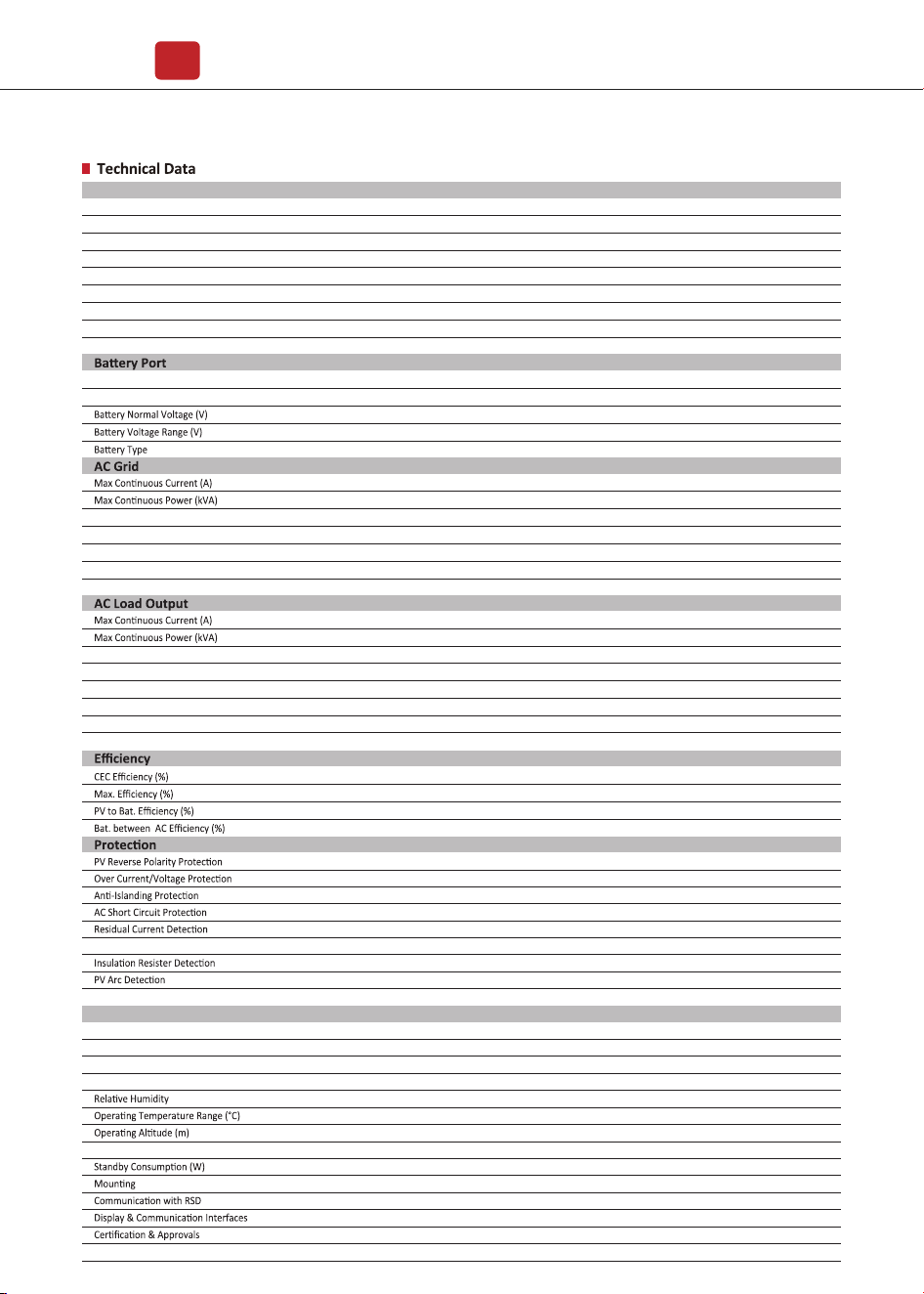
8. Specifications
370 x 535 x 192
18.5
Transformerless
Intelligent Fan
0 - 100 %
- 25 to 60
< 4000
< 25
< 10
Wall Bracket
SUNSPEC
LCD, LED, RS485, CAN, Wi-Fi, GPRS, 4G
NRS097, G98�G99, EN50549-1, C10�C11, AS4777.2, VDE-AR-N4105, VDE0126, IEC62109-1, IEC62109-2
EN61000-6-2, EN61000-6-3
Yes
Yes
Yes
Yes
Yes
Yes
Yes
Yes
IP65 � NEMA4X
97.0
97.6
98.1
96.8
550
80 - 500
360
100
18.5 x 2
26 x 2
2 � 2
198 to 242 @ 220 � 207 to 253 @ 230
50 � 60
0.999 (Adjustable from 0.8 overexcited to 0.8 underexcited)
< 3
220 � 230
50 � 60
Seamless
< 3
51.2
40 - 60
Li-ion � Lead-acid etc.
110 - 500
17.0
3.6
24.6 � 23.5
5.4
5.4
17.0
3.6
16.4 � 15.7
3.6
80
General Data
Ground Fault Monitoring
Enclosure Protect Level
Max. Input Power (kW)
Max. PV Voltage (V)
MPPT Range (V)
Full MPPT Range (V)
Normal Voltage (V)
Startup Voltage (V)
Max. Input Current (A)
Max. Short Current (A)
No. of MPP Tracker � No. of PV String
PV Input
Nominal Grid Current (A)
Nominal Grid Voltage (V)
Nominal Grid Frequency (Hz)
Power Factor
Current THD (%)
Max Peak Current (A) (10min)
Max Peak Power (kVA) (10min)
Nominal AC Voltage L-N (V)
Nominal AC Frequency (Hz)
Switching Time (ms)
Voltage THD (%)
Max. Charge�Discharge Power (kW)
Max. Charge�Discharge Current (A)
Dimensions (W x H x D, mm)
Weight (kg)
Topology
Cooling
Noise Emission (dB)
EMC
Maintenance&Trouble Shooting
46
Communication between
master inverter and slaver
ones abnormal in parallel
mode
Type of Fault
Code Name Description Recommend Solution
Outside
Warnning
• The warnings are not matter influence.
• Power off, then restart (Ref. Chapter8).
• If those faults occurs continuously and
frequently, please ask help for local
distributors.
• Check the smart meter model,
connection or connectors are correct,
any loose.
• if abnormal, repair or change.
• Power off, then restart (Ref. Chapter8).
• If those faults occurs continuously and
frequently, please ask help for local
distributors.
• Check Meter/CT connection, installed
place, and installed direction.
• if abnormal, re-installation.
• Power off, then restart (Ref. Chapter8).
• If this those faults continuously and
frequently, please ask help for local
distributors.
• Power off, then restart (Ref. Chapter8).
• If this those faults continuously and
frequently, please ask help for local
distributors.
I04
EnvirTempAdChan-
Warning
I07
I08
ExtFlashComWarning
EepromComWarning
Flash abnormal
Eeprom abnormal
I10
I11
HmiComWarning
FreqCalcConflictWarning
HMI abnormal
Frequency value abnormal
I05
CoolingTempAdChan-
Warning
Some temperature sensors
abnormal
Communication between
slaver CPU and master
CPU abnormal
I06
Temp3AdChanWarning
I09
SlaveComWarning
I12
UnsetModel
Running model is not initial
J01
MeterComWarning Meter/CT abnormal
J02
MeterConnectWarning
Wires connecting type of
meter wrong
• Check earth line connection or earth
connecting impedance.
• if abnormal, then adjust it.
• Power off, then restart (Ref. Chapter8).
• If this those faults continuously and
frequently, please ask help for local
distributors.
• Check parallel connect communi-
cation wires damage, connectors loose,
connect port correct or not.
• if not, then adjust it.
• Power off, then restart (Ref. Chapter8).
• If this those faults continuously and
frequently, please ask help for local
distributors.
J04
GndAbnormalWarning
Earth impedance over by
cable loose and so on
J05
ParallelComWarning
• Contact with Battery manufacturer.
J03
SohWarning
Battery SOH low
•
Contact with local distributor.
Inner Warnning