USE ONLY HAYWARD GENUINE REPLACEMENT PARTS
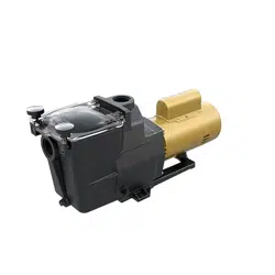
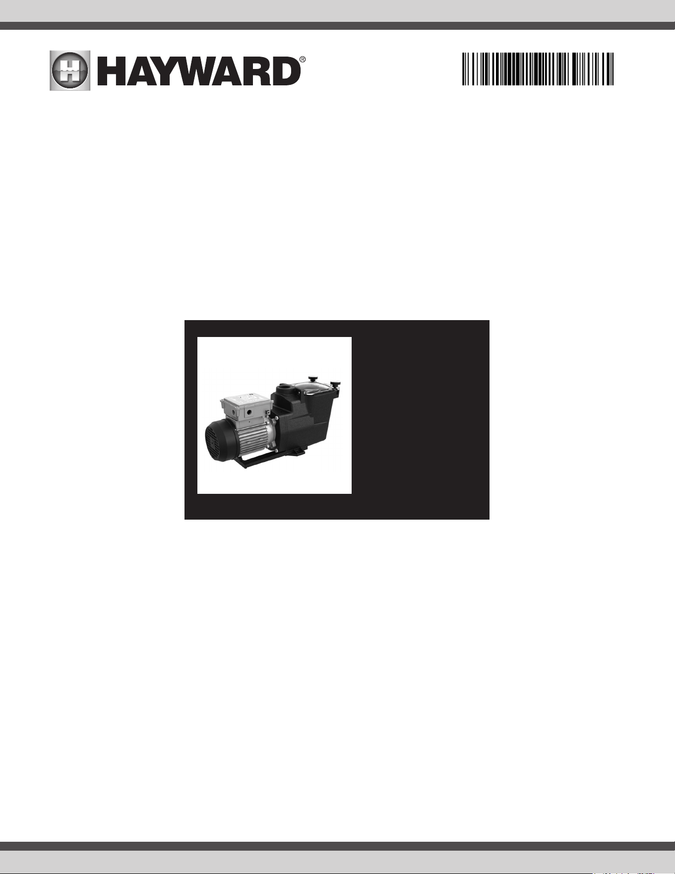
Super Pump Series
SP2670007X10
SP2600X5
SP2605X7
SP2607X10
SP2607X102S
Contents
Safety Instructions..........1
Overview........................4
Installation.....................5
Operation......................6
Maintenance..................7
Winterization.................7
Sha Seal Change...........8
Replacement Parts..........9
Troubleshooting............10
Warranty.......................14
Hayward Industries, Inc.
1 Hayward Industrial Drive
Clemmons, NC 27012
Phone: (908) 355-7995
www.hayward.com
®
IS26002 RevA
USE ONLY HAYWARD GENUINE REPLACEMENT PARTS
1
WARNING - READ AND FOLLOW ALL INSTRUCTIONS in this owner’s
manual and on the equipment. Failure to follow instructions can cause severe injury and/or death.
WARNING – This product should be installed and serviced only by a qualied professional.
CAUTION – All electrical wiring MUST be in conformance with all applicable local codes, regulations, and
the National Electric Code (NEC).
USE OF NON-HAYWARD REPLACEMENT PARTS VOIDS WARRANTY.
ATTENTION INSTALLER - THIS MANUAL CONTAINS IMPORTANT INFORMATION ABOUT THE INSTALLATION,
OPERATION, AND SAFE USE OF THIS VARIABLE SPEED PUMP THAT MUST BE FURNISHED TO THE END
USER OF THIS PRODUCT. FAILURE TO READ AND FOLLOW ALL INSTRUCTIONS COULD RESULT IN SERI-
OUS INJURY.
WARNING – To reduce risk of injury, do not permit children to use or climb on this product. Closely su-
pervise children at all times. Components such as the ltration system, pumps, and heaters must be positioned to
prevent children from using them as a means of access to the pool.
CAUTION – This pump is intended for use on permanently installed swimming pools and may also be used
with hot tubs and spas if so marked. Do NOT use with storable pools. A permanently installed pool is constructed in
or on the ground or in a building such that it cannot be readily disassembled for storage. A storable pool is construct-
ed so that it is capable of being readily disassembled for storage and reassembled to its original integrity. Though
this product is designed for outdoor use, it is strongly advised to protect the electrical components from the weather.
Select a well-drained area, one that will not ood when it rains. It requires free circulation of air for cooling. Do not
install in a damp or non-ventilated location. If installed within an outer enclosure or beneath the skirt of a hot tub or
spa, adequate ventilation and free circulation of air must be provided to prevent overheating of the motor.
SAVE THESE INSTRUCTIONS
Basic safety precautions should always be followed, including the following: Failure to follow instructions can
cause severe injury and/or death.
This is the safety-alert symbol. When you see this symbol on your equipment or in this manual, look for
one of the following signal words and be alert to the potential for personal injury.
WARNING warns about hazards that could cause serious personal injury, death or major property dam-
age and if ignored presents a potential hazard.
CAUTION warns about hazards that will or can cause minor or moderate personal injury and/or prop-
erty damage and if ignored presents a potential hazard. It can also make consumers aware of actions that are
unpredictable and unsafe.
The NOTICE label indicates special instructions that are important but not related to hazards.
Important Safety Instructions
USE ONLY HAYWARD GENUINE REPLACEMENT PARTS
2
WARNING – Pool and spa components (seals, gaskets, etc.) have a nite life. All components should be
inspected frequently and replaced at least every ten years, or if found to be damaged, broken, cracked, missing, or
not securely attached.
WARNING – Risk of Electric Shock. All electrical wiring MUST be in conformance with applicable local
codes, regulations, and the National Electric Code (NEC). Hazardous voltage can shock, burn, and cause death
or serious property damage. To reduce the risk of electric shock, do NOT use an extension cord to connect unit to
electric supply. Provide a properly located electrical receptacle. Before working on pump or motor, turn o power
supply to the pump.
WARNING – To reduce the risk of electric shock replace damaged wiring immediately. Locate conduit to
prevent abuse from lawn mowers, hedge trimmers and other equipment.
WARNING – Risk of Electric Shock. In accordance with the National Electric Code (NEC), connect only
to a branch circuit protected by a ground-fault circuit-interrupter (GFCI). Contact a qualied electrician if you cannot
verify that the circuit is protected by a GFCI. The unit must be connected only to a supply circuit that is protected
by a ground-fault circuit-interrupter (GFCI). Such a GFCI should be provided by the installer and should be tested
on a routine basis. To test the GFCI, push the test circuit button. The GFCI should interrupt power. Push the reset
button. Power should be restored. If the GFCI fails to operate in this manner, the GFCI is defective. If the GFCI in-
terrupts power to the pump without the test button being pushed, a ground current is owing, indicating the possibil-
ity of an electric shock. Do not use this pump. Disconnect the pump and have the problem corrected by a qualied
service representative before using.
WARNING – Failure to bond pump to pool structure will increase risk for electrocution and could result in
injury or death. To reduce the risk of electric shock, see installation instructions and consult a professional electri-
cian on how to bond pump. Also, contact a licensed electrician for information on local electrical codes for bonding
requirements.
Notes to electrician: Use a solid copper conductor, size 8 or larger. Run a continuous wire from external bonding
lug to reinforcing rod or mesh. Connect a No. 8 AWG (8.4 mm2) [No. 6 AWG (13.3 mm2) for Canada] solid copper
bonding wire to the pressure wire connector provided on the pump housing and to all metal parts of swimming pool,
spa, or hot tub, and to all electrical equipment, metal piping (except gas piping), and conduit within 5 ft. (1.5 m) of
inside walls of swimming pool, spa, or hot tub. IMPORTANT - Reference NEC codes for all wiring standards includ-
ing, but not limited to, grounding, bonding and other general wiring procedures.
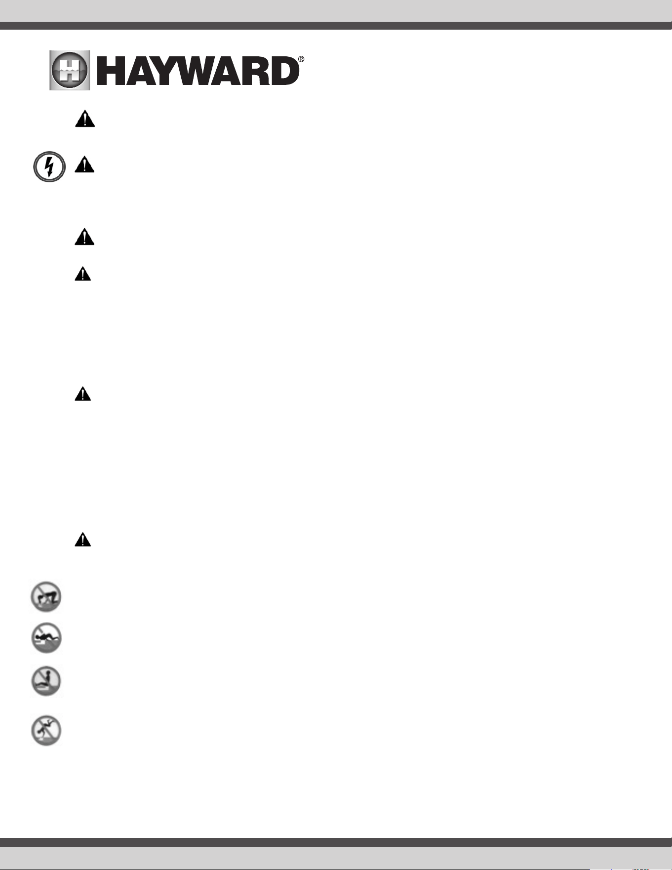
WARNING – Suction Entrapment Hazard. Suction in suction outlets and/or suction outlet covers, which
are damaged, broken, cracked, missing, or unsecured cause severe injury and/or death due to the following entrap-
ment hazards (symbols complements of APSP):
Hair Entrapment - Hair can become entangled in suction outlet cover.
Limb Entrapment - A limb inserted into an opening of a suction outlet sump or suction outlet cover that is damaged,
broken, cracked, missing, or not securely attached can result in a mechanical bind or swelling of the limb.
Body Suction Entrapment - A dierential pressure applied to a large portion of the body or limbs can result in an
entrapment.
Evisceration/ Disembowelment - A negative pressure applied directly to the intestines through an unprotected
suction outlet sump or suction outlet cover which is damaged, broken, cracked, missing, or unsecured can result in
evisceration/disembowelment.
Mechanical Entrapment - There is potential for jewelry, swimsuits, hair decorations, ngers, toes, or knuckles to be
caught in an opening of a suction outlet cover resulting in mechanical entrapment.
USE ONLY HAYWARD GENUINE REPLACEMENT PARTS
3
WARNING – To Reduce the risk of Entrapment Hazards:
• When outlets are small enough to be blocked by a person, a minimum of two functioning suction outlets per
pump must be installed. Suction outlets in the same plane (i.e. oor or wall), must be installed a minimum of
three feet (3’) [0.91 meter] apart, as measured from near point to near point.
• Dual suction ttings shall be placed in such locations and distances to avoid “dual blockage” by a user.
• Dual suction ttings shall not be located on seating areas or on the backrest for such seating areas.
• The maximum system ow rate shall not exceed the values shown in the “Pipe Sizing Chart” found in section 4.3
below.
• Never use pool or spa if any suction outlet component is damaged, broken, cracked, missing, or not securely
attached.
• Replace damaged, broken, cracked, missing, or not securely attached suction outlet components immediately.
• In addition to two or more suction outlets per pump installed in accordance with latest APSP standards and
CPSC guidelines, follow all national, state, and local codes applicable.
• Installation of a vacuum release or vent system, which relieves entrapping suction, is recommended.
WARNING – Hazardous Pressure. Pool and spa water circulation systems operate under hazardous
pressure during start-up, normal operation, and after pump shut-o. Stand clear of circulation system equipment
during pump start-up. Failure to follow safety and operation instructions could result in violent separation of the
pump housing and cover due to pressure in the system, which could cause property damage, severe personal injury,
or death. Before servicing pool and spa water circulation system, all system and pump controls must be in o posi-
tion and lter manual air relief valve must be in open position. Before starting pump, all system valves must be set in
a position to allow system water to return back to the pool. Do not change lter control valve position while pump is
running. Before starting pump, fully open lter manual air relief valve. Do not close lter manual air relief valve until
a steady stream of water (not air or air and water mix) is discharged from the valve. All suction and discharge valves
MUST be OPEN when starting the circulation system. Failure to do so could result in severe personal injury and/or
property damage.
WARNING – Separation Hazard. Failure to follow safety and operation instructions could result in violent
separation of pump components. Strainer cover must be properly secured to pump housing with strainer cover lock
ring. Before servicing pool and spa circulation system, all system and pump controls must be in o position and
lter manual air relief valve must be in open position. Do not operate pool and spa circulation system if a system
component is not assembled properly, damaged, or missing. Do not operate pool and spa circulation system unless
lter manual air relief valve body is in locked position in lter upper body. All suction and discharge valves MUST be
OPEN when starting the circulation system. Failure to do so could result in severe personal injury and/or property
damage.
WARNING – Never operate the circulation system at more than 50 PSI maximum.
WARNING – Fire and burn hazard. Motors operate at high temperatures and if they are not properly iso-
lated from any ammable structures or foreign debris they can cause res, which may cause severe personal injury
or death. It is also necessary to allow the motor to cool for at least 20 minutes prior to maintenance to minimize the
risk for burns.
WARNING – Failure to install according to dened instructions may result in severe personal injury or
death.
SAVE THESE INSTRUCTIONS
USE ONLY HAYWARD GENUINE REPLACEMENT PARTS
4
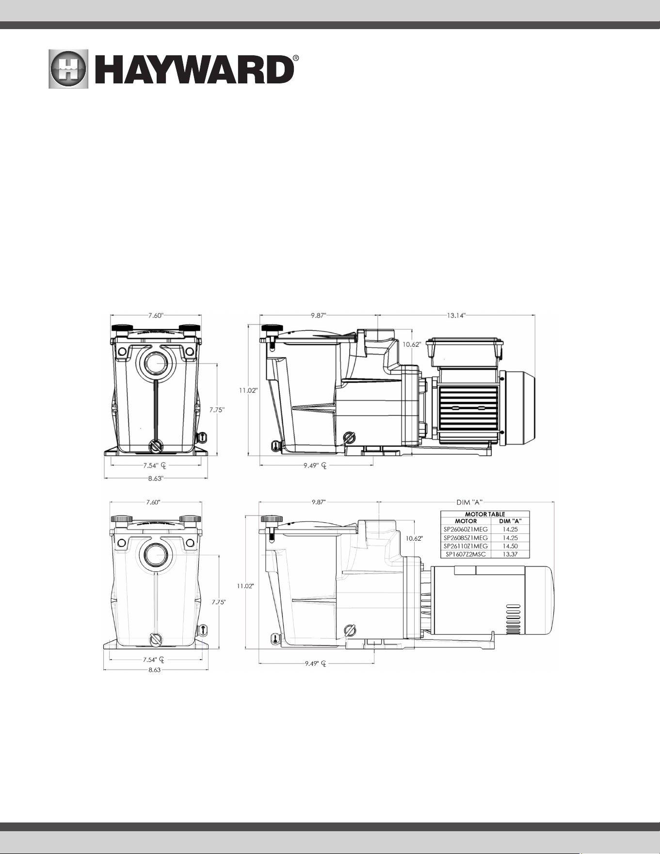
Overview
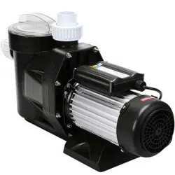
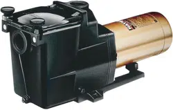
This manual contains information for the proper installation and operation of the Hayward Super Pump
®
700 Series and MUST be followed precisely.
• Super-sized 110 cubic-inch basket has extra leaf-holding capacity and extends time between cleanings. Rigid construction with load extender ribbing
assures free flowing operation even with heavy debris loads.
• Exclusive swing-aside hand knobs make strainer cover removal simple and easy.
• See-thru strainer cover lets you see when the basket needs cleaning.
• All components molded of corrosion-proof reinforced thermoplastic for extra durability and long life.
• Uni-bracket mounting base provides stable, stress-free support, plus versatility for any installation requirement. Adapts to 48 and 56 frame motors.
• Heat resistant, industrial size ceramic seal.
• Rugged, one-piece housing, with full-flow ports, assures rapid priming and continuous operation.
• Service-ease design gives simple access to all internal parts. By disengaging just four (4) bolts, motor and entire drive group assembly can be removed,
without disturbing pipe or mounting connections.
USE ONLY HAYWARD GENUINE REPLACEMENT PARTS
5
Installation
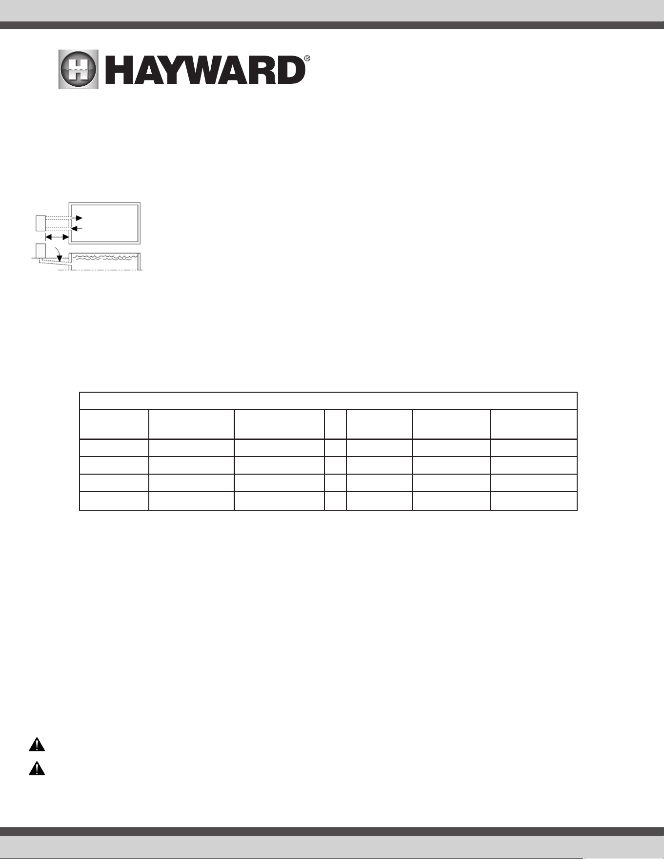
Pump Location and Mounting
Locate pump as close to the pool as possible, in compliance with local codes. To reduce friction loss, suction lines should run as direct as they can be. Suction
lines should have continuous slope upward from lowest point in line. Joints must be tight (but not over-tightened). Suction line diameter must equal or be larger
than the discharge line diameter.
Though the pump is designed for outdoor use, it is advised to place pump and filter in the shade to shield them from continu-
ous direct heat. Select a well-drained area that will not flood when it rains. Do NOT install pump and filter in a damp or non-
ventilated location. Keep motor clean. Pump motors require free circulation of air for cooling.
Install pump on a level concrete slab or other rigid base to meet all local and national codes. Secure pump to base with screws
or bolts to further reduce vibration and stress on pipe or hose joints. The base must be level, rigid, and vibration free.
Pump mount must:
• Allow use of short, direct suction pipe (to reduce friction losses).
• Allow for ball valves in suction and discharge piping.
• Be protected from excess moisture and flooding.
• Allow adequate access for servicing pump and piping.
• Incorporate a straight portion of pipe prior to pump inlet no less than (5) pipe diameters in length.
Pipe Sizing Chart
Note: System design should allow a maximum of 8-ft/sec [2.44 meters/sec] water velocity in residential pool or spa piping. It is recommended that a minimum
length of piping, equivalent to 10 pipe diameters, be used between the pump suction inlet and any plumbing fittings.
Plumbing
When pump is installed in 1.5” pipe diameter system, use supplied bushing kit. Use PTFE tape to seal threaded connections on molded plastic components. All
plastic fittings must be new or thoroughly cleaned before use. NOTE - Do NOT use Plumber’s Pipe Dope as it may cause cracking of the plastic components.
When applying PTFE tape to plastic threads, wrap the entire threaded portion of the male fitting with one to two layers of tape. Wind the tape clockwise as you
face the open end of the fitting, beginning at the end of the fitting. The pump suction and outlet ports have molded-in thread stops. Do NOT attempt to force hose
connector fitting past this stop. It is only necessary to tighten fittings enough to prevent leakage. Tighten fitting by hand and then use a tool to engage fitting an
additional 1 ½ turns. Use care when using PTFE tape as friction is reduced considerably; do NOT over-tighten fitting or you may cause damage. If leaks occur,
remove connector, clean off old PTFE tape, re-wrap with one to two additional layers of PTFE tape, and re-install connector.
Fittings
Fittings restrict flow. For better efficiency, use the fewest possible fittings. Avoid fittings that could cause an air trap. Use two or more suction outlets per pump
installed in accordance with latest ASME, APSP Standards and CPSC guidelines, follow all National, State, and Local codes applicable.
Electrical
WARNING – All electrical wiring MUST conform to local codes, regulations, and the National Electric Code (NEC).
WARNING – Ground and bond pump before connecting to electrical power supply. Failure to ground and bond pump can cause serious or fatal
electrical shock hazard. Do NOT ground to a gas supply line. To avoid dangerous or fatal electrical shock, turn OFF power to pump before working on electrical
MAXIMUM RECOMMENDED SYSTEM FLOW RATE BY PIPE SIZE
Pipe Size
in. [mm]
Flow Rate
GPM [LPM]
Water Velocity
ft/sec [m/s]
Pipe Size
in. [mm]
Flow Rate
GPM [LPM]
Water Velocity
ft/sec [m/s]
1½” 50.8 8 2½” 119 8
[50] [192] [2.44] [75] [452] [2.44]
2” 84 8 3” 184 8
[63] [317] [2.44] [90] [698] [2.44]
USE ONLY HAYWARD GENUINE REPLACEMENT PARTS
6
connections. Fire Hazard - match supply voltage to pump nameplate voltage. Insure that the electrical supply available agrees with the pump’s voltage, phase,
and cycle, and that the wire size is adequate for the amps rating and distance from the power source. Use copper conductors only.
Electrical Specs
Refer to motor nameplate for voltage and current ratings. Use copper conductors only. For indoor & outdoor use. Connect pump to an appropriately sized/rated
branch circuit protector in accordance with local codes, regulations, and the National Electric Code (NEC). A disconnecting means located at least 5 ft. from the
inside wall of the pool, spa, or hot tub must be provided.
Voltage
Voltage at pump MUST NOT be more than 10% above or below nameplate rated voltage, or components may overheat, causing overload tripping and reduced
component life. If voltage is less than 90% or more than 110% of rated voltage when pump is running at full load, consult the power company.
Grounding and Bonding
1. Install, ground, bond, and wire pump in accordance with local or national electrical code requirements.
2. Permanently ground pump. Use green ground terminal provided under access plate; use size and type wire required by code. Connect ground terminal
to electrical service ground.
3. Bond pump to pool structure. Bonding will connect all metal parts within and around the pool with a continuous wire. Bonding reduces the risk of a current
passing between bonded metal objects, which could potentially cause electrical shock if grounded or shorted. Reference NEC codes for all wiring standards
including, but not limited to, grounding, bonding and general wiring procedures.
4. Use a solid copper conductor, size 8 or larger. Run wire from external bonding lug to reinforcing rod or mesh. Connect a No. 8 AWG (8.4 mm
2
) [No. 6 AWG
(13.3 mm
2
) for Canada] solid copper bonding wire to the pressure wire connector provided on the motor housing and to all metal parts of swimming pool,
spa, or hot tub, and to all electrical equipment, metal piping (except gas piping), and conduit within 5 ft. (1.5 m) of inside walls of swimming pool, spa, or
hot tub.
Wiring
WARNING – All electrical wiring MUST conform to local codes, regulations, and National Electric Code (NEC). Pump MUST be permanently con-
nected to circuit. Connect pump to an appropriately sized/rated branch circuit protector in accordance with local codes, regulations, and the National Electric
Code (NEC). Use the circuit breaker as the master On-Off switch.
Operation
WARNING – Separation Hazard - Failure to Open all suction and discharge valves could result in severe personal injury. To avoid OPEN all
suction and discharge valves, as well as filter air relief valve (if available) on filter, when starting the circulating pump system.
Starting/Priming the Pump
Pumps with single speed motors are self priming to 10 ft. and pumps with 2 speed motors are self priming to 10 ft. onhigh speed only. Fill strainer housing with
water to suction pipe level. If water leakage occurs from anywhere on the pump or filter, DO NOT start the pump. If no leakage occurs, stand at least 10 feet
from pump and/or filter and proceed with starting the pump.
WARNING – Separation Hazard - Failure to close the filter’s manual air relief valve until a steady stream of water (not air or air and water) is
discharged from valve could result in severe personal injury. To avoid, wait for a steady stream of water.
NOTICE – Never Operate The Pump Without Water. Water acts as a coolant and lubricant for the mechanical shaft seal. NEVER run pump dry. Running
pump dry may damage seals, causing leakage, flooding, and voids warranty. Fill strainer housing with water before starting motor.
USE ONLY HAYWARD GENUINE REPLACEMENT PARTS
7
NOTICE – Before removing strainer cover:
1. STOP PUMP before proceeding.
2. CLOSE VALVES in suction and outlet pipes.
3. RELEASE ALL PRESSURE from pump and piping system using filter manual air relief valve. See filter owner’s manual for more details.
4. If water source is higher than the pump, pump will prime itself when suction and outlet valves are opened. If water source is lower than the pump, unscrew
and remove strainer cover; fill strainer housing with water.
5. Clean and lubricate strainer cover O-ring with “Jack’s 327” each time it is removed. Inspect O-ring and re-install on strainer cover.
6. Replace strainer cover on strainer housing; turn strainer cover hand knobs clockwise to tighten cover. NOTE - Tighten strainer cover knobs by hand only
(no wrenches).
7. OPEN VALVES in suction and outlet pipes.
Before re-starting pump, see “Starting/Priming the Pump” instructions.
NOTICE – Wait five (5) seconds before re-starting pump. Failure to do so may cause reverse rotation of motor and consequent serious pump damage.
Turn on power and wait for pump to prime, which may take up to ten (10) minutes. Priming time will depend on vertical length of suction lift and horizontal
length of suction pipe. If pump does NOT prime within five minutes, stop motor and determine cause. Be sure all suction and discharge valves are open when
pump is running. See Troubleshooting Guide.
Maintenance
• Clean strainer basket regularly. Do NOT strike basket. Inspect cover gasket regularly and replace as necessary.
• Hayward pumps have self-lubricating motor bearings and shaft seals. No lubrication is necessary.
• Keep motor clean. Keep motor air vents free of obstructions to avoid damage. Do NOT use water to hose off motor.
• Occasionally, shaft seals must be replaced, due to wear or damage. Replace with genuine Hayward seal assembly kit. See “Shaft Seal Change Instructions”
in this manual.
Winterization / Storage
WARNING – Separation Hazard. Do not purge the system with compressed air. Purging the system with compressed air can cause components
to explode, with risk of severe injury or death to anyone nearby. Use only a low pressure (below 5 PSI), high volume blower when air purging the pump, filter,
or piping.
NOTICE – Allowing the pump to freeze with water in it will void the warranty.
NOTICE – Use ONLY propylene glycol as antifreeze in your pool/spa system. Propylene glycol is non-toxic and will not damage plastic system compo-
nents; other anti-freezes are highly toxic and may damage plastic components in the system.
Drain all water from pump and piping when expecting freezing temperatures or when storing pump for a long time (see instructions below). Keep motor dry and
covered during storage. To avoid condensation/corrosion problems, do NOT cover or wrap pump with plastic film or bags.
WARNING – Electrical Hazard - Failure to disconnect power may result in serious personal injury or death. To avoid, turn OFF power to motor
before draining pump.
1. Drain water level below all inlets to the pool.
2. Remove drain plugs from bottom of strainer body, and remove strainer cover from strainer housing.
3. Disconnect pump from mounting pad, wiring system (after power has been turned OFF), and piping system.
4. Once the pump is drained of water, re-install the strainer cover and drain plugs. Store pump in a dry area.

USE ONLY HAYWARD GENUINE REPLACEMENT PARTS
8
Shaft Seal Change Instructions
WARNING – Electrical Hazard - Failure to disconnect power may result in serious personal injury or death. To avoid, turn OFF power to motor
before servicing pump.
NOTICE – Only qualified personnel should attempt rotary seal replacement. Contact your local authorized Hayward Dealer or service center if you have
any questions.
Exercise extreme care in handling both the rotating and the stationary sections of the two-part replacement seal. Foreign matter or improper handling will easily
scratch the graphite and ceramic sealing surfaces.
Removing the Motor Assembly
(See Parts Diagram on page 9 of this manual for pump component locations).
1. Remove the four (4) 3/8” x 2” housing cap screws which hold the motor assembly to the pump/strainer housing.
2. Slide the motor assembly out of the pump/strainer housing, exposing the diffuser. Pull the diffuser off of the seal plate, exposing the impeller (The diffuser
may remain in the pump/strainer housing. To remove, pull it straight out of the pump/strainer housing).
Removing the Impeller
(See Parts Diagram on page 9 of this manual for pump component locations).
3. If necessary, remove the motor end cover by removing the two (2) screws or pry off the cap covering the motor shaft. TEFC motors do not require the motor
end cover to be removed to access the shaft end.
4. To prevent motor shaft from turning, depending on which motor you have, secure shaft using a flat blade screwdriver, 1/4” hex driver , or 7/16” wrench on
the motor shaft through the motor fan shroud.
5. Rotate the impeller counterclockwise and remove. The spring portion of the seal assembly is now exposed. Note carefully the position of the spring seal,
and remove it. NOTE - Replace motor cover to protect delicate motor parts if it was removed earlier.
Removing the Ceramic Seat
(See Parts Diagram on page 9 of this manual for pump component locations).
6. Remove the seal plate. Note the tabs on the sides of the plate and the mating grooves on the front of the motor mounting plate.
7. Press the ceramic seat with rubber cup out of the seal plate. If tight, use a small screwdriver to tap seal out.
STOP - Clean all recesses & parts to be reassembled. Inspect gaskets & replace if necessary.
Seal Installation
(See Parts Diagram on page 9 of this manual for pump component locations).
8. Clean and lightly lubricate the impeller hub and seal recess in the seal plate with a dilute solution of non-granulated liquid-type soap.
9. Gently wipe the black, polished surface of the spring seal assembly with a clean, soft, cotton cloth. Press the spring seal assembly onto the impeller hub –
black polished surface facing away from the impeller.
10. Gently wipe the polished surface of the ceramic seal with a clean, soft, cotton cloth. Lubricate the rubber cup on the ceramic seat and press it firmly and
evenly into the recess of the seal plate – polished side facing out.
Replacing the Impeller and Diffuser
(See Parts Diagram on page 9 of this manual for pump component locations).
11. Place the seal plate onto the motor mounting plate, aligning the tabs on the seal plate with the grooves on the motor mounting plate.
12. Screw the impeller onto the motor shaft in a clockwise direction. Tighten snugly by holding motor shaft with screwdriver as noted in step #4.
13. Place the diffuser over the impeller onto the seal plate fitting positioning lug between the two (2) guides.
Replacing the Motor Assembly
(See Parts Diagram on page 9 of this manual for pump component locations).
14. Fasten motor end cover by using the two (2) hex shaped screws. Slide the motor assembly with the diffuser in place, into pump/strainer housing, being
careful not to disturb the diffuser gasket.
15. Fasten assembly to pump/strainer housing using the four (4) 3/8”” x 2” housing cap screws. (Be sure housing gasket is in place, and replace if damaged).
Tighten alternately and evenly.
USE ONLY HAYWARD GENUINE REPLACEMENT PARTS
9
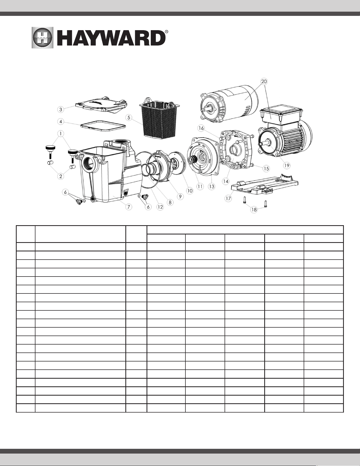
Replacement Parts
REF # Description # Req’d
Part Number
SP2670007X10 SP2600X5 SP2605X7 SP2607X10 SP2607X102S
1 Hand Knob 2 SPX1600P SPX1600P SPX1600P SPX1600P SPX1600P
2 Swivel Nut 2 SPX1600N SPX1600N SPX1600N SPX1600N SPX1600N
3 Strainer Cover 1 SPX1600D SPX1600D SPX1600D SPX1600D SPX1600D
4 Strainer Cover Gasket 1 SPX1600S SPX1600S SPX1600S SPX1600S SPX1600S
5 Basket 1 SPX1600M SPX1600M SPX1600M SPX1600M SPX1600M
6 Drain Plug with Gasket 2 SPX4000FG SPX4000FG SPX4000FG SPX4000FG SPX4000FG
7 Pump / Strainer Housing 1 SPX1620AA SPX1620AA SPX1620AA SPX1620AA SPX1620AA
8 Diffuser Gasket 1 SPX1600R SPX1600R SPX1600R SPX1600R SPX1600R
9 Diffuser 1 SPX2600B SPX2600B SPX2600B SPX2600B SPX2600B
10 Impeller 1 SPX2607C SPX2600C SPX2605C SPX2607C SPX2607C
11 Seal Assembly 1 SPX1600Z2VIT SPX1600Z2 SPX1600Z2 SPX1600Z2 SPX1600Z2
12 Housing Gasket 1 SPX1600T SPX1600T SPX1600T SPX1600T SPX1600T
13 Seal Plate 1 SPX2600E5 SPX2600E5 SPX2600E5 SPX2600E5 SPX2600E5
14 Motor Mounting Plate 1 SPX1600F5 SPX1600F5 SPX1600F5 SPX1600F5 SPX1600F5
15 Housing Cap Screw 4 SPX1600Z4 SPX1600Z4 SPX1600Z4 SPX1600Z4 SPX1600Z4
16 Motor Cap Screw 4 SPX0125Z4 SPX0125Z4 SPX0125Z4 SPX0125Z4 SPX0125Z4
17 Mounting Foot (includes screws - item #18) 1 SPX2600GV SPX2600G1 SPX2600G1 SPX2600G1 SPX2600G1
18 Mounting Foot Cap Screw 2 SPX1600J SPX1600J SPX1600J SPX1600J SPX1600J
19 Slinger 1 SPX0125F SPX0125F SPX0125F SPX0125F SPX0125F
20 Motor (includes slinger - item #19) 1 SPX2607Z1MTG SPX1600Z1M SPX1605Z1M SPX1607Z1M SPX1607Z2MSC
NOTE: SPX2600CAP1 is the replacement capacitor set for SP2670007X10 built with the SP2607Z1MTG motor. SPX2600CAP3 is the replacement capacitor for SP2670007X10 built with the
SP26110Z1MTG motor.”

USE ONLY HAYWARD GENUINE REPLACEMENT PARTS
10
Troubleshooting
Motor Will NOT Start – Check For:
Make sure the terminal board connections agree with the wiring diagram on motor data plate label. Be sure motor is wired for available field supply voltage.
1. Improper or loose wiring connections; open switches or relays; tripped circuit breakers, GFCI’s, or blown fuses.
Solution: Check all connections, circuit breakers, and fuses. Reset tripped breakers or replace blown fuses.
2. Manually check rotation of motor shaft for free movement and lack of obstruction.
Solution: Refer to Steps 4 & 5 of “Shaft Seal Change Instructions” in this manual.
3. If you have a timer, be certain it is working properly. Bypass it if necessary.
Motor Shuts OFF – Check For:
1. Low voltage at motor or power drop (frequently caused by undersized wiring or extension cord use).
Solution: Contact qualified professional to check that the wiring gauge is heavy enough.
NOTE - Your Hayward pump motor is equipped with an “automatic thermal overload protector.” The motor will automatically shut off if power supply drops before
heat damage can build up causing windings to burn out. The “thermal overload protector” will allow the motor to automatically restart once the motor has cooled.
It will continue to cut On/Off until the problem is corrected. Be sure to correct cause of overheating.
Motor Hums, But Does NOT Start – Check For:
1. Impeller jammed with debris.
Solution: Have a qualified repair professional open the pump and remove the debris.
Pump Won’t Prime, Check For:
1. Empty pump/strainer housing.
Solution: Make sure pump/strainer housing is filled with water and cover o-ring is clean. Ensure o-ring is properly seated in the cover o-ring groove.
Ensure o-ring is lubricated with “Jack’s 327” and that strainer cover is locked firmly in position. Lubricant will help to create a tighter seal.
2. Loose connections on suction side.
Solution: Tighten pipe/union connections. NOTE - Any self-priming pump will not prime if there are suction air leaks. Leaks will result in bubbles
emanating from return fittings on pool wall.
3. Leaking O-ring or packing glands on valves.
Solution: Tighten, repair, or replace valves.
4. Strainer basket or skimmer basket loaded with debris.
Solution: Remove strainer housing cover or skimmer cover, clean basket, and refill strainer housing with water. Tighten cover.
5. Suction side clogged.
Solution: Contact a qualified repair professional. Block off to determine if pump will develop a vacuum. You should have 5”-6” of vacuum at the
strainer cover (Only your pool dealer can confirm this with a vacuum gauge). You may be able to check by removing the skimmer basket and holding
your hand over the bottom port with skimmer full and pump running. If no suction is felt, check for line blockage.
a. If pump develops a vacuum, check for blocked suction line or dirty strainer basket. An air leak in the suction piping may be the cause.
b. If pump does not develop a vacuum and pump has sufficient “priming water”:
i. Re-check strainer housing cover and all threaded connections for suction leaks. Check if all system hose clamps are tight.
ii. Check voltage to ensure that the motor is rotating at full RPM’s.
iii. Open housing cover and check for clogging or obstruction in suction. Check impeller for debris.
iv. Remove and replace shaft seal only if it is leaking.
Low Flow – Generally, Check For:
1. Clogged or restricted strainer or suction line.
Solution: Contact a qualified repair professional.
2. Undersized pool piping.
Solution: Correct piping size.
3. Plugged or restricted discharge line of filter, valve partially closed (high gauge reading).
Solution: Sand filters – backwash as per manufacturer’s instructions; D.E. filters – backwash as per manufacturer’s instructions; Cartridge filters –
clean or replace cartridge.
4. Air leak in suction (bubbles issuing from return fittings).
Solution: Re-tighten using PTFE tape.
5. Plugged, restricted, or damaged impeller.
Solution: Replace including new seal assembly.

USE ONLY HAYWARD GENUINE REPLACEMENT PARTS
11
Noisy Pump – Check For:
1. Air leak in suction piping, cavitation caused by restricted or undersized suction line or leak at any joint, low water level in pool, and unrestricted discharge
return lines.
Solution: Correct suction condition or throttle return lines, if practical. Holding hand over return fitting will sometimes prove this point or putting in a
smaller eyeball fitting.
2. Vibration due to improper mounting, etc.
Solution: Mount the pump on a level surface and secure the pump to the equipment pad.
3. Foreign matter in pump housing. Loose stones/debris hitting impeller could be cause.
Solution: Clean the pump housing.
4. Motor bearings noisy from normal wear, rust, overheating, or concentration of chemicals causing seal damage which will allow chlorinated water to seep
into bearings wiping out the grease causing bearing to whine.
Solution: All seal leaks should be replaced at once.

USE ONLY HAYWARD GENUINE REPLACEMENT PARTS
12

USE ONLY HAYWARD GENUINE REPLACEMENT PARTS
13

USE ONLY HAYWARD GENUINE REPLACEMENT PARTS
14
HAYWARD
®
Pool Products Limited Warranty
To original purchasers of this equipment, Hayward Pool Products, Inc. warrants its products to be
free from defects in materials and workmanship for a period of TWO (2) years from the date of
purchase, when used in single family residential applications.
The limited warranty excludes damage from freezing, negligence, improper installation, improper
use or care or any Acts of God. Parts that fail or become defective during the warranty period shall
be repaired or replaced, at our option, within 90 days of the receipt of defective product, barring
unforeseen delays, without charge.
Proof of purchase is required for warranty service. In the event proof of purchase is not available,
the manufacturing date of the product will be the sole determination of the purchase date.
To obtain warranty service, please contact the place of purchase or the nearest Hayward Auth
rized Service Center. For assistance on your nearest Hayward Authorized Service Center please
visit us at www.hayward.com.
Hayward shall not be responsible for cartage, removal, repair or installation labor or any other
such costs incurred in obtaining warranty replacements or repair.
The Hayward Pool products warranty does not apply to components manufactured by others. For
such products, the warranty established by the respective manufacturer will apply.
The express limited warranty above constitutes the entire warranty of Hayward Pool Products with
respect to its’ pool products and is in lieu of all other warranties expressed or implied, including
warranties of merchantability or fitness for a particular purpose. In no event shall Hayward Pool
products be responsible for any consequential, special or incidental damages of any nature.
Some states do not allow a limitation on how long an implied warranty lasts, or the exclusion of
incidental or consequential damages, so the above limitation may not apply to you. This warranty
gives you specific legal rights, and you may also have other rights, which vary from state to state.
Hayward Pool Products
400 Connell Drive, Suite 6100
Berkeley Heights, NJ 07922
*Supersedes all previous publications.

USE ONLY HAYWARD GENUINE REPLACEMENT PARTS
LifeStar XE is a registered trademark of
Hayward Industries, Inc. © 2022 Hayward Industries, Inc.
All other trademarks not owned by Hayward are the property of their respective owners.
Hayward is not in any way affiliated with or endorsed by those third parties.