Model:PSP150PM / PSP200PM / PSP300PM
INSTRUCTION MANUAL
VARIABLE SPEED POOL PUMP


CONTENTS
1. General
2. Pump Fixing
3. Installation of the pipes
4. Electrical Installation
5. Check before first starting the pump
6. Starting the pump
7. Function
8. Servicing
9. Problems and Solutions
10. Guarantee
11. Technical data of pumps
12. Wiring
·························· ··············· · 3
······················· ···· ······· ··· 4
· · ········· · ····· · · · ······ 5
· · ········· · ······ · · ····· ··· 5
· · ······· ····· 6
················· ···· ···· · · ···· 6
······················· · ················· 7
······················· ················· 10
·························· 10
······················ · ···· · ··· ······ 11
················· ········ 11
·························· ··············· · 12
2
This appliance can be used by children aged from 8 years and above and persons with reduced physical,
sensory or mental capabilities or lack of experience and knowledge if they have been given supervision
or instruction concerning use of the appliance in a safe way and understand the hazards involved.
If the appliance or the supply cord is damaged, it must be repaired by manufacturer, its service agent or
qualified person.
Children shall not play with the appliance.
Cleaning and user maintenance shall not be made by children without supervision.
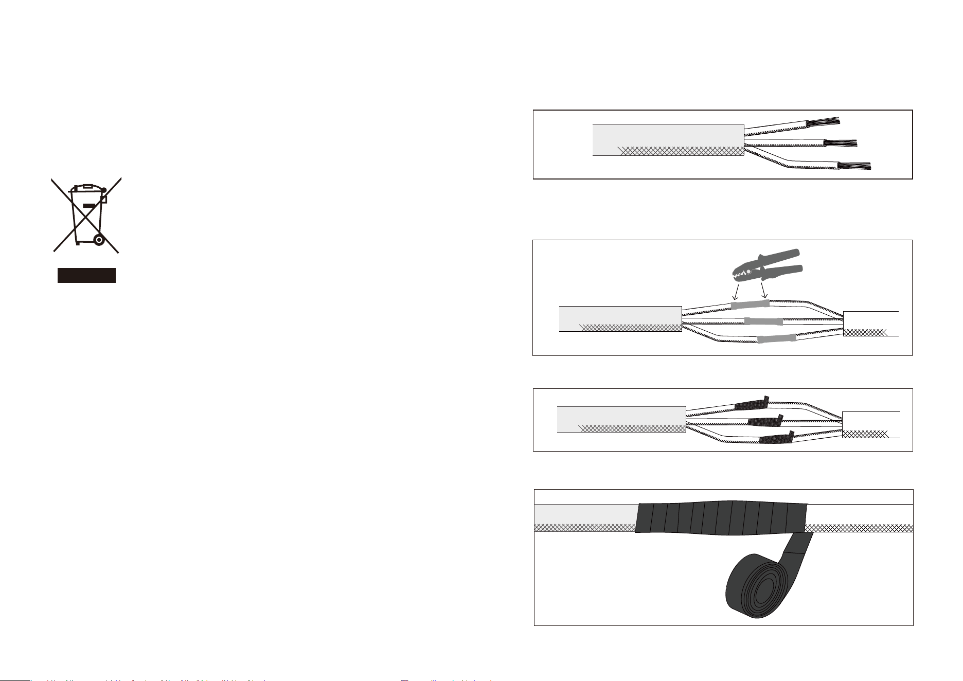
Meaning of crossed out wheeled dustbin: Do not dispose of electrical appliances
as unsorted municipal waste, use separate collection facilities.
Contact you local government for information regarding the collection systems
available.
If electrical appliances are disposed of in landfills or dumps, hazardous substanc-
es can leak into the groundwater and get into the food chain, damaging your
health and well-being. When replacing old appliances with new ones, the retailer
is legally obligated to take back your old appliance for disposals at least free of
charge.
Aention!
This manual is an essential guide for the safe operation and maintenance of the Aquastrong Variable
Speed Pool Pump. It includes vital safety information, so please read the instructions carefully before
use. Adherence to safe practices and reasonable care is paramount. We are grateful for your choice of
the Aquastrong Variable Speed Pool Pump and trust that it will serve you well, oering long-lasting
performance and exceptional reliability. Your feedback is valuable to us; feel free to contact us with any
suggestions. We will thoughtfully consider your input and respond, whether we implement your
suggestions or not. Your support is greatly appreciated.
Please note that all data, diagrams, and specifications in this manual are subject to the latest product
information. In case of any discrepancy between the manual and the nameplate, the nameplate should
be referred to as the authoritative source.
Introduction
This manual oers comprehensive guidance on the installation, operation, and maintenance of our
pumps, essential for ensuring safe and eective usage.
We advise thorough reading and retention for future reference.
Our swimming pool pumps, designed for permanent installation in pools, are horizontal, self-priming
centrifugal units. The incorporation of a non-return valve facilitates immediate priming. To ensure
optimal performance, the water temperature should not surpass 95°F. Our pump materials have been
rigorously tested for hydraulic eiciency and electrical safety. Prior to installation, it is critical to review
this manual thoroughly. Installation must adhere to prevailing industry standards. We absolve ourselves
of any liability resulting from non-compliance with these installation instructions. Adherence to the
provided electrical wiring diagrams is recommended to prevent overloading the pump motor.
1. General
3
1. Peel o the black cable skin to reveal the 3 wires inside, strip each cable by 2/3 inch with a wire stripper,
then strip the insulation to reveal 1/5 inch copper wire.Prepare the pump wire extension, repeat the above
steps.
2. Insert the stripped wires into the bu connectors in the wire pigtail from the pump. Firmly crimp each
splice with crimping plier to tightly hold the wires In place. Aention: Please pay aention to correct match-
ing when wiring an extension cable.
3. Winding the waterproof electrical tape on the bu splice connections of three strands of wire.
4. Winding the waterproof electrical tape over wire.
12. Wiring
Black - Hot Wire (110V); White - Hot Wire (110V); Green - Ground Wire
12
10. Guarantee
Our pumps are warranted against material and manufacturing defects for a period of 24 months from
the date of delivery. This warranty does not cover wear parts, gaskets, covers, and the filtering basket.
Compliance with the assembly and/or maintenance manual is required for the warranty to be valid. In the
event of a warranty claim, presentation of the purchase invoice is mandatory. Under this warranty, the
vendor's sole obligation is to repair or replace, free of charge, any product or component recognized as
defective by the vendor’s technical services. All other expenses related to the warranty claim, including
but not limited to transportation costs, shall be borne by the purchaser. To qualify for warranty service,
the product must be approved by the vendor's after-sales service prior to any repair or replacement.
This warranty does not cover any visible defects, damages due to normal wear, incorrect assembly,
misuse, or unauthorized modifications to the product. For any inquiries or clarification regarding this
warranty, please contact our after-sales service at [email protected].
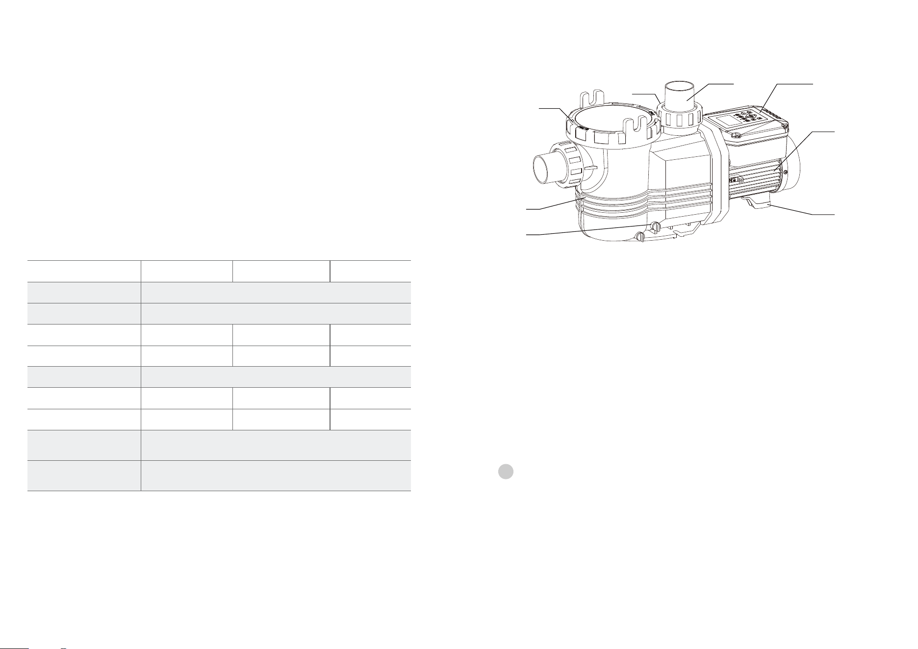
11. Technical data of pumps
Technical date
PSP150PM
5 A
1.5 HP
8189 GPH
65 ft
PSP200PM
220-240V
50Hz/60Hz
7.2 A
2 HP
IPX5/ Class F
10566 GPH
75 ft
104°F (40°C)
122°F (50°C)
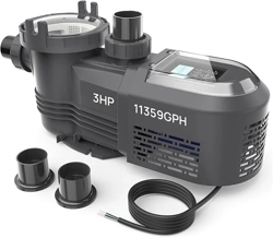
PSP300PM
9.5 A
3 HP
11359 GPH
80 ft
Votagles
Frequency
Rate current
HP
Protection/insulation
Max. Flow rate
Maximum Ambient
Temperatuer
Maximum Liquid Ambient
Temperatuer
Max. Head
11
Caution:
!
For example:
2. Pump Fixing
This appliance is not intended for use by persons (including children) with reduced physical, sensory or
mental capabilities, or lack of experience and knowledge, unless they have been given supervision or
instruction concerning use of the appliance by a person responsible for their safety. Children should be
supervised to ensure that they do not play with the appliance.
The pump must not be used when people are in the water.
Caution for Pump Installation: Ensure the pump is protected from moisture and potential flooding. It's
recommended not to install the pump more than 3 meters above the water level to ensure optimal
performance.
Regardless of the pump's height above the water and the capacity of the chosen model, be aware that
priming can take several minutes. Install the pump and its components in a dry, well-ventilated area to
prevent environmental damage and ensure the longevity and safe operation of the pump. Adequate
measures should be taken to safeguard the pump against environmental factors.
1
2
3
4
5
6
7
8
1. Plug screw 2.Pump body 3.Filter Cover
6.Terminal box 7. Motor 5. Connection
4.Nut
8. Support foot
4
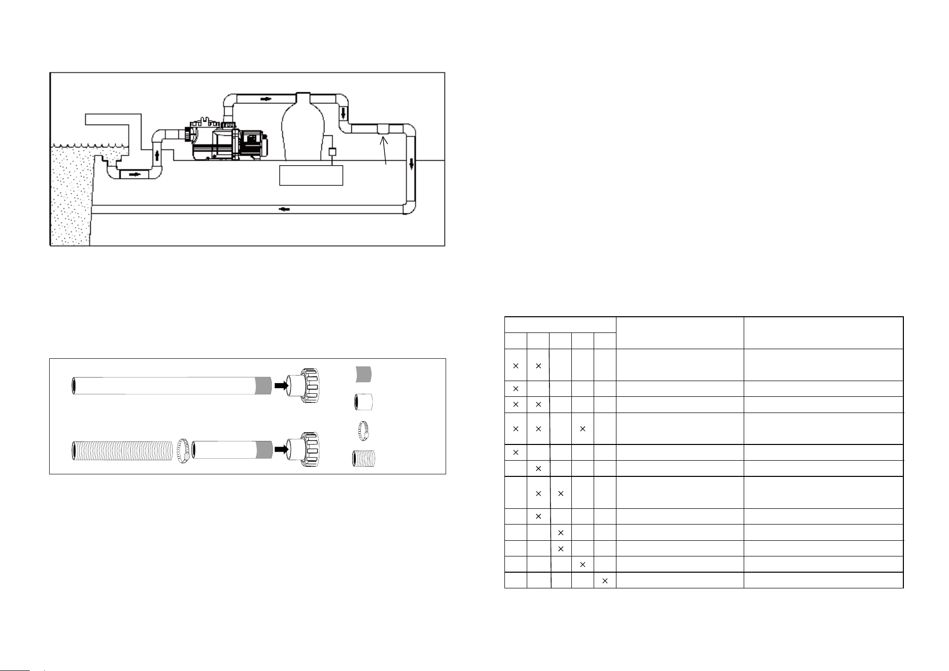
3. Installation of the pipes
4. Electrical Installation
Aquastrong Variable Speed Pool Pumps are easily assembled. For inquiries or technical support, contact
Aquastrong at [email protected].
The pipes can be connected using either 2.5-inch or 2-inch PVC rigid pipes for a direct connection.
Alternatively, a combination of PVC rigid pipes and PVC flexible hoses can be used, secured with hose
clamps for a reliable connection. This flexible approach allows for a more adaptable installation, accom-
modating dierent setup requirements while ensuring a secure and eicient connection for the pump
system.
The user shall inspect and make sure about the eectiveness of protective earthing of the building
installation. In such case, an authorized qualified person shall inspect the building installation.It is
obligatory for the pump electrical power supply to have residual current device (RCD) having a rated
residual operating current not exceeding 30mA.
Up to 100FT: Mandatory use of 12AWG power line.
100 to 200FT: Strongly recommended to use 10AWG power line.
Beyond 200FT: Essential to consult a local professional electrical engineer.
Never work on a pump without first checking that the electrical power is switched o.
Ground
Pool
Pump Located in Zone 2
Filter system
Ground
Located in Zone 3
Power supply
connection
Alternate
output
2.5" or 2" schedule 40 PVC Pipe
2.5" or 2" PVC Pipe Glue Connection+2.5" or 2"PVC Hose with Clamp
Glue Area
PVC Pipe
PVC Hose
Clamp
5
8. Servicing
The Aquastrong Variable Speed Pool Pumps are designed for low maintenance; however, we recom-
mend periodic cleaning of the pre-filter to ensure optimal performance. To perform this task, first shut
o the suction and delivery valves. Then, carefully loosen the black nuts and remove the pre-filter cover.
Withdraw the filtering basket and clean it thoroughly. Inspect the pre-filter cover gasket and replace it if
you notice any damage. If the pump is not in use during winter, it is crucial to drain it (by removing the
drain plug) to prevent damage from freezing. Additionally, clean the pump and store it in a dry, well-ven-
tilated area. In case of malfunction, avoid aempting any repairs yourself and instead contact our
technical support team for assistance.
For your safety, always disconnect the pump from the electrical supply before undertaking any
servicing activities.
9. Problems and Solutions
POSSIBLE FAULTS
1. Pump does not prime
2. Low flow rate
3. Pump makes noise
4. Pump does not start
5. Motor makes noise but does not start
10
1
BLE FAULTS
CAUSES SOLUTIONS
Verity watertightness of connectors
and seals
Clean the cover and verify the seals
Incorrect pump aachment
Clean pump and inspect the filter
Reset the fuses
Call the technical service
Aach pump correctly
Motor blocked
No tension
Refuses in pump
Discharge clogged
Inspect filter and discharge line
Correctly dimension section line
Filter clogged
Clean filter
No water in prefilter
Fill prefilter with water
Incorrect voltage
Verify the vlogate specified on the
nameplate and that of the mains
Set pump at a suitable levelExcessive suction height
Bad watertightness of cover
Air entry
2 3 4 5
Diameter of section line
smaller than required
9
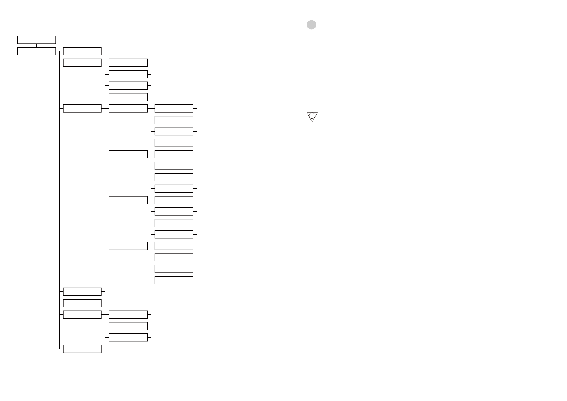
MAIN SCREEN
SETTING Time
Speeds
Speed1
(1200-4000RPM) - Default: 1200 RPM
Speed2
Speed3
Speed4
(1200-4000RPM) - Default: 2000 RPM
(1200-4000RPM) - Default: 3200 RPM
(1200-4000RPM) - Default: 4000 RPM
Schedules
(hr: mm)
Schedule1
Schedule2
Function
Time On
Time O
Speed
(hr: mm)- Default: 08: 30
(hr: mm)- Default: 11: 30
Enabled / Disabled
- Default: Disabled
(1-4)- Default: 1
Schedule3
Schedule4
Function
Time On
Time O
Speed
(hr: mm)- Default: 14: 30
(hr: mm)- Default: 17: 30
Enabled / Disabled
- Default: Disabled
(1-4)- Default: 1
Function
Time On
Time O
Speed
(hr: mm)- Default: 18: 30
(hr: mm)- Default: 21: 30
Enabled / Disabled
- Default: Disabled
(1-4)- Default: 1
Function
Time On
Time O
Speed
(hr: mm)- Default: 22: 30
(hr: mm)- Default: 01: 30
Enabled / Disabled
- Default: Disabled
(1-4)- Default: 1
Language
English / Franais / Deutsch / español / Italiano / 中文 - Default: English
Dry running
Enabled / Disabled- Default: Disabled
Priming Function
Time
Speed
(1- 20 min) - Default: 2 min
(2900 - 4000 RPM) - Default: 2900 RPM
Enabled / Disabled - Default: Enabled
Reset
Restores all seings back to the default values
Programming Flow Chart
The pump should be installed in Zone 2, typically at least 7 feet from the pool. Its power supply connection
must be in Zone 3, generally a minimum1o2eet fromthe pool, as per the International Standard: Electri-
cal Installations of Buildings Part 7 - Requirements for Special Installations or Locations - Swimming Pools
and other Basins (IEC60364-7-702).
Despite having an earthing terminal, the pump must be connected to the equipotential bonding terminal
in the electrical wiring before use. The equipotential bonding terminal is indicated by the following
symbol. For any uncertainties, consult an electrical specialist.
The pump must be powered either via an isolating transformer or through a Residual Current
Device (RCD) with a rated residual operating current not exceeding 30 mA. Electrical installa-
tions should align with national wiring regulations.
In case of supply cord damage, replacement must be done by the manufacturer, an authorized service
agent, or a qualified professional to prevent hazards. The pump is designed for continuous operation. An
all-pole disconnection switch, directly linked to the supply terminals, is required. This switch should
ensure contact separation in all poles for safety. For any inquiries or installation needs, please consult a
professional or an electrical specialist.
Caution:
!
5. Pre-Start Pump Check
1. Verify that the main power supply's voltage and frequency match the specifications on the pump's
identification plate.
2. Ensure that the pump shaft rotates smoothly and freely.
3. Remove the pre-filter cover and fill the pump with water to just below the suction pipe's lower level.
4. Securely reaach the pre-filter cover.
5. If the motor fails to start or no water is being pumped, consult the troubleshooting guide provided
later in this manual.
WARNING: NEVER operate the pump dry or with the water inlet blocked.
6. Starting the Pump
Once the pump is filled with water, open all suction and delivery valves, then initiate the motor. Allowtime
for self-priming. Proper priming is achieved when the water level reaches just belowthe transparent
cover.
6
The LCD Display backlight turns o after 60 seconds of inactivity, but can be reactivated by pressing any
buon.
The Aquastrong Variable Speed Pool Pump is an advanced version of the standard pool pump, featuring
an added controller for enhanced system management.
Aention: Users should not remove or alter the display face sticker. If the sticker is damaged or improp-
erly aixed, the pump must be sent to an authorized service agent or the manufacturer for repair.
The controller is equipped with a power limit function, which is a top priority. If the pump's power
exceeds the set threshold, the controller will adjust by reducing the pump's speed. This may result in the
speed displayed being occasionally lower than the set speed, ensuring eicient and safe operation.
7. Function:
User’s guide
Functions of the controller is shown below:
>Time: Built in the time clock.
> Speed Display: Expressed in RPM. Shows the operating speed.
>Preset pump speed: Four optional preset running speeds available.
> Display: Time, four preset running speeds, power, schedule seings and fault codes.
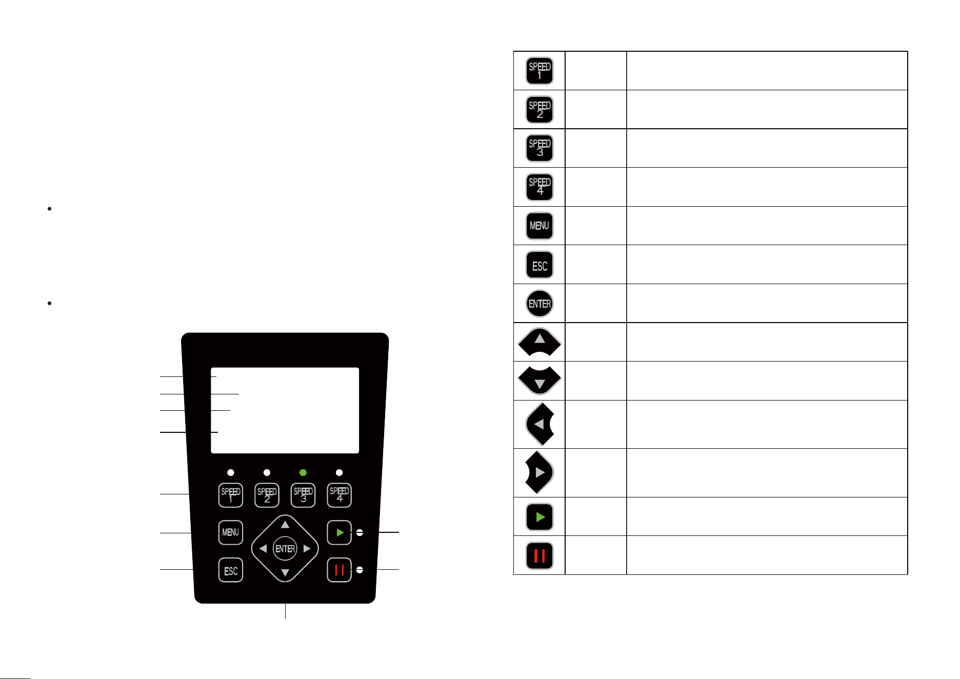
Overview
Display interface
09:00 08:30 On
11:30 OT1
3200RPM
1150W
Speed3
Time
Current Speed
Scheduled Program
Current Input Power
Start
Stop
Change Values
Program Menu
ESC
Speed 1 ( 1200RPM)
Speed 2 (2000RPM)
Speed 3 (3200RPM)
Speed 4 (4000RPM)
Speed 1
Decrease
Speed 2
Speed 3
Speed 4
Menu
ESC
Enter
Increase
Left
Right
Start
Stop
Press this buon to adjust (increase) the seing
Press this buon to adjust (decrease) the seing
Move the cursor keys (select unit, Loop display)
Move the cursor keys (select unit, Loop display)
Back/Cancel
Description of Controls
Press the buon to access the parameter adjustment menu
when the motor is o.
Press this buon to start the motor, LED next to the buon
switches on
Press this buon to stop the motor, LED next to the buon
turn red. Drive fault reset key
Enter sub-menu, adjust speed seings or save them.
Press the buon to choose a motor speed; the LED next to it
lights up to show selection.
Press the buon to choose a motor speed; the LED next to it
lights up to show selection.
Press the buon to choose a motor speed; the LED next to it
lights up to show selection.
Press the buon to choose a motor speed; the LED next to it
lights up to show selection.
7
8