
0
Mobile Network Camera
User Manual

Mobile Network Camera • User Manual
I
Legal Information
© 2023 Hangzhou Hikvision Digital Technology Co., Ltd. All rights reserved.
About this Manual
The Manual includes instructions for using and managing the Product. Pictures, charts, images and all other information
hereinafter are for description and explanation only. The information contained in the Manual is subject to change,
without notice, due to firmware updates or other reasons. Please find the latest version of this Manual at the Hikvision
website (https://www.hikvision.com/).
Please use this Manual with the guidance and assistance of professionals trained in supporting the Product.
Trademarks
and other Hikvision’s trademarks and logos are the properties of Hikvision in various jurisdictions.
Other trademarks and logos mentioned are the properties of their respective owners.
Disclaimer
TO THE MAXIMUM EXTENT PERMITTED BY APPLICABLE LAW, THIS MANUAL AND THE PRODUCT DESCRIBED, WITH ITS
HARDWARE, SOFTWARE AND FIRMWARE, ARE PROVIDED “AS IS” AND “WITH ALL FAULTS AND ERRORS”. HIKVISION
MAKES NO WARRANTIES, EXPRESS OR IMPLIED, INCLUDING WITHOUT LIMITATION, MERCHANTABILITY, SATISFACTORY
QUALITY, OR FITNESS FOR A PARTICULAR PURPOSE. THE USE OF THE PRODUCT BY YOU IS AT YOUR OWN RISK. IN NO
EVENT WILL HIKVISION BE LIABLE TO YOU FOR ANY SPECIAL, CONSEQUENTIAL, INCIDENTAL, OR INDIRECT DAMAGES,
INCLUDING, AMONG OTHERS, DAMAGES FOR LOSS OF BUSINESS PROFITS, BUSINESS INTERRUPTION, OR LOSS OF DATA,
CORRUPTION OF SYSTEMS, OR LOSS OF DOCUMENTATION, WHETHER BASED ON BREACH OF CONTRACT, TORT
(INCLUDING NEGLIGENCE), PRODUCT LIABILITY, OR OTHERWISE, IN CONNECTION WITH THE USE OF THE PRODUCT,
EVEN IF HIKVISION HAS BEEN ADVISED OF THE POSSIBILITY OF SUCH DAMAGES OR LOSS.
YOU ACKNOWLEDGE THAT THE NATURE OF THE INTERNET PROVIDES FOR INHERENT SECURITY RISKS, AND HIKVISION
SHALL NOT TAKE ANY RESPONSIBILITIES FOR ABNORMAL OPERATION, PRIVACY LEAKAGE OR OTHER DAMAGES
RESULTING FROM CYBER-ATTACK, HACKER ATTACK, VIRUS INFECTION, OR OTHER INTERNET SECURITY RISKS; HOWEVER,
HIKVISION WILL PROVIDE TIMELY TECHNICAL SUPPORT IF REQUIRED.
YOU AGREE TO USE THIS PRODUCT IN COMPLIANCE WITH ALL APPLICABLE LAWS, AND YOU ARE SOLELY RESPONSIBLE
FOR ENSURING THAT YOUR USE CONFORMS TO THE APPLICABLE LAW. ESPECIALLY, YOU ARE RESPONSIBLE, FOR USING
THIS PRODUCT IN A MANNER THAT DOES NOT INFRINGE ON THE RIGHTS OF THIRD PARTIES, INCLUDING WITHOUT
LIMITATION, RIGHTS OF PUBLICITY, INTELLECTUAL PROPERTY RIGHTS, OR DATA PROTECTION AND OTHER PRIVACY
RIGHTS. YOU SHALL NOT USE THIS PRODUCT FOR ANY PROHIBITED END-USES, INCLUDING THE DEVELOPMENT OR
PRODUCTION OF WEAPONS OF MASS DESTRUCTION, THE DEVELOPMENT OR PRODUCTION OF CHEMICAL OR
BIOLOGICAL WEAPONS, ANY ACTIVITIES IN THE CONTEXT RELATED TO ANY NUCLEAR EXPLOSIVE OR UNSAFE NUCLEAR
FUEL-CYCLE, OR IN SUPPORT OF HUMAN RIGHTS ABUSES.
IN THE EVENT OF ANY CONFLICTS BETWEEN THIS MANUAL AND THE APPLICABLE LAW, THE LATTER PREVAILS.

Mobile Network Camera • User Manual
II
Regulatory Information
FCC Information
Please take attention that changes or modification not expressly approved by the party responsible
for compliance could void the user’s authority to operate the equipment.
FCC Compliance
This equipment has been tested and found to comply with the limits for a Class A digital device,
pursuant to part 15 of the FCC Rules. These limits are designed to provide reasonable protection
against harmful interference when the equipment is operated in a commercial environment. This
equipment generates, uses, and can radiate radio frequency energy and, if not installed and used in
accordance with the instruction manual, may cause harmful interference to radio communications.
Operation of this equipment in a residential area is likely to cause harmful interference in which
case the user will be required to correct the interference at his own expense.
FCC Conditions
This device complies with part 15 of the FCC Rules. Operation is subject to the following two
conditions:
1. This device may not cause harmful interference.
2. This device must accept any interference received, including interference that may cause
undesired operation.
EU Conformity Statement
This product and - if applicable - the supplied accessories too are marked with "CE" and
comply therefore with the applicable harmonized European standards listed under the RE
Directive 2014/53/EU, EMC Directive 2014/30/EU, the LVD Directive 2014/35/EU, the RoHS
Directive 2011/65/EU.
2012/19/EU (WEEE directive): Products marked with this symbol cannot be disposed of as
unsorted municipal waste in the European Union. For proper recycling, return this product
to your local supplier upon the purchase of equivalent new equipment, or dispose of it at
designated collection points. For more information see: www.recyclethis.info
2006/66/EC (battery directive): This product contains a battery that cannot be disposed
of as unsorted municipal waste in the European Union. See the product documentation
for specific battery information. The battery is marked with this symbol, which may include
lettering to indicate cadmium (Cd), lead (Pb), or mercury (Hg). For proper recycling, return the
battery to your supplier or to a designated collection point. For more information see:
www.recyclethis.info
Industry Canada ICES-003 Compliance
This device meets the CAN ICES-3 (A)/NMB-3(A) standards requirements.
Mobile Network Camera • User Manual
III
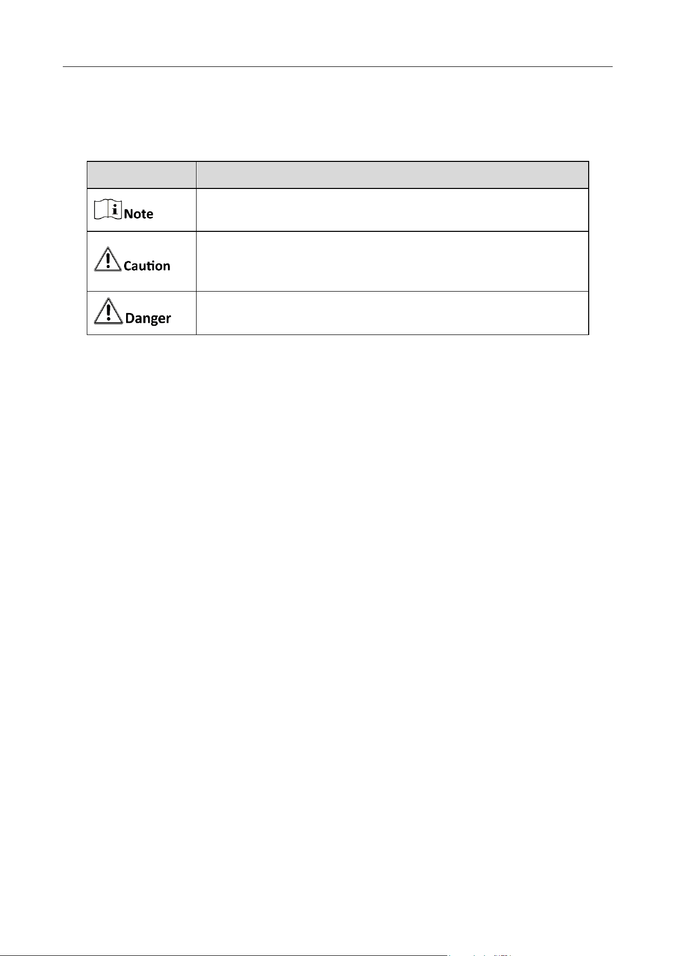
Symbol Conventions
The symbols that may be found in this document are defined as follows.
Safety Instructions
Proper configuration of all passwords and other security settings is the responsibility of the
installer and/or end-user.
In the use of the product, you must be in strict compliance with the electrical safety
regulations of the nation and region. Please refer to technical specifications for detailed
information.
Input voltage should meet limited power source or PS2 requirements according to the
IEC60950-1 or IEC 62368-1 standard. Please refer to technical specifications for detailed
information.
Do not connect several devices to one power adapter as adapter overload may cause over-
heating or a fire hazard.
Please make sure that the plug is firmly connected to the power socket.
If smoke, odor or noise rise from the device, turn off the power at once and unplug the power
cable, and then please contact the service center.
Symbol
Description
Provides additional information to emphasize or supplement
important points of the main text.
Indicates a potentially hazardous situation, which if not avoided,
could result in equipment damage, data loss, performance
degradation, or unexpected results.
Indicates a hazard with a high level of risk, which if not avoided, will
result in death or serious injury.

Mobile Network Camera • User Manual
IV
TABLE OF CONTENTS
Chapter 1 Product Introduction ...................................................................................................... 1
Product Features............................................................................................................................................ 1
Function Features .......................................................................................................................................... 1
Chapter 2 Operation Instructions ................................................................................................... 3
Setting the Network Camera over the LAN ..................................................................................................... 3
2.1.1 Wiring over the LAN ............................................................................................................................ 3
Activating the Camera .................................................................................................................................... 4
2.2.1 Activation via SADP Software ............................................................................................................... 4
2.2.2 Activation via Web Browser ................................................................................................................. 6
2.2.3 (Optional) Setting Security Question .................................................................................................... 7
Login and Logout............................................................................................................................................ 8
2.3.1 Login ................................................................................................................................................... 8
2.3.2 Logout ................................................................................................................................................. 9
Main Interface ............................................................................................................................................... 9
Chapter 3 Basic Functions............................................................................................................. 11
Local Parameters ..........................................................................................................................................11
3.1.1 Live View Parameters .........................................................................................................................11
3.1.2 Record File Setting ..............................................................................................................................12
3.1.3 Picture and Clip Setting.......................................................................................................................12
Live View ......................................................................................................................................................12
3.2.1 Live View Page....................................................................................................................................12
3.2.2 Starting Live View ...............................................................................................................................13
3.2.3 Record and Capture Pictures Manually ...............................................................................................14
Playback .......................................................................................................................................................14
Picture ..........................................................................................................................................................17
Chapter 4 System Configuration ................................................................................................... 18
Configure System Settings .............................................................................................................................18
4.1.1 Basic Information ...............................................................................................................................18
4.1.2 Time Settings ......................................................................................................................................19
4.1.3 DST ....................................................................................................................................................20
Maintenance.................................................................................................................................................21
4.2.1 Upgrade & Maintenance.....................................................................................................................21
4.2.2 Log .....................................................................................................................................................22
Security.........................................................................................................................................................24
4.3.1 Authentication ...................................................................................................................................24
4.3.2 Security Service ..................................................................................................................................25
User Management ........................................................................................................................................26
4.4.1 User Management ..............................................................................................................................26
4.4.2 Security Question ...............................................................................................................................28
4.4.3 Online Users .......................................................................................................................................30
Chapter 5 Network Settings ......................................................................................................... 31
Basic Settings ................................................................................................................................................31
5.1.1 TCP/IP ................................................................................................................................................31
5.1.2 Port ....................................................................................................................................................32
5.1.3 Multicast ............................................................................................................................................33

Mobile Network Camera • User Manual
V
Advanced Settings.........................................................................................................................................33
5.2.1 HTTPS .................................................................................................................................................33
5.2.2 Integration Protocol ...........................................................................................................................34
5.2.3 Network Service .................................................................................................................................35
Chapter 6 Video and Audio Settings ............................................................................................. 36
Video Settings ...............................................................................................................................................36
Audio ............................................................................................................................................................39
Chapter 7 OSD Settings................................................................................................................. 41
Chapter 8 Storage Settings ........................................................................................................... 43
Record Schedule ...........................................................................................................................................43
Capture Schedule and Capture Parameters ...................................................................................................44
Storage Management....................................................................................................................................45
Advanced Settings.........................................................................................................................................46
Chapter 9 Driving Status Monitoring Settings .............................................................................. 47
Driving Status Monitoring .............................................................................................................................47
Advanced Parameters ...................................................................................................................................48
Chapter 10 Access to the Network Camera .................................................................................. 49
10.1.1 Via Static IP Connection ....................................................................................................................49
10.1.2 Via Dynamic IP Connection ...............................................................................................................50
Chapter 11 Appendix: SADP Software Introduction ..................................................................... 51

Mobile Network Camera • User Manual
1
Chapter 1 Product Introduction
Product Features
The main function of this DSM (Driving Status Monitoring) mobile network camera
(hence force the “camera”) is for monitoring the driving status inside the vehicle.
Based on the deep learning algorithm, the camera detects abnormality and send
alarms, to alter the driver of possible dangers and improve driving safety.
The camera can be deployed in various settings, including bus, train, metro and special
vehicles such as construction vehicles.
Function Features
The camera supports numerous DSM detection, voice alarm and capture, and the
export of pictures and videos with TF card to facilitate the investigation of incidents.
DSM detection
Distraction Prompt Detection
When the driver is detected distracted, the camera will send alarms.
Fatigue Driving (Closing Eyes) Detection
When the driver is detected yawning or with eyes closed, the camera will send alarms.
Fatigue Driving (Yawn) Detection
When the driver is detected fatigue driving, the camera will send alarms.
Phone Call Detection
When the driver is detected making phone calls while driving, the camera will send
alarms.
Smoking Detection
When the driver is detected smoking, the camera will send alarms.
Seatbelt Unbuckled Detection
When the driver is detected with seatbelt unbuckled, the camera will send alarms.
Driver Exception Detection
When the driver is detected as absent from the driving seat, the camera will send
alarms.
Tampering Detection
When the camera is detected tampered, the camera will send alarms.
IR Interrupted Sunglasses Detection

Mobile Network Camera • User Manual
2
When the driver is detected putting up sunglasses that blocks infrared, the camera will
send alarms.
System function
Video recording and capturing pictures
The camera supports instant capture and video recording during preview, and after
installing memory card, you can also configure video recording and capture plan to
realize scheduled video recording and capture.
User Management
You can manage many different users through the administrator "admin" user, and
configure different permissions for each user.
Network function
The camera supports TCP/IP, MULTICAST and other network communication protocols;
it also supports open interconnection protocols such as ONVIF.
Mobile Network Camera • User Manual
3
Chapter 2 Operation Instructions
You shall acknowledge that the use of the product with Internet access might be
under network security risks. For avoidance of any network attacks and
information leakage, please strengthen your own protection. If the product does
not work properly, please contact with your dealer or the nearest service center.
To ensure the network security of the network camera, we recommend you to
have the network camera assessed and maintained termly. You can contact us if
you need such service.
Before you start:
If you want to set the network camera via a LAN (Local Area Network), please
refer to Section 2.1 Setting the Network Camera over the LAN.
If you want to set the network camera via a WAN (Wide Area Network), please
refer to Section 2.2 Setting the Network Camera over the WAN.
Setting the Network Camera over the LAN
Purpose:
To view and configure the camera via a LAN, you need to connect the network camera
in the same subnet with your computer, and install the SADP or iVMS-4200 software
to search and change the IP of the network camera.
For the detailed introduction of SADP, please refer to Appendix 1.
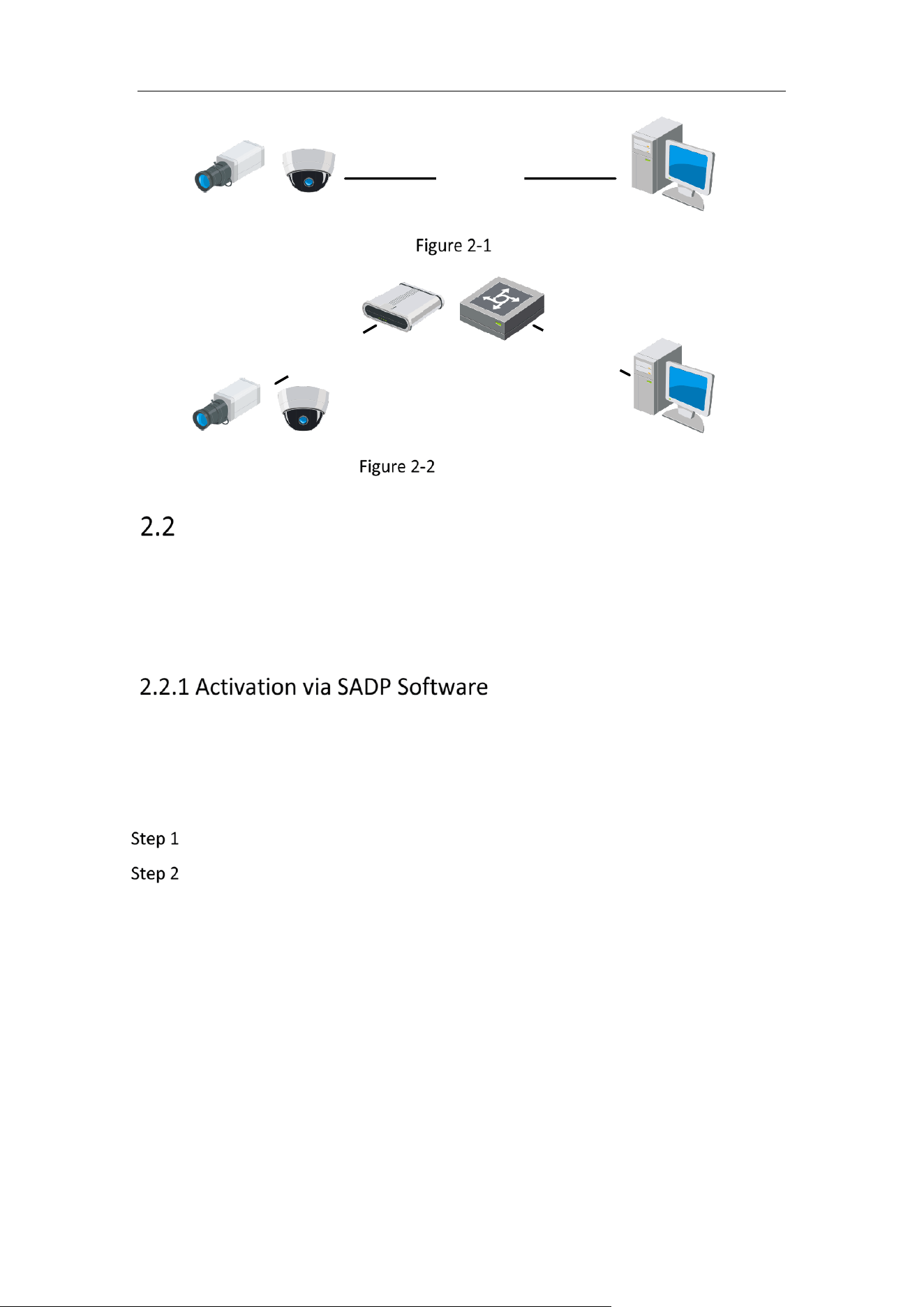
The following figures show the two ways of cable connection of a network camera and
a computer:
Purpose:
To test the network camera, you can directly connect the network camera to the
computer with a network cable as shown in Figure 2-1.
Refer to the Figure 2-2 to set network camera over the LAN via a switch or a
router.
Mobile Network Camera • User Manual
4
半球
Network Cable
or
Network Camera
Computer
Connecting Directly
网络交换机
半球
Network Cable
Network Cable
or
or
Network Camera Computer
Connecting via a Switch or a Router
Activating the Camera
You are required to activate the camera first by setting a strong password for it before
you can use the camera.
Activation via Web Browser, Activation via SADP, and Activation via Client Software are
all supported.
SADP software is used for detecting the online device, activating the camera, and
resetting the password.
Get the SADP software from the official website, and install the SADP according to the
prompts. Follow the steps to activate the camera.
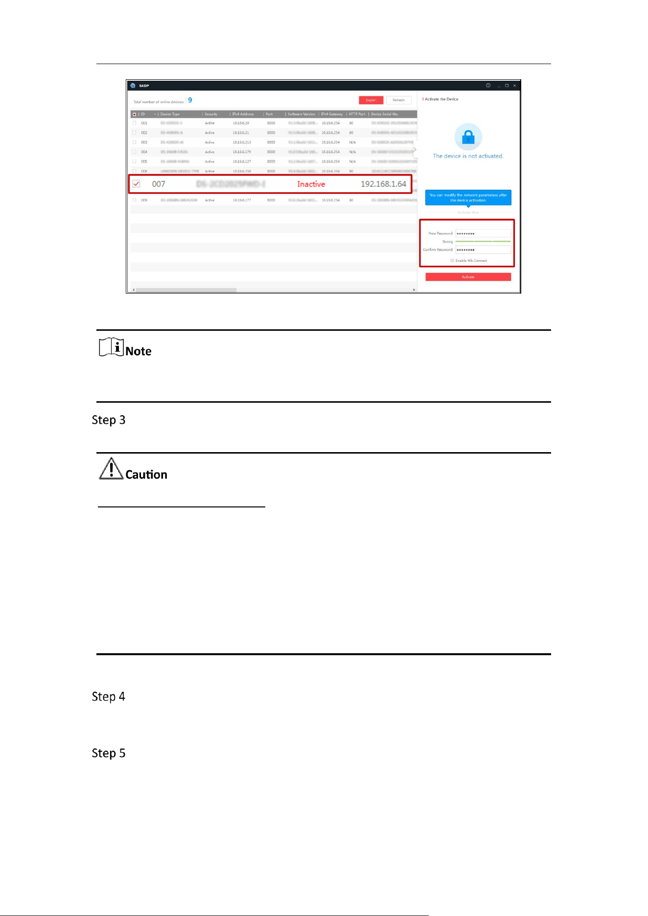
Run the SADP software to search the online devices.
Check the device status from the device list, and select the inactive device.
Mobile Network Camera • User Manual
5
SADP Interface
The SADP software supports activating the camera in batch. Refer to the user
manual of SADP software for details.
Create and input the password in the password field, and confirm the password.
A password with user name in it is not allowed.
STRONG PASSWORD RECOMMENDED
We highly recommend you create a strong password of your own choosing (using
a minimum of 8 characters, including at least three of the following categories:
upper case letters, lower case letters, numbers, and special characters) in order to
increase the security of your product. And we recommend you reset your
password regularly, especially in the high security system, resetting the password
monthly or weekly can better protect your product.
Proper configuration of all passwords and other security settings is the
responsibility of the installer and/or end-user.
You can enable the Hik-Connect service for the device during activation.
Click Activate to start activation. You can check whether the activation is
completed on the popup window. If activation failed, please make sure that the
password meets the requirement and try again.
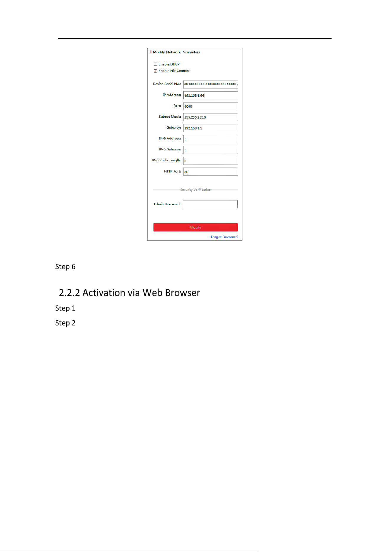
Change the device IP address to the same subnet with your computer by either
modifying the IP address manually or checking the checkbox of Enable DHCP.
Select inactive device.
Input and confirm
password.
Mobile Network Camera • User Manual
6
Modify the IP Address
Input the admin password and click Modify to activate your IP address
modification.
Power on the camera, and connect the camera to the network.
Input the IP address into the address bar of the web browser, and click Enter to
enter the activation interface.
Mobile Network Camera • User Manual
7
The default IP address of the camera is 192.168.1.64.
The computer and the camera should belong to the same subnet.
For the camera enables the DHCP by default, you need to use the SADP software
to search the IP address.
Activation via Web Browser
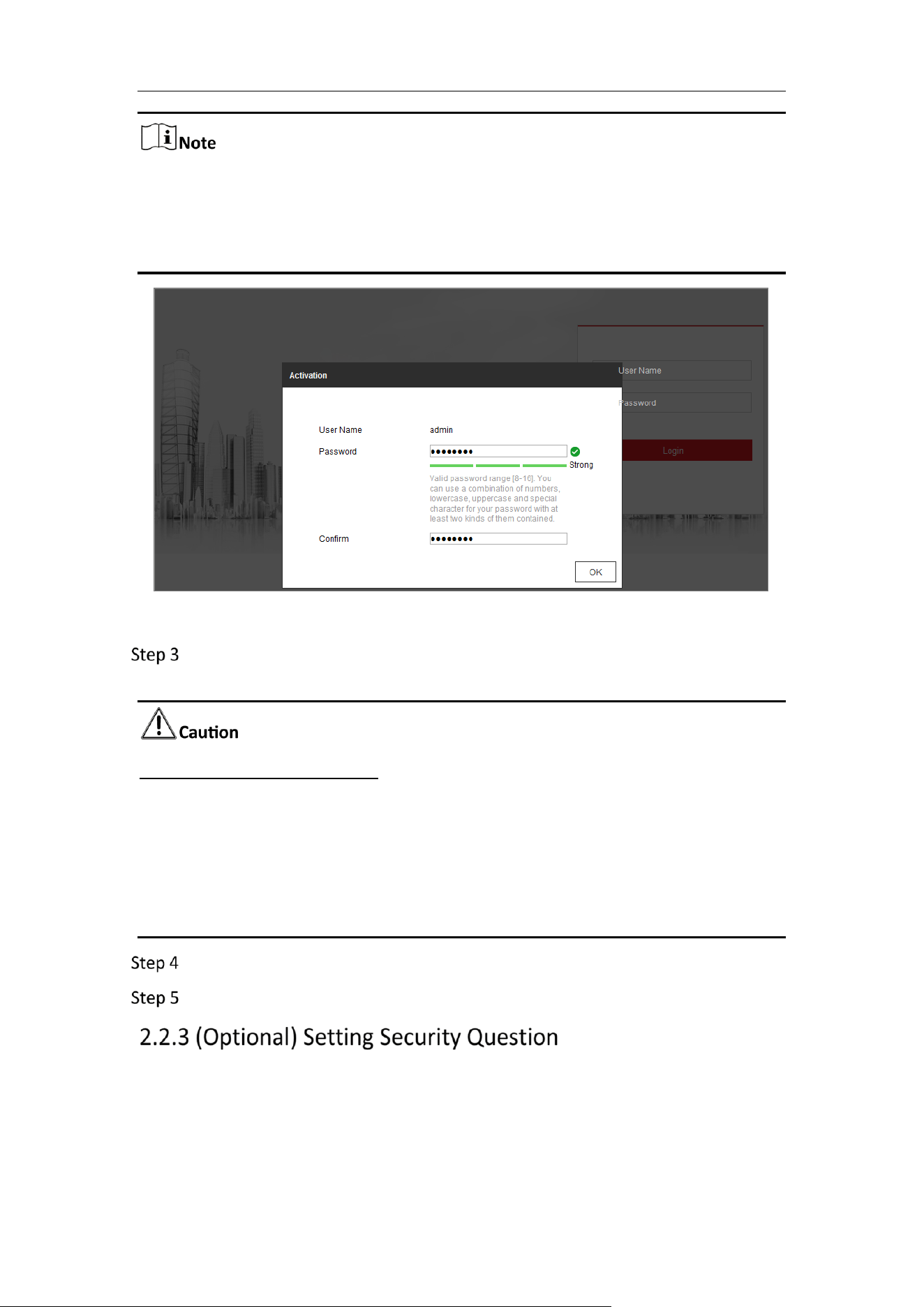
Create and input a password into the password field. A password with user name
in it is not allowed.
STRONG PASSWORD RECOMMENDED
We highly recommend you create a strong password of your own choosing (using
a minimum of 8 characters, including at least three of the following categories:
upper case letters, lower case letters, numbers, and special characters) in order to
increase the security of your product. And we recommend you reset your
password regularly, especially in the high security system, resetting the password
monthly or weekly can better protect your product.
Confirm the password.
Click OK to save the password and enter the live view interface.
Security question is used to reset the admin password when admin user forgets the
password.
Admin user can follow the pop-up window to complete security question settings
during camera activation. Or, admin user can go to User Management interface to
configure the function.
Mobile Network Camera • User Manual
8
Login and Logout
For certain camera models, HTTPS is enabled by default and the camera creates an
unsigned certificate automatically. When you access to the camera the first time, the
web browser prompts a notification about the certificate issue.
To cancel the notification, install a signed-certificate to the camera.
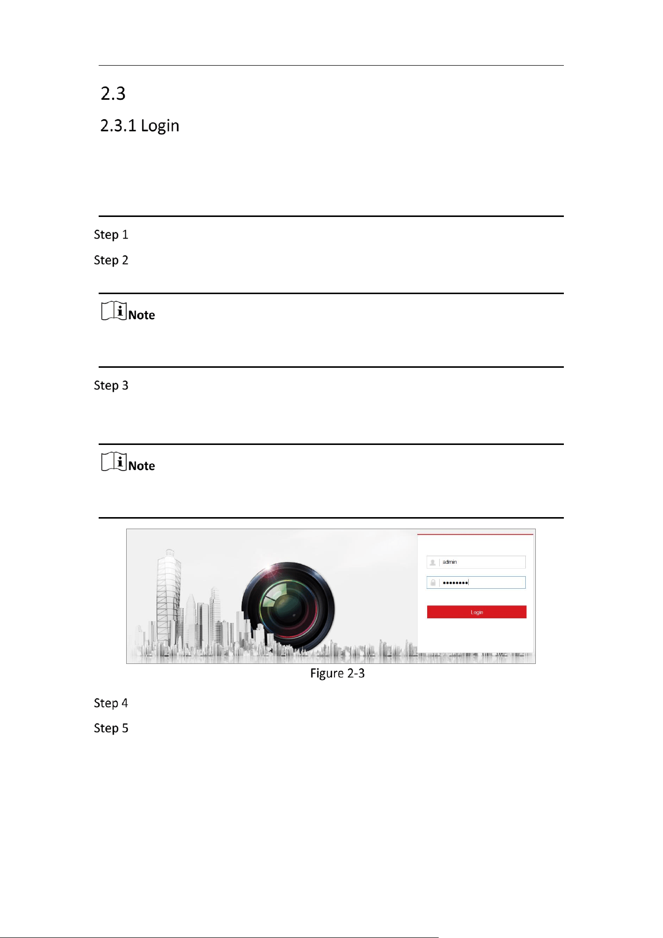
Open the web browser.
In the browser address bar, input the IP address of the network camera, and
press the Enter key to enter the login interface.
The default IP address is 192.168.1.64. You are recommended to change the IP
address to the same subnet with your computer.
Input the user name and password.
The admin user should configure the device accounts and user/operator permissions
properly. Delete the unnecessary accounts and user/operator permissions.
The IP address gets locked if the admin user performs 7 failed password attempts (5
attempts for the user/operator).
Login Interface
Click Login.
(Optional) Install the plug-in before viewing the live video and operating the
camera. Follow the installation prompts to install the plug-in.
Mobile Network Camera • User Manual
9
Install Plugins
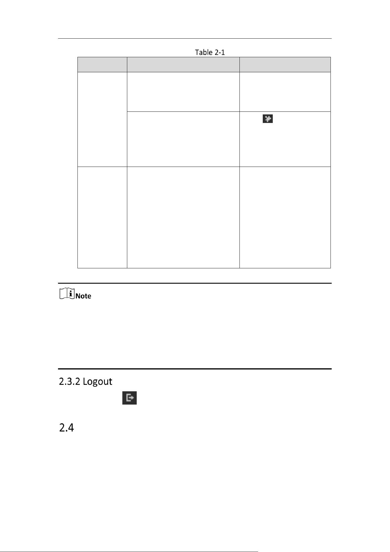
OS
Browser Version
Plugin
Windows
IE 8 and upper
Google Chrome 57 and lower
Mozilla Firefox 52 and lower
Install the plugin
according to instructions.
Google Chrome 57 and upper
Mozilla Firefox 52 and upper
Click in the preview
page to download and
install the plugin for high
quality view and device
functions.
Mac OS
Google Chrome 57 and upper
Mozilla Firefox 52 and upper
Mac Safari 16 and upper
To preview, enter
Configuration > Network >
Advanced Setting >
Network Service, and
enbale WebSocket. Some
functions will be limited
after enbling this function,
such as video play. The
actual equipment shall
prevail.
For camera that supports plug-in free live view, if you are using Google Chrome 57
and its above version or Mozilla Firefox 52 and its above version, plug-in installation
is not required. But Picture and Playback functions are hidden. To use mentioned
function via web browser, change to their lower version, or change to Internet
Explorer 8.0 and above version.
Login without plug-in only supports configuration, not preview and playback.
To logout, click the icon.
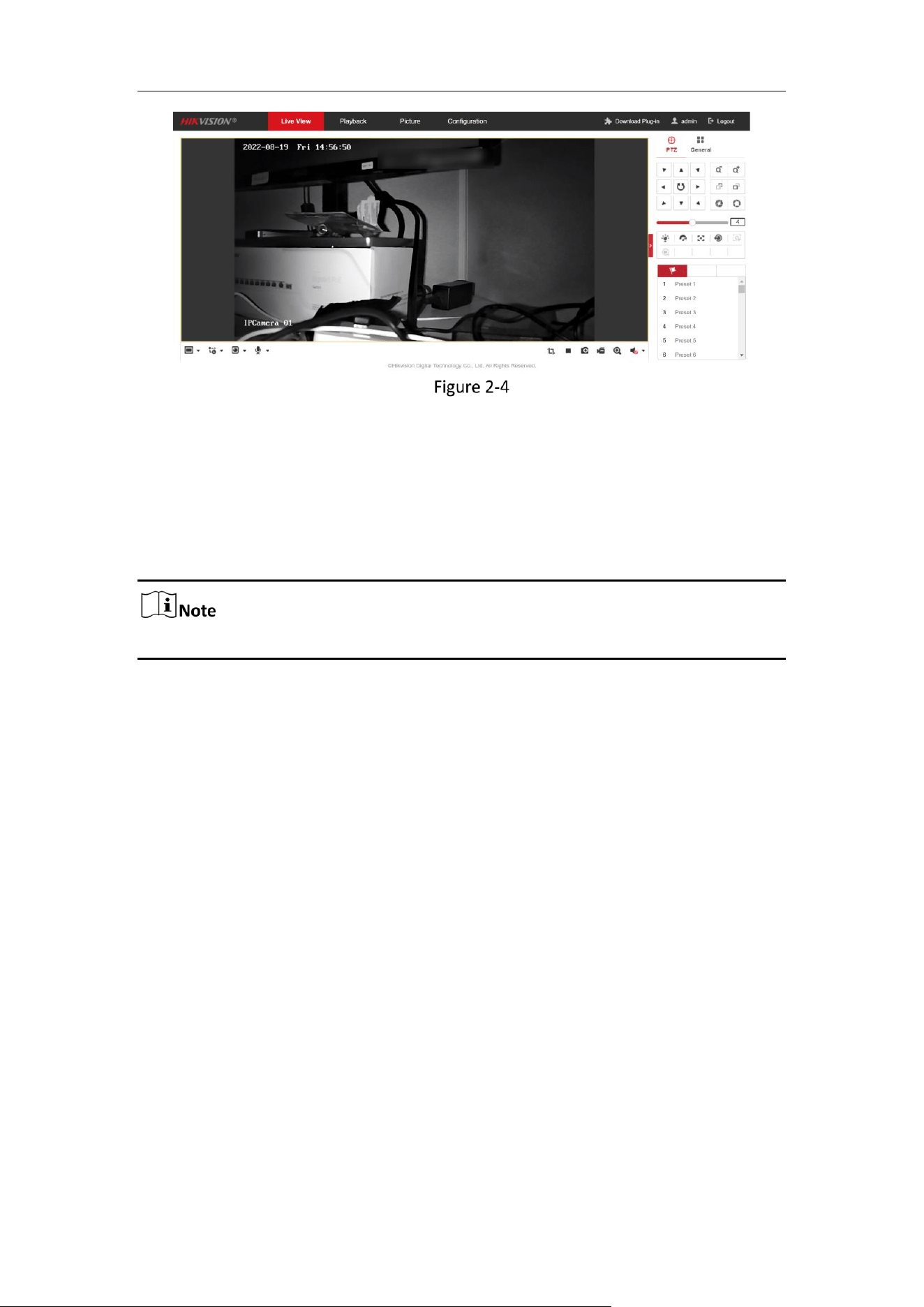
Main Interface
The main interface is shown as follows.
Mobile Network Camera • User Manual
10
Main Interface
Live View: to view the camera and set parameters.
Playback: to play recordings according to their type and time.
Picture: to search, view and download the pictures stored in the SD Card of the
network camera.
Configuration: to set the system and function parameters.
The interface may vary according to the model of the camera.
Mobile Network Camera • User Manual
11
Chapter 3 Basic Functions
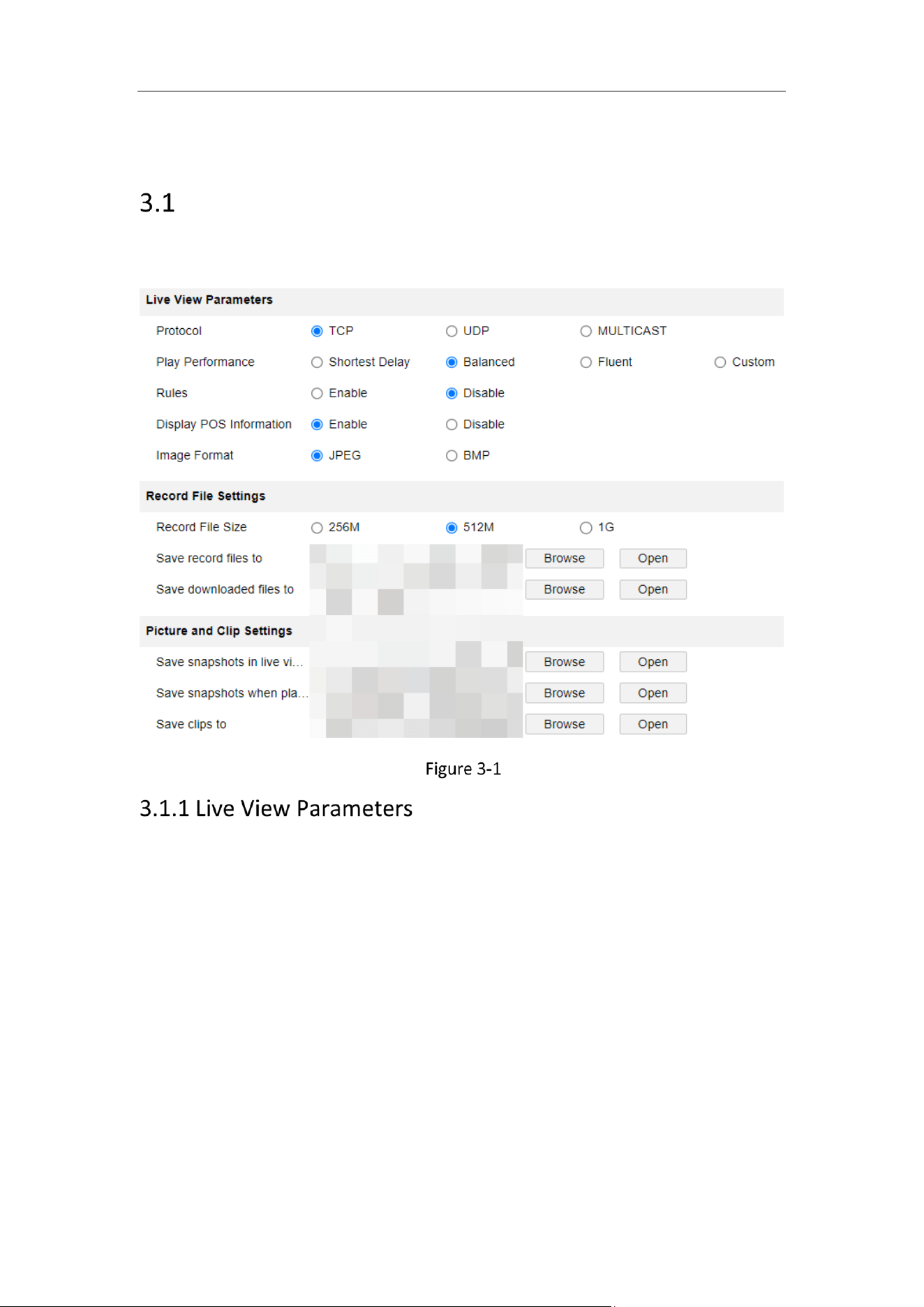
Local Parameters
Go to Configuration > Local to configure local configurations. Live View Parameters,
Record File Settings, Picture and Clip Settings can be configured.
Local Parameters
Protocols
TCP, UDP and MULTICAST protocols are supported.
− The default protocol is TCP
− UDP is suitable for the situation that the requirement of video fluency is not high
and the network environment is unstable.
− MULTICAST is suitable for multicast addresses with many customers and need to
be configured before selection.
Playback performance:
You can choose the shortest delay, Balanced, Fluent and Custom, and the default is
Custom.
Minimum delay: Real-time is good, but it may affect the fluency of video.
Balance: Give consideration to the real-time and fluency of video playback.
Mobile Network Camera • User Manual
12
Good fluency: In the same network situation, it takes up less network resources,
and the video is smoother than other modes.
Custom: the frame rate can be set according to the network conditions.
Information: You can choose to enable or disable it. When enabled, information
boxes will appear on the live screen, including the dynamic analysis box of
motion detection and the face target box.
POS information overlay: it can be enabled or disabled. When enabled, when a
target triggers a rule, the live screen will display the attribute information of the
target.
Picture and Clip Settings: set the format of captured pictures, with optional JPEG
and BMP.
Record File Size: it can be set to 256 M, 512 M and 1 G, indicating the size of a
single video file stored locally.
Save record files to: the path where video files are stored locally. You can choose
Browse to change the path, and click Open Folder to open the folder under the
archive path.
Save downloaded files to: the path where the video files saved during playback
are stored locally. You can choose Browse to change the path, and click Open
Folder to open the folder under the archive path.
Save snapshots in live view to: the path where the captured pictures are stored
locally during preview. You can choose Browse to change the path, and click
Open Folder to open the folder under the archive path.
Save snapshots when playback to: the path where captured pictures are stored
locally during playback. You can choose Browse to change the path, and click
Open Folder to open the folder under the archive path.
Save clips to: the path where the cut video files are stored locally during
playback. You can choose Browse to change the path, and click Open Folder to
open the folder under the archive path.
Live View
Purpose:
The live view page allows you to view the real-time video, capture images, realize PTZ
control, set/call presets and configure video parameters.
Log in the network camera to enter the live view page, or you can click Live View on
the menu bar of the main page to enter the live view page.
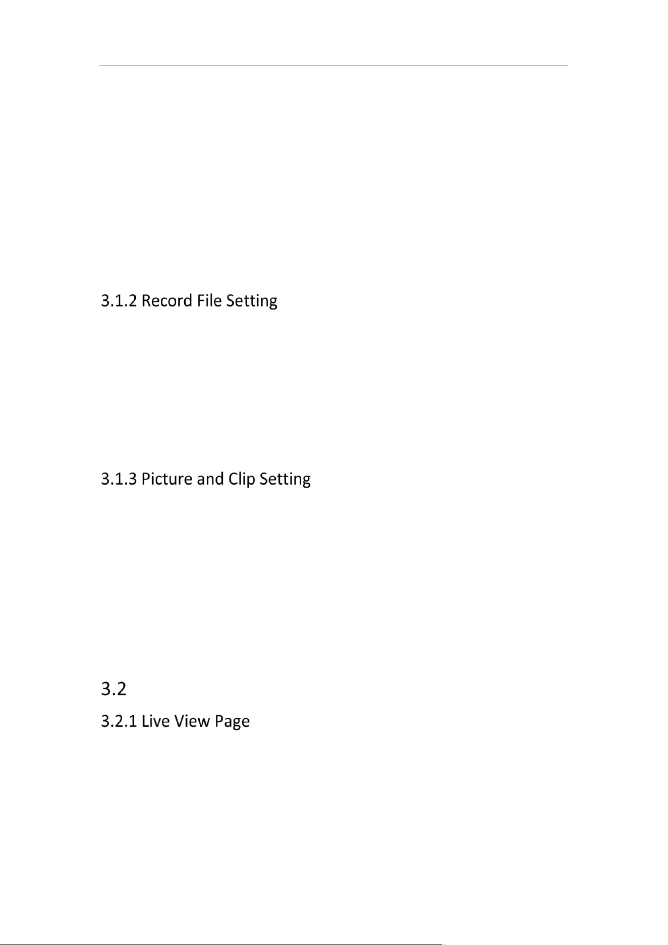
Descriptions of the live view page:
Mobile Network Camera • User Manual
13
Live View Page
Menu Bar
Click each tab to enter Live View, Playback, Picture, Application, and Configuration
page respectively.
Live View Window
Display the live video.
Toolbar
Toolbar allows you to adjust the live view window size, the stream type, and the plug-
ins. It also allows you to process the operations on the live view page, e.g., start/stop
live view, capture, record, audio on/off, two-way audio, start/stop digital zoom, etc.
For IE (Internet Explorer) users, plug-ins as webcomponents and quick time are
selectable. And for Non-IE users, webcomponents, quick time, VLC or MJPEG are
selectable if they are supported by the web browser.
For camera that supports plug-in free live view, when Google Chrome 45 and its
above version or Mozilla Firefox 52 and its above version are used, plug-in
installation is not required. But Picture and Playback functions are hidden. To use
mentioned function via web browser, change to their lower versions, or change to
Internet Explorer 8.0 and its above version.
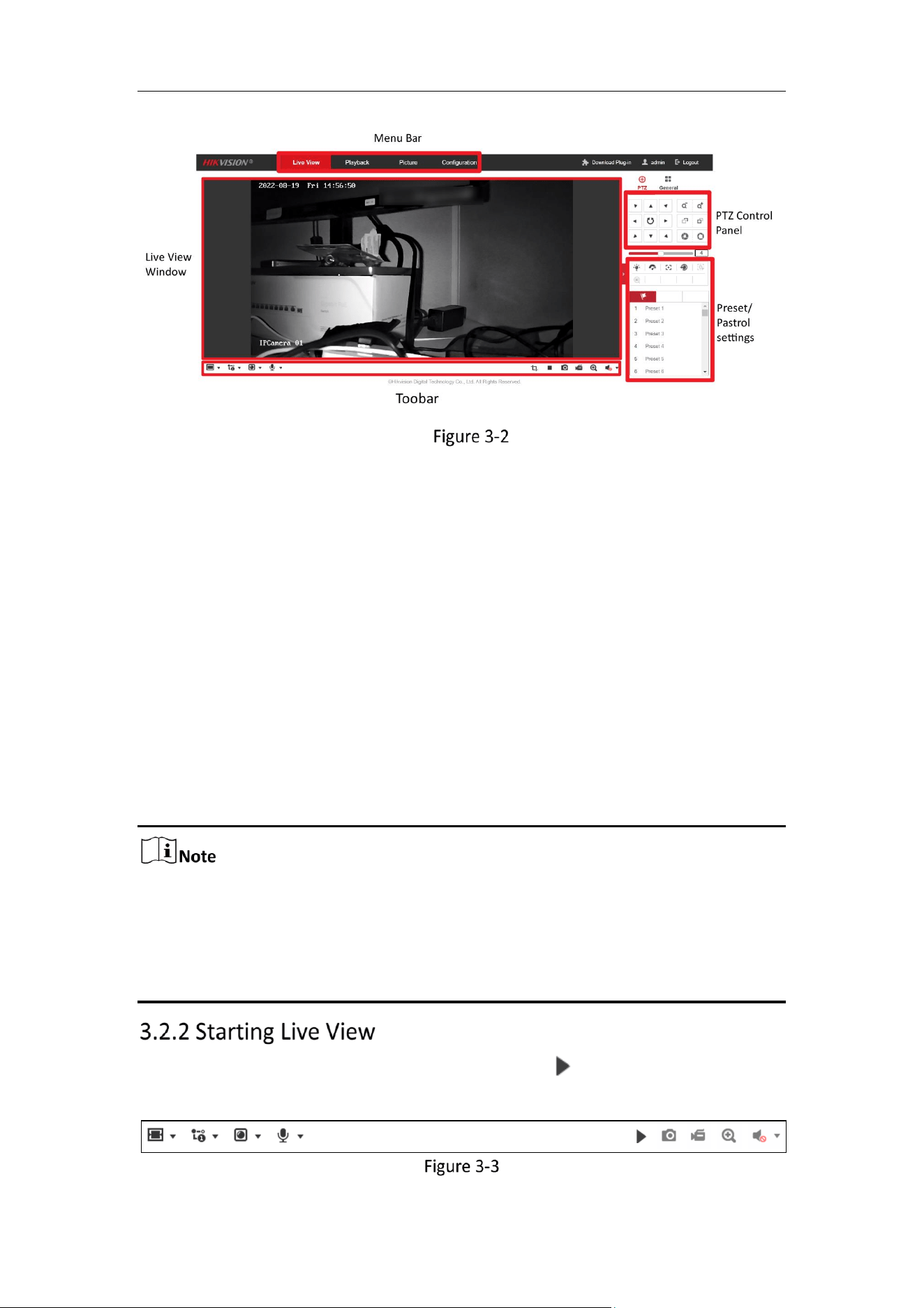
In the live view window as shown in Figure 4-2, click on the toolbar to start the
live view of the camera.
Live View Toolbar
Mobile Network Camera • User Manual
14
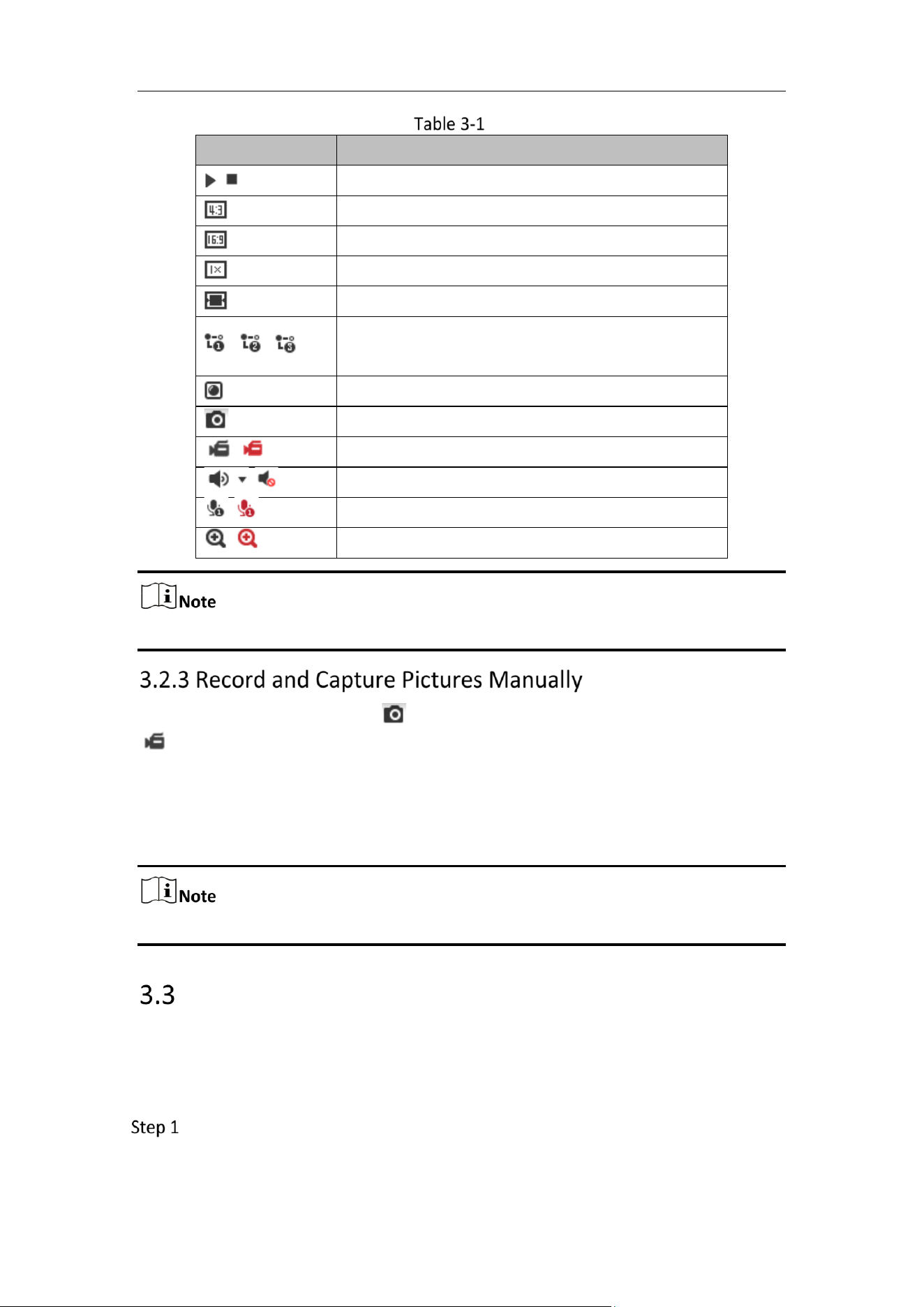
Descriptions of the Toolbar
Icon
Description
/
Start/Stop live view.
The window size is 4:3.
The window size is 16:9.
The original widow size.
Self-adaptive window size.
, , , etc.
Live view with the different video streams.
Supported video streams vary according to camera models.
Click to select the third-party plug-in.
Manually capture the picture.
/
Manually start/stop recording.
/
Audio on and adjust volume /Mute.
/
Turn on/off microphone.
/
Start/stop digital zoom function.
The icons vary according to the different camera models.
In the live view interface, click on the toolbar to capture the live pictures; click
to record the live view. The saving paths of the captured pictures and clips can be
set on the Configuration > Local page. To configure remote scheduled recording, please
refer to 8.1 Record Schedule.
The captured image will be saved as a JPEG file or BMP file in your computer.
Playback
Purpose:
This section explains how to view the remotely recorded video files stored in the
network disks or SD cards.
Click Playback on the menu bar to enter playback interface.
Mobile Network Camera • User Manual
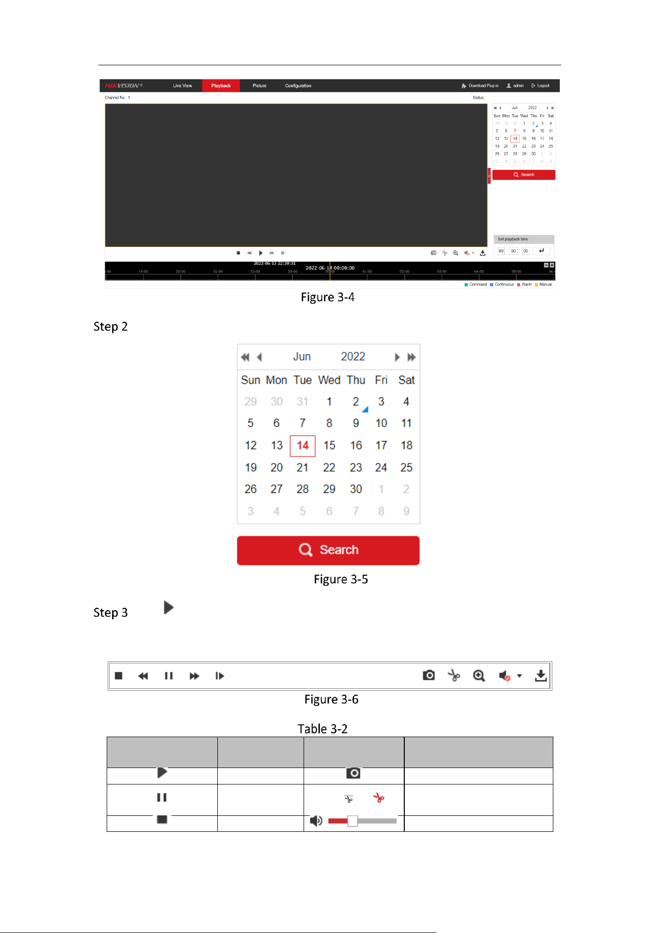
15
Playback Interface
Select the date and click Search.
Search Video
Click to play the video files found on this date.
The toolbar on the bottom of Playback interface can be used to control playing
process.
Playback Toolbar
Description of the buttons
Button
Operation
Button
Operation
Play
Capture a picture
Pause
/
Start/Stop clipping video
files
Stop
Audio on and adjust volume
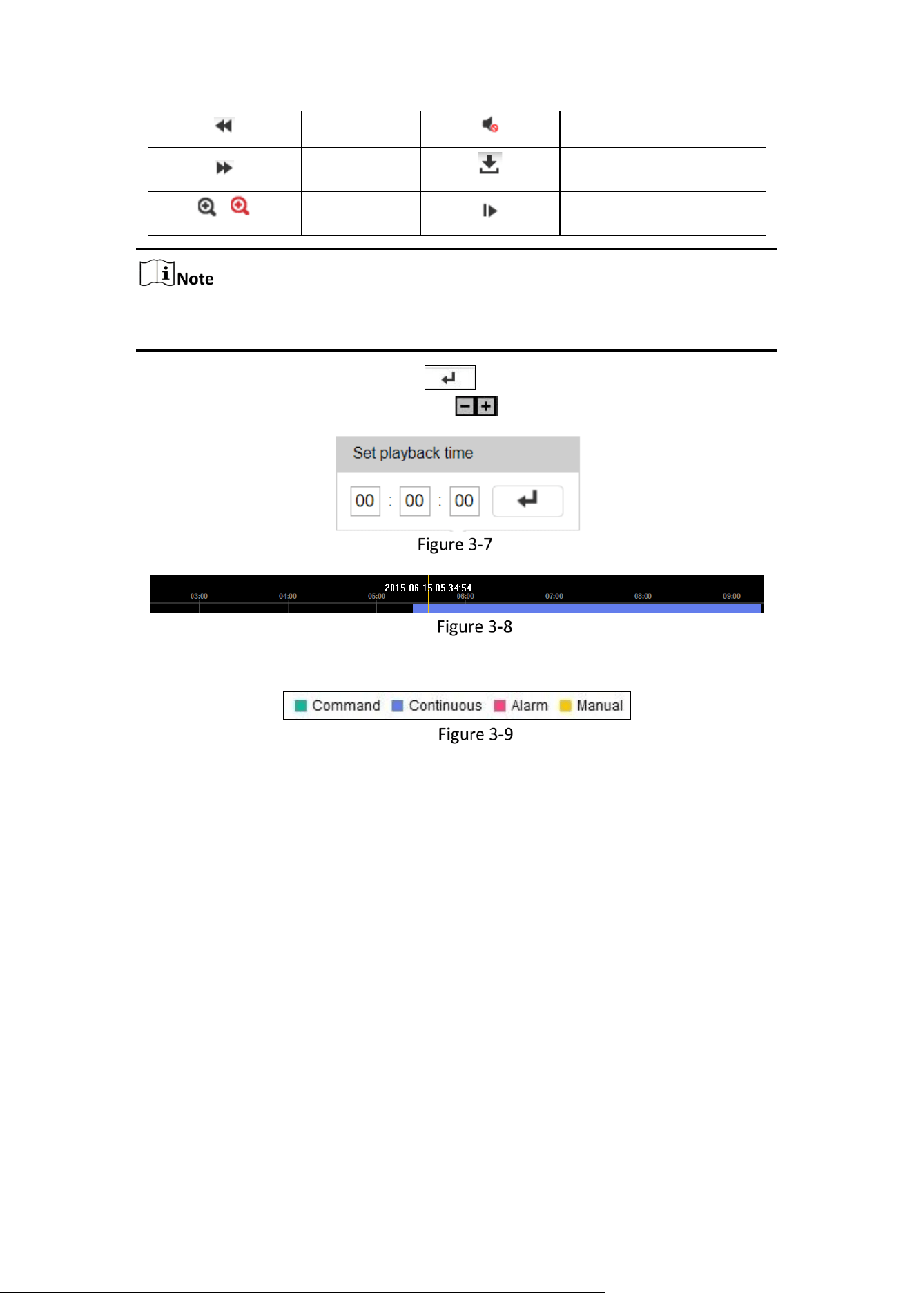
Mobile Network Camera • User Manual
16
Speed down
Mute
Speed up
Download
/
Enable/Disable
digital zoom
Playback by frame
You can choose the file paths locally for downloaded playback video files and
pictures in Local Configuration interface.
You can also input the time and click to locate the playback point in the Set
playback time field. You can also click to zoom out/in the progress bar.
Set Playback Time
Progress Bar
The different colors of the video on the progress bar stand for the different video types.
Video Types
Mobile Network Camera • User Manual
17
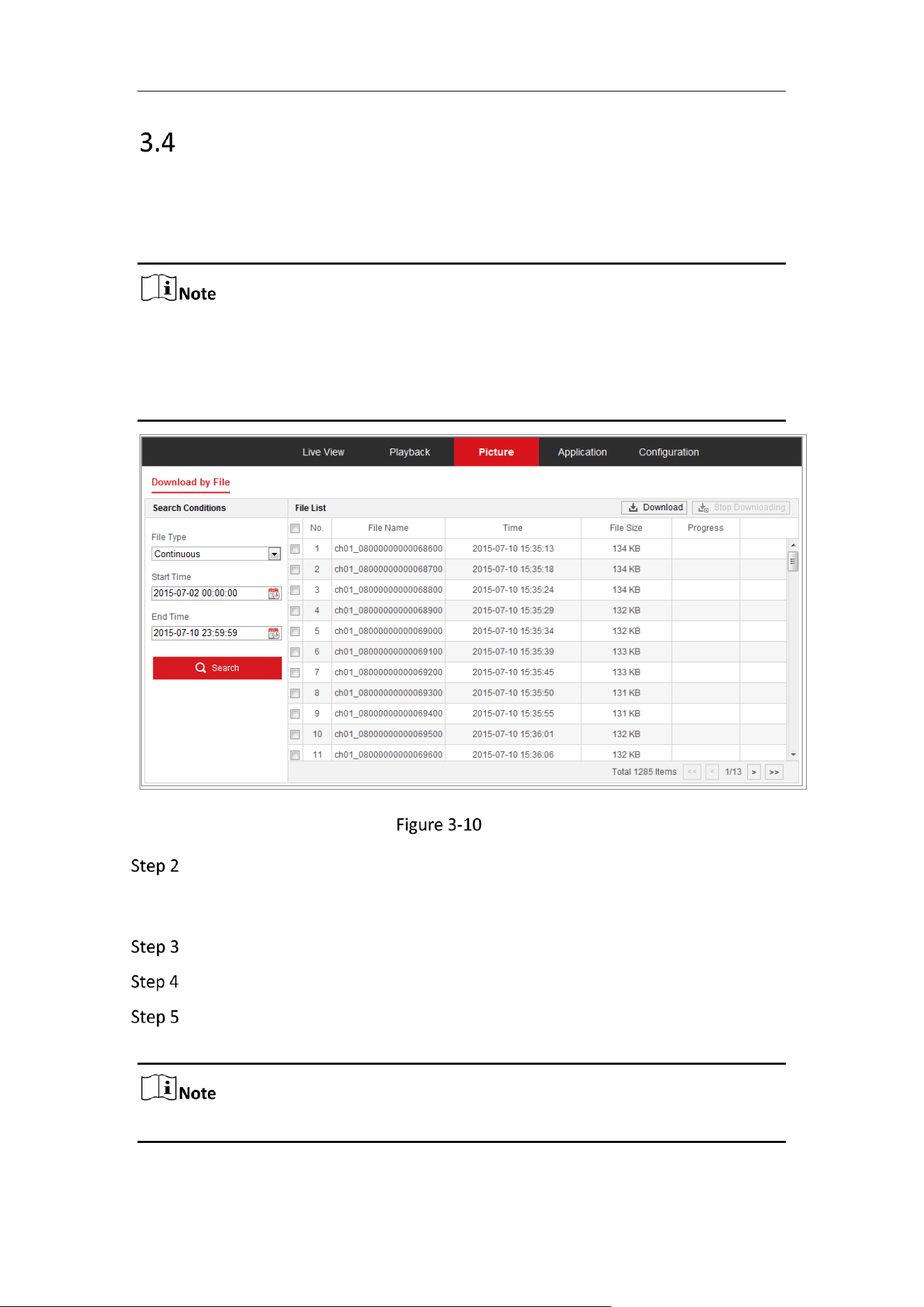
Picture
Purpose:
Click Picture to enter the picture searching interface. You can search, view, and
download the pictures stored in the local storage or network storage.
Make sure HDD, NAS or memory card are properly configured before you process
the picture search.
Make sure the capture schedule is configured. Go to Configuration > Storage >
Schedule Settings > Capture to set the capture schedule.
Picture Search Interface
Select the file type from the dropdown list. Continuous, Motion, Alarm, Motion
| Alarm, Motion & Alarm, Line Crossing, Intrusion Detection, and Scene Change
Detection are selectable.
Select the start time and end time.
Click Search to search the matched pictures.
Check the checkbox of the pictures and then click Download to download the
selected pictures.
Up to 4000 pictures can be displayed at one time.
Mobile Network Camera • User Manual
18
Chapter 4 System Configuration
Configure System Settings
Purpose:
Follow the instructions below to configure the system settings, include System Settings,
Maintenance, Security, and User Management, etc.
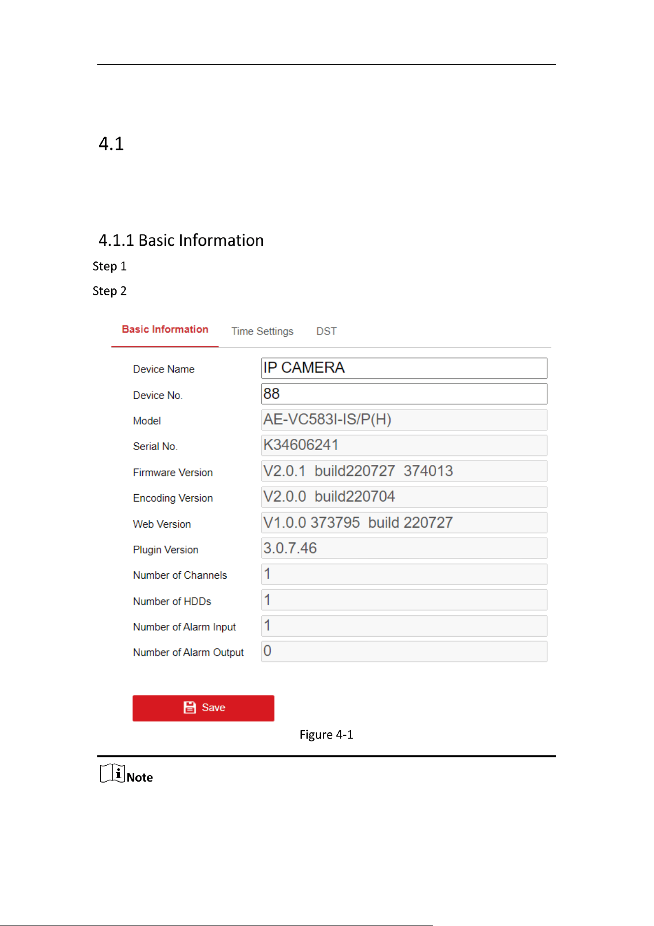
Go to Configuration > System > System Settings > Basic Information.
Edit the Device Name and Device No.
Basic Information
Other information of the network camera, such as Model, Serial No., Firmware
Version, Encoding Version, Number of Channels, Number of HDDs, Number of
Alarm Input and Number of Alarm Output are displayed. The information cannot
Mobile Network Camera • User Manual
19
be changed in this menu. These options are the reference for maintenance or
modification in future.
Purpose:
You can follow the instructions in this section to configure the time synchronization
and DST settings.
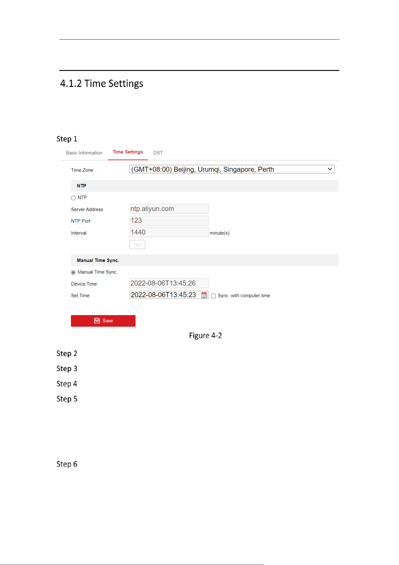
Go to Configuration > System> System Settings > Time Settings.
Time Settings
Select the Time Zone of your location from the drop-down menu.
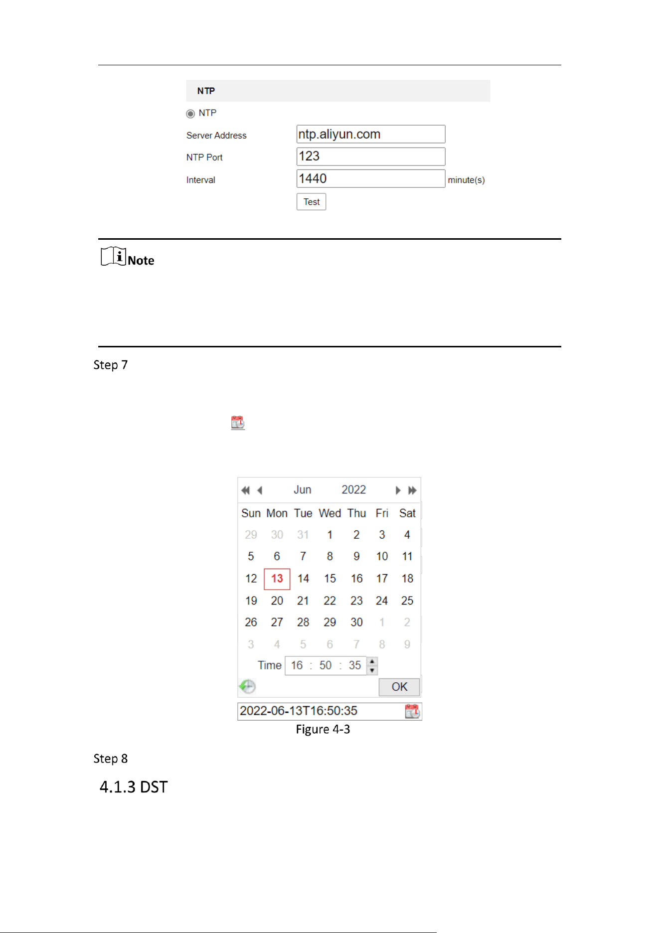
Configure the NTP settings.
Click to enable the NTP function.
Configure the following settings:
Server Address: IP address of NTP server.
NTP Port: Port of NTP server.
Interval: The time interval between the two synchronizing actions with NTP
server.
(Optional) You can click the Test button to test the time synchronization function
via NTP server.
Mobile Network Camera • User Manual
20
Time Sync by NTP Server
If the camera is connected to a public network, you should use a NTP server that
has a time synchronization function, such as the server at the National Time
Center (IP Address: 210.72.145.44). If the camera is set in a customized network,
NTP software can be used to establish a NTP server for time synchronization.
Configure the manual time synchronization.
1) Check the Manual Time Sync. item to enable the manual time
synchronization function.
2) Click the icon to select the date, time from the pop-up calendar.
3) (Optional) You can check Sync. with computer time item to synchronize the
time of the device with that of the local PC.
Time Sync Manually
Click Save to save the settings.
Mobile Network Camera • User Manual
21
Purpose:
Daylight Saving Time (DST) is a way of making better use of the natural daylight by
setting your clock forward one hour during the summer months, and back again in the
fall.
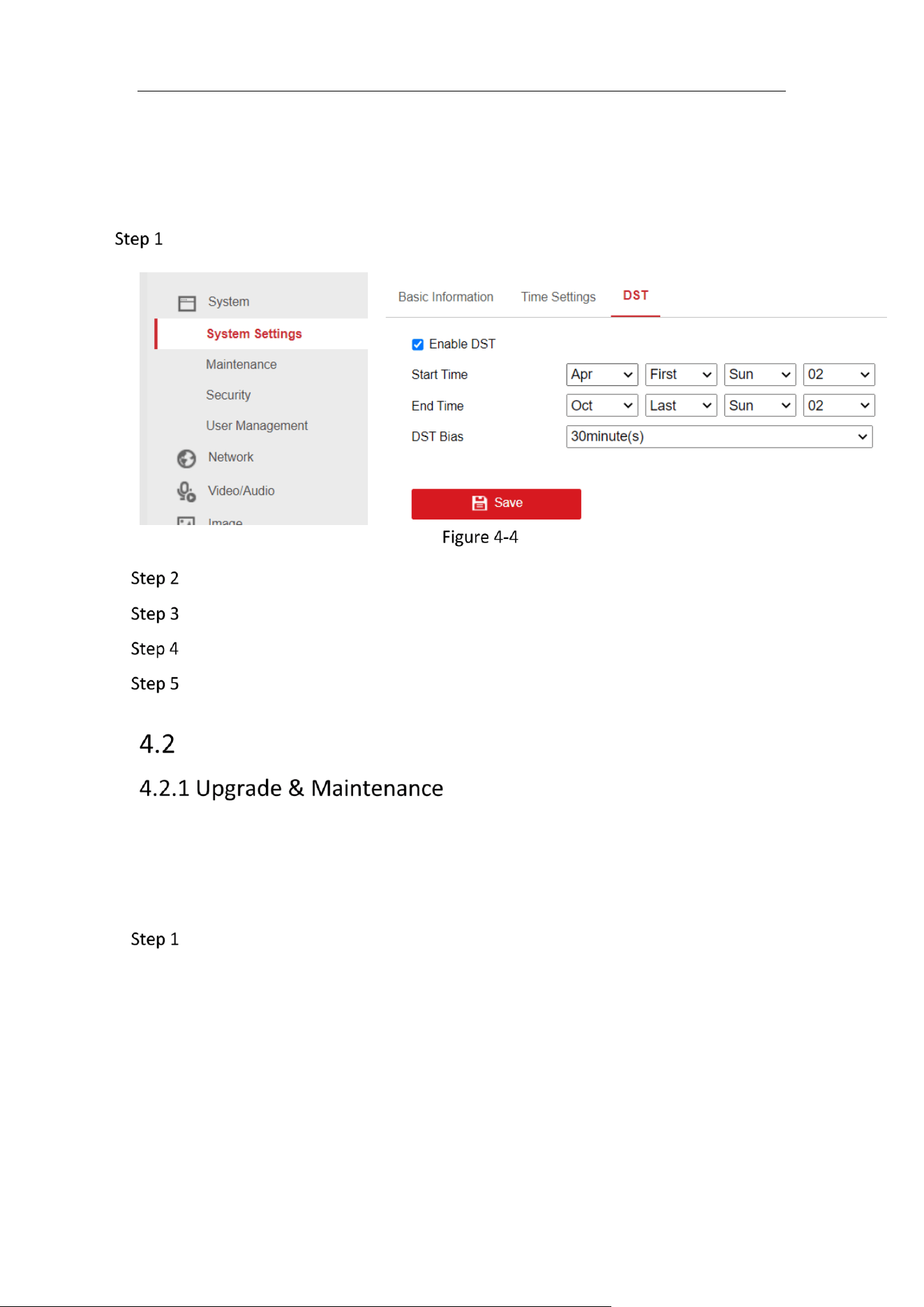
Go to Configuration > System > System Settings > DST.
DST Settings
Check Enable DST.
Select the start time and the end time.
Select the DST Bias.
Click Save to activate the settings.
Maintenance
Purpose:
The upgrade & maintenance interface allows you to process the operations, including
reboot, partly restore, restore to default, export/import the configuration files, and
upgrade the device.
Go to Configuration > System > Maintenance > Upgrade & Maintenance.
Reboot: Restart the device.
Restore: Reset all the parameters, except the IP parameters and user
information, to the default settings.
Default: Restore all the parameters to the factory default.

Mobile Network Camera • User Manual
22
After restoring the default settings, the IP address is also restored to the default
IP address, please be careful for this action.
For camera that supports Wi-Fi, wireless dial, or wlan function, Restore action
does not restore the related settings of mentioned functions to default.
Information Export
Device Parameters: click to export the current configuration file of the camera.
This operation requires admin password to proceed.
For the exported file, you also have to create an encryption password. The encryption
password is required when you import the file to other cameras.
Diagnose Information: click to download log and system information.
Import Config. File
Configuration file is used for the batch configuration of the cameras.
Click Browse to select the saved configuration file.
Click Import and input the encryption password that you set during exporting.
The camera needs rebooting after importing configuration file.
Upgrade: Upgrade the device to a certain version.
Select firmware or firmware directory to locate the upgrade file.
Firmware: Locate the exact path of the upgrade file.
Firmware Directory: Only the directory the upgrade file belongs to is required.
Click Browse to select the local upgrade file and then click Upgrade to start
remote upgrade.
The upgrading process will take 1 to 10 minutes. Please don't disconnect power
of the camera during the process, and the camera reboots automatically after
upgrade.
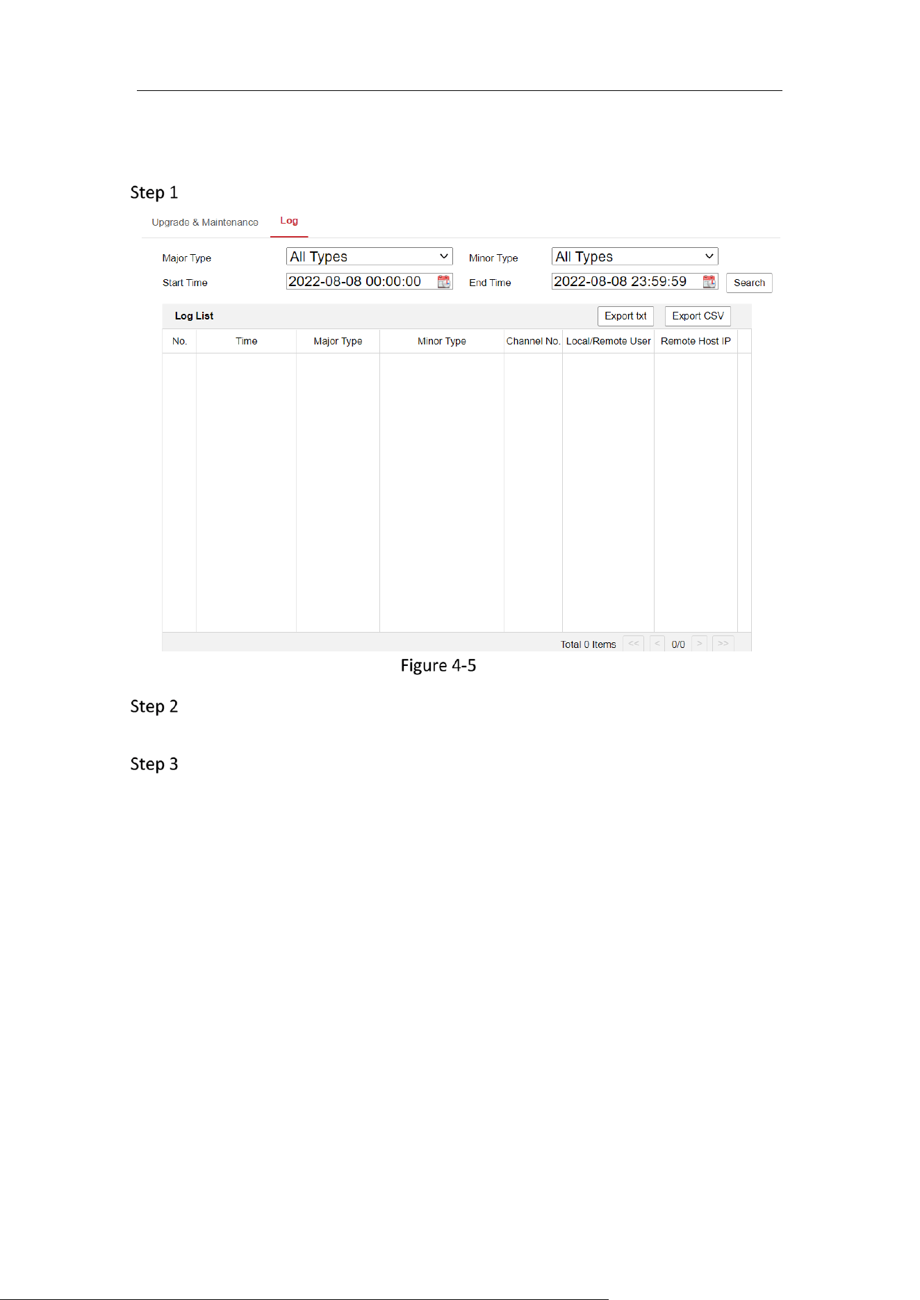
Purpose:
The operation, alarm, exception and information of the camera can be stored in log
files. You can also export the log files on your demand.
Mobile Network Camera • User Manual
23
Before you start:
Please configure network storage for the camera or insert a SD card in the camera.
Go to Configuration > System > Maintenance > Log.
Log Searching Interface
Set the log search conditions to specify the search, including the Major Type,
Minor Type, Start Time and End Time.
Click Search to search log files. The matched log files will be displayed on the log
list interface.
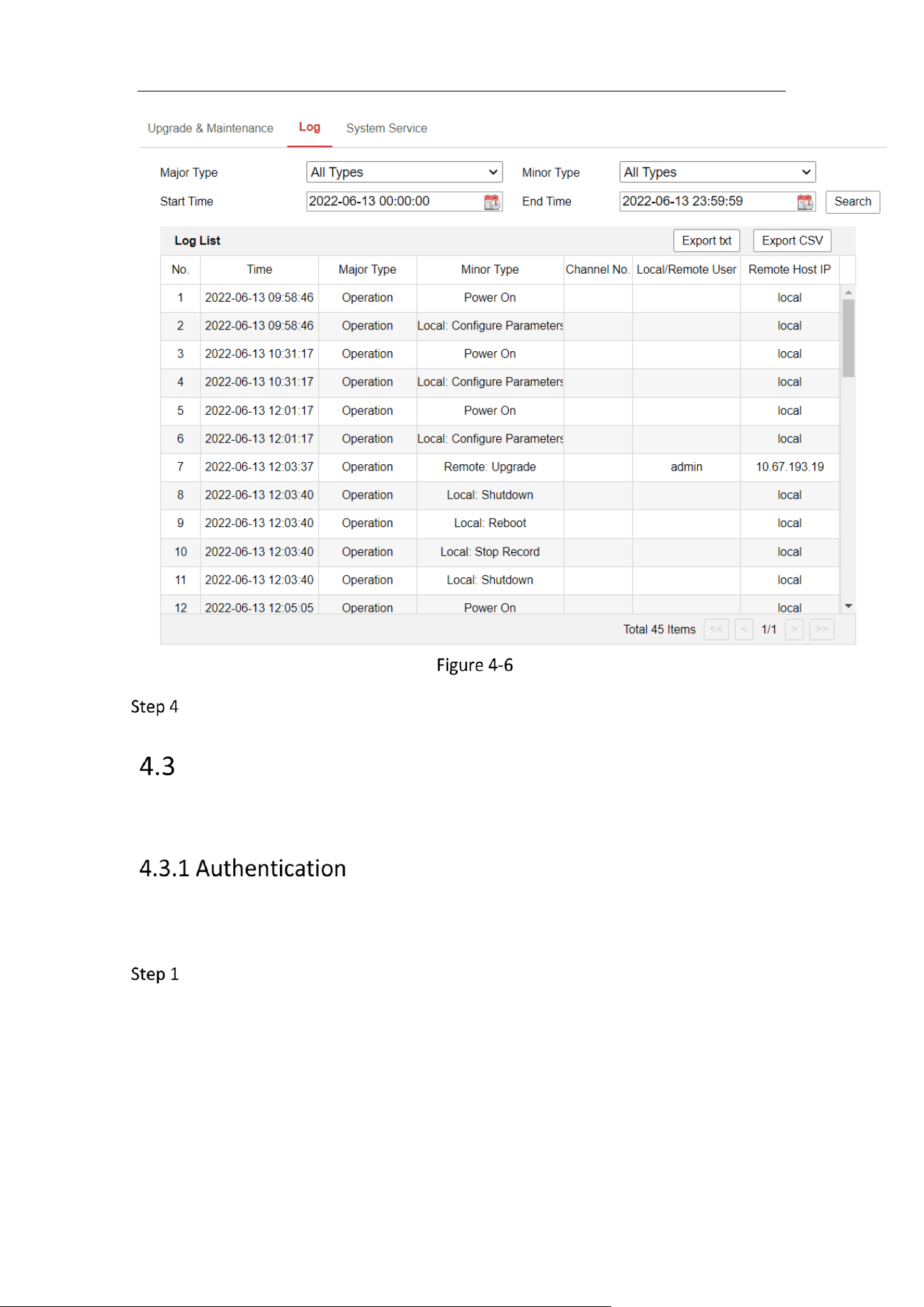
Mobile Network Camera • User Manual
24
Log Searching
To export the log files, click Export to save the log files.
Security
Configure the parameters, including Authentication, IP Address Filter, and Security
Service from security interface.
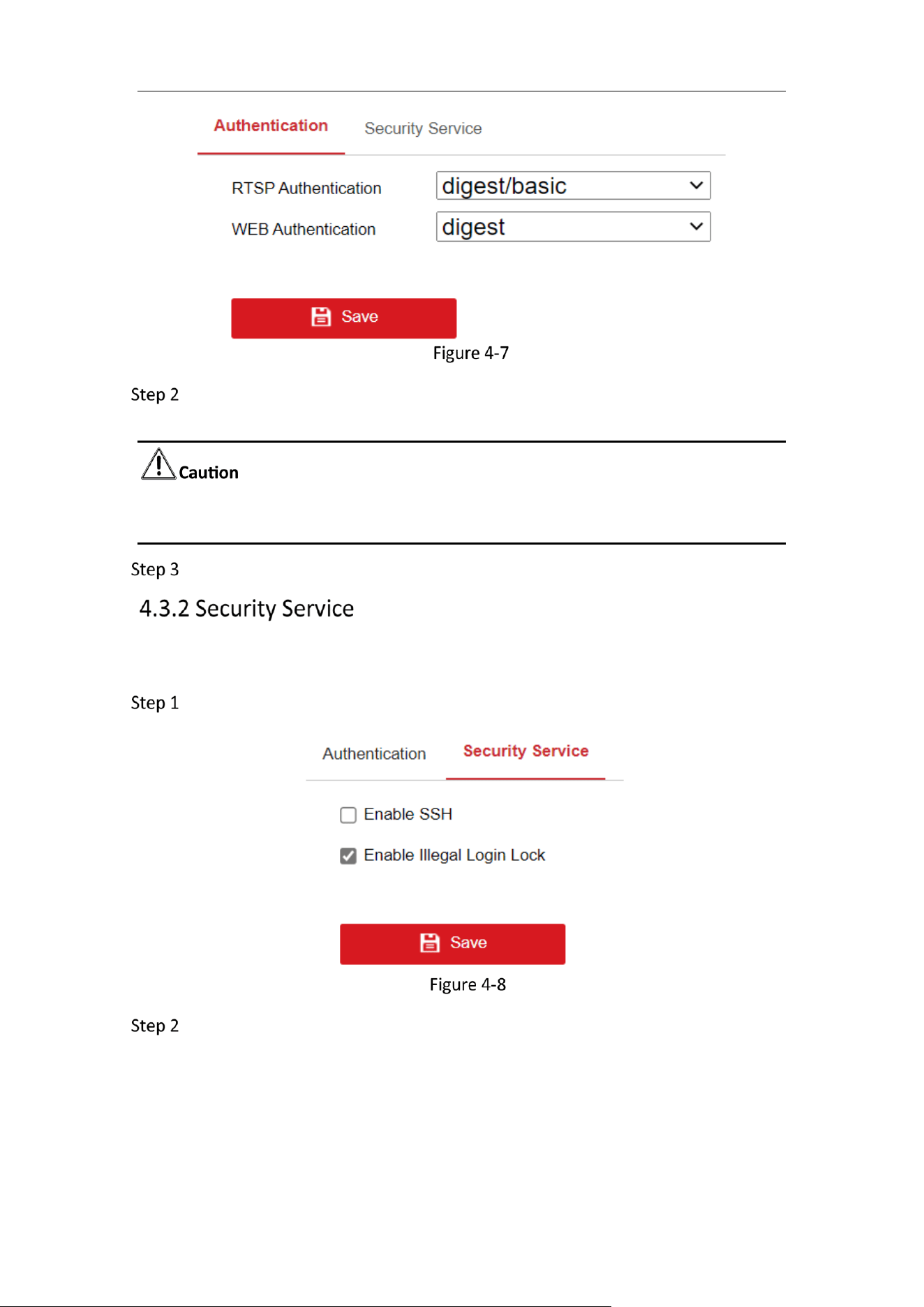
Purpose:
You can specifically secure the stream data of live view.
Go to Configuration > System > Security > Authentication.
Mobile Network Camera • User Manual
25
Authentication
Configure authentication method for RTSP authentication and WEB
authentication.
Digest is the recommended authentication method for better data security. You
must be aware of the risk if you adopt basic as the authentication method.
Click Save.
To enable the remote login, and improve the data communication security, the camera
provides the security service for better user experience.
Go to Configuration > System > Security > Security Service.
Security Service
Check the checkbox of Enable Illegal Login Lock and SSH.
Illegal Login Lock is used to limit the user login attempts. Login attempt from the IP
address is rejected if admin user performs 7 failed user name/password attempts (5
times for the operator/user).
SSH allows remote login, which increases the web security risk. Be cautious to enable
this item.
Mobile Network Camera • User Manual
26
If the IP address is rejected, you can try to login the device after 30 minutes.
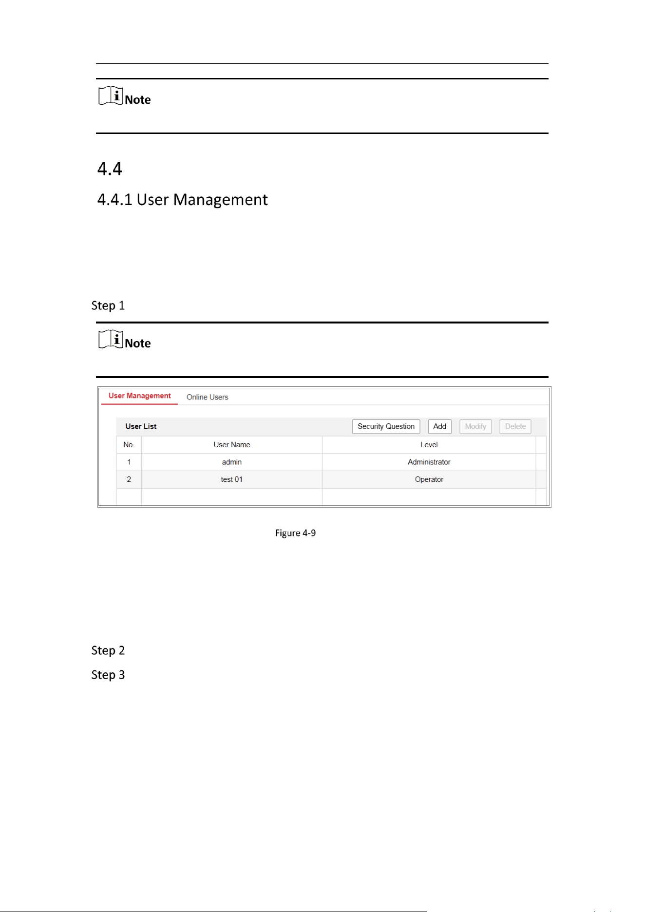
User Management
Administrator
The admin user can add, delete or modify user accounts, and grant them different
permissions. We highly recommend you manage the user accounts and permissions
properly.
Go to Configuration > System > User Management.
Admin password if required for adding and modifying a user account.
User Management Interface
Adding a User
The admin user has all permissions by default and can create/modify/delete other
accounts.
The admin user cannot be deleted and you can only change the admin password.
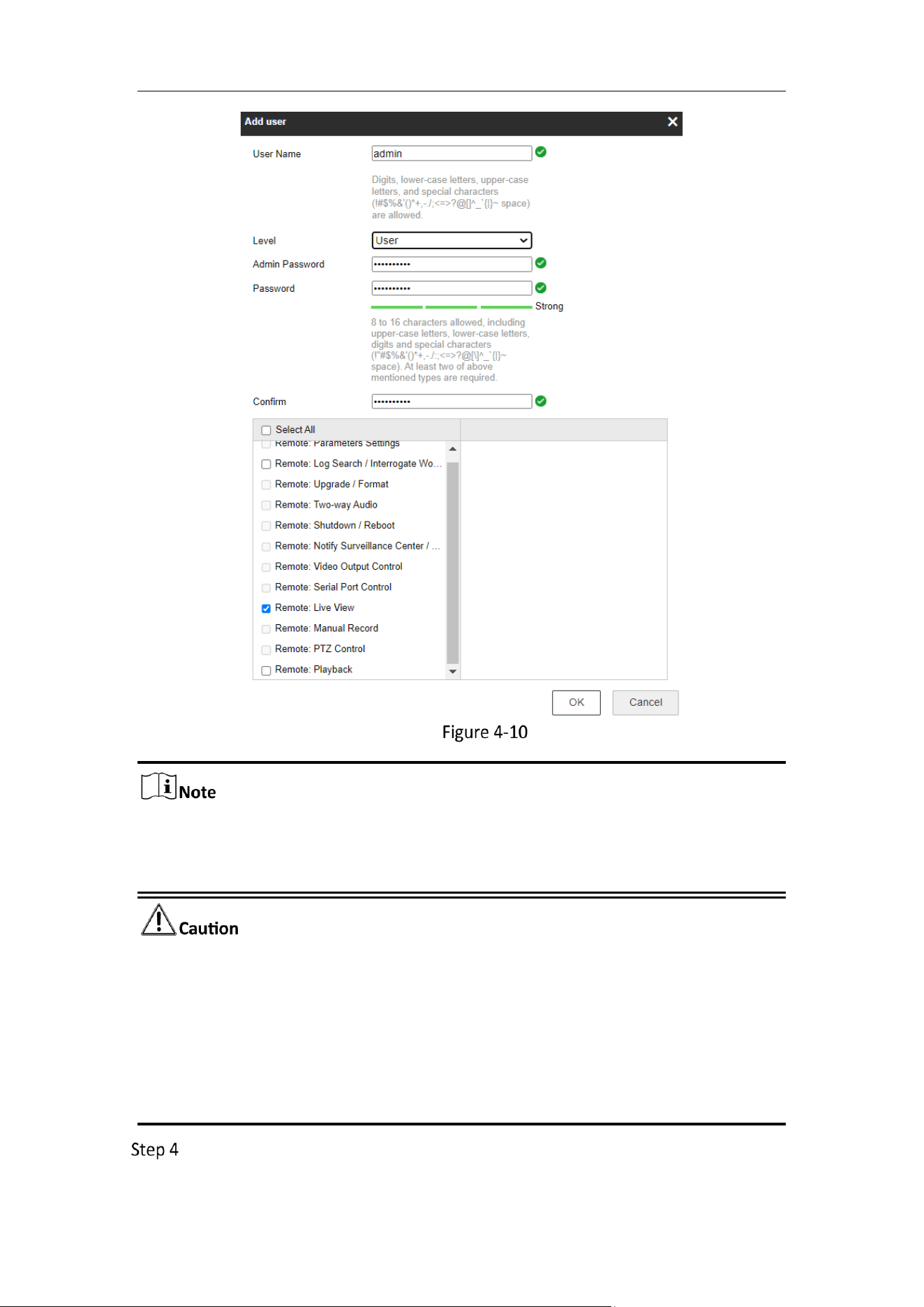
Click Add to add a user.
Input the Admin Password, User Name, select Level and input Password.
Mobile Network Camera • User Manual
27
Add a User
Up to 16 user accounts can be created.
Users of different levels own different default permissions. Operator and user are
selectable.
Strong Password recommended
We highly recommend you create a strong password of your own choosing (using
a minimum of 8 characters, including at least three of the following categories:
upper case letters, lower case letters, numbers, and special characters) in order to
increase the security of your product. And we recommend you reset your
password regularly, especially in the high security system, resetting the password
monthly or weekly can better protect your product.
You can check or uncheck the permissions for the new user.
Mobile Network Camera • User Manual
28
Click OK to finish the user addition.
Modify a User
Left-click to select the user from the list and click Modify.
Modify the User Name, Level and Password.
Strong Password recommended
We highly recommend you create a strong password of your own choosing (using
a minimum of 8 characters, including at least three of the following categories:
upper case letters, lower case letters, numbers, and special characters) in order to
increase the security of your product. And we recommend you reset your
password regularly, especially in the high security system, resetting the password
monthly or weekly can better protect your product.
You can check or uncheck the permissions.
Click OK to finish the user modification.
Deleting a User
1) Click to select the user you want to delete and click Delete.
2) Click OK on the pop-up dialogue box to confirm the deletion.
Operator/User
Operator or user can modify password. Old password is required for this action.
Purpose:
Security question is used to reset the admin password when admin user forgets the
password.
Set Security Questions
You can set the security questions during camera activation. Or you can set the
function at user management interface.
Security question setting is not cleared when you restore the camera (not to default).
Steps:
Go to Configuration > System > User Management.
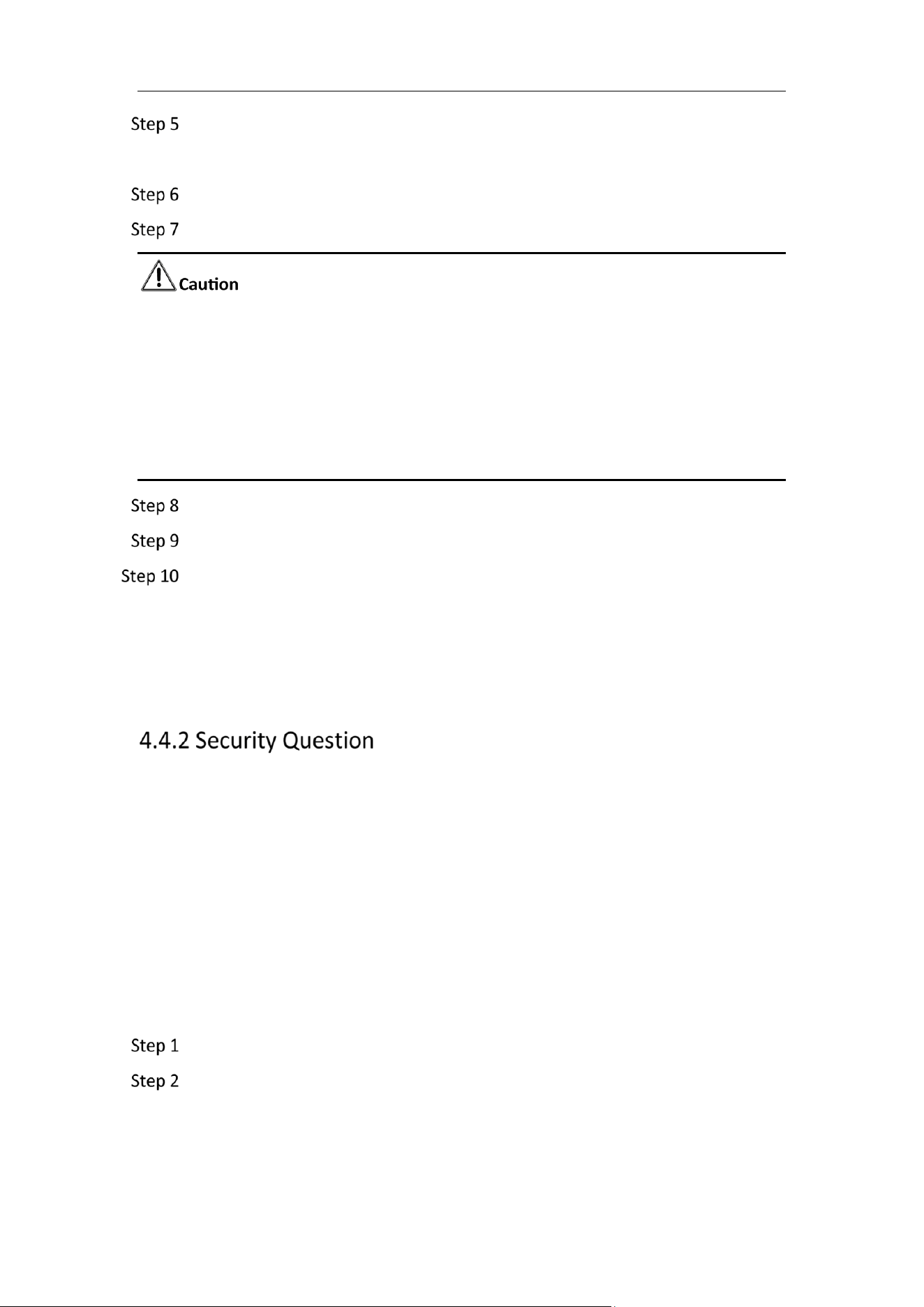
Click Account Security Question.
Mobile Network Camera • User Manual
29
Account Security Question
Select questions and input answers.
Click OK to save the settings.
Reset Admin Password:
Before you start:
The PC used to reset password and the camera should belong to the same IP address
segment of the same LAN.
Steps:
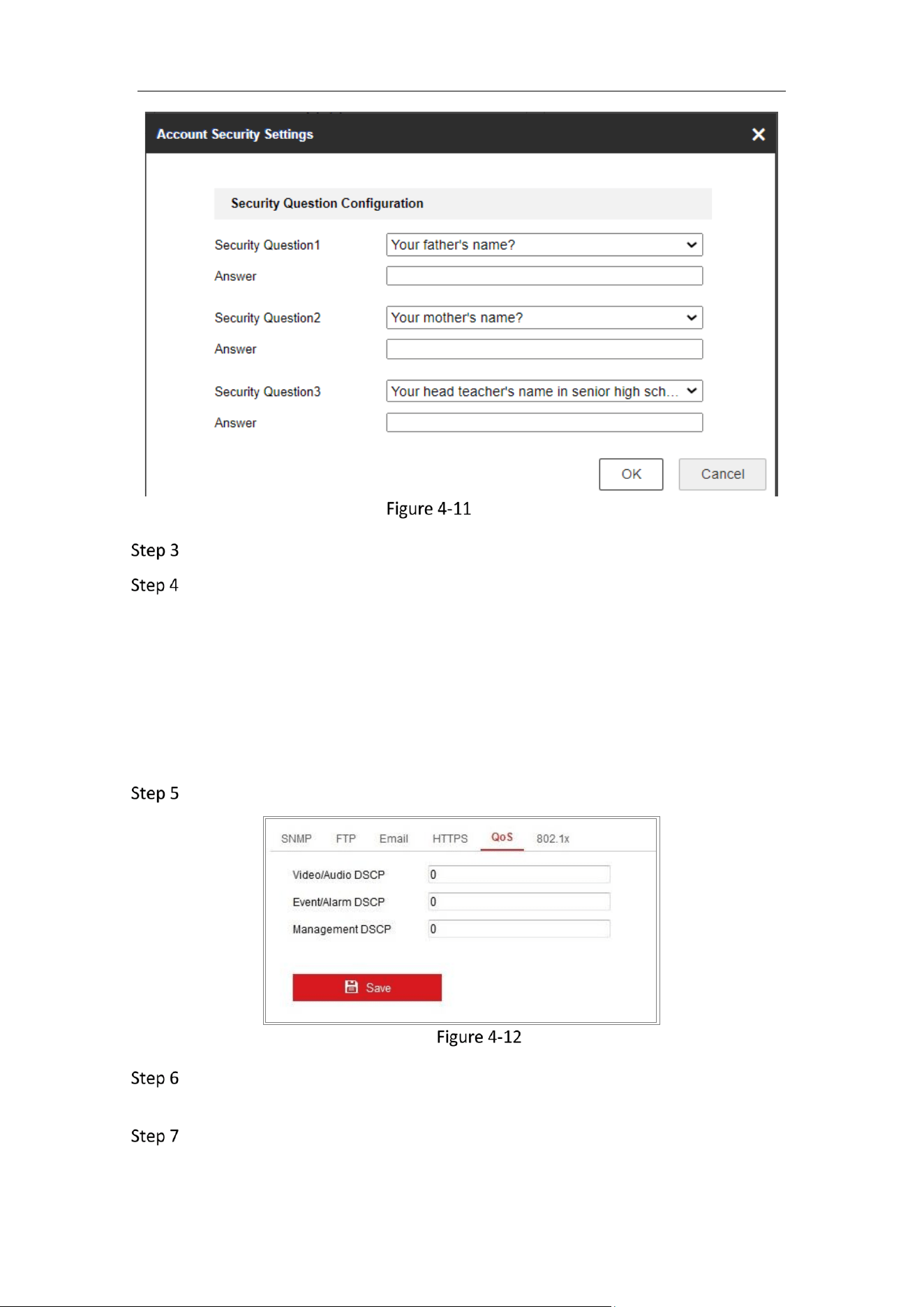
Go to Configuration > Network > Advanced Settings > QoS
QoS Settings
Configure the QoS settings, including Video/Audio DSCP, Event/Alarm DSCP and
Management DSCP.
The valid value range of the DSCP is 0 to 63. The bigger the DSCP value is, the
higher the priority is.
Mobile Network Camera • User Manual
30
DSCP refers to the Differentiated Service Code Point; and the DSCP value is used
in the IP header to indicate the priority of the data.
Click Save to save the settings.
A reboot is required for the settings to take effect.
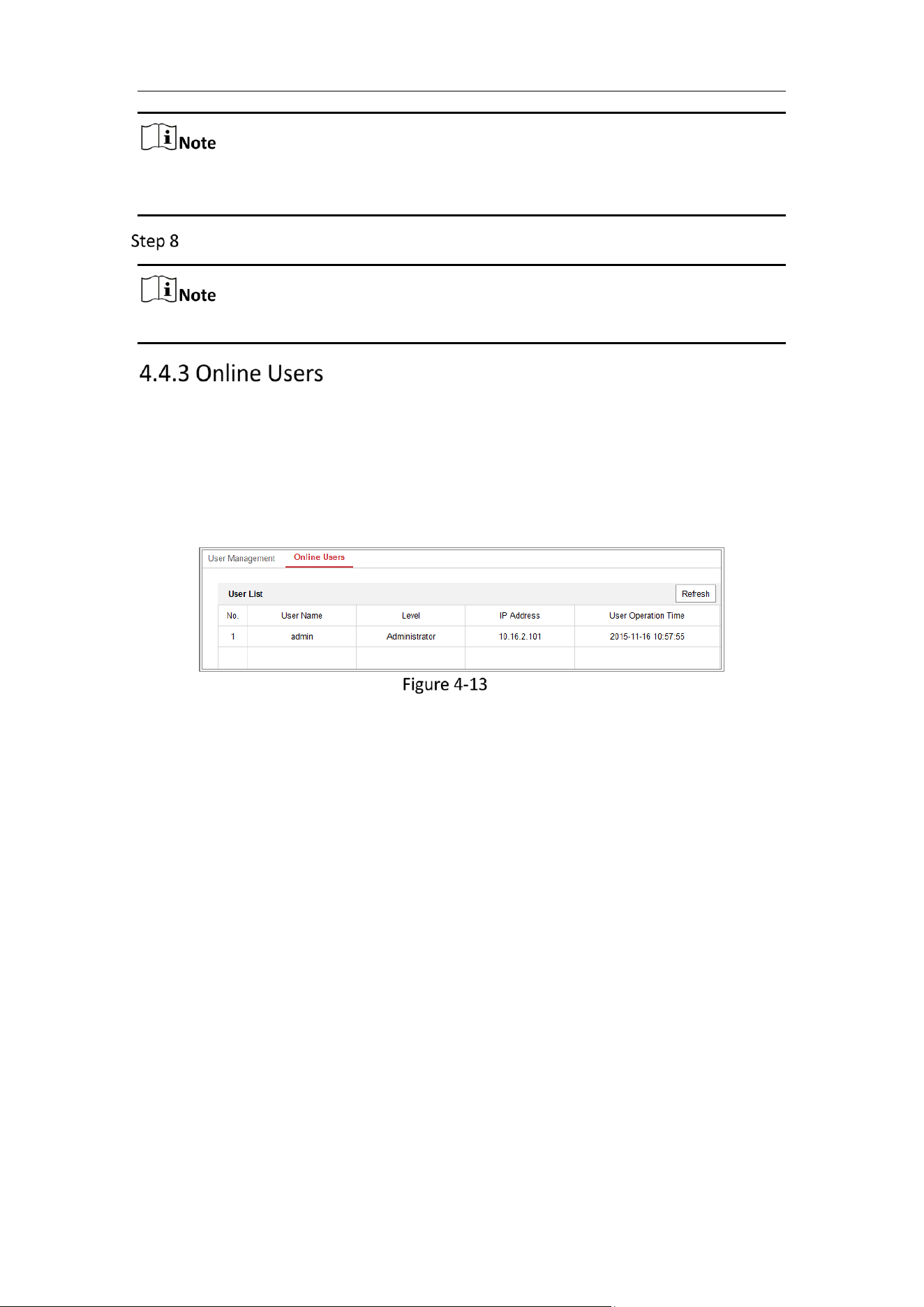
Purpose:
You can see the current users who are visiting the device through this interface. User
information, such as user name, level, IP address, and operation time, is displayed in
the User List.
Click Refresh to refresh the list.
View the Online Users
Mobile Network Camera • User Manual
31
Chapter 5 Network Settings
Purpose:
Follow the instructions in this chapter to configure the basic settings and advanced
settings.
Basic Settings
Purpose:
You can configure the parameters, including TCP/IP, Port, and Multicast, etc., by
following the instructions in this section.
Purpose:
TCP/IP settings must be properly configured before you operate the camera over
network. The camera supports both the IPv4 and IPv6. Both versions can be configured
simultaneously without conflicting to each other, and at least one IP version should be
configured.
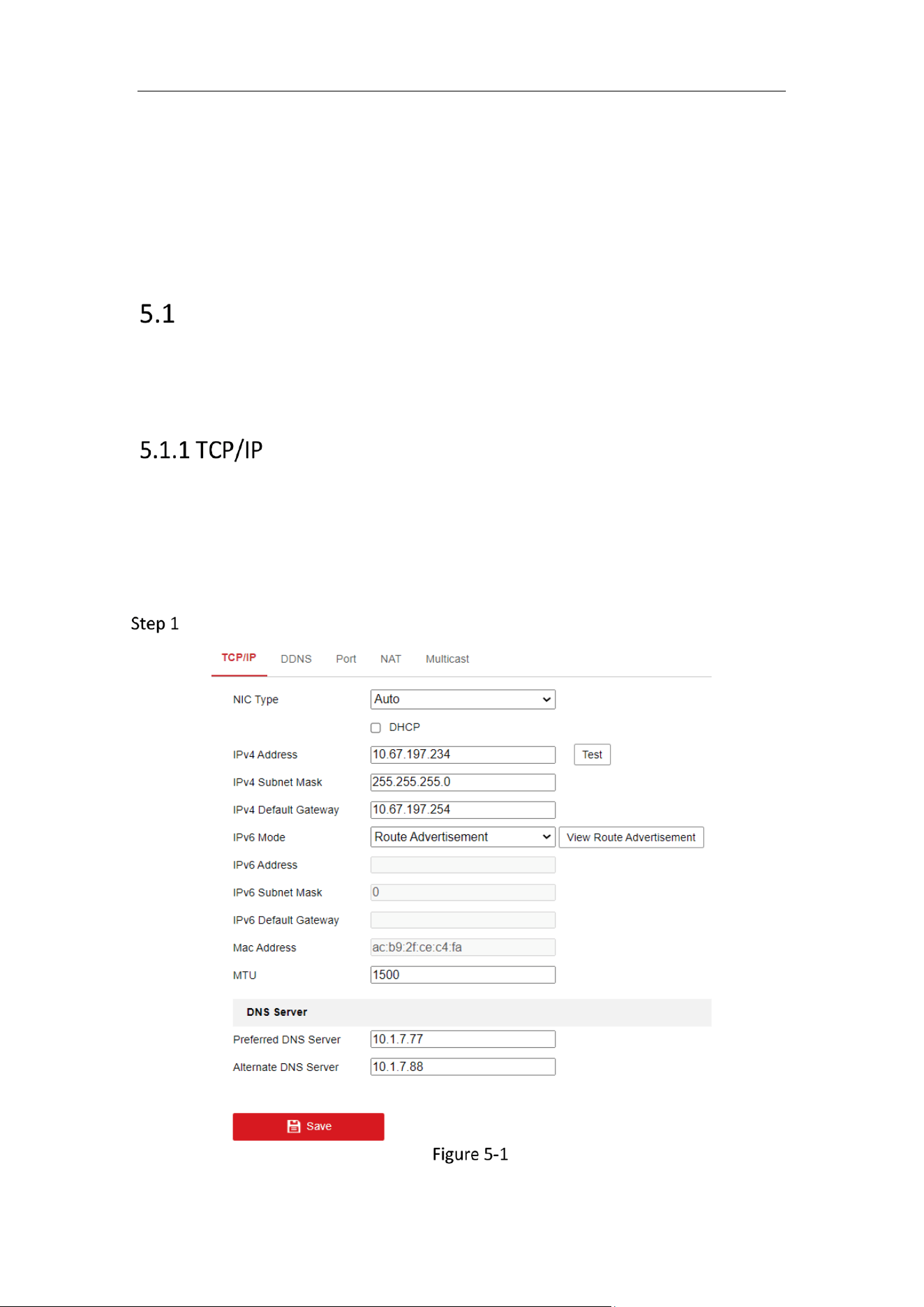
Go to Configuration > Network > Basic Settings > TCP/IP.
TCP/IP Settings
Mobile Network Camera • User Manual
32
Configure the basic network settings, including the NIC Type, IPv4 or IPv6
Address, IPv4 or IPv6 Subnet Mask, IPv4 or IPv6 Default Gateway, and MTU
settings.
Configure the DNS server. Input the preferred DNS server, and alternate DNS
server.
Click Save to save the above settings.
The valid value range of MTU is 1280 to 1500.
A reboot is required for the settings to take effect.
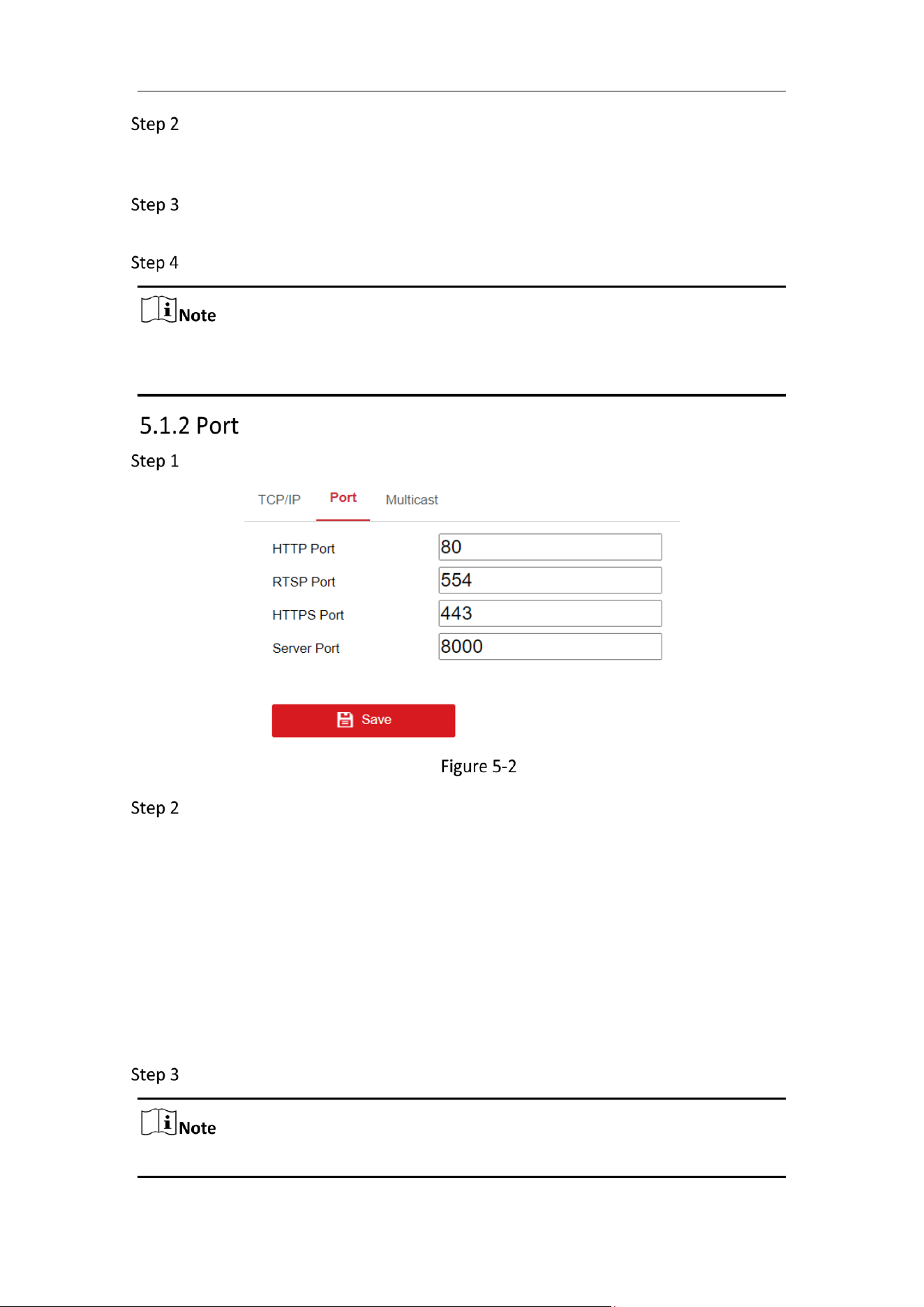
Go to Configuration > Network > Basic Settings > Port.
Port Settings
Set the ports of the camera.
HTTP Port: The default port number is 80, and it can be changed to any port No. which
is not occupied.
RTSP Port: The default port number is 554 and it can be changed to any port No. ranges
from 1 to 65535.
HTTPS Port: The default port number is 443, and it can be changed to any port No.
which is not occupied.
Server Port: The default server port number is 8000, and it can be changed to any port
No. ranges from 2000 to 65535.
Click Save to save the settings.
A reboot is required for the settings to take effect.
Mobile Network Camera • User Manual
33
The Multicast sends a stream to the multicast group address and allows multiple
clients to acquire the stream at the same time by requesting a copy from the multicast
group address. Before utilizing this function, you have to enable the Multicast function
of your router.
Go to Configuration > Network > Basic Settings > Multicast.
Configure the parameters for Multicast.
IP Address: The IP address of the multicast host.
The range for multicast IP address is 224.0.0.19~239.255.255.255
Stream Type
Choose the type of stream according to your needs.
Video Port and Audio Port
For video and audio transmission.
For some models, the Third Stream is not enabled by default. Go to System >
Maintenance > System Service> Software to enable the function is required.
The main stream is usually for recording and live view with good bandwidth, and
the sub-stream can be used for live view when the bandwidth is limited.
You can customize the following parameters for the selected stream type.
Click Save.
Advanced Settings
Purpose:
You can configure the parameters, including, HTTPS, integration protocol, network
service and https listening etc., by following the instructions in this section.
Purpose:
HTTPS provides authentication of the web site and its associated web server, which
protects against Man-in-the-middle attacks.
If HTTPS is enabled by default, the camera creates an unsigned certificate
automatically. When you visit the camera via HTTPS, the web browser will send a
Mobile Network Camera • User Manual
34
notification about the certificate issue. Install a signed-certificate to the camera to
cancel the notification.
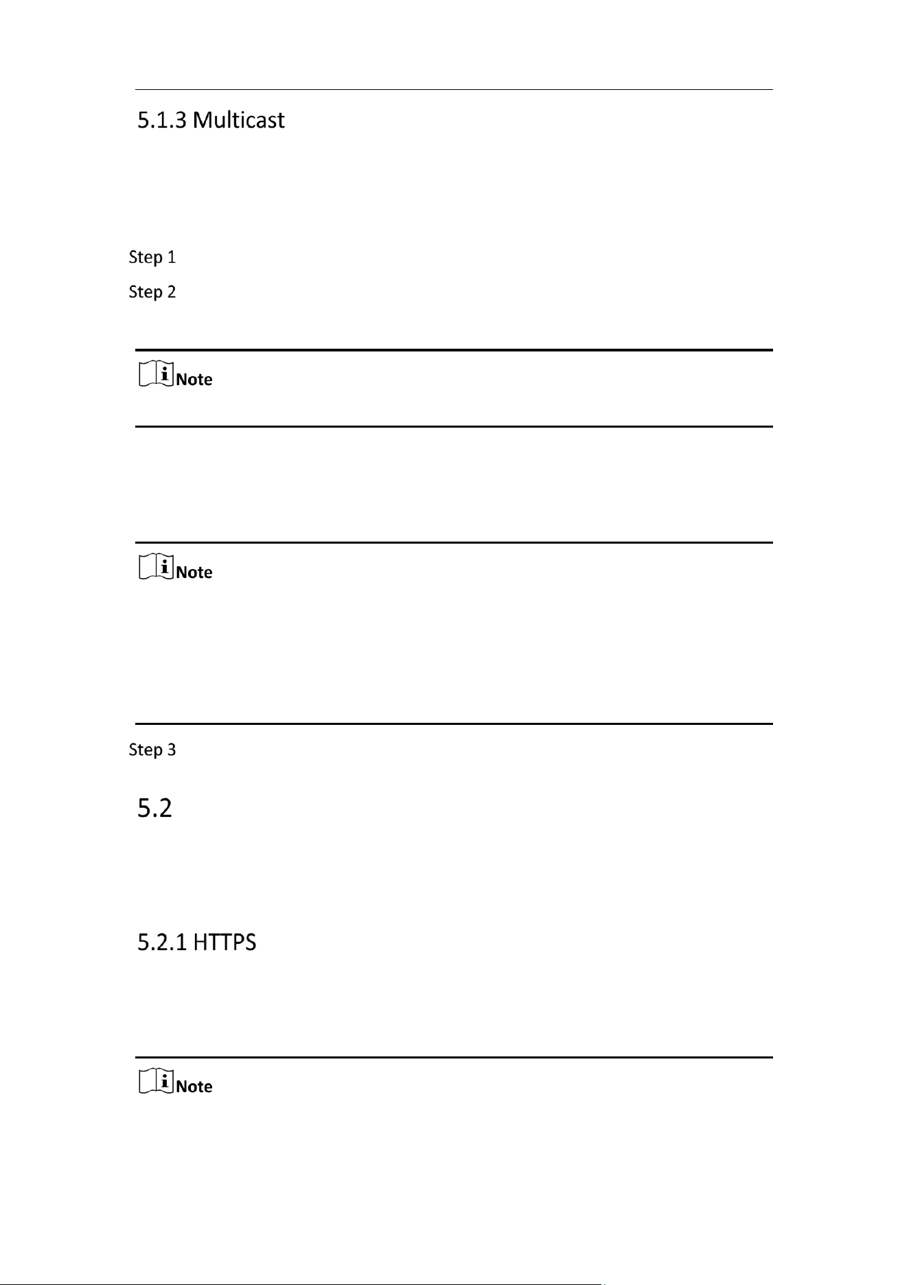
G to Configuration > Network > Advanced Settings > HTTPS.
Check Enable to access the camera via HTTP or HTTPS protocol.
Check Enable HTTPS Browsing to access the camera only via HTTPS protocol.
HTTPS Configuration Interface
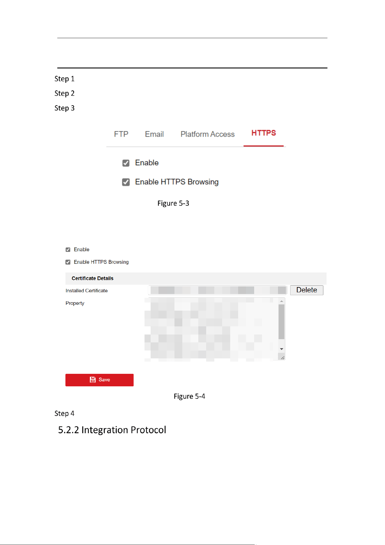
There will be the certificate information after your successfully creating and installing
the certificate.
Installed Certificate
Click Save to save the settings.
Purpose:
If you need to access to the camera through the third party platform, you can enable
CGI function. And if you need to access to the device through ONVIF protocol, you can
configure ONVIF user in this interface. Refer to ONVIF standard for detailed
configuration rules.
Mobile Network Camera • User Manual
35
ONVIF
Check the Enable ONVIF checkbox to enable the function.
Add ONVIF users. Up to 32 users are allowed.
Set the user name and password, and confirm the password. You can set the
user as media user, operator, and administrator.
ONVIF user account is different from the camera user account. You have set ONVIF
user account independently.
Click Save to save the settings.
User settings of ONVIF are cleared when you restore the camera.
You can control the ON/OFF status of certain protocol that the camera supports.
Keep unused function OFF for security concern.
Supported functions vary according to camera models.
SDK Service and Enhanced SDK Service
If you want to add the device to the client software, you should enable SDK Service or
Enhanced SDK Service.
− SDK Service: SDK protocol is used.
− Enhanced SDK Service: SDK over TLS protocol is used. Communication
between the device and the client software is secured by using TLS
(Transport Layer Security) protocol.
TLS (Transport Layer Security)
The device offers TLS 1.1 and TLS 1.2. Enable one or more protocol versions according
to your need.
Mobile Network Camera • User Manual
36
Chapter 6 Video and Audio Settings
Purpose:
Follow the instructions below to configure the video setting, audio settings, ROI,
Display info. on Stream, etc.
For certain camera models, you can configure parameters for available video streams,
for example, the main stream, the sub-stream, etc. And you can also customize
additional video streams for further needs.
Video Settings
Go to Configuration > Video/Audio > Video
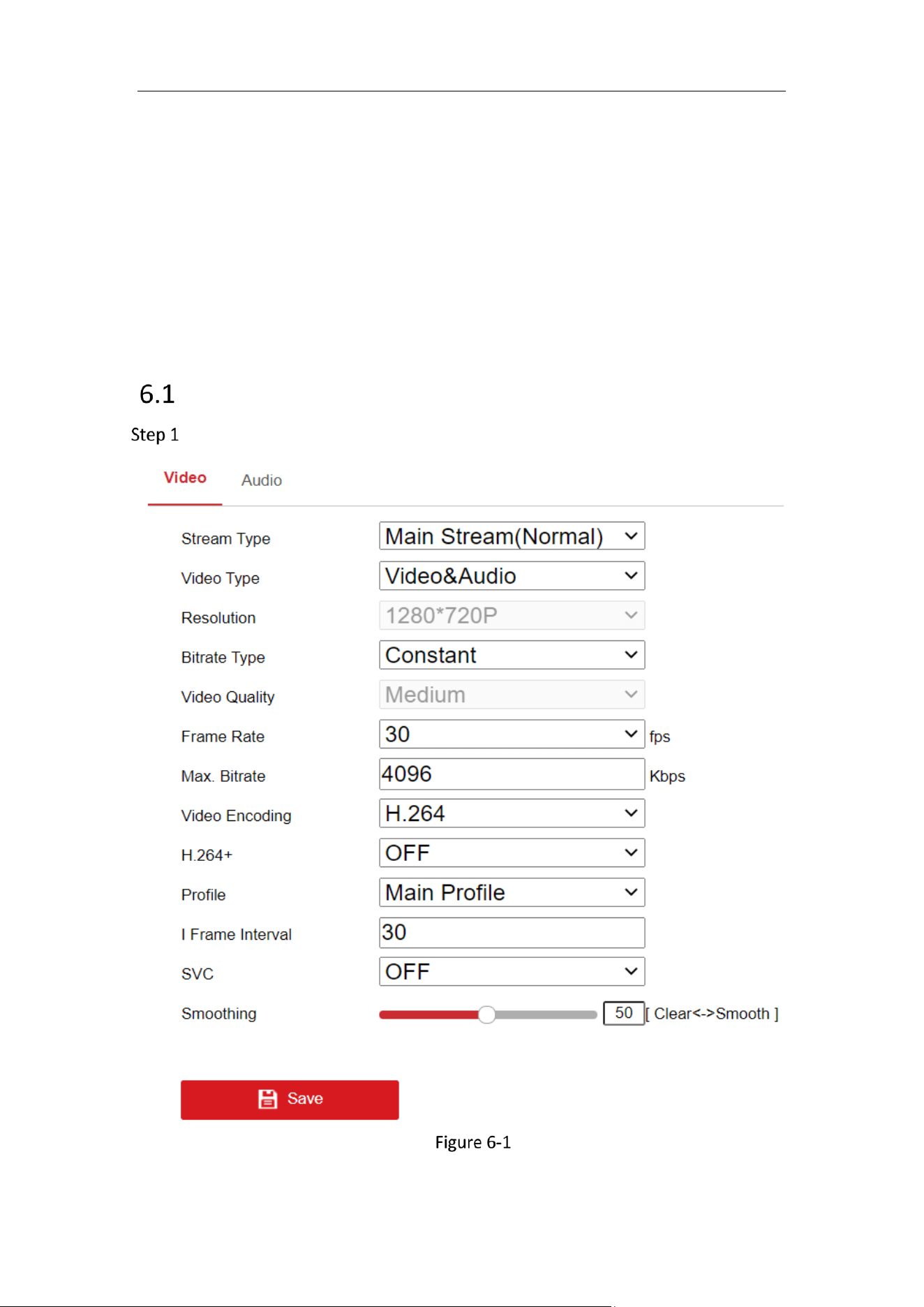
Video Settings

Mobile Network Camera • User Manual
37
Select the Stream Type.
Supported stream types are listed in the drop-down list.
The main stream is usually for recording and live view with good bandwidth, and
the sub-stream can be used for live view when the bandwidth is limited.
You can customize the following parameters for the selected stream type.
Video Type:
Select the stream type to video stream, or video & audio composite stream. The audio
signal will be recorded only when the Video Type is Video & Audio.
Resolution:
Select the resolution of the video output.
Bitrate Type:
Select the bitrate type to constant or variable.
Video Quality:
When bitrate type is selected as Constant, the video quality will be set as Medium.
When bitrate type is selected as Variable, 6 levels of video quality are selectable.
Frame Rate:
Set the frame rate. The frame rate is to describe the frequency at which the video
stream is updated and it is measured by frames per second (fps). A higher frame rate
is advantageous when there is movement in the video stream, as it maintains image
quality throughout.
Max. Bitrate:
Set the max. bitrate from 32 to 16384 Kbps. The higher value corresponds to the higher
video quality, which requires the better bandwidth.
The maximum limit of the max. bitrate value varies according to different camera
platforms. For certain cameras, the maximum limit is 8192 Kbps or 12288 Kbps.
Video Encoding:
The camera supports video encodings types such as H.264, and H.265. Supported
encoding type for different stream types may differ. H.265 is a new encoding
technology. Compared with H.264, it reduces the transmission bitrate under the same
resolution, frame rate and image quality.

Mobile Network Camera • User Manual
38
Selectable video encoding types may vary according to different camera modes.
H.264+ and H.265+:
− H.264+: If you set the main stream as the stream type, and H.264 as the video
encoding, you can see H.264+ available. H.264+ is an improved compression
coding technology based on H.264. By enabling H.264+, users can estimate the
HDD consumption by its maximum average bitrate. Compared to H.264, H.264+
reduces storage by up to 50% with the same maximum bitrate in most scenes.
− H.265+: If you set the main stream as the stream type, and H.265 as the video
encoding, you can see H.265+ available. H.265+ is an improved compression
coding technology based on H.265. By enabling H.265+, users can estimate the
HDD consumption by its maximum average bitrate. Compared to H.265, H.265+
reduces storage by up to 50% with the same maximum bitrate in most scenes.
You need to reboot the camera if you want to turn on or turn off the H.264+/H.265+.
If you switch from H.264+ to H.265+ directly, and vice versa, a reboot is not required
by the system.
Upgrade your video player to the latest version if live view or playback does not
work properly due to compatibility.
With H.264+/H.265+ enabled, the parameters such as profile, I frame interval,
video quality, and SVC are greyed out.
With H.264+/H.265+ enabled, some functions are not supported. For those
functions, corresponding interfaces will be hidden.
H.264+/H.265+ can spontaneously adjust the bitrate distribution according the
requirements of the actual scene in order to realize the set maximum average
bitrate in the long term. The camera needs at least 24 hours to adapt to a fixed
monitoring scene.
Max. Average Bitrate:
When you set a maximum bitrate, its corresponding recommended maximum average
bitrate will be shown in the Max. Average Bitrate box. You can also set the maximum
average bitrate manually from 32 Kbps to the value of the set maximum bitrate.
Profile:
When you select H.264 or H.265 as video encoding, you can set the profile. Selectable
profiles vary according to camera models.
I Frame Interval:
Set I Frame Interval from 1 to 400.
SVC:
Mobile Network Camera • User Manual
39
Scalable Video Coding is an extension of the H.264/AVC and H.265 standard. Select
OFF/ON to disable/enable the SVC function. Select Auto and the device will
automatically extract frames from the original video when the network bandwidth is
insufficient.
Smoothing:
It refers to the smoothness of the stream. The higher value of the smoothing is, the
better fluency of the stream will be, though, the video quality may not be so
satisfactory. The lower value of the smoothing is, the higher quality of the stream will
be, though it may appear not fluent.
Click Save to save the settings.
The video parameters vary according to different camera models. Refer to the
actual display page for camera functions.
Audio
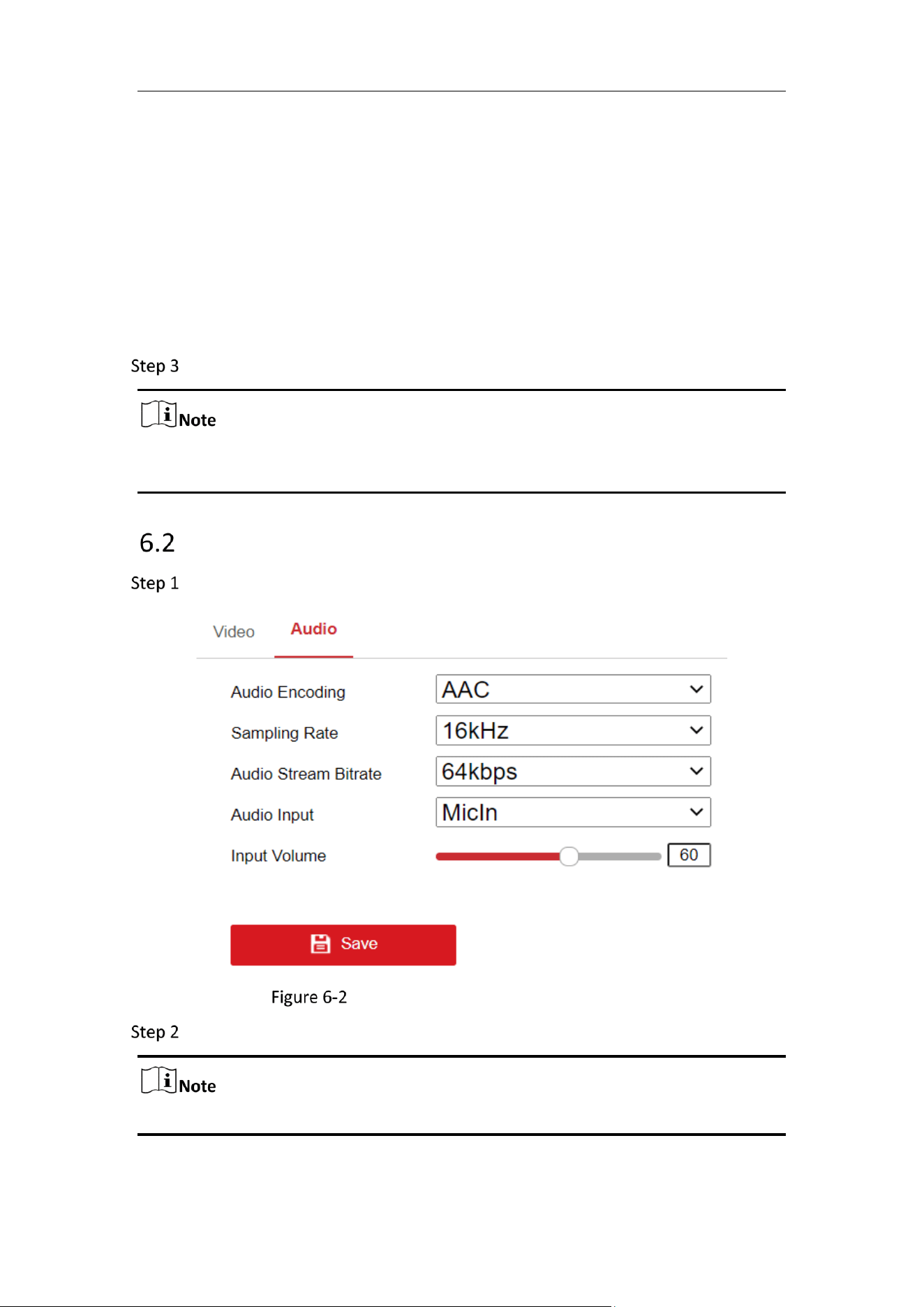
Go to Configuration > Video/Audio > Audio.
Audio Settings
Configure the following settings.
Audio settings may vary according to different camera models.
Audio Encoding: G.722.1, G.711 ulaw, G.711 alaw, G.726_A and PCM are selectable.
For PCM, the Sampling Rate can be set.

Mobile Network Camera • User Manual
40
Audio Input: MicIn is selectable for the connected microphone.
Sampling Rate: Only 16 kHz is supported.
Input Volume: 0-100 adjustable.
Environmental Noise Filter: Set it as OFF or ON. When the function is enabled, the
noise in the environment can be filtered to some extent.
Click Save to save the settings.
Mobile Network Camera • User Manual
41
Chapter 7 OSD Settings
Purpose:
Follow the instructions in this chapter to configure the image parameters, including
display settings and OSD settings.
Purpose:
You can customize the camera name, time/date format, display mode, and OSD size
displayed on the live view.
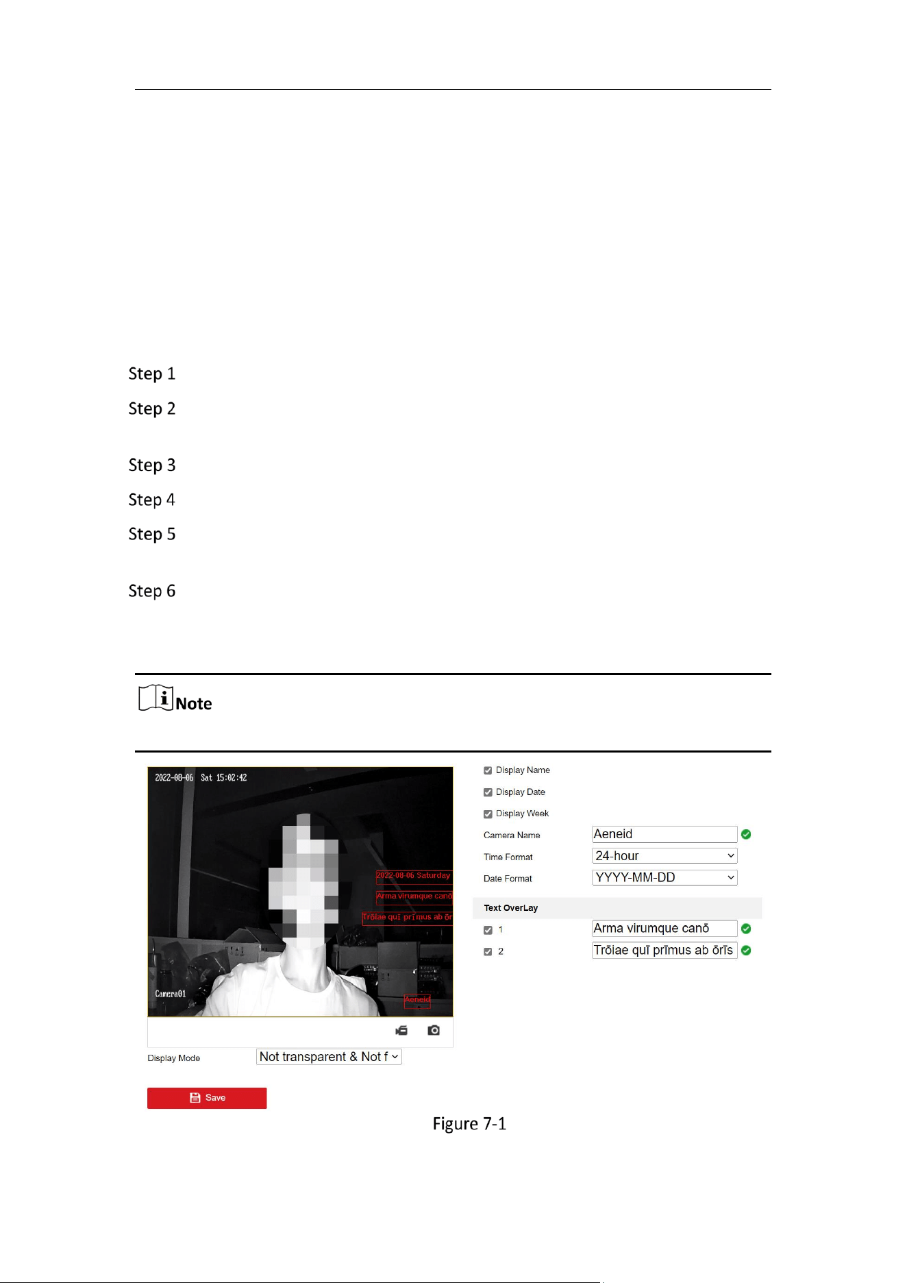
Go to Configuration > Image > OSD Settings.
Check the corresponding checkbox to select the display of camera name, date
or week if required.
Edit the camera name in the text field of Camera Name.
Select from the drop-down list to set the time format and date format.
Select from the drop-down list to set the time format, date format, and display
mode.
Configure the text overlay settings.
1) Check the checkbox in front of the textbox to enable the on-screen display.
2) Input the characters in the textbox.
Up to 2 text overlays are configurable.
OSD Settings
Mobile Network Camera • User Manual
42
Adjust the position and alignment of text frames.
Use the mouse to click and drag text frames in the live view window to adjust their
positions.
The alignment adjustment is only applicable to Text Overlay items.
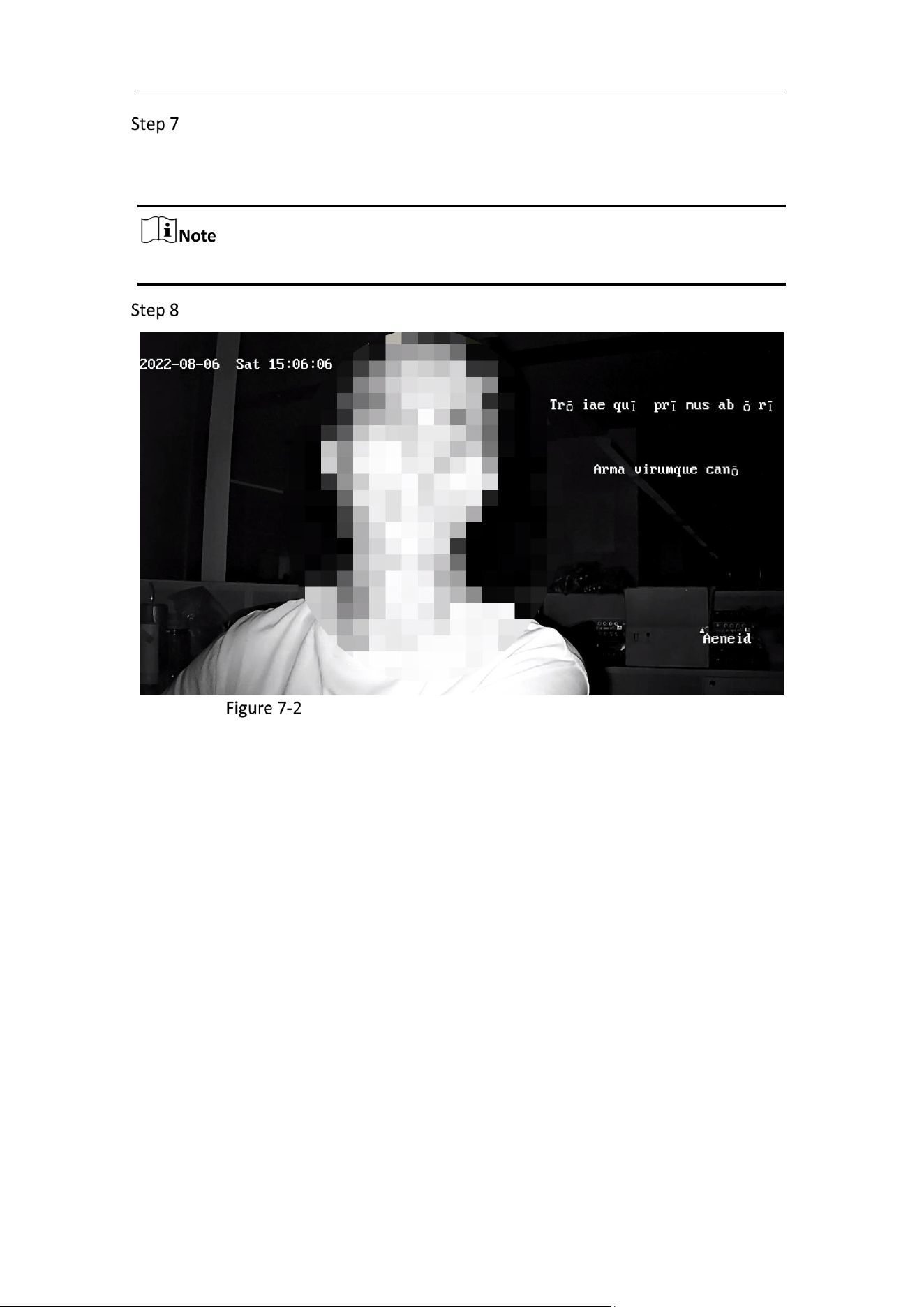
Click Save to save the settings and view the result on the Live View.
4 Lines of Text Overlay: Not Transparent&Not Flashing
Mobile Network Camera • User Manual
43
Chapter 8 Storage Settings
Before you start:
To configure record settings, make sure that you have the network storage device or
local storage device configured.
Record Schedule
Purpose:
You can configure the scheduled recording. The captured picture can be stored in the
local storage.
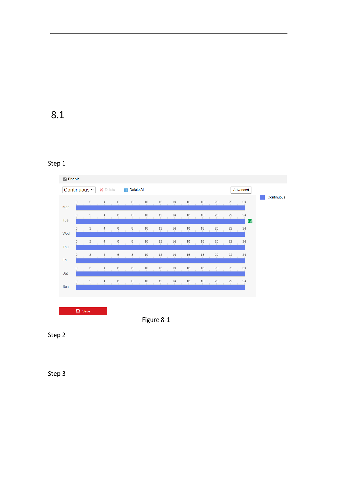
Go to Configuration > Storage > Schedule Settings > Record Schedule.
Capture Schedule Interface
Select the Record Type. The camera currently supports only Continuous.
Continuous
The video will be recorded automatically according to the time of the schedule.
Click Advanced to set the advanced parameters.
Mobile Network Camera • User Manual
44
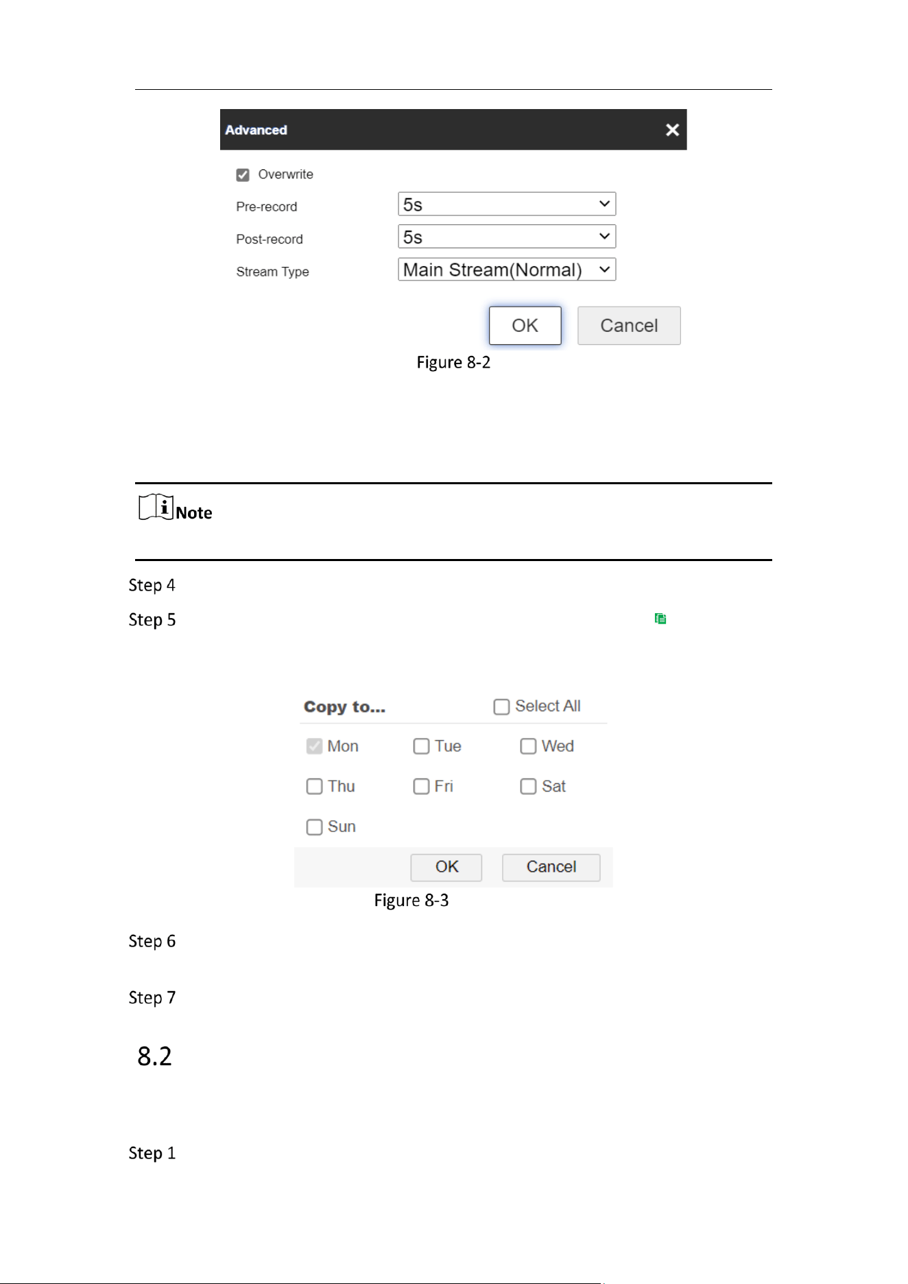
Advanced Setting
Stream Type: Select the stream type for recording.
Pre- and Post-record: the time that camera records before and after events.
Stream Type: only supports Main Stream.
The record parameter configurations vary depending on the camera model.
Click-and-drag the mouse on the time bar to set the record schedule.
(optional) To duplicate the setting of one day to another, click that appears
when the mouse hover over the time bar, and choose the date to apply the same
setting. Check Select All if the setting is to be applied to all dates.
Copy Setting to Another Date
Delete the setting of one day by selecting that date and click Delete. You can
also click Delete All to remove all settings.
Click Save to save the settings.
Capture Schedule and Capture Parameters
The setting of Capture Schedule is the same as the Record Schedule. The format,
resolution, quality and interval of capture can be set on Capture Parameters.
Go to Capture Parameters tab to configure the capture parameters.
Mobile Network Camera • User Manual
45
1) Check the Enable Timing Snapshot checkbox to enable continuous
snapshot.
2) Select the picture format, resolution, quality and capture interval.
Set Capture Parameters
Click Save to save the settings.
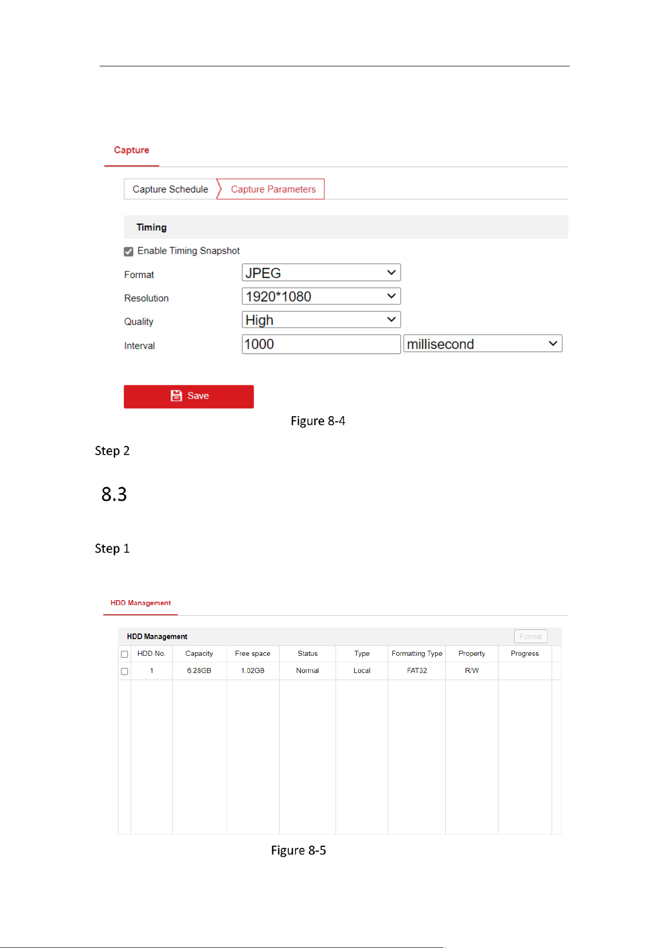
Storage Management
Steps:
Go to Configuration > Storage > Storage Management > HDD Management, in
which you can view the capacity, free space, status, type and property of the
disk.
Storage Management Interface

Mobile Network Camera • User Manual
46
If the status of the disk is Uninitialized, check the corresponding checkbox to
select the disk and click Format to start initializing the disk.
When the initialization completed, the status of disk will become Normal.
Advanced Settings
Currently, the advanced settings only support the setting of whether to print logs.
Go to Configuration > Storage > Storage Management > HDD Management
Advanced Settings > Other.
Check Enable Print Log.

Mobile Network Camera • User Manual
47
Chapter 9 Driving Status Monitoring Settings
Driving Status Monitoring
To the monitor driving status of the vehicle, you need to configure the sensitivity, inhibition time and
speed threshold.
The setting items of all DSM detection are the same, and in the following, the setting is illustrated
with the case of Distraction Prompt Detection.
Go to Configuration > Driving Status Monitoring.
Check Enable to enable the Driving Status Monitoring function and check the Distraction
Prompt Detection.
Check Enable Primary Filter and Secondary Filter to start setting these parameters by clicking
and dragging and bar, or putting in a number to set the parameter.
Sensitivity
Sensitivity refers to the time between the DSM detection and the alarm and it is measured in
seconds.
Inhibition Time
Inhibition time refers to the interval between two alarms.
Alarm Volume
Alarm Volume refers to how loud the alarm is and the highest degree is 9.
Speed Threshold
− The speed range for primary filter is 1-100 km/h and the second filter 10-100 km/h. The value of
the second filter must be higher than the primary filer.
− The default speed threshold for primary filter is 30 km/h and the second filter is 50 km/h.
− When the vehicle speed is lower than the speed threshold of the primary filter, then no alarm
will be triggered.
− When the vehicle speed is between the speed threshold of the primary and secondary filter,
then the setting of the primary filter will take effect.
− When the vehicle speed is above the speed threshold of the secondary filter, then the setting of
the secondary filter will take effect.
Check the Audible Alarm Enable to adjust the Alarm Volume.
Click Save to save the settings.

Mobile Network Camera • User Manual
48
Advanced Parameters
Go to Configuration > Driving Status Monitoring.
Click Advanced Parameters to configure the video threshold of the Distraction Prompt
Detection, Fatigue Driving (Closing Eyes) Detection. When the above mentioned behavior is
detected to be higher than the configured value, then an alarm will be triggered.
Demo mode:
The demo mode is for demonstrating the alarm effects and for calibration. On demo mode:
− The DSM detection alarm will be switched on regardless of the speed threshold and will be
easier to be triggered as filter configurations are disabled.
− the DSM detection algorithm uses the internal default value, regardless of the external
configuration;
Click Default to restore default parameters.
Click Save to save the settings.
Mobile Network Camera • User Manual
49
Chapter 10 Access to the Network Camera
Purpose:
This section explains how to connect the network camera to the WAN with a static IP or a dynamic
IP.
Before you start:
Please apply a static IP from an ISP (Internet Service Provider). With the static IP address, you can
connect the network camera via a router or connect it to the WAN directly.
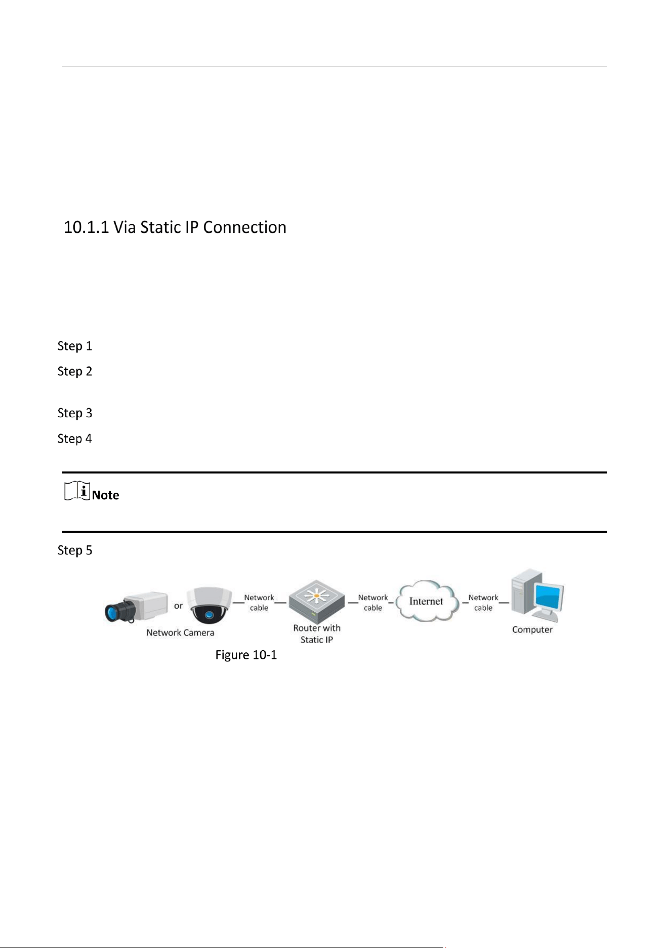
Connecting the network camera via a router
Connect the network camera to the router.
Assign a LAN IP address, the subnet mask and the gateway. Refer to Section 5.1.1 TCP/IP for
detailed IP address configuration of the network camera.
Save the static IP in the router.
Set port mapping, e.g., 80, 8000, and 554 ports. The steps for port mapping vary according to
the different routers. Please call the router manufacturer for assistance with port mapping.
Refer to Appendix 2 for detailed information about port mapping.
Visit the network camera through a web browser or the client software over the internet.
Accessing the Camera through Router with Static IP
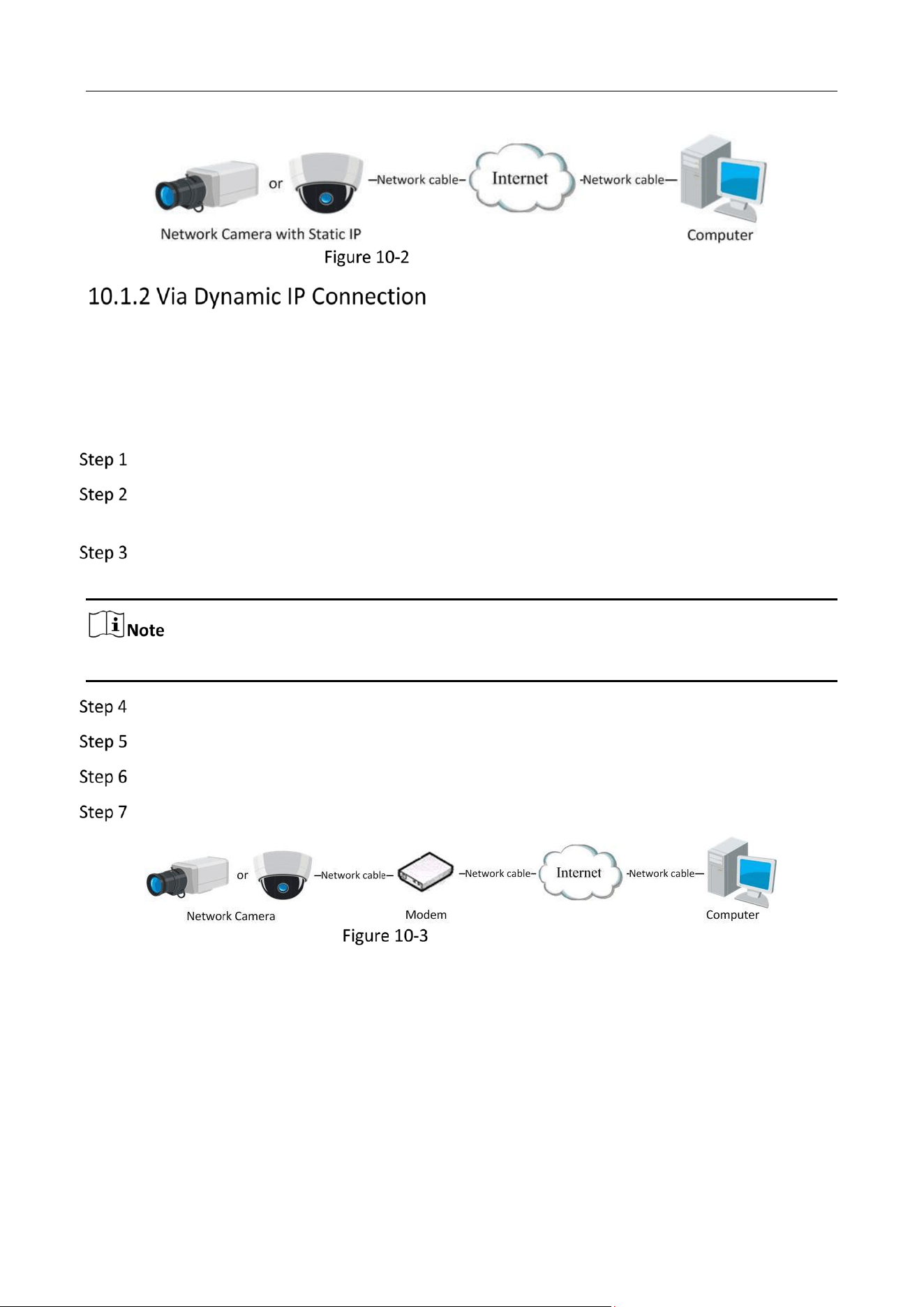
Connecting the network camera with static IP directly
You can also save the static IP in the camera and directly connect it to the internet without using a
router. Refer to Section 5.1.1 TCP/IP for detailed IP address configuration of the network camera.
Mobile Network Camera • User Manual
50
Accessing the Camera with Static IP Directly
Before you start:
Please apply a dynamic IP from an ISP. With the dynamic IP address, you can connect the network
camera to a modem or a router.
Connecting the network camera via a router
Connect the network camera to the router.
In the camera, assign a LAN IP address, the subnet mask and the gateway. Refer to Section
2.1.2 for detailed IP address configuration of the network camera.
Set port mapping. E.g. 80, 8000, and 554 ports. The steps for port mapping vary depending on
different routers. Please call the router manufacturer for assistance with port mapping.
Refer to Appendix 2 for detailed information about port mapping.
Apply a domain name from a domain name provider.
Configure the DDNS settings in the setting interface of the router.
Visit the camera via the applied domain name.
Connecting the network camera via a modem
Accessing the Camera with Dynamic IP
Mobile Network Camera • User Manual
51
Chapter 11 Appendix: SADP Software Introduction
Description of SADP
SADP (Search Active Devices Protocol) is a kind of user-friendly and installation-free online device
search tool. It searches the active online devices within your subnet and displays the information of
the devices. You can also modify the basic network information of the devices using this software.
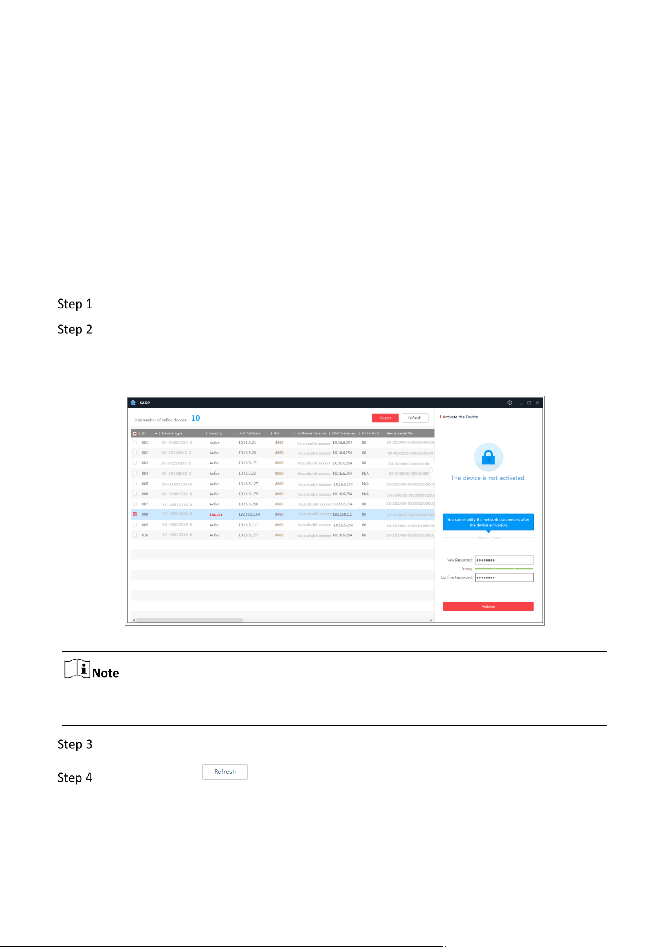
Search active devices online
Search online devices automatically
After launch the SADP software, it automatically searches the online devices every 15 seconds
from the subnet where your computer locates. It displays the total number and information
of the searched devices in the Online Devices interface. Device information including the
device type, IP address and port number, etc. will be displayed.
Figure A.1.1 Searching Online Devices
Device can be searched and displayed in the list in 15 seconds after it went online; it will be
removed from the list in 45 seconds after it went offline.
Search online devices manually
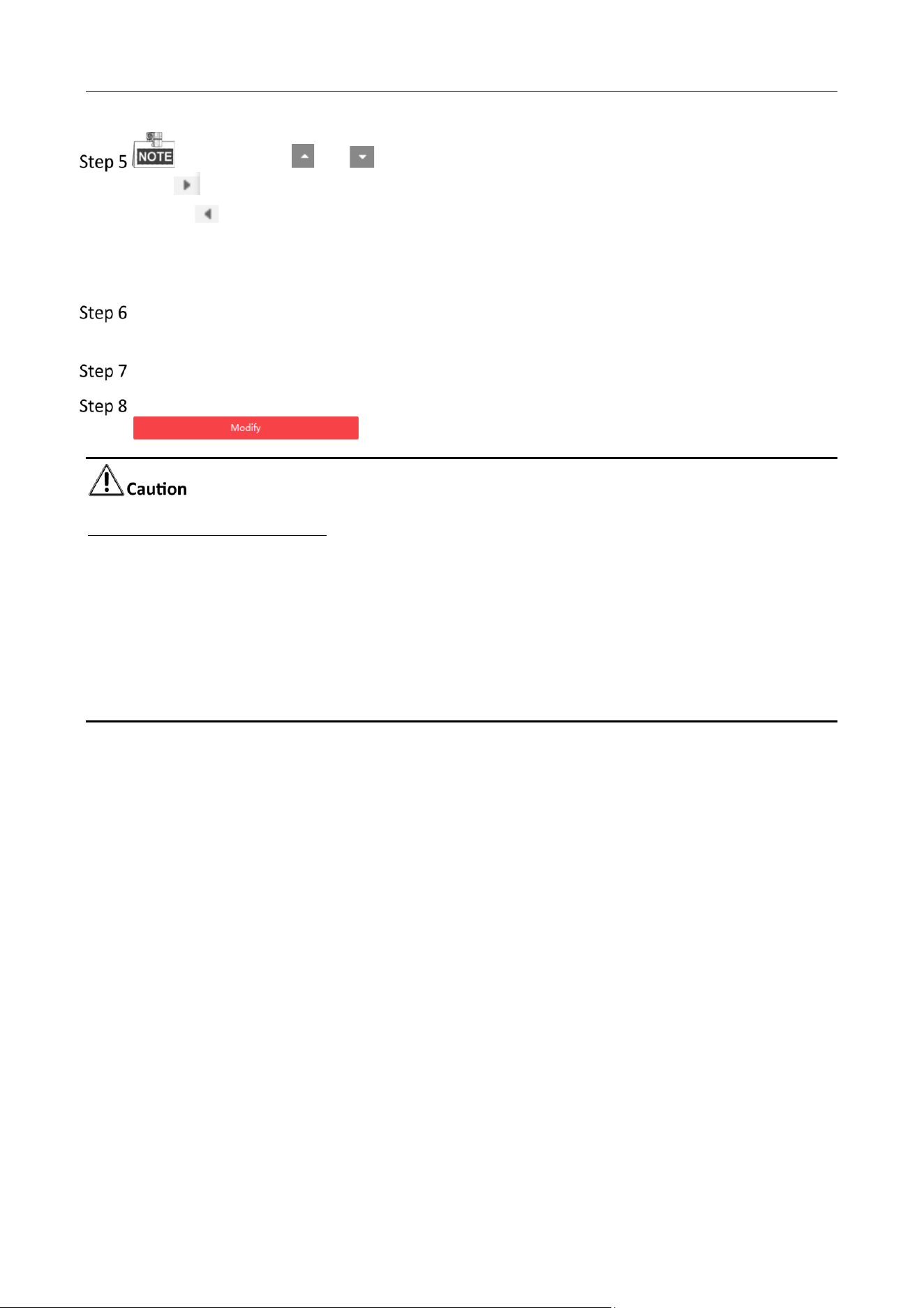
You can also click to refresh the online device list manually. The newly searched
devices will be added to the list.
Mobile Network Camera • User Manual
52
You can click or on each column heading to order the information; you can
click to expand the device table and hide the network parameter panel on the right side,
or click to show the network parameter panel.
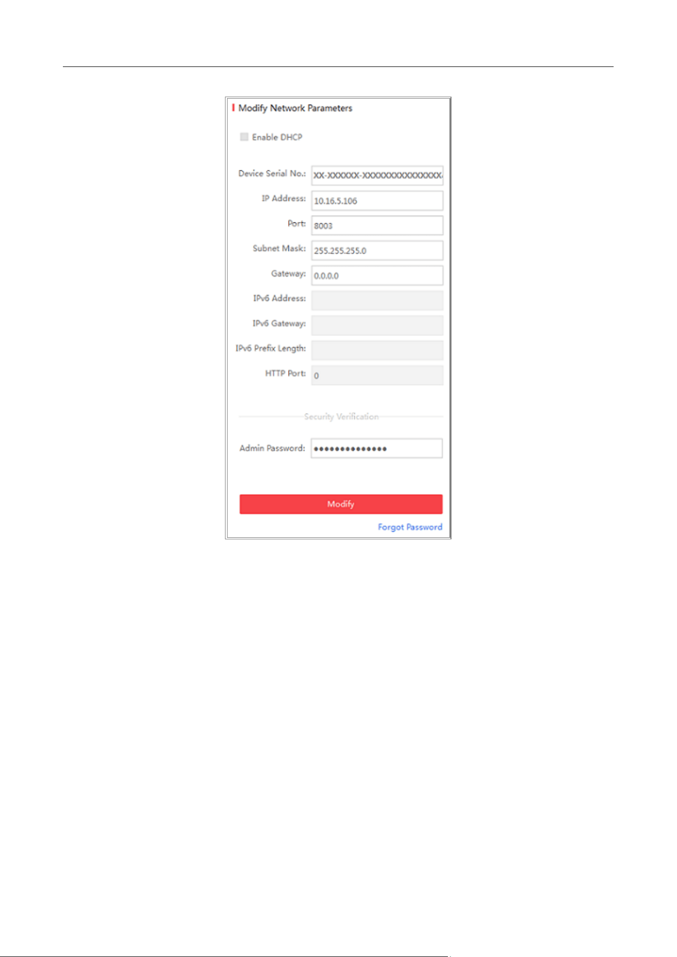
Modify network parameters
Select the device to be modified in the device list and the network parameters of the device
will be displayed in the Modify Network Parameters panel on the right side.
Edit the modifiable network parameters, e.g. IP address and port number.
Enter the password of the admin account of the device in the Admin Password field and click
to save the changes.
STRONG PASSWORD RECOMMENDED
We highly recommend you create a strong password of your own choosing (using a minimum
of 8 characters, including at least three of the following categories: upper case letters, lower
case letters, numbers, and special characters) in order to increase the security of your product.
And we recommend you reset your password regularly, especially in the high security system,
resetting the password monthly or weekly can better protect your product.
Proper configuration of all passwords and other security settings is the responsibility of the
installer and/or end-user.
Mobile Network Camera • User Manual
53
Figure A.1.2 Modify Network Parameters

0