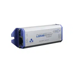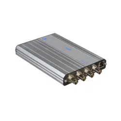

REAR CONNECTIONS & LEDS
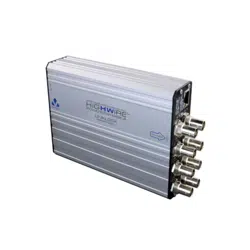
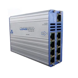
VLS-LS-B8
QUICK START GUIDE
8 PORT LONG RANGE ETHERNET & POE
LONGSPAN
BASE 8
05 0706
A B
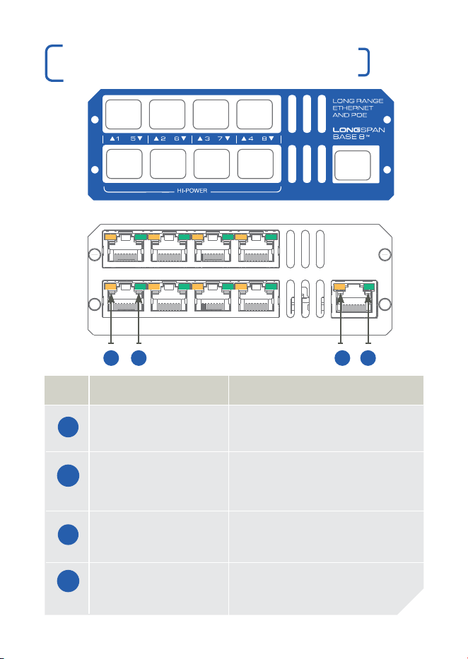
LED FUNCTION
LONGSPAN On = Link Established.
RJ45 Yellow Flash = Network Activity.
LONGSPAN On = 100Mbps.
RJ45 Green Flash = 10Mbps.
Blink = No Link to Camera.
Ethernet On = Link Established.
RJ45 Yellow Flash = Network Activity.
Ethernet On = Power Good.
RJ45 Green
C D
C
FRONT CONNECTIONS & LEDS
321 4
5
6
SURGE PROTECTION
Any LONGSPAN
®
network design for outdoor or external sections
must incorporate the appropriate level of surge protection to avoid
invalidation of warranty due to electrical storm damage. It is the
responsibility of the system installer to ensure the correct level of
surge protection. See also surge protection statement below and
LONGSPAN Application Notes.
IMPORTANT SAFET Y NOTES
| This equipment is designed for indoor use only. Place in a well
ventilated position.
| The LONGSPAN Base surface can get hot, so caution
should be taken when handling the unit. Please allow time
to cool after switching off before handling the surfaces.
| If equipment is used in a manner not specified by the manufacturer,
the protection provided by the equipment may be impaired.
Surge Protection
All Veracity products have been independently tested to verify their resilience to the stringent immunity levels of
international standards. Users should note that no electronic equipment can be guaranteed to be completely
protected at levels beyond the defined standard ; therefore product warranty cannot include damage to
products which has been caused by surges exceeding those of the standards specified, for example lightning
strike activity.
It is the user’s responsibility to implement relevant surge protection measures, as appropriate to the installation.
This may include the fitting of additional surge protection devices where required.
This Device Complies with Part 15 of the FCC Rules.
Operation is subject to the following two conditions: (1) this device may not cause harmful interference, and (2)
this device must accept any interference received, including interference that may cause undesired operation.
NOTE: This equipment has been tested and found to comply with the limits for a Class A digital device, pursuant
to Part 15 of the FCC Rules.
These limits are designed to provide reasonable protection against harmful interference when the equipment is
operated in a commercial environment. This equipment generates, uses, and can radiate radio frequency energy
and, if not installed and used in accordance with the instruction manual, may cause harmful interference to radio
communications. Operation of this equipment in a residential area is likely to cause harmful interference in which
case the user will be required to correct the interference at his own expense.
© Veracity UK Ltd 2020
QSG DV1.4EN LONGSPAN® &
SAFEVIEW® are registered trademarks
and LONGSPAN Base 8™ is a
trademark of Veracity UK Ltd
RoHS
D
A
B
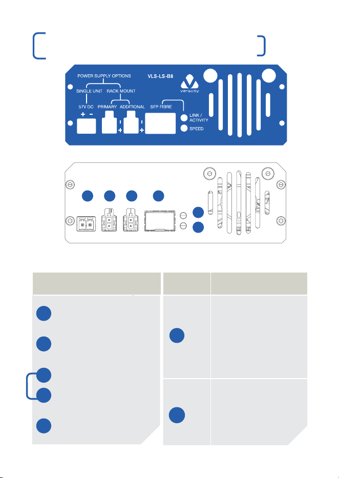
30W 30W 30W 30W
70W 70W 70W 70W
GigE
FRONT REAR
CONNECTIONS
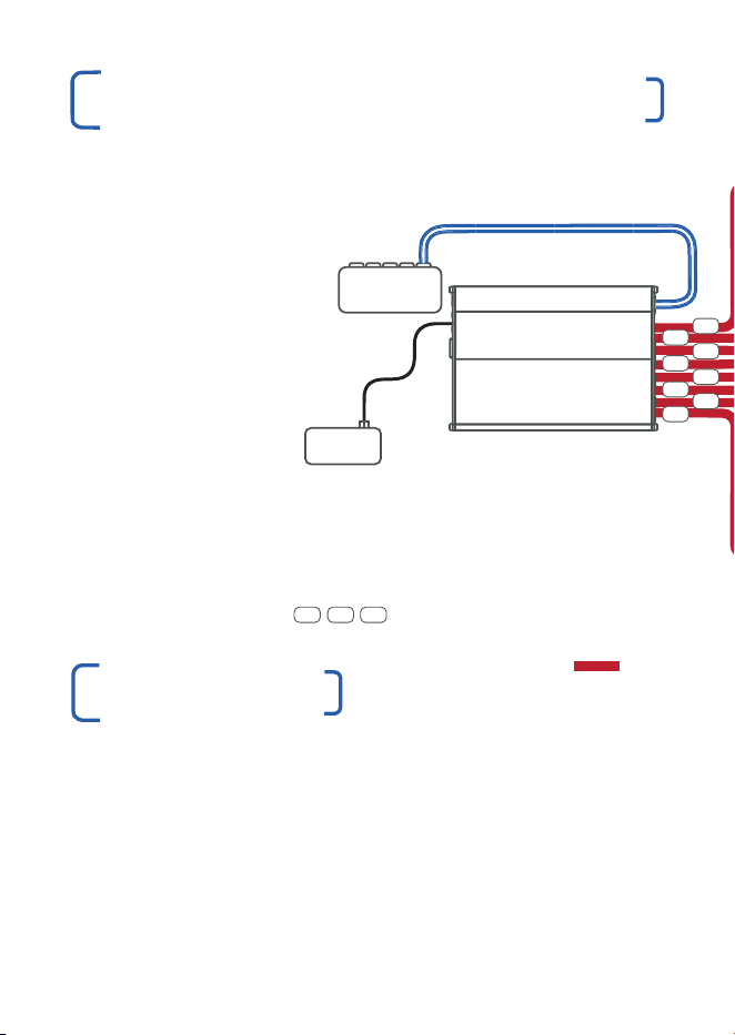
1 57V DC Single Unit
Power (up to 8 x 30W)
2 57V DC Primary Rackmount
Power (up to 8 x 30W)
2 57V DC Primary Rackmount
plus the 57V DC Additional
3 Rackmount Power
(up to 4 x 30W & 4 x 70W)
4 SFP Socket
SFP LED OPERATION
Top Link/Activity
Green = Power On.
5 Fibre detected.
Blinking Green = Link
is Established.
Network Activity.
Bottom Speed
Green = 1000Mbps.
6 Red = 10/100Mbps.
®

01 0302 04
OVERVIEW
LONGSPAN Base 8™ delivers unprecedented power and bandwidth
over extreme lengths of regular Cat5e or Cat6 network cable.
LONGSPAN Base 8 delivers unrestricted 100Base-TX over 8 ports.
The top 4 ports deliver 802.3at POE (up to 30W) and the bottom 4
ports deliver 802.3bt POE (up to 70W) at distances far beyond the
normal Ethernet limits for problem-free IP camera installation.
LONGSPAN Base 8 provides eight ethernet cable connections. The
Base unit has a single standard RJ45 Gigabit Ethernet port to allow
connection to a main network switch. An SFP socket is also provided
to allow a fibre network connection if required by the application.
All LONGSPAN Base 8 units must be powered through the DC power
connectors. The single-screw-terminal connector is designed for a
maximum of 6A at 57V DC. For lower-power applications Veracity’s
100W POE power supply (VPSU-POE-100) or 240W POE power
supply (VPSU-POE-240) may be used, connected to the single PSU
screw-terminal power connector.
For high-power applications (up to 30W per port for the top row
and up to 70W per port for the bottom row) a Veracity Rackmount
power supply must be used, connected to the Primary and Additional
power connectors. Each connector is designed for a maximum of 5A
at 57V DC. Both Primary and Additional connectors must be used for
maximum power delivery.
SAFET Y FEATURE
If the operating temperature of the LONGSPAN Base 8 unit becomes
too high (due to power overload, fan failure or obstructed airflow),
the output ports will shut down and the green LEDs will flash rapidly,
indicating a fault. This is to protect the internal electronics and is a
general safety feature.
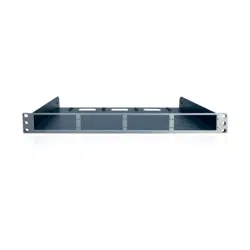
| Install the LONGSPAN Base 8 unit into the rack using the Veracity
Rackmount accessory (VRM-TRAY-BASE).
| Connect the Gigabit uplink port to the main network switch (alternatively
use an SFP module and connect that to the main network).
| At the IP camera (device) end, connect an IP camera (or other IP
device) to the Ethernet port of a LONGSPAN Camera, using the
recommended surge protection (item 3 in the diagram).
Repeat to install up to eight IP cameras (devices).
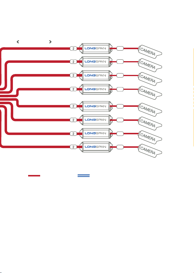
LONGSPAN APPLICATION DIAGRAM
| At the IP camera (device) end, connect the long network cables to
the extended network port of the LONGSPAN Camera units using
the recommended surge protection (item 2 in the diagram), noting
that CAT6 cable is recommended for cable runs longer than 300m
and essential for cable runs longer than 600m.
| At the base (switch) end, connect the other end of the long network
cables to the LONGSPAN Base 8 unit via the recommended surge
protection (item 1 in the diagram). For high-power applications,
note that the bottom row of RJ45 connectors can output up to
70W of POE, and the top row up to 30W of POE.
INSTALLATION
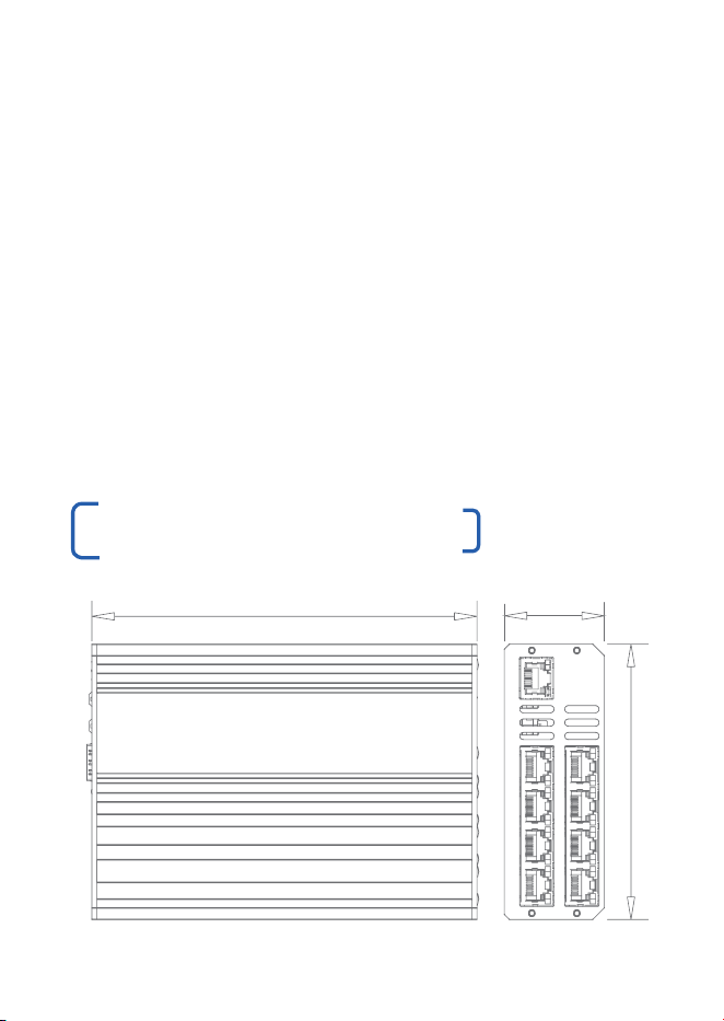
PRODUCT DIMENSIONS
| Install the appropriate power supply for the application, having
calculated the maximum power draw for the whole system, noting
that the LONGSPAN Base 8 unit itself will use 8W at idle and 20W
under maximum output load.
| Connect either a single unit power supply to the screw-terminal
connector or a Rackmount supply to the Primary and/or Additional
power connectors as appropriate for the total power required by
the application.
| Confirm 100Base-TX on the LEDs and confirm POE power availability
on the LONGSPAN Camera unit’s SAFEVIEW
®
LEDs and also that
each IP camera or other IP device is powered-up successfully.
| The installation is complete.
110 mm
40 mm
154 mm
GIGABIT ETHERNET DATA ONLY
VLS-LS-B8
VPSU-POE
POWER
ETHERNET & POE
GIGABIT ETHERNET DATA ONLY
LONGSPAN
BASE 8
POWER
SUPPLY
NETWORK
SWITCH
ADDITIONAL SURGE PROTECTION IS
RECOMMENDED FOR OUTDOOR RUNS
¨
VLS-1P-C
1 32
1
1
3
3
3
3
3
3
3
3
1
1
1
1
1
1
820M ON CAT6
ETHERNET & POE 100BASE-TX
LONGSPAN ETHERNET & POE
LONGSPAN ETHERNET & POE
01 0302 04
OVERVIEW
LONGSPAN Base 8™ delivers unprecedented power and bandwidth
over extreme lengths of regular Cat5e or Cat6 network cable.
LONGSPAN Base 8 delivers unrestricted 100Base-TX over 8 ports.
The top 4 ports deliver 802.3at POE (up to 30W) and the bottom 4
ports deliver 802.3bt POE (up to 70W) at distances far beyond the
normal Ethernet limits for problem-free IP camera installation.
LONGSPAN Base 8 provides eight ethernet cable connections. The
Base unit has a single standard RJ45 Gigabit Ethernet port to allow
connection to a main network switch. An SFP socket is also provided
to allow a fibre network connection if required by the application.
All LONGSPAN Base 8 units must be powered through the DC power
connectors. The single-screw-terminal connector is designed for a
maximum of 6A at 57V DC. For lower-power applications Veracity’s
100W POE power supply (VPSU-POE-100) or 240W POE power
supply (VPSU-POE-240) may be used, connected to the single PSU
screw-terminal power connector.
For high-power applications (up to 30W per port for the top row
and up to 70W per port for the bottom row) a Veracity Rackmount
power supply must be used, connected to the Primary and Additional
power connectors. Each connector is designed for a maximum of 5A
at 57V DC. Both Primary and Additional connectors must be used for
maximum power delivery.
SAFET Y FEATURE
If the operating temperature of the LONGSPAN Base 8 unit becomes
too high (due to power overload, fan failure or obstructed airflow),
the output ports will shut down and the green LEDs will flash rapidly,
indicating a fault. This is to protect the internal electronics and is a
general safety feature.
| Install the LONGSPAN Base 8 unit into the rack using the Veracity
Rackmount accessory (VRM-TRAY-BASE).
| Connect the Gigabit uplink port to the main network switch (alternatively
use an SFP module and connect that to the main network).
| At the IP camera (device) end, connect an IP camera (or other IP
device) to the Ethernet port of a LONGSPAN Camera, using the
recommended surge protection (item 3 in the diagram).
Repeat to install up to eight IP cameras (devices).
LONGSPAN APPLICATION DIAGRAM
| At the IP camera (device) end, connect the long network cables to
the extended network port of the LONGSPAN Camera units using
the recommended surge protection (item 2 in the diagram), noting
that CAT6 cable is recommended for cable runs longer than 300m
and essential for cable runs longer than 600m.
| At the base (switch) end, connect the other end of the long network
cables to the LONGSPAN Base 8 unit via the recommended surge
protection (item 1 in the diagram). For high-power applications,
note that the bottom row of RJ45 connectors can output up to
70W of POE, and the top row up to 30W of POE.
INSTALLATION
PRODUCT DIMENSIONS
| Install the appropriate power supply for the application, having
calculated the maximum power draw for the whole system, noting
that the LONGSPAN Base 8 unit itself will use 8W at idle and 20W
under maximum output load.
| Connect either a single unit power supply to the screw-terminal
connector or a Rackmount supply to the Primary and/or Additional
power connectors as appropriate for the total power required by
the application.
| Confirm 100Base-TX on the LEDs and confirm POE power availability
on the LONGSPAN Camera unit’s SAFEVIEW
®
LEDs and also that
each IP camera or other IP device is powered-up successfully.
| The installation is complete.
110 mm
40 mm
154 mm
GIGABIT ETHERNET DATA ONLY
VLS-LS-B8
VPSU-POE
POWER
ETHERNET & POE
GIGABIT ETHERNET DATA ONLY
LONGSPAN
BASE 8
POWER
SUPPLY
NETWORK
SWITCH
ADDITIONAL SURGE PROTECTION IS
RECOMMENDED FOR OUTDOOR RUNS
¨
VLS-1P-C
1 32
1
1
3
3
3
3
3
3
3
3
1
1
1
1
1
1
820M ON CAT6
ETHERNET & POE 100BASE-TX
LONGSPAN ETHERNET & POE
LONGSPAN ETHERNET & POE
REAR CONNECTIONS & LEDS
VLS-LS-B8
QUICK START GUIDE
8 PORT LONG RANGE ETHERNET & POE
LONGSPAN
BASE 8
05 0706
A B
LED FUNCTION
LONGSPAN On = Link Established.
RJ45 Yellow Flash = Network Activity.
LONGSPAN On = 100Mbps.
RJ45 Green Flash = 10Mbps.
Blink = No Link to Camera.
Ethernet On = Link Established.
RJ45 Yellow Flash = Network Activity.
Ethernet On = Power Good.
RJ45 Green
C D
C
FRONT CONNECTIONS & LEDS
321 4
5
6
SURGE PROTECTION
Any LONGSPAN
®
network design for outdoor or external sections
must incorporate the appropriate level of surge protection to avoid
invalidation of warranty due to electrical storm damage. It is the
responsibility of the system installer to ensure the correct level of
surge protection. See also surge protection statement below and
LONGSPAN Application Notes.
IMPORTANT SAFET Y NOTES
| This equipment is designed for indoor use only. Place in a well
ventilated position.
| The LONGSPAN Base surface can get hot, so caution
should be taken when handling the unit. Please allow time
to cool after switching off before handling the surfaces.
| If equipment is used in a manner not specified by the manufacturer,
the protection provided by the equipment may be impaired.
Surge Protection
All Veracity products have been independently tested to verify their resilience to the stringent immunity levels of
international standards. Users should note that no electronic equipment can be guaranteed to be completely
protected at levels beyond the defined standard ; therefore product warranty cannot include damage to
products which has been caused by surges exceeding those of the standards specified, for example lightning
strike activity.
It is the user’s responsibility to implement relevant surge protection measures, as appropriate to the installation.
This may include the fitting of additional surge protection devices where required.
This Device Complies with Part 15 of the FCC Rules.
Operation is subject to the following two conditions: (1) this device may not cause harmful interference, and (2)
this device must accept any interference received, including interference that may cause undesired operation.
NOTE: This equipment has been tested and found to comply with the limits for a Class A digital device, pursuant
to Part 15 of the FCC Rules.
These limits are designed to provide reasonable protection against harmful interference when the equipment is
operated in a commercial environment. This equipment generates, uses, and can radiate radio frequency energy
and, if not installed and used in accordance with the instruction manual, may cause harmful interference to radio
communications. Operation of this equipment in a residential area is likely to cause harmful interference in which
case the user will be required to correct the interference at his own expense.
© Veracity UK Ltd 2020
QSG DV1.4EN LONGSPAN® &
SAFEVIEW® are registered trademarks
and LONGSPAN Base 8™ is a
trademark of Veracity UK Ltd
RoHS
D
A
B
30W 30W 30W 30W
70W 70W 70W 70W
GigE
FRONT REAR
CONNECTIONS
1 57V DC Single Unit
Power (up to 8 x 30W)
2 57V DC Primary Rackmount
Power (up to 8 x 30W)
2 57V DC Primary Rackmount
plus the 57V DC Additional
3 Rackmount Power
(up to 4 x 30W & 4 x 70W)
4 SFP Socket
SFP LED OPERATION
Top Link/Activity
Green = Power On.
5 Fibre detected.
Blinking Green = Link
is Established.
Network Activity.
Bottom Speed
Green = 1000Mbps.
6 Red = 10/100Mbps.
®