Loading ...
Loading ...
Loading ...
9INSTALLATION
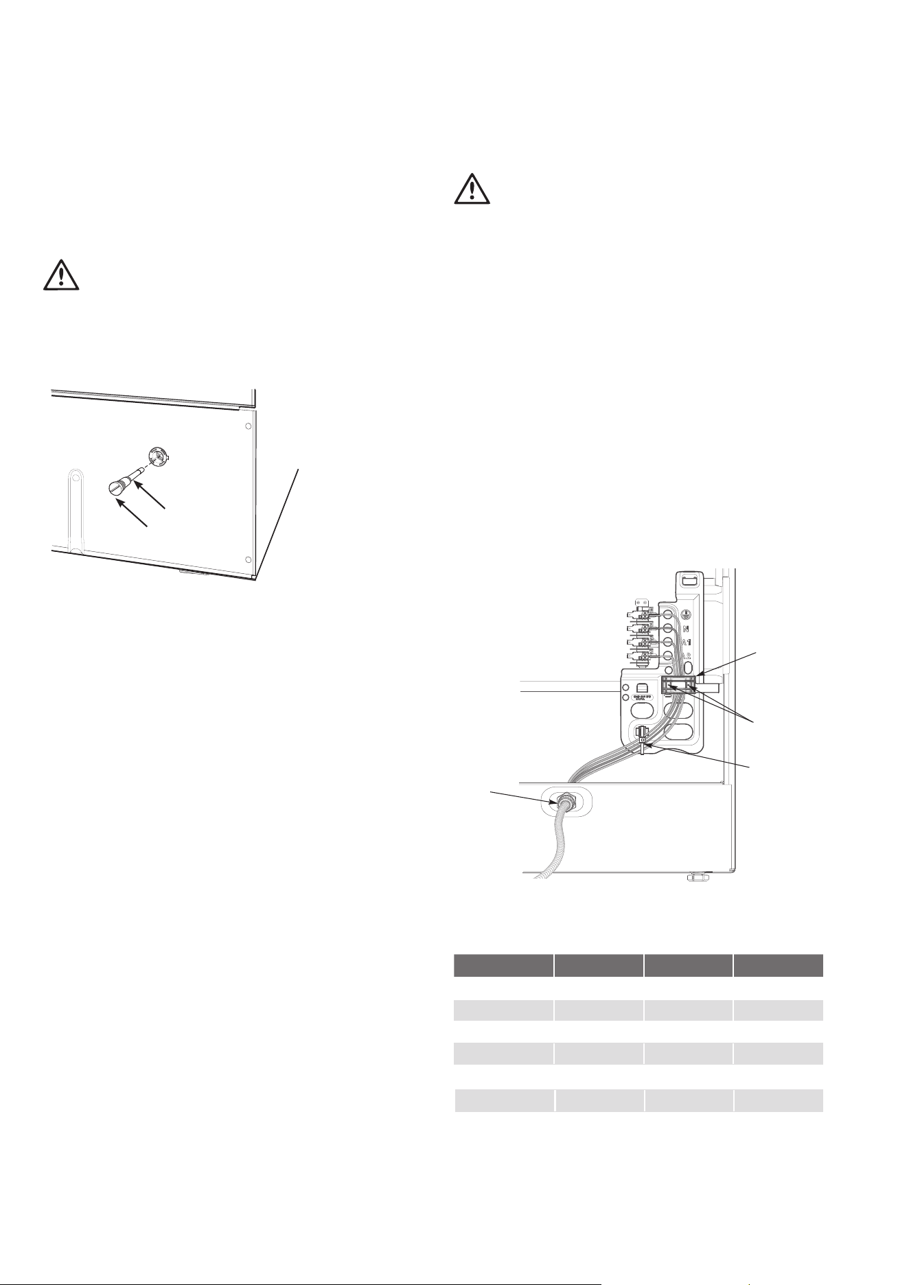
Service fuse location – Models with power point only
This product is fitted with a power outlet at each end of the
control panel. The outlets are protected by a replaceable 15
amp fuse located at the rear of the product.
WARNING
Before servicing the fuse, ensure that all power to the product
is switched off.
To access fuse, unscrew fuse housing and remove from
appliance. (See diagram).
Fuse
Fuse housing
Electric wiring requirements
The cooker MUST be installed in compliance with:
• Wiring connections in AS/NZS3000 wiring rules.
• Local regulations, municipal building codes and other
statutory regulations.
• Data plate – Gives information about the rating and
is located behind the bottom of the oven door.
For New Zealand only: The cooking range must be connected
to the supply by a supply cord fitted with the appropriately
rated plug that is compatible with the socket-outlet fitted
to the final sub-circuit in the fixed wiring that is intended to
supply this cooking range.
• A functional switch MUST be provided near the applianc
e
in an accessible position (AS/NZS3000 – Clause 4.7.1).
• Wiring MUST be protected against mechanical failure
(AS/NZS3000 – Clause 3.9).
• The cooker requires a means of all pole disconnection
incorporated into the fixed wiring. This MUST have a
disconnection gap of 3mm.
• The cooker MUST be properly earthed.
• Disconnection in the fixed wiring must occur in
accordance with the AS/NZS3000 Wiring Rules
• If the supply cord is damaged, it must be replaced by
the manufacturer, its service agent or similarly qualified
persons in order to avoid a hazard.
• This range must be connected with cable of 75°C
rating minimu
m.
• This product has passed the insulation resistance test after
manufacture. If the resistance reading is low at installation,
it is probably caused by moisture from the atmosphere
being absorbed by the elements after the range has been
produced. (Pass at 0.01MΩ AS/NZS 3000 Wiring Rules
Clause 8.3.6.2).
IMPORTANT
Before you cook in your new oven it is important that the
protective oils used in the manufacture of the product be
removed. Refer to ‘Before Operating your Appliance for the
First Time’ in the Using The Oven section.
Hard wiring
1. Remove rear panel.
2. Fit wires through hole at bottom centre using the
appropriate gland to protect insulation of wires from the
hole edge. Note that the secondary insulation of the wires
will probably need to be removed to fit through gland. If
the conduit to appliance is required to bend due to rear
wall an elbow may be required to achieve this.
3. Set the length of wiring from the gland to terminal block,
ensuring length is sufficient but not excessive.
4. Make connections to terminals and engage wires into
plastic clip. Cable tie as per diagram and secure plastic clip
with two long screws supplied.
5. Replace rear cover.
Cable tie
Plastic screw
securing points
Plastic clip
Gland
Rated power input
MODEL TOTAL kW A1 kW A2 kW
WLE524WC 10.0 4.2 5.8
WLE522WC 9.4 3.6 5.8
WLE530WCA 9.1 3.6 5.5
WLE543WC 9.7 4.1 5.6
WLE543WCB 9.9 4.1 5.8
WLE532WC 9.6 4.1 5.5
WLE522WC 9.9 4.1 5.8
Loading ...
Loading ...
Loading ...