Loading ...
Loading ...
Loading ...

7
10
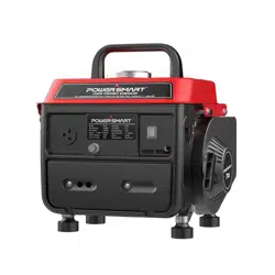
KNOWING YOUR GENERATOR
Use the illustrations below to become familiar with the locations and functions of the various components
and controls of this generator.
4 5 6 7 8 9
3
13
12
2
11
1
1
Air Cleaner – a removable,
cleanable, sponge-like element that
limits the amount of dirt pulled into
the engine.
8
DC Terminal
2
AC Circuit Rest Button – Reset
button that protects the generator
from AC outlet overload.
9
DC Circuit Reset Button – Reset button
that protects the generator from DC outlet
overload.
3
120 Volt AC Receptacle – To
connect electrical devices that run
on 120 Volt, 60 Hz, single phase,
AC current.
10
Ground Terminal – Connect grounding
wires here to properly ground unit.
4
Fuel Tank
11
Recoil Starter – Pull-cord for starting
engine.
5
Fuel Cap – Access to the fuel tank
for adding fuel.
12
Choke Lever – Adjusts the amount of air
let into then engine.
6
Carrying Handle – for easy
transport.
13
Fuel Valve
– Allows fuel to enter engine.
7
Engine Switch – Used to start/stop
engine.
Loading ...
Loading ...
Loading ...