
FOREWORD
Dear Customer,
Thank you for selecting your new Kia vehicle.
As a global car manufacturer focused on building high-quality vehicles with excep
-
tional value, Kia is dedicated to providing you with a customer service experience that
exceeds your expectations.
An authorized Kia dealership where factory-trained technicians and recommended
special tools are provided, can help if you need technical assistance.
This Owner's Manual will acquaint you with the operation of features and equipment
that are either standard or optional on this vehicle, along with the maintenance needs
of this vehicle. Therefore, you may find some descriptions and illustrations not appli
-
cable to your vehicle. You are advised to read this publication carefully and follow the
instructions and recommendations. Please always keep this manual in the vehicle for
your, and any subsequent owner's, reference.
All information contained in this Owner's Manual was accurate at the time of publica
-
tion. However, as Kia continues to make improvements to its products, the company
reserves the right to make changes to this manual or any of its vehicles at any time
without notice and without incurring any obligations.
Please drive safely, and enjoy your Kia vehicle!
© 2022 Kia Corporation
All rights reserved. May not be reproduced or translated in whole or in part without the written consent of Kia
Corporation.
Printed in Korea


How to use this manual
We want to help you get the greatest
possible driving pleasure from your
vehicle. Your Owner's Manual can assist
you in many ways.
We strongly recommend that you read
the entire manual. In order to minimize
the chance of death or injury, you must
read the WARNING and CAUTION sec
-
tions in the manual.
Illustrations complement the words in
this manual to best explain how to enjoy
your vehicle. By reading your manual,
you learn about features, important
safety information, and driving tips
under various road conditions.
The general layout of the manual is pro
-
vided in the Table of Contents. Use the
index when looking for a specific area or
subject, it has an alphabetical listing of
all information in your manual.
Chapters: This manual has nine chapters
plus an index. Each chapter begins with
a brief list of contents so you can tell at a
glance if that chapter has the informa
-
tion you want.
You will find various WARNINGS, CAU
-
TIONS, and NOTICES in this manual.
These WARNINGS were prepared to
enhance your personal safety. You
should carefully read and follow ALL
procedures and recommendations pro
-
vided in these WARNINGS, CAUTIONS
and NOTICES.
WARNING
A WARNING indicates a situation in
which harm, serious bodily injury or
death could result if the warning is
ignored.
CAUTION
A CAUTION indicates a situation in
which damage to your vehicle could
result if the caution is ignored.
NOTICE
A NOTICE indicates interesting or helpful
information is being provided.


Table of Contents
1
2
3
4
5
6
7
8
9
A
I
Introduction
Electric vehicle guide
Your vehicle at a glance
Safety features of your vehicle
Features of your vehicle
Driving your vehicle
What to do in an emergency
Maintenance
Specifications & Consumer information
Abbreviation
Index
Navigation QRG
Appendix


1Introduction
Introduction
Vehicle modifications.....................................................................1-2
Vehicle handling instructions .......................................................1-2

Introduction
21
Vehicle modifications
Introduction
Vehicle modifications
This vehicle should not be modified.
Modification of your vehicle could affect
its performance, safety or durability and
may even violate governmental safety
and emissions regulations.
NOTICE
Damage or performance problems
resulting from any modification may not
be covered under warranty.
CAUTION
Use of unauthorized electronic devices
may cause abnormal operation of the
vehicle, wire damage, battery discharge,
or fire. For your safety, do not use unau
-
thorized electronic devices.
Vehicle handling instructions
As with other vehicles of this type, failure
to operate this vehicle correctly may
result in loss of control, accident, or vehi
-
cle rollover.
Specific design characteristics (higher
ground clearance, track, etc.) give this
vehicle a higher center of gravity than
other types of vehicles. In other words, it
is not designed for cornering at the
same speeds as conventional 2-wheel-
drive vehicles.
Avoid sharp turns and abrupt maneu
-
vers. Again, failure to operate this vehi
-
cle correctly may result in loss of control,
accident, or vehicle rollover.
Be sure to read the "Reducing the risk of
a rollover" on page 6-194.

2Electric vehicle guide
Electric vehicle guide
Review of electric vehicle............................................................. 2-3
Main components of electric vehicle ..........................................2-4
僅 High Voltage (HV) battery (lithium-ion polymer) .............................. 2-4
僅 High voltage battery warmer system ..................................................... 2-5
EV menu..........................................................................................2-6
僅 EV mode screen.................................................................................................2-7
僅 Next departure.................................................................................................. 2-8
僅 Charging and climate..................................................................................... 2-8
僅 Vehicle to load (V2L)....................................................................................... 2-9
僅 Nearby stations................................................................................................2-13
僅 EV settings ........................................................................................................ 2-14
Charge types for electric vehicle............................................... 2-17
僅 Charging information....................................................................................2-17
僅 Charging time information .........................................................................2-17
僅 Charging types................................................................................................ 2-18
Charge indicator lamp for electric vehicle............................... 2-19
僅 Charging status................................................................................................2-19
Charging connector lock ............................................................ 2-19
僅 Locking charging cable ................................................................................2-19
僅 When the charging connector is locked ...............................................2-19
Scheduled charging ....................................................................2-20
Charging electric vehicle............................................................ 2-21
僅 Electric charging door...................................................................................2-21
Precautions for charging electric vehicle ................................ 2-22
僅 Unlock charging connector in emergency.......................................... 2-22
AC charge .....................................................................................2-24
僅 How to connect AC charger......................................................................2-24
僅 Checking charging status...........................................................................2-24
僅 How to disconnect AC charger ................................................................2-25

2 Electric vehicle guide
DC charge .....................................................................................2-26
僅 How to connect DC charger...................................................................... 2-26
僅 Checking charging status .......................................................................... 2-26
僅 How to disconnect DC charger................................................................ 2-27
Portable charge .......................................................................... 2-28
僅 Setting the charge level of the portable charger............................. 2-28
僅 How to connect portable charger
(ICCB: In-Cable Control Box).....................................................................2-30
僅 Checking charging status ...........................................................................2-31
僅 Charging status indicator lamp for portable charger.................... 2-32
僅 How to disconnect portable charger (ICCB: In-Cable Control
Box).......................................................................................................................2-34
僅 Precautions for portable charger (ICCB: In-Cable Control
Box).......................................................................................................................2-34
Charging the electric vehicle (Abrupt stop).............................2-35
Driving electric vehicle................................................................2-36
僅 Starting the vehicle .......................................................................................2-36
僅 Stopping the vehicle.....................................................................................2-36
僅 Virtual Engine Sound System (VESS)....................................................2-36
僅 Distance to empty..........................................................................................2-37
僅 ECO driving ......................................................................................................2-38
僅 Energy consumption ....................................................................................2-38
僅 Power/Charge gauge...................................................................................2-39
僅 State of charge (SOC) gauge for high voltage battery.................2-39
僅 Warning and indicator lights (related to electric vehicle) ........... 2-40
僅 LCD display messages..................................................................................2-41
Safety precautions for electric vehicle .................................... 2-46

3
2
2
Electric vehicle guide Review of electric vehicle
Electric vehicle guide
Review of electric vehicle
An electric vehicle is driven using a bat
-
tery and an electric motor. While general
vehicles use an internal combustion
engine and gasoline as fuel, electric
vehicles use electrical energy that is
charged & stored inside the high voltage
battery.
As a result, electric vehicles are eco-
friendly in that they do not require fuel
and do not emit exhaust gases.
Characteristics of electric vehi
-
cles
It is driven using the electrical energy
that is charged & stored inside the high
voltage battery. This method prevents
air pollution since fuel, like gasoline, is
not required, negating the emission of
exhaust gases.
A high performance electric motor is
used in the vehicle as well. Compared to
standard, internal combustion engine
vehicles, engine noise and vibrations are
much more minimal when driving.
When decelerating or driving downhill,
regenerative braking is utilized to charge
the high voltage battery. This minimizes
energy loss and increases the distance
to empty.
When the battery charge is not suffi
-
cient, AC charge (L2-Normal), DC charge
and Trickle charge (L1-Trickle) are avail
-
able. (Refer to "Charge types for electric
vehicle" on page 2-17.)
Battery information
The vehicle is composed of a high volt
-
age battery that drives the motor, air
conditioner, and charges an auxiliary
battery (12 V) that drives all other 12 V
systems.
The auxiliary battery is automatically
charged when the vehicle is in
READY
mode or the high voltage battery is
being charged.
NOTICE
What does regenerative braking do?
It uses the electric motor when deceler
-
ating and recaptures & transforms
kinetic to electrical energy in order to
charge the high voltage battery.

Electric vehicle guide
42
Main components of electric vehicle
Main components of electric
vehicle
僅
On-Board Charger (OBC)
: Trans
-
forms (inverts) AC power charge
power, to DC power, to charge the
high voltage battery
僅
Inverter
: Transforms direct current
into alternating current to supply
power to the motor, and transforms
alternating current into direct current
to charge the high voltage battery.
僅
LDC
: Transforms (converts) power
from the high voltage battery to low
voltage (12 V) to supply power to the
vehicle (DC-DC).
僅
VCU
: Functions as a supervisory con
-
troller of electric vehicle
僅
Motor
: Uses electrical energy stored
inside the high voltage battery to
drive the vehicle (functions like an
engine in a standard vehicle).
僅
Reduction gear
: Delivers rotational
force of the motor to the tires at
appropriate speeds and torque.
僅
High voltage battery (lithium-ion
polymer)
: Stores and supplies power
necessary for the electric vehicle to
operate (12 V auxiliary battery pro
-
vides power to the vehicle features
such as lights and wipers).
* OBC: On-Board Charger
* LDC: Low Voltage DC-DC Converter
* VCU: Vehicle Control Unit
High Voltage (HV) battery (lith
-
ium-ion polymer)
The HV battery powers the vehicle and
peripheral devices.
The charge amount of the HV battery
may gradually decrease when the vehi
-
cle is not driven or charged.
The battery capacity of the HV battery
may decrease over time when the vehi
-
cle is stored in high temperatures and
temporarily in low temperatures.
Distance to empty may vary depending
on the driving conditions (cargo, rain,
snow, wind, road surfaces), even if the
charge amount is the same. The HV bat
-
tery may expend more energy when
driving a fast pace or uphill. These
actions may reduce the distance to
empty.
The high voltage battery is used when
using the air conditioner/heater and/or
use the pre-conditioning prior to depar
-
tures. This may reduce the distance to
empty. Make sure to set moderate tem
-
peratures when using the air condi
-
tioner/heater.
Natural degradation may occur with the
high voltage battery depending on the
number of years the vehicle was used
and/or the number of charging cycles.
This will reduce the distance to empty
over time.
When the charge capacity and distance
to empty keep falling, contact an autho
-
rized Kia dealer/service partner for
inspection and maintenance.
If the vehicle will not be in use for an
extended period of time, charge the high
voltage battery once every three months
to prevent it from discharging. Also, if
the charge amount is not enough, imme
-
diately charge to full and store the vehi
-
cle.

5
2
2
Electric vehicle guide Main components of electric vehicle
AC (L2-Normal) charging is recom
-
mended to keep the high voltage battery
in optimal condition.
If the HV battery is only charged to 80%,
and you minimize the number of DC fast
charging, you can keep the HV battery
performance in optimal condition. (vs
charging the HV battery to 100% an/or
charging every drive cycle.)
The value of the high voltage battery
charge level may vary according to the
charging conditions (state of charger,
outside temperature, battery tempera
-
ture, etc.). In order to fully charge the
battery, the current of the high voltage
battery will be gradually decreased, so
that the longevity and safety of the bat
-
tery can be secured.
High voltage battery warmer sys
-
tem
The high voltage battery warmer system
prevents reduction of battery output
when battery temperature is low. If the
charging connector is connected, the
warmer system automatically operates
according to the battery temperature.
Charging time may shorten compare to
vehicles without the high voltage battery
warmer system. But, electricity charge
may increase because of high voltage
battery warmer system operation.
WARNING
僅 Do not remove or disassemble high
voltage components and high voltage
battery connectors and/or wiring
(orange cabling). Also, be careful not
to damage high voltage components
and the high voltage battery. It may
cause serious injury and significantly
impact the performance and durabil
-
ity of the vehicle.
僅 When inspection and maintenance is
required for high voltage components
and the high voltage battery, have the
vehicle inspected by an authorized
Kia dealer/service partner.
CAUTION
僅 Make sure to use a designated char
-
ger when charging the HV battery.
Using different types of chargers may
have a serious impact on vehicle
durability.
僅 Make sure that the HV battery charge
gauge does not reach E (Empty). If the
vehicle is kept at E (Empty) for a long
period, it may damage the high volt
-
age battery and the high voltage bat
-
tery may have to be replaced,
depending on the level of degrada
-
tion.
僅 If the vehicle is in a collision, contact
an authorized Kia dealer/service part
-
ner to inspect whether the high volt
-
age battery is still connected.
僅 If the vehicle is kept with insufficient
charge for a long period, it may dam
-
age the high voltage battery and the
high voltage battery may have to be
replaced depending on the level of
degradation.
僅 If the vehicle is in a collision, we rec
-
ommend to visit an authorized Kia
dealer/service partner to inspect
whether the high voltage battery is
still connected.
僅 Using the V2L function may reduce
the mileage due to the use of high
voltage battery energy, and repeated
use of the V2L function may cause a
decrease in the life of the high voltage
battery.
Electric vehicle guide
62
EV menu
NOTICE
The high voltage battery warmer system
operates when the charging connector is
connected to the vehicle.
However, the high voltage warmer sys
-
tem may not operate when battery tem
-
perature drops below -35 °C (-95 °F).
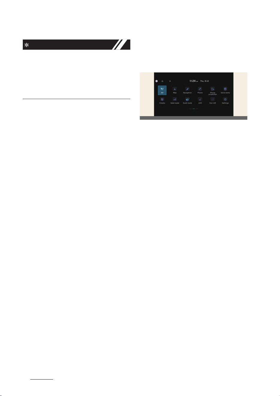
EV menu
If you select the
EV
menu at the multi
-
media system home screen, you can
enter
EV
menu.
* The image of
EV
menu screen in this
manual may differ from the actual
screen depending on the vehicle spec
-
ification and the version of the multi
-
media system software. For more
detailed information, please refer to
Navigation Quick Reference Guide.
OCV041277L
7
2
2
Electric vehicle guide EV menu
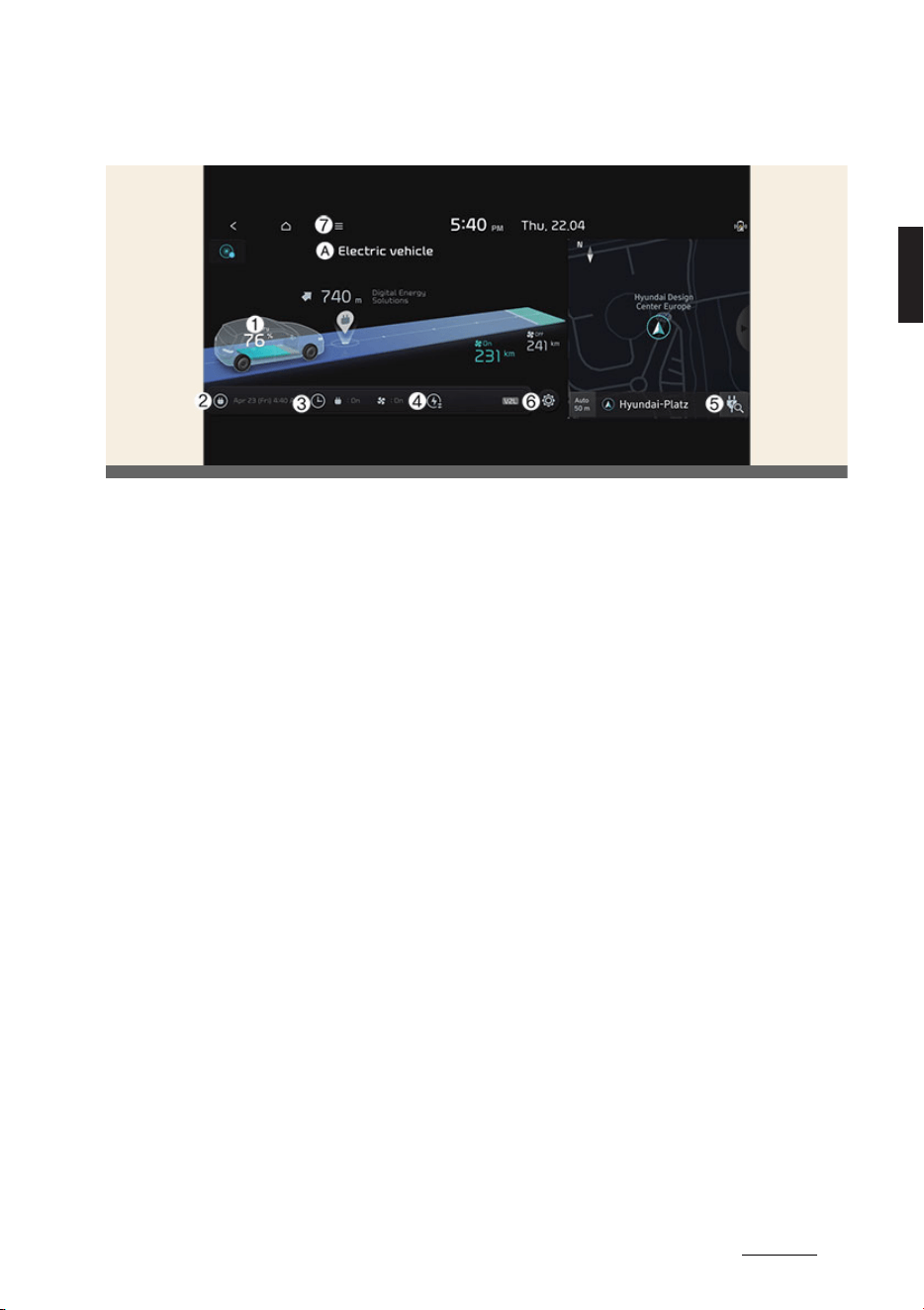
EV mode screen
A. Electric Vehicle
1
Energy Information
2
Next Departure
3
Charging and Climate
4
Vehicle to Load (V2L)
5
Nearby Stations
6
EV Settings
7
Menu
OCVEV041101L
Electric vehicle guide
82
EV menu
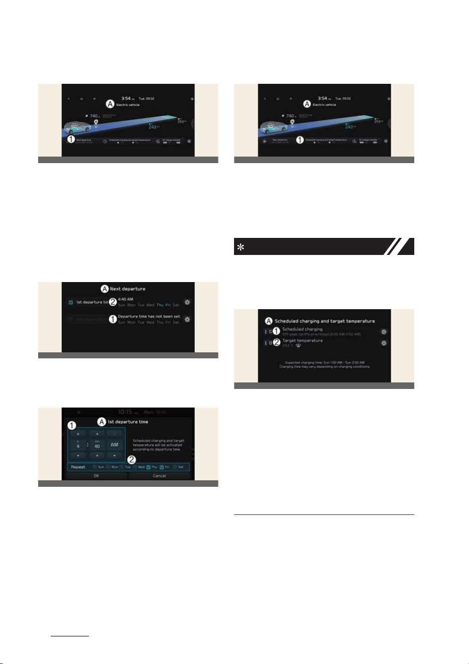
Next departure
A:
Electric vehicle
1 Next departure
Select
EV
→
Next departure
on the
screen. You can set the date and time of
when to charge the battery, climate con
-
trol temperature, and other various
functions.
Departure time
A:
Next departure
1 1st departure time
2 2nd departure time
A:
1st departure time
1
Departure Time
2
Departure Day
1. Set anticipated departure time for
scheduled charging and target tem
-
perature.
2. Select the day of the week to activate
scheduled charging and target tem
-
perature for departure time.
Charging and climate
A:
Electric Vehicle
1 Scheduled charging and target
temperature
Select
EV
→
Charging and Climate
on
the screen.
NOTICE
Vehicle must be connected with the
charging connector at the time pre-
scheduled time for the scheduled
charging.
A:
Scheduled charging and target
temperature
1 Scheduled Charging
2 Target Temperature
You can set the date and time of when
to charge the battery and the climate
control temperature. Also, you may
select the time to start charging using
the Off-peak time settings.
OCV041280L
OCV041281L
OCVGT042282L
OCV041283L
OCV041284L
9
2
2
Electric vehicle guide EV menu
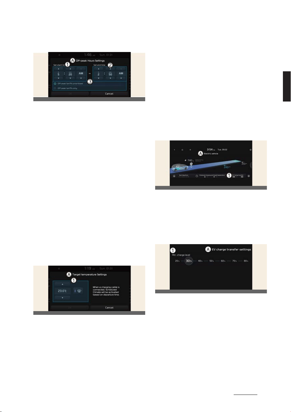
Off-peak time settings
A:
Off-peak time settings
1 Start Time
2 End Time
3
Charging options
1. If selected, starts charging only on the
designated off-peak time. If dese
-
lected, starts charging only on the
scheduled time.
2. Set the most inexpensive time to com
-
plete charging.
僅 Off-peak tariffs prioritised: If
selected, starts charging at off-
peak time (may keep on charging
pass off-peak time to charge
100%).
僅 Off-peak tariffs only: If selected,
charges only within off-peak time
(may not charge 100%).
Target temperature Settings
A:
Target temperature Settings
1
Target temperature
1. Set target temperature.
僅 If the target temperature (1) is set
with the cable connected, the cabin
temperature will be adjusted to the
target temperature at departure
time (without loss of high voltage
battery charging level). In cold
weather, pre-scheduled heating
helps enhance electric vehicle per
-
formance by heating the vehicle in
advance.
Vehicle to load (V2L)
V2L is the system that provides AC
power using the high voltage battery for
driving to operate several electronical
products.
For more details, refer to "Vehicle to load
(V2L)" on page 2-9.
A:
Electric Vehicle
1 EV Charge Transfer
Select
EV
→
V2L (Vehicle to load)
on
the screen.
You can set the battery discharging limit
for high voltage battery for driving.
A:
EV Charge Transfer Settings
1 Charge Level
If the vehicle reaches to the limit, it auto
-
matically cut supply of electricity.
OCV041285L
OCV041579L
OCV041287L
OCVGT042288L
Electric vehicle guide
102
EV menu
Energy information
Select
EV
and see the vehicle image
from the infotainment system screen.
You can check battery discharging level.
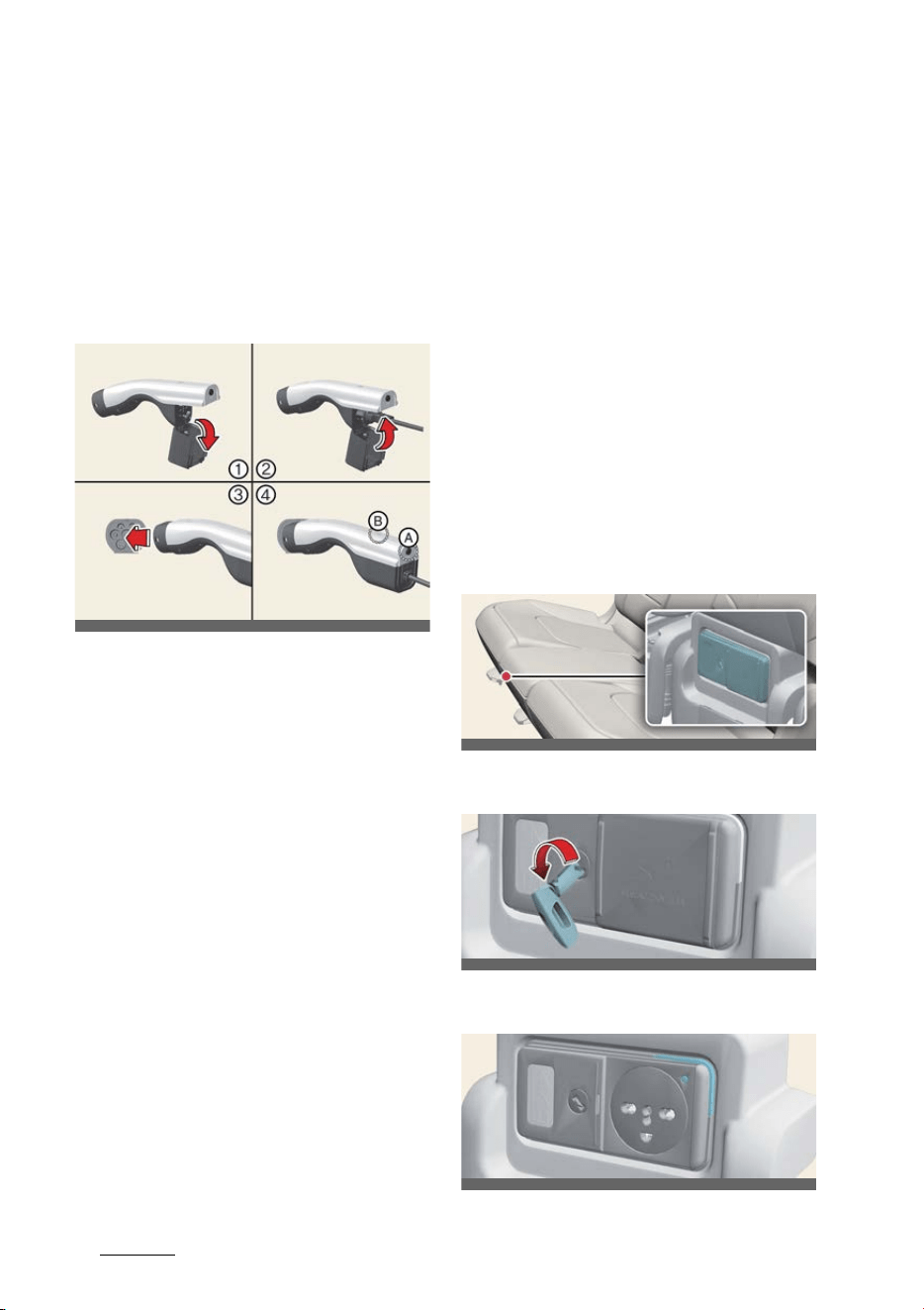
How to connect
Outdoor (if equipped)
1. Open the cover of the V2L connector.
2. Close the cover after connecting
home appliances and electronic prod
-
ucts to the power outlet.
3. Connect the V2L connector to the
charging hole on the vehicle.
4. Press the switch (A) of the V2L con
-
nector and check whether the light (B)
is on or off. The light (B) may not turn
on normally when:
僅 See the battery discharging limit for
high voltage battery for driving in
Energy consumption
menu on the
screen. If it is higher than the cur
-
rent amounts of high voltage bat
-
tery, the light (B) does not turn on.
僅 Check whether the light of V2L con
-
nector or indoor power outlet turns
on or not.
僅 If the warning message for V2L
appears on the cluster, refer to
"LCD display messages" on page 2-
11.
僅 If V2L does not operate previously
when you connects another home
appliances, we recommend to visit
an authorized Kia dealer/service
partner.
5. Press the switch (A) to turn off the
light (B) the V2L will be off. You can
disconnect the V2 connector when the
light (B) turns off or the charging door
lock is deactivated pressing the door
unlock button on the smart key.
Indoor (if equipped)
1. Connect to the power outlet located in
bottom of the rear seat with the EV
button in the ON position.
2. Use the mechanical key to unlock the
power outlet cover.
3. Check the operation status through
the front indicator of the power outlet.
OCVQ011001L_4
OCVQ011002L
OCVQ011046
OCVQ011047
11
2
2
Electric vehicle guide EV menu
僅Blue: Standby
僅 Red: No power supply even the
power outlet is connected
僅 Green: Normal power supply
through the normal connection of
the power outlet.
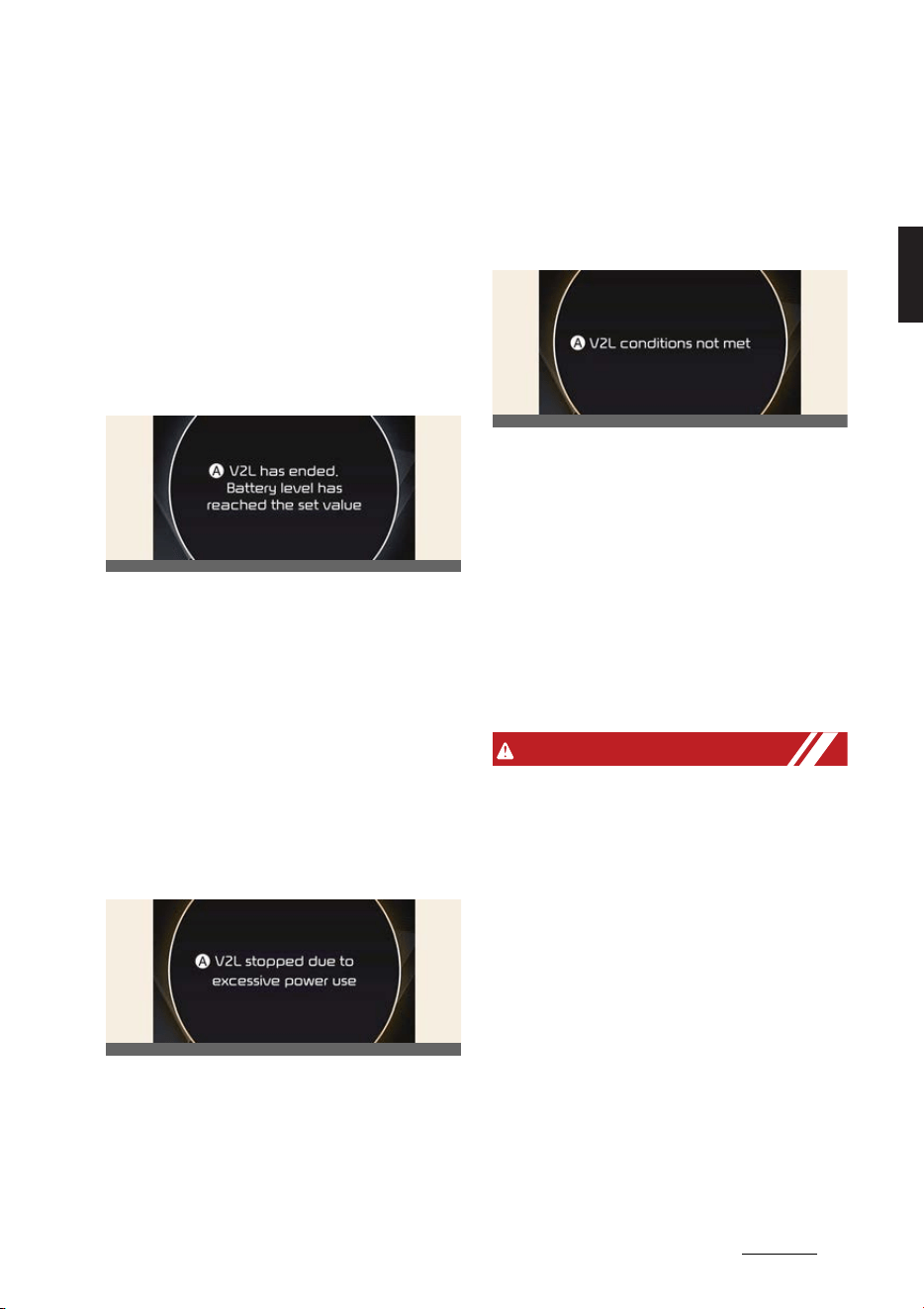
LCD display messages
V2L has ended. Battery level has
reached the set value
A:
V2L has ended. Battery level has
reached the set value
When the high voltage battery level
reaches the discharging limit set level,
the V2L will stop and the warning will be
displayed. If you want to use the V2L
continuously, make the discharging limit
set level lower than the present battery
level.
V2L stopped due to excessive
power use
A:
V2L stopped due to excessive
power use
If you use an electrical appliance that
exceeds the maximum power output the
vehicle can supply, it will stop working
and display a warning message. Make
sure that the total power consumption of
your electrical appliance exceeds the
V2L maximum power output.
V2L conditions not met
A:
V2L conditions not met
If V2L is interrupted for any of the fol
-
lowing reasons, a warning message is
displayed.
僅 V2L connector switch off
僅 V2L connector overheating
僅 Opening the charging door while
using the V2L indoor outlet
Make sure there are no problems with
the V2L connector and the vehicle
indoor outlet.
WARNING
僅 Do not touch the V2L connector of the
terminal of the vehicle charging hole.
僅 Do not put metal objects to the V2L
connector or charging hole. It might
be a cause of electric shock.
僅 Do not touch the V2L connector,
charging hole or power plug with a
wet hand. It might be a cause of elec
-
tric shock. Please handle with a dry
hand all the time.
僅 Confirm whether there is foreign sub
-
stance such as water or dust on the
V2L connector, charging hole or
power plug before connecting. If you
connect it with foreign substances, it
may be a cause of fire or electric
shock.
OCV041100L
OCV041101L
OCV041102L

Electric vehicle guide
122
EV menu
僅 Do not remodel or disassemble the
V2L connector. There is a risk of fire,
electric shock or injury.
僅 When the power plug is connected or
disconnected to the V2L connector or
open or close the connector cover of
the V2L, be careful not to be
scratched on the hand.
僅 Do not charge in the following condi
-
tions. The accident might occur.
- The V2L connector, charging hole,
power plug or cable is damaged,
corroded or rusted.
- The connection part is loose.
僅Do not use if the sheath of home
appliance cables is damaged or bro
-
ken. There is a risk of fire, electric
shock or injury.
僅 Never use an electric heating appli
-
ance like iron, coffee pot, and toaster
in the vehicle. It may cause a fire and
injury.
CAUTION
僅 Be well-informed of the manual to
prevent accidents.
僅 The V2L discharging mode is blocked
automatically in case of overheating.
(When the discharging mode is
blocked, check whether the V2L con
-
nector or power plug is contaminated,
worn, corroded or broken or the home
appliance capacity is over 16 A. If the
temperature falls to proper level after
it is left unattended, you can use it
again. Use proper home appliances.)
僅 Do not remodel or disassemble the
provided V2L connector. The failure
caused by remodeling or disassem
-
bling is not covered by the warrant.
僅 Do not drop the V2L connector or give
a strong impact to it.
僅 Do not place objects on the V2L con
-
nector.
僅 Be sure to disconnect the V2L connec
-
tor from the vehicle when you are fin
-
ished using V2L.
僅 When the high voltage battery charge
reaches the set discharging limit(%),
the operation stops, and a warning
message is displayed on the instru
-
ment cluster. If you want V2L opera
-
tion, set the discharging limit(%) lower
than the current battery charge.
僅 When using various electric products,
use them below the maximum power
capacity that can be supplied by the
vehicle.
僅 If you use an electrical appliance that
exceeds the maximum power capac
-
ity that the vehicle can supply, the
operation will stop and a warning
message will be displayed on the
instrument cluster. Make sure the
total power consumption of the elec
-
trical appliance you use does not
exceed the V2L maximum power
capacity.
僅 Some of the electric products may not
operate normally even if the product
has power consumption less than the
maximum power capacity provided
by the vehicle.
- Electrical products that require high
power during initial operation.
- Measuring devices that need to
process accurate data.
- Electric products sensitive to
inverter type AC power supply.
(Inverter: A device that converts DC
power into AC power)
僅 Do not use products that require a
continuous power supply, such as
medical equipment. The power supply

13
2
2
Electric vehicle guide EV menu
may be interrupted depending on the
vehicle's condition.
僅 Only use home appliances under 16
ampere.
僅 Put the power plug fully and use the
qualified plug that meets the stan
-
dard. If you use worn, corroded or
broken plug or improper plug, it might
be a cause of malfunction.
僅 Use the power plug with ground con
-
nection.
僅 Do not use high power home appli
-
ances such as air conditioner, washing
machine or dryer.
僅 Do not hang home appliances on to
the wire.
僅 For various devices connected to a
power outlet, use only products that
have obtained national safety certifi
-
cation. For usage and precautions,
refer to the manual of the device.
(Electrical appliances, multi-outlets,
cord extension cables, etc.)
僅 For electronic devices that are used
outdoors in a vehicle, use a product
with a waterproof function or use it in
a waterproof environment. Do not use
in environments with rain or high
humidity. (Electrical appliances, multi-
outlets, cord extension cables, etc.)
僅 If there is a risk of lightning, do not
use the V2L function outside the vehi
-
cle.
僅 Do not connect multiple portable
multi-outlets.
僅 When using an extension cable, if the
cable is twisted or overlapped by itself
may cause a fire. Be sure to use the
cable without twisting it.
僅 When using the vehicle's outdoor V2L
connector, power is also supplied to
the vehicle's indoor power outlet.
Unplug electrical appliances that are
not in use from the indoor power out
-
let.
僅 When using the V2L, the cooling fan in
the vehicle motor compartment can
operate automatically even if the
vehicle is turned off. Do not put your
hand near the cooling fan in the V2L
operating state.
NOTICE
僅 Please connect the V2L connector to
the charging hole within 60 seconds
after the charging cover opens. To
prevent theft after connecting, it is
changed to auto lock automatically so
that it is impossible to separate.
僅 When using V2L, cancel the scheduled
air conditioning setting. V2L may not
be available to operate if the sched
-
uled air conditioning is being acti
-
vated.
僅 V2L discharging mode will shut off if
the vehicle is turned off using indoor
V2L.
僅 Opening the charging door or con
-
necting the V2L connector to the
charging inlet, the V2L discharging
mode will shut off. If you want to use
the indoor and outdoor V2L simulta
-
neously, firstly connect the V2L con
-
nector to the charging inlet and use
the indoor V2L.
Nearby stations
A:
Electric Vehicle
OCV041289L
Electric vehicle guide
142
EV menu
Select
EV
and see the map from the
infotainment system screen. Stations
around the current location are
searched.
A:
Electric Vehicle
Select the icon on the screen.
A:
Near Current Position
Around the course, around the current
site, around the selected destination or
charging stations of interest will be
searched. If you choose the charging
station, the detailed information will be
provided.
For more detailed information, please
refer to Navigation Quick Reference
Guide.
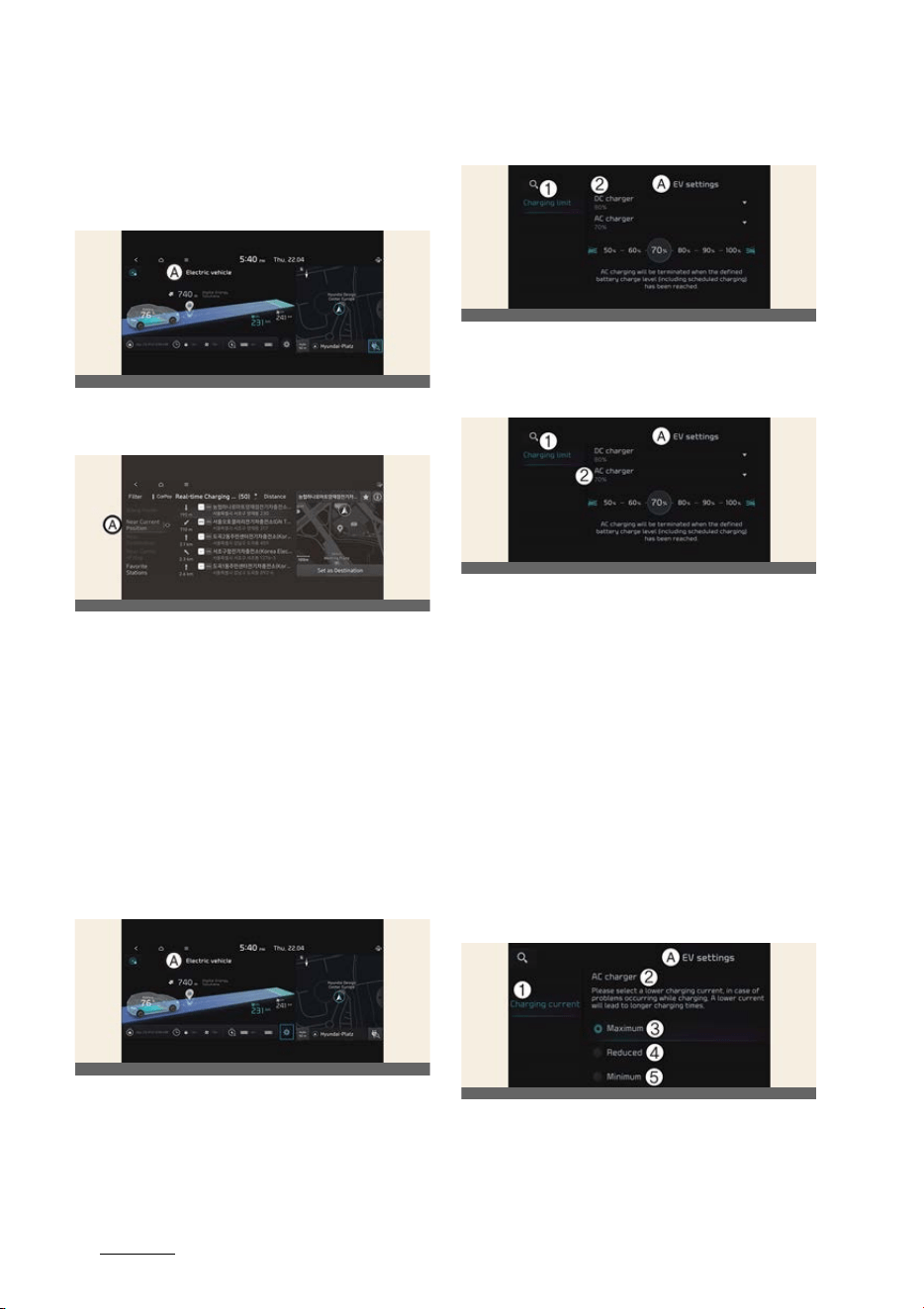
EV settings
A:
Electric Vehicle
Select the icon on the screen. You can
set the charging limit, charging current,
Battery conditioning mode and utility
mode functions.
Charging limit
A:
EV Settings
1 Charging limit
2 DC Charger
A:
EV Settings
1 Charging limit
2 AC Charger
僅 The target battery charge level can be
selected when charged with AC char
-
ger or DC charger.
僅 The charging level can be changed by
10%.
僅 If the target battery charge level is
lower than the high voltage battery
charge level, the battery will not be
charged.
Charging current
A:
EV Settings
1 Charging current
2 AC Charger
OCV041290L
OCV041291L
OCV041292L
OCV0GT42580L
OCV0GT42581L
OCVGT042295L

15
2
2
Electric vehicle guide EV menu
3 Maximum
4 Reduced
5 Minimum
僅 You can adjust the charging current
for an AC charger. Select an appropri
-
ate charging current.
僅 If the charging process does not start
or abruptly stops in the middle, rese
-
lect another proper current and re-try
charging the vehicle.
僅 Charging time varies depending on
which charging current is selected.
Utility mode
The high voltage battery is used instead
of the 12V auxiliary battery for operating
the convenient features of the vehicle.
When driving is not necessary such as
while camping or when stopping the
vehicle for a long time, it is possible to
use the electrical devices (audio, lights,
air conditioner, heater, etc.) for long
hours.
A:
EV Settings
1 Utility mode
2 Activate Utility Mode
System setting and activation
System setting
The driver can activate the Utility mode
function when the following conditions
are satisfied.
僅 The vehicle is in
READY
mode and
the gear is shifted to P (Park).
僅 The EPB (Electronic Parking Brake) is
not a malfunction.
僅
EV settings
→
Utility mode
is
selected on the infotainment system
screen.
System activation
When the system is activated:
僅The
READY
indicator will turn off, and
the
UTIL
indicator will illuminate on
the cluster and the EPB is applied.
僅 All electric devices are usable but the
vehicle cannot be driven.
僅 The EPB can be canceled by pressing
the EPB switch.
Gear cannot be shifted out of P (Park). If
a shift attempt is made,
Shifting condi
-
tions not met
message will be displayed
on the infotainment system screen.
System deactivation
The Utility mode can be deactivated by
pressing the EV button to the OFF posi
-
tion. The function cannot be deactivated
from the
EV settings
.
Battery conditioning mode (if
equipped)
A:
EV Settings
1 Battery conditioning mode
2 Battery conditioning mode
僅 The Battery conditioning mode is effi
-
cient during the winter time when the
high voltage battery temperature is
low. This mode is recommended to
OCVGT042297L
OSG2EVQ012060L

Electric vehicle guide
162
EV menu
improve driving and DC charging per
-
formances during winter. However,
the driving distance may be reduced
as the energy is required to increase
battery temperature.
僅 If the battery temperature is low
during driving, Battery conditioning
mode raises the battery temperature
to an adequate level. Also, if the bat
-
tery temperature is low when sched
-
uled air conditioner/heater is
activated, this mode is operated to
improve driving and charging perfor
-
mance. However, the mode is not
operated to ensure driving distance
when the battery level is low.
僅 If you set the DC charging station as a
destination in battery conditioning
mode, you can reduce the charging
time by raising the battery tempera
-
ture to an adequate level when you
arrive.
僅 Battery conditioning mode indicator
( ) light illuminates while battery
conditioning mode is operating.
NOTICE
僅 This mode is available for the vehicles
equipped with the battery heater.
僅 The infotainment system may change
after software updates. For more
information, refer to the manual pro
-
vided in the infotainment system and
the quick reference guide.
17
2
2
Electric vehicle guide Charge types for electric vehicle
Charge types for electric vehicle
Charging information
僅
AC Charge
: The electric vehicle is charged by plugging into a AC charger installed
at your home or a public charging station. (For further details, refer to "AC charge"
on page 2-24.)
僅
DC Charge
: You can charge at high speeds at public charging stations. Refer to
the respective company's manual that is provided for each DC charger type. Bat
-
tery performance and durability can deteriorate if the DC charger is used con
-
stantly.
Use of DC charge should be minimized in order to help prolong high voltage bat
-
tery life.
僅
Portable Charge
: The Electric vehicle can be charged by using household electric
-
ity. The electrical outlet at your home must comply with regulations and can safely
accommodate the Voltage/Current (Amps)/Power (Watts) ratings specified on the
portable charge.
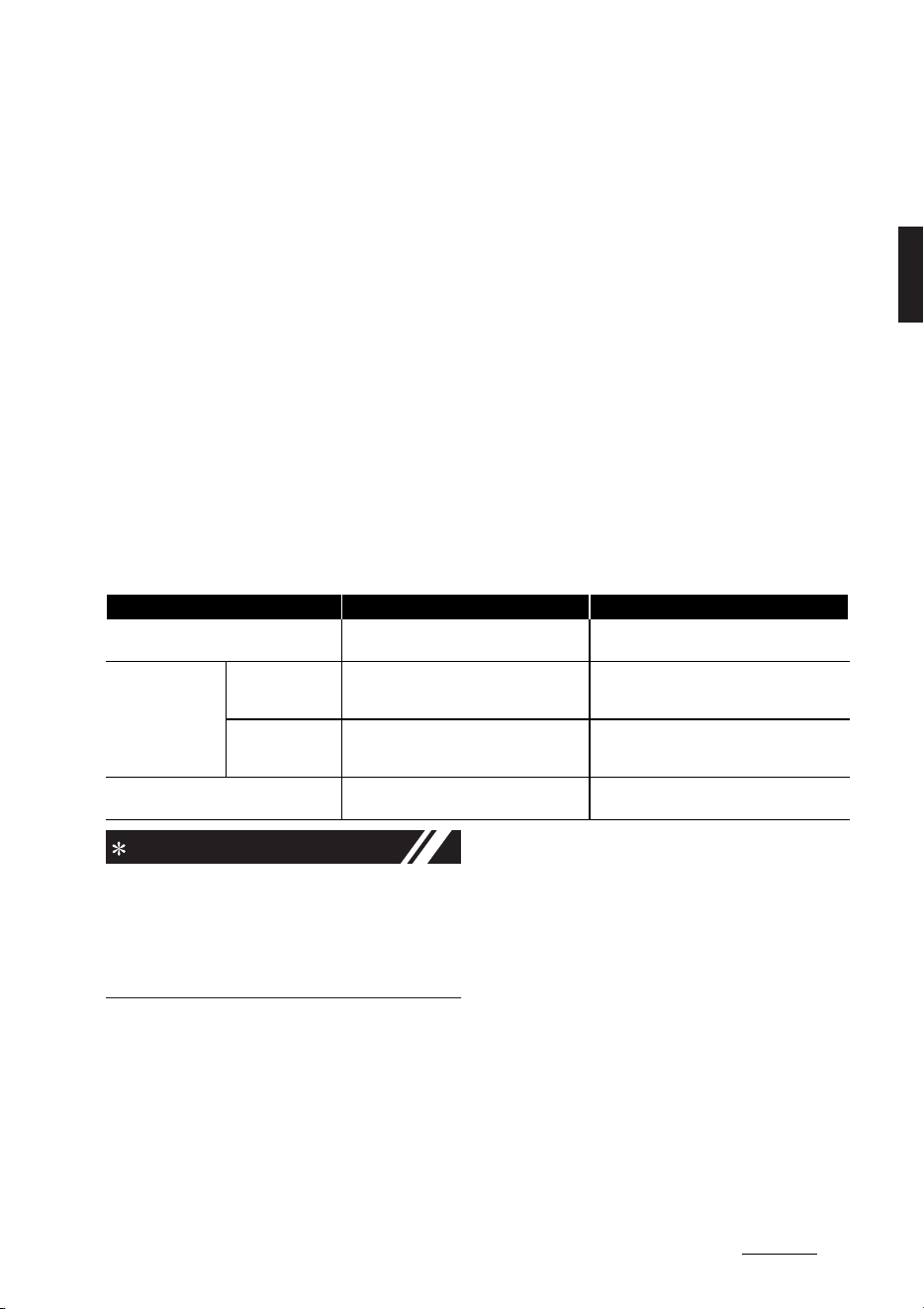
Charging time information
NOTICE
Depending on the condition and durabil
-
ity of the high voltage battery, charger
specifications, and ambient tempera
-
ture, the time required for charging the
high voltage battery may vary.
Charging type Standard battery type Extended battery type
AC charge
Takes approx. 9 hours at room tempera
-
ture when charged to 100%
Takes approx. 11 hours 45 minutes at room
temperature when charged to 100%.
DC charge
350 kW charger
Takes about 18 minutes at room tempera
-
ture when charged from 10% to 80%. Can
be charged to 100%.
Takes about 18 minutes at room tempera
-
ture when charged from 10% to 80%. Can be
charged to 100%.
50 kW charger
Takes about 63 minutes at room tempera
-
ture when charged from 10% to 80%. Can
be charged to 100%.
Takes about 73 minutes at room tempera
-
ture when charged from 10% to 80%. Can be
charged to 100%.
Portable charge
Takes approx. 25 hours at room tempera
-
ture when charged to 100%.
Takes approx. 33 hours at room temperature
when charged to 100%.
Electric vehicle guide
182
Charge types for electric vehicle
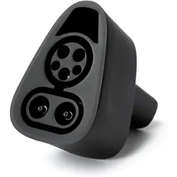
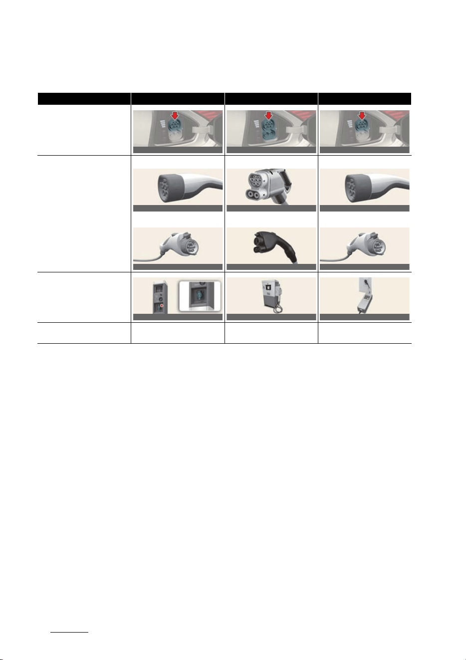
Charging types
僅 Actual charger image and charging method may vary in accordance with the char
-
ger manufacturer.
僅 A maximum diagnosis time of 3 minutes may be added to check the battery condi
-
tion during the battery charging process.
Category AC Charge DC Charge Portable Charge
Charging Inlet (Vehicle)
Charging Connector
Type A
Type B
Type A
Type B
Type A
Type B
Charging Outlet
How to Charge
Use AC charger installed at
home or public charging station
Use the DC charger at public
charging station
Use household current
OCVQ011003L
OCVQ011004L
OCVQ011003L
OCVQ011005L
ODEPVQ012039
OCVQ011006L
OCVQ011061
OCVQ011005L
ODEPVQ012039
OCVQ011007L
OCVQ011008L
OCVQ011009L
19
2
2
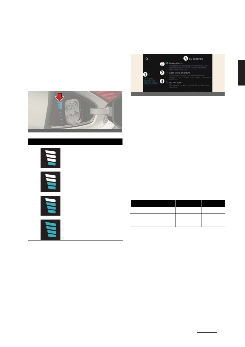
Electric vehicle guide Charge indicator lamp for electric vehicle
Charge indicator lamp for
electric vehicle
Charging status
When charging the high voltage battery,
the charge level can be checked from
outside the vehicle.
Electric charging door
Charging connector lock
Locking charging cable
A:
EV settings
1 Charging connector locking mode
2 Always lock
3 Lock while charging
4 Do not lock
You may select when the charging con
-
nector can be locked and unlocked in
the charging inlet.
Select
Settings
→
Vehicle
→
ECO Vehi
-
cle
→
Charging connector locking
mode
in the infotainment system.
When the charging connector is
locked
Always lock mode
The connector locks when the charging
connector is plugged into the charging
inlet. The connector is locked until all
doors are unlocked by the driver. This
mode can be used to prevent charging
cable theft.
僅 If the charging connector is unlocked
when all doors are unlocked, but the
charging cable is not disconnected
within 15 seconds, the connector will
be automatically locked again.
Lamp status Battery SOC [%]
0~24
25~49
50~74
75~100
OCVQ011010L
Category While charging Always
Before charging X O
While charging O O
Finished charging X O
OCVGT042582L
Electric vehicle guide
202
Scheduled charging
僅 If the charging connector is unlocked
when all doors are unlocked, but all
doors are locked again, immediately,
the connector will be automatically
locked again.
Lock while charging mode
The connector locks when charging
starts. The connector unlocks when
charging is complete. This mode can be
used when charging in a public charging
station.
Do not lock mode
The connector unlocks regardless of the
state of charging. Press the charging
connector release button, disconnect the
connector. Be careful to theft of the
charging cable.
Scheduled charging
You can set-up a charging schedule for
your vehicle using the Infotainment sys
-
tem or Kia Connect application. Refer to
Navigation Quick Reference Guide for
detailed information about setting
scheduled charging.
Scheduled charging can only be done
when using a AC charger or the portable
charger (ICCB: In-Cable Control Box).
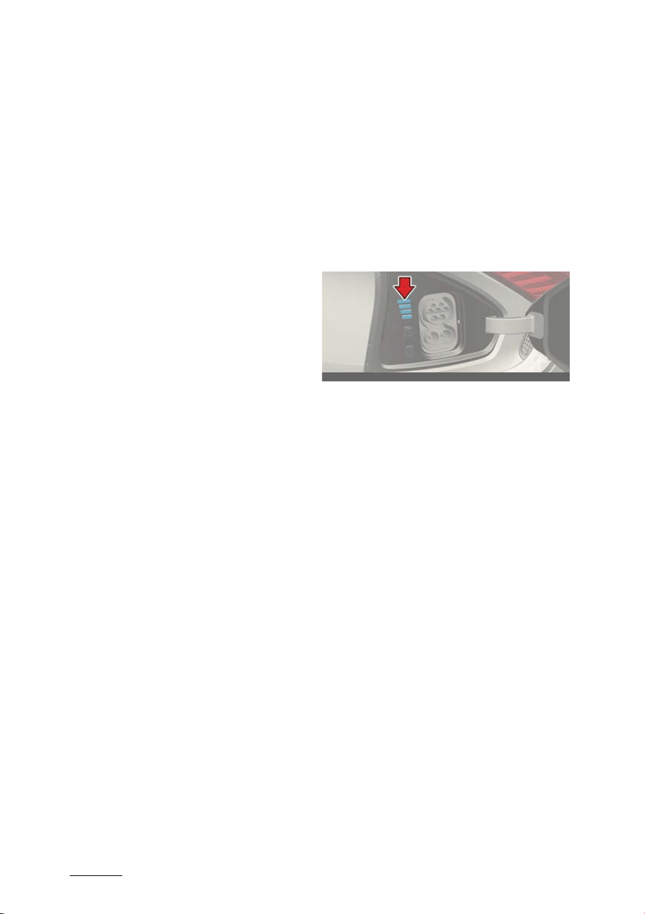
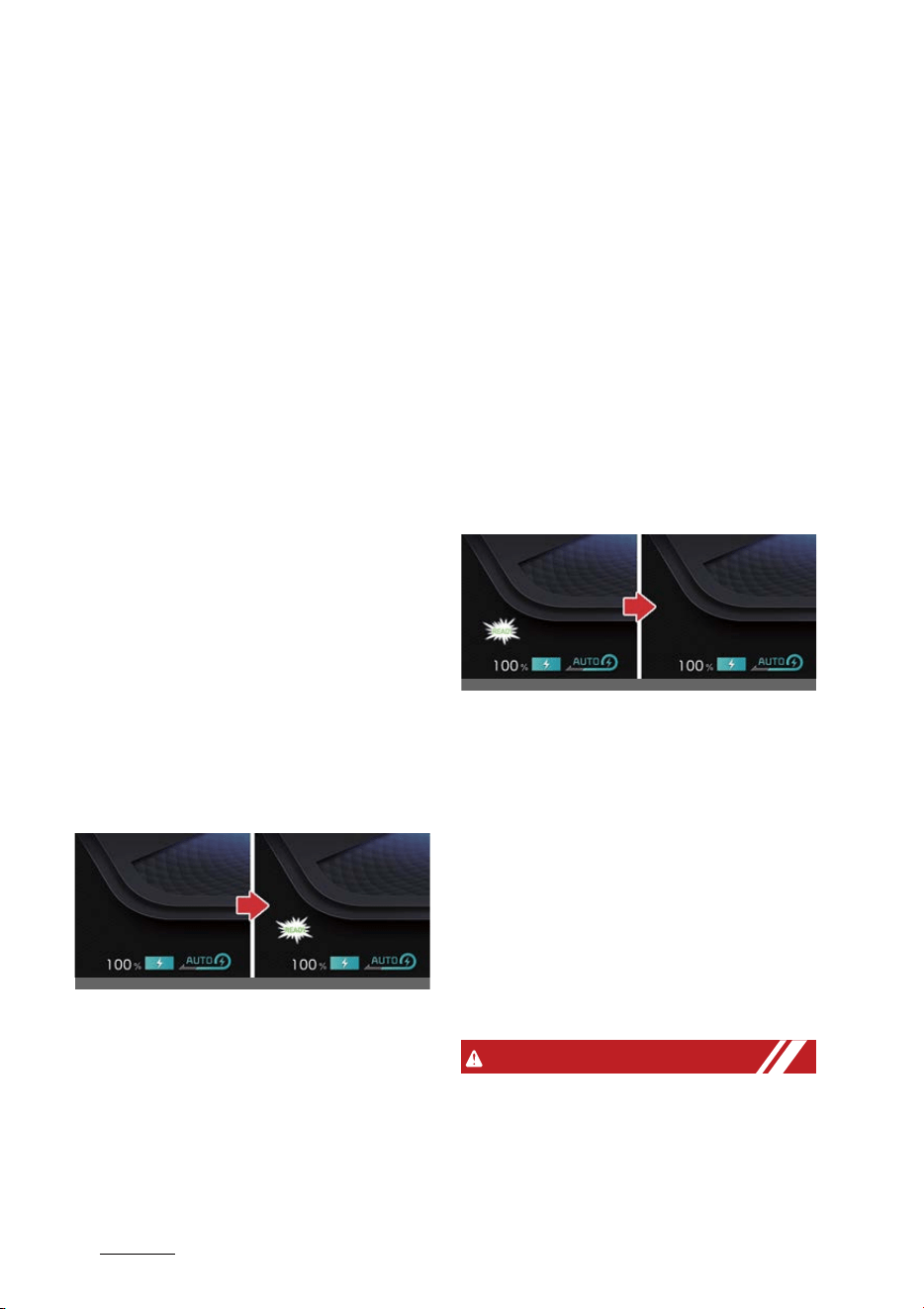
When scheduled charging is set and the
AC charger or the portable charger
(ICCB: In-Cable Control Box) is con
-
nected for charging, the indicator lamp
blinks from the first level to the last for
about 3 minutes to indicate that sched
-
uled charging is set.
When scheduled charging is set,
charging is not initiated immediately
when the AC charger or portable char
-
ger (ICCB: In-Cable Control Box) is con
-
nected. When immediate charging is
required, press and hold the charging
button on the charging door for 2 sec
-
onds or deactivate the scheduled charge
setting with the infotainment system or
Kia Connect application.
Refer to "AC charge" on page 2-24 or
"Portable charge" on page 2-28 for
details about connecting the AC charger
and the portable charger (ICCB: In-Cable
Control Box).
OCVQ011010L
21
2
2
Electric vehicle guide Charging electric vehicle
Charging electric vehicle
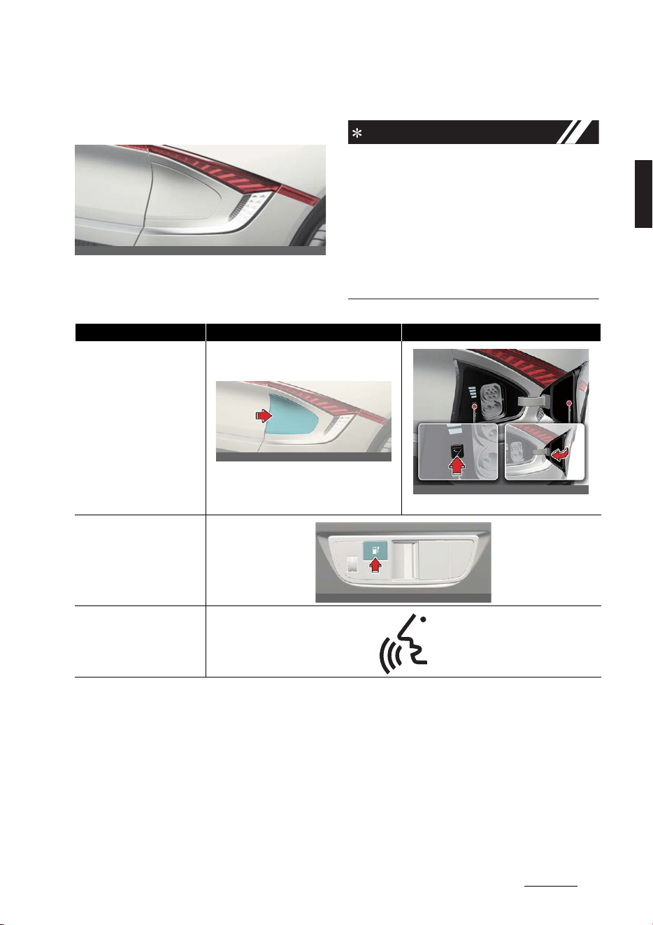
Electric charging door
The electric charge door will open and
close as follows.
NOTICE
The charging door automatically closes
when:
僅 The charge connector is disconnected
僅 The charging procedure has not done
for approximately 2 minutes while the
charging door is opened.
僅 The gear is in D (drive), N (neutral), or
R (Reverse).
OCVQ011011L
Methods Open Close
Push/Touch
Push the charging door.
Press the charging door close button.
Charging door open/close but
-
ton
Voice Recognition
OCVQ011012L
OCVQ011013L_2
OCVQ011014L
Electric vehicle guide
222
Precautions for charging electric vehicle
Precautions for charging elec
-
tric vehicle
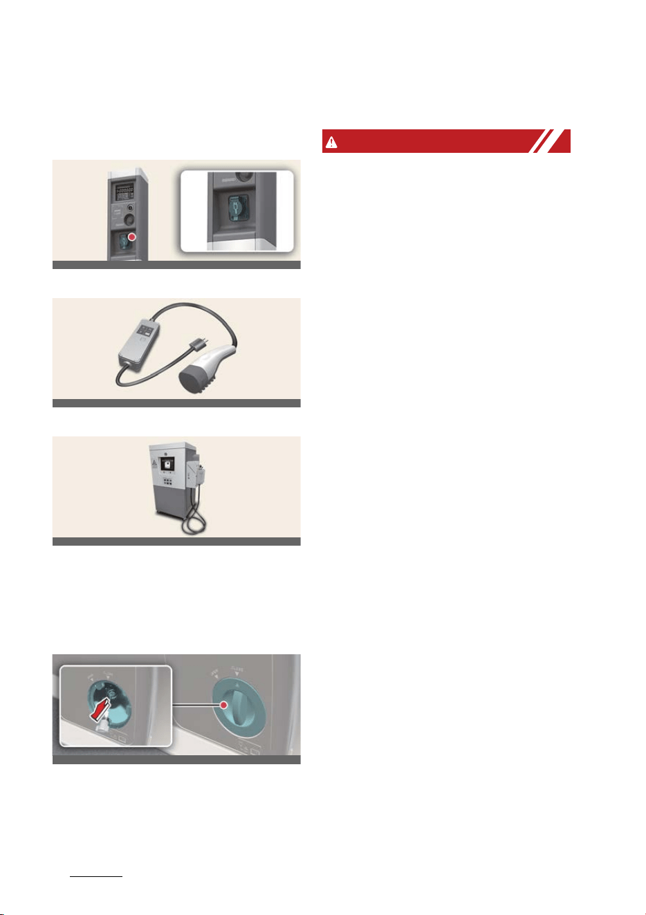
AC charger
AC charging cable (if equipped)
DC charger
* Actual charger image and charging
method may vary in accordance with
the charger manufacturer.
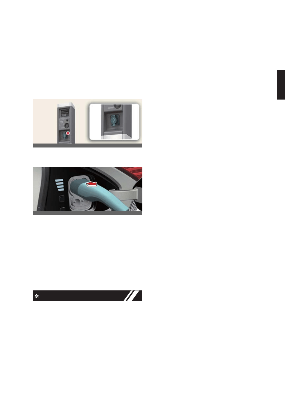
Unlock charging connector in
emergency
If the charging cable does not detach
due to battery discharge and failure of
the electric wires, open the tailgate and
slightly pull the emergency cable as
shown above. The charging connector
will then unlock.
WARNING
僅 Electromagnetic waves that are gen
-
erated from the charger can seriously
impact medical electric devices, such
as an implantable cardiac pacemaker.
When using electronic medical
devices, such as an implantable car
-
diac pacemaker, make sure to ask the
medical team and manufacturer
whether charging your electric vehicle
will impact the operation of the medi
-
cal electric devices, such as an
implantable cardiac pacemaker.
僅 Check to make sure there is no water
or dust on the charging cable connec
-
tor and plug before connecting to the
charger and charging inlet. Connect
-
ing while there is water or dust on the
charging cable connector and plug
may cause a fire or electric shock.
僅 Be careful not to touch the charging
connector, charging plug, and the
charging inlet when connecting the
charger connector cable to the
charging outlet and the charging inlet
on the vehicle.
僅 Comply with the following in order to
prevent electrical shock when
charging:
- Use a waterproof charger.
- Do not touch the charging connec
-
tor and charging plug with your
hands wet, or do not stand in water
or snow while connecting the
charging cable.
- Be careful when there is lightning.
- Be careful when the charging con
-
nector and plug are wet.
OCVQ011007L
OCVQ011032L
OCVQ011008L
OCVQ011018L

23
2
2
Electric vehicle guide Precautions for charging electric vehicle
僅 Immediately stop charging when you
discover abnormal symptoms (smell,
smoke, etc.).
僅 Replace the charging cable if the
cable coating is damaged to prevent
electrical shock.
僅 When connecting or removing the
charging cable, make sure to hold the
charging connector handle.
僅 Only use the charging cable (if
equipped) certified by Kia. If you use a
separate extension cable such as a
reel or use an uncertified cable, it may
cause abnormalities of electrical out
-
lets, leading to fire or explosion.
僅 If you pull the cable itself (without
using the handle), the internal wires
may be disconnected or get dam
-
aged. This may lead to electric shock
or fire.
僅 Do not leave the vehicle with the
charging door open. An open
charging door may indicate that the
vehicle door has been unlocked and
may be subject to vehicle theft.
CAUTION
僅 Always keep the charging connector
and charging plug in clean and dry
condition. Be sure to keep the
charging cable in a condition where
there is no water or moisture.
僅 Make sure to use the designated
charger for charging the electric vehi
-
cle. Using any other charger may
cause failure.
僅 Before charging the battery, turn the
vehicle [OFF].
僅 When the vehicle is switched [OFF]
while charging, the cooling fan inside
the motor compartment may auto
-
matically operate. Do not touch the
cooling fan while charging.
僅 Be careful not to drop the charging
connector. The charging connector
can be damaged.
僅 Do NOT use a extension cord, when
using the L1-Trickle charger, as this
may overheat and/or cause damage.
NOTICE
When charging or right after charging
the high voltage battery, the cooling will
be made using air conditioner system in
order to control the high voltage battery
temperature.
At this time, the noise might occur by the
air conditioner compressor and cooling
fan, but this is due to normal operation.
Electric vehicle guide
242
AC charge
AC charge
* Actual charger image and charging
method may vary in accordance with
the charger manufacturer.
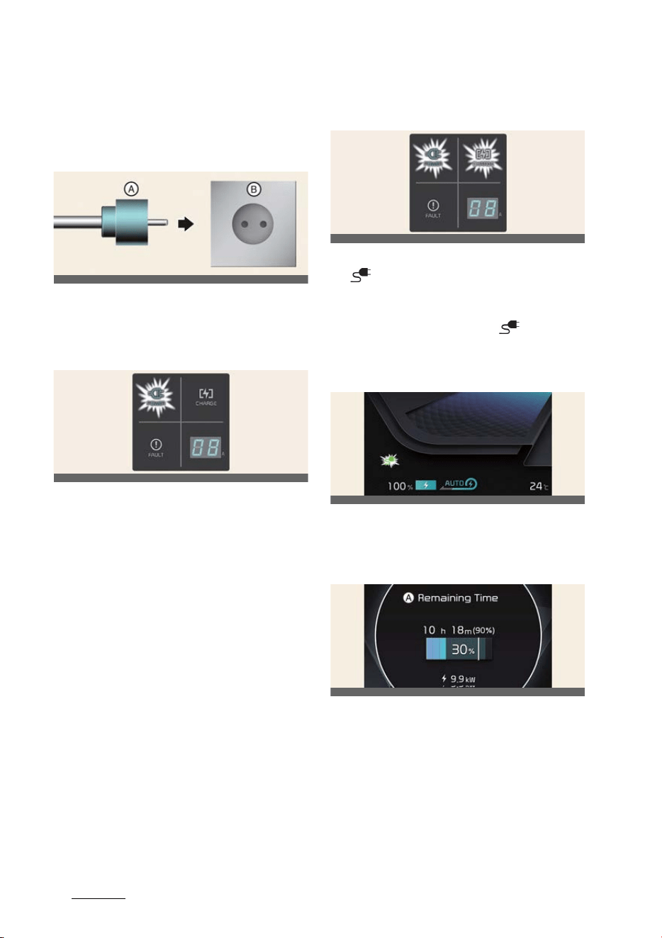
How to connect AC charger
1. Depress the brake pedal and apply
the parking brake.
2. Turn OFF all switches, shift to P
(Park), and turn OFF the vehicle. If
charging is initiated without the gear
in P (Park), the charging will start after
the gear is automatically shifted to P
(Park).
3. Open the charging door.
For more details, refer to
"Electric
charging door" on page 2-21
.
4. Check if there is dust on the charging
connector and charging inlet.
5. Hold the charging connector handle
and connect it to the vehicle charging
inlet. Push the connector all the way
in. If the charging connector and
charging terminal are not connected
properly, this may cause a fire.
For more details, refer to
"Locking
charging cable" on page 2-19
.
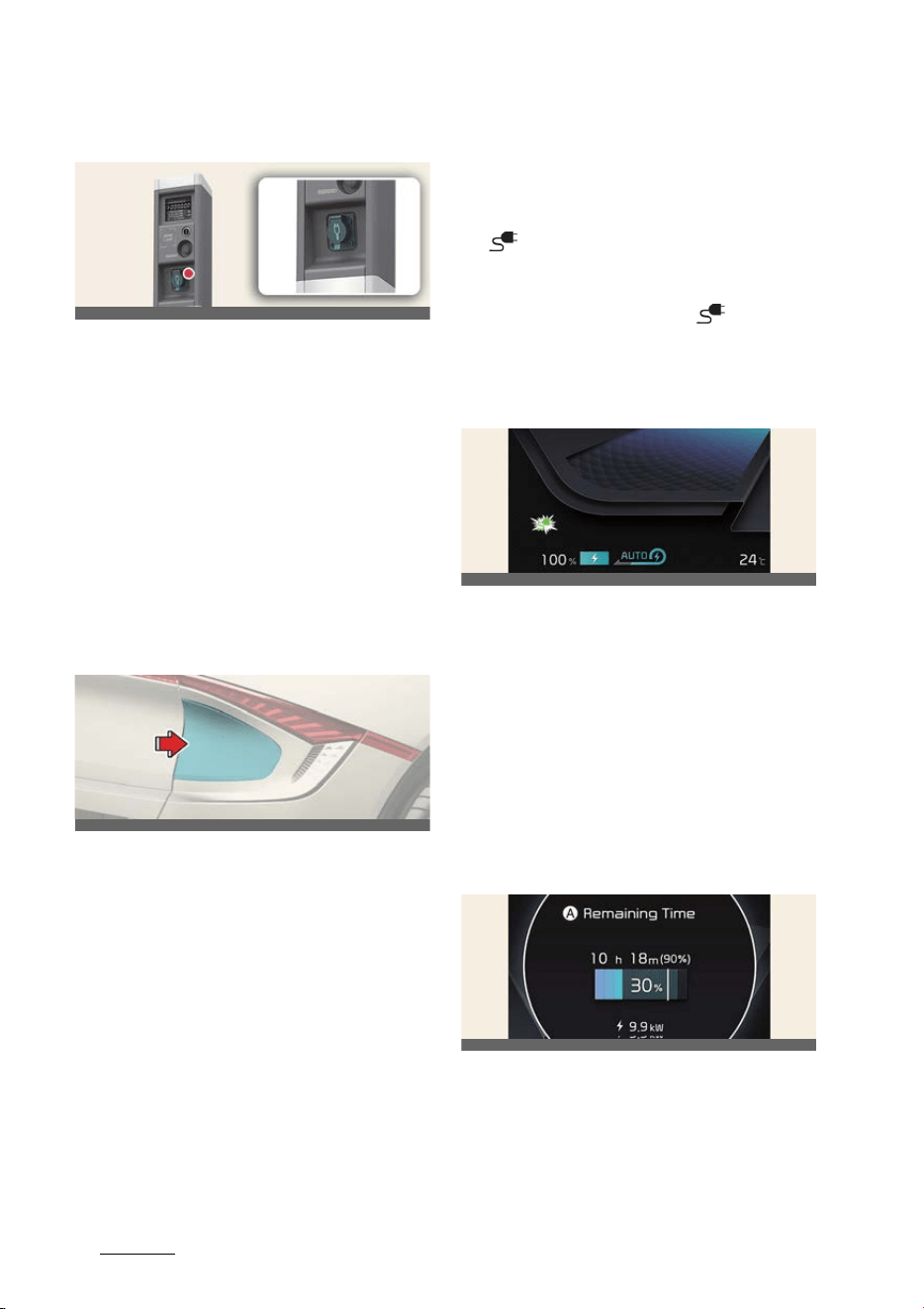
6. Connect the charging plug to the elec
-
tric outlet at a AC charging station to
start charging.
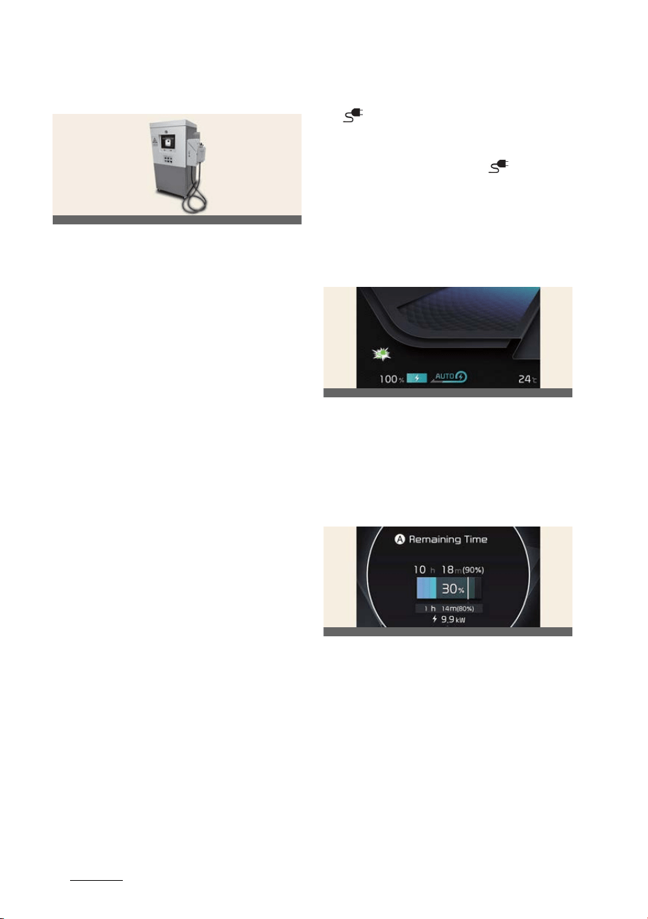
7. Check if the charging indicator light
( ) of the high voltage battery in the
instrument cluster is turned ON.
Charging is not active when the
charging indicator light ( ) is OFF.
When the charging connector and
charging plug are not connected
properly, reconnect the charging
cable to charge.
8. After charging has started, the esti
-
mated charging time is displayed on
the instrument cluster for about 1
minute.
If you open the driver seat door while
charging, the estimated charging time
is also displayed on the instrument
cluster for about 1 minute. When
scheduled charging or scheduled air
conditioner/heater is set, the esti
-
mated charging time is displayed as "-
-".
A:
Remaining Time
Checking charging status
When charging the high voltage battery,
the charge level can be checked from
outside the vehicle.
OCVQ011007L
OCVQ011012L
OCV041299L
OCV041103L
25
2
2
Electric vehicle guide AC charge
For more details, refer to "Charge indica
-
tor lamp for electric vehicle" on page 2-
19.
How to disconnect AC charger
1. When charging is complete, remove
the charging plug from the electrical
outlet of the AC charging station.
2. Hold the charging connector handle
and pull it out.
3. Make sure to completely close the
charging door.
4. Close the protection caps of the
charging connector and the charging
plug to protect them from foreign
substances.
5. If the personal charging connector is
used, store the connector in the cable
compartment.
NOTICE
僅 If you cannot open the charging door
due to freezing weather, tap lightly or
remove any ice near the charging
door. Do not try to forcibly open the
charging door.
僅 Locking Charging Cable Select
Set
-
tings
→
Vehicle
→
ECO Vehicle
→
Charging connector locking mode
in the infotainment. The charging con
-
nector is locked in the inlet at a differ
-
ent period according to which mode is
selected.
-
Always lock
mode: The connector
locks when the charging connector
is plugged into the charging inlet.
-
Lock while charging
mode: The
connector locks when charging
starts.
僅 Even though charging is possible with
the EV button in the ON/START posi
-
tion, for you safety, start charging
when the EV button is in the OFF posi
-
tion and the vehicle shifted to P
(Park). After charging has started, you
can use electrical components such as
the radio by pressing the EV button to
the ACC or ON position.
僅 During AC charging, the radio recep
-
tion may be bad.
僅 During charging, the gear cannot be
shifted from P (Park) to any other
gear.
僅 Depending on the condition and dura
-
bility of the high voltage battery, char
-
ger specifications, and ambient
temperature, the time required for
charging the battery may vary.
OCVQ011007L
OCVQ011019L
Electric vehicle guide
262
DC charge
DC charge
You can charge at high speeds at public
charging stations. Refer to the respec
-
tive company's manual that is provided
for each DC charger type.
Battery performance and durability can
deteriorate if the DC charger is used
constantly.
Use of DC charge should be minimized
in order to help prolong high voltage
battery life.
Actual charger image and charging
method may vary in accordance with
the charger manufacturer.
How to connect DC charger
1. Depress the brake pedal and apply
the parking brake.
2. urn OFF all switches, shift to P (Park),
and turn OFF the vehicle.
3. Open the charging door.
For more details, refer to
"Electric
charging door" on page 2-21
.
4. Check whether there is dust or foreign
substances inside the charging con
-
nector and charging inlet.
5. Hold the charging connector handle
and connect it to the vehicle charging
inlet. Push the connector all the way
in. If the charging connector and
charging terminal are not connected
properly, this may cause a fire. Refer
to the manual for each type of DC
charger for how to charge and
remove the charger.
6. Check if the charging indicator light
( ) of the high voltage battery in the
instrument cluster is turned ON.
Charging is not active when the
charging indicator light ( ) is OFF.
When the charging connector is not
connected properly, reconnect the
charging cable to charge it again.
During cold weather, DC charging
may not be available to prevent high
voltage battery degradation.
7. After charging has started, the esti
-
mated charging time is displayed on
the instrument cluster for about 1
minute. If you open the driver seat
door while charging, the estimated
charging time is also displayed on the
instrument cluster for about 1 minute.
A:
Remaining Time
Checking charging status
When charging the high voltage battery,
the charge level can be checked from
outside the vehicle.
For more details, refer to "Charge indica
-
tor lamp for electric vehicle" on page 2-
19.
OCVQ011008L
OCV041299L
OCV041104L

27
2
2
Electric vehicle guide DC charge
How to disconnect DC charger
1. Remove the charging connector when
DC charging is completed, or after
you stop charging using the DC char
-
ger. Refer to each respective DC char
-
ger manual for details about how to
disconnect the charging connector.
2. Make sure to completely close the
charging door.
CAUTION
High frequency noise may be intermit
-
tently heard from outside the vehicle
when charging with old DC charging sta
-
tions or DC charging stations with com
-
munication delay.
This high frequency noise is heard when
the vehicle operates the function to
reduce electromagnetic waves on its
own to maintain charging. Thus, it is the
normal functional behavior of the vehi
-
cle which does not affect charging or
vehicle performance.
NOTICE
僅If you use a DC charger when the
vehicle is already fully charged, some
DC chargers will send out an error
message. When the vehicle is fully
charged, do not charge the vehicle.
僅 If you cannot open the charging door
due to freezing weather, tap lightly or
remove any ice near the charging
door. Do not try to forcibly open the
charging door.
僅 To control the temperature of the high
voltage battery while charging, the air
conditioner is used to cool down the
battery which may generate noise
from operation of the air conditioner
compressor and cooling fan.
Also, the air conditioner's perfor
-
mance may be degraded during sum
-
mer due to operation of the cooling
system for the high voltage battery.
僅 Even though charging is possible with
the EV button in the ON/START posi
-
tion, for you safety, start charging
when the EV button is in the OFF posi
-
tion and the vehicle shifted to P
(Park). After charging has started, you
can use electrical components such as
the radio by pressing the EV button to
the ACC or ON position.
During charging, the gear cannot be
shifted from P (Park) to any other
gear.
僅 Depending on the condition and dura
-
bility of the high voltage battery, char
-
ger specifications, and ambient
temperature, the time required for
charging the battery may vary.
Electric vehicle guide
282
Portable charge
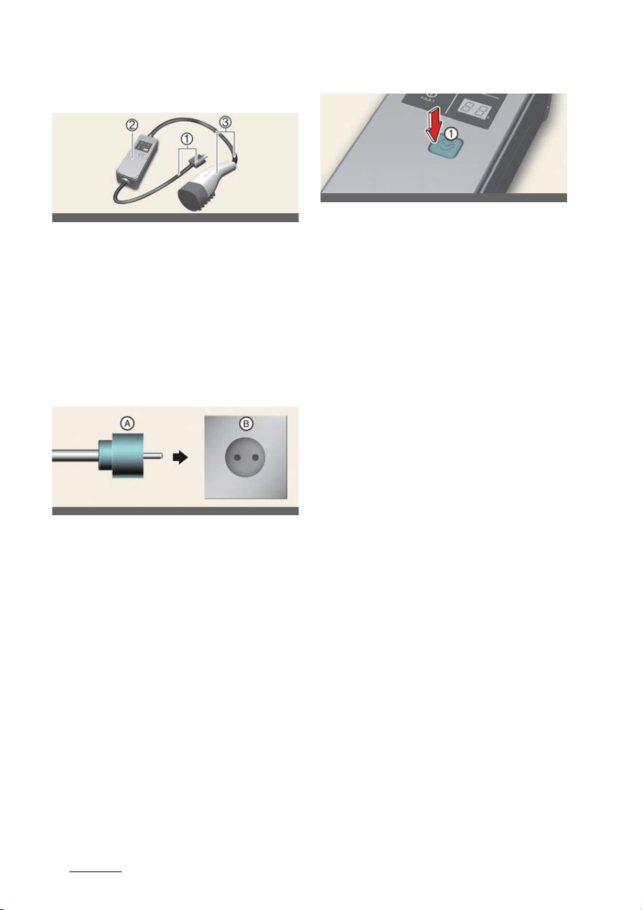
Portable charge
1
Code and Plug (Code set)
2
Control Box
3
Charging Cable and Charging Con
-
nector
Portable Charge can be used when AC
Charge or DC Charge is not available by
using household electricity.
Setting the charge level of the
portable charger
僅A: Plug
僅B: Electric Outlet
1. Check the rated current of the electric
outlet prior to connecting the plug to
the outlet.
2. Connect the plug to a household elec
-
tric outlet.
3. Check the display window on the con
-
trol box.
4. Press the button (1) on the back of the
control box for 2 to 8 seconds to
adjust the charge level. (Refer to
charging cable type and example for
setting the charge level.)
5. The charge level on the display win
-
dow of the control box changes every
time you press the button (1).
6. When setting the charge level is com
-
plete, start charging according to the
portable charge procedure.
OCVQ011020L
OCVQ011022L
OCVQ011021L
29
2
2
Electric vehicle guide Portable charge
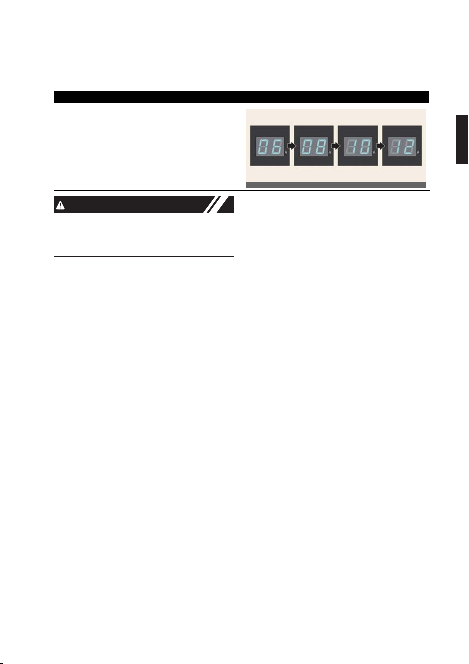
* Example for setting the ICCB charge level
* The example is only for reference and may vary according to the surrounding environment.
CAUTION
Please make sure that charge level
selection matches the capacity of your
circuit breaker to avoid blown fuse.
Outlet current ICCB charge level Control box display window
14-16A 12A
13-12A 10A
11-10A 8A
9-8A 6A
OCVQ011023L
Electric vehicle guide
302
Portable charge
How to connect portable charger
(ICCB: In-Cable Control Box)
1. Connect the plug to a household elec
-
tric outlet.
僅A: Plug
僅 B: Electric Outlet
2. Check if the power lamp (green) illu
-
minates on the control box.
3. Depress the brake pedal and apply
the parking brake.
4. Turn OFF all switches, shift to P
(Park), and turn OFF the vehicle. If
charging is initiated without the gear
in P (Park), the charging will start after
the gear is automatically shifted to P
(Park).
5. Open the charging door.
For more details, refer to
"Electric
charging door" on page 2-21
.
6. Open the protection caps of the
charging connector and the charging
plug. Check if there are any foreign
substances or dust.
7. Hold the charging connector handle
and connect it to the vehicle charging
inlet. Push the connector all the way
in. If the charging connector and
charging terminal are not connected
properly, this may cause a fire.
8. Charging starts automatically
(charging lamp illuminates).
9. Check if the charging indicator light
( ) of the high voltage battery in the
instrument cluster is turned ON.
Charging is not active when the
charging indicator light ( ) is OFF.
When the charging connector is not
connected properly, reconnect the
charging cable to charge it again.
10.After charging has started, the esti
-
mated charging time is displayed on
the instrument cluster for about 1
minute.
A:
Remaining Time
If you open the driver seat door while
charging, the estimated charging time
is also displayed on the instrument
cluster for about 1 minute. When
scheduled charging or scheduled air
conditioner/heater is set, the esti
-
mated charging time is displayed as "-
-".
OCVQ011022L
OCVQ011024
OCVQ011025
OCV041299L
OCV041103L

31
2
2
Electric vehicle guide Portable charge
Checking charging status
When charging the high voltage battery,
the charge level can be checked from
outside the vehicle.
For more details, refer to "Charge indica
-
tor lamp for electric vehicle" on page 2-
19.
NOTICE
僅 If you cannot open the charging door
due to freezing weather, tap lightly or
remove any ice near the charging
door. Do not try to forcibly open the
charging door.
僅 Locking Charging Cable Select
Set
-
tings
→
Vehicle
→
ECO Vehicle
→
Charging connector locking mode
in the infotainment system. The
charging connector is locked in the
inlet at a different period according to
which mode is selected.
-
Always lock
mode: The connector
locks when the charging connector
is plugged into the charging inlet.
-
Lock while charging
mode: The
connector locks when charging
starts.
For more details, refer to
"Charging
connector lock" on page 2-19
.
僅 Even though charging is possible with
the EV button in the ON/START posi
-
tion, for you safety, start charging
when the EV button is in the OFF posi
-
tion and the vehicle shifted to P
(Park). After charging has started, you
can use electrical components such as
the radio by pressing the EV button to
the START or ON position.
During charging, the gear cannot be
shifted from P (Park) to any other
gear.
僅 Depending on the condition and dura
-
bility of the high voltage battery, char
-
ger specifications, and ambient
temperature, the time required for
charging the battery may vary.
Electric vehicle guide
322
Portable charge
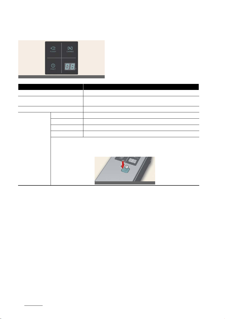
Charging status indicator lamp for portable charger
OCVQ011026L
Indicator Details
POWER
On: Power on
CHARGE
On: Charge Blink: Current limit due to high plug temperature or high internal tem
-
perature
FAULT
Blink: Charging interrupted
CHARGE LEVEL
12 12 A
10 10 A
08 8 A
06 6 A
The charging current changes whenever the button (1) is pressed for less than 1 sec with the charger
plugged into an electrical outlet but not the vehicle.
Control box
OCVQ011021L
33
2
2
Electric vehicle guide Portable charge
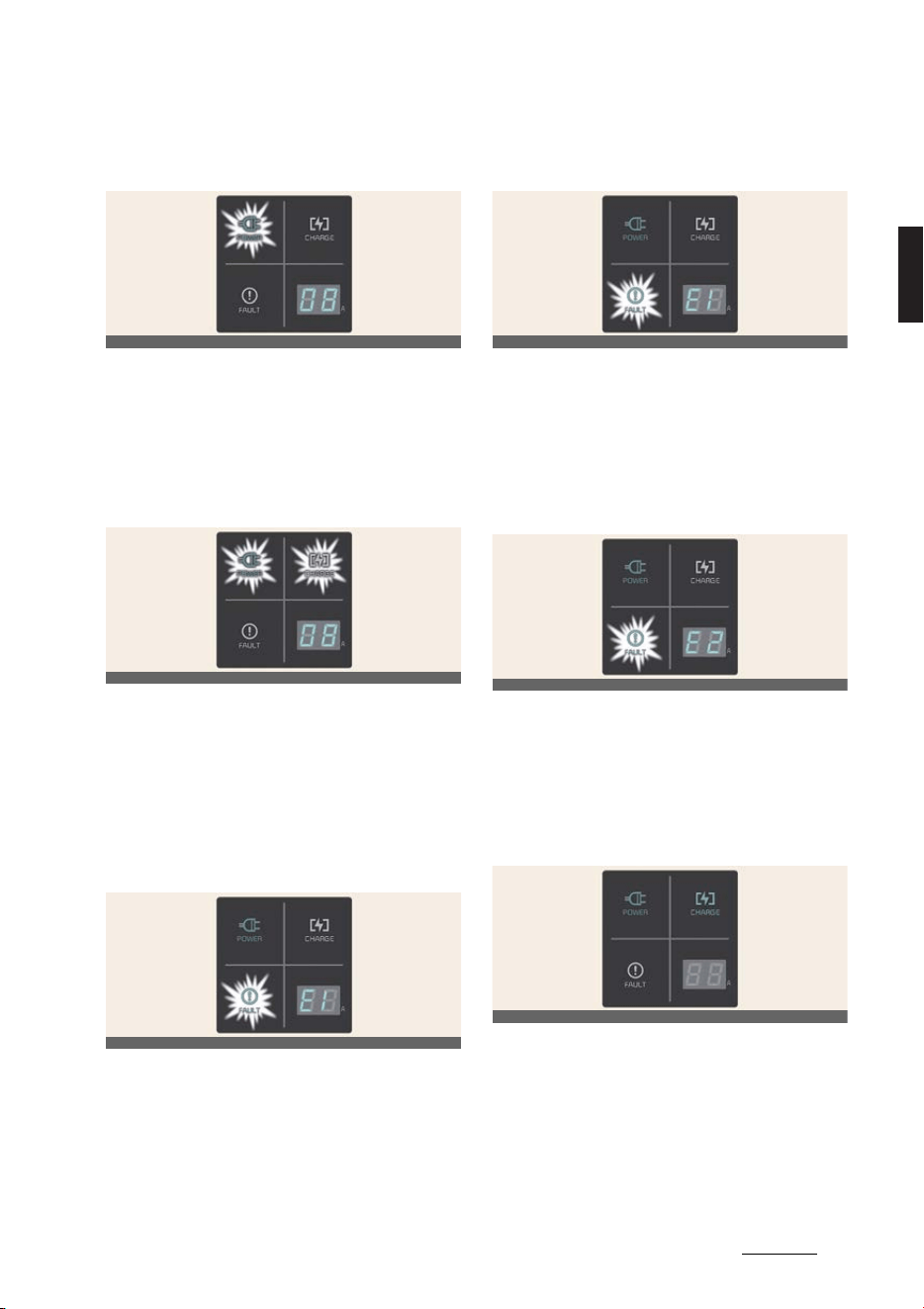
Status/Diagnosis/Countermea
-
sure
僅 Charging connector plugged into
vehicle (
POWER
Green ON)
僅 Plug connected to an electric outlet
(
POWER
Green ON)
While charging
僅Charge indicator (
POWER
Green ON/
CHARGE
Blue ON)
僅Charging current
Before plugging charging con
-
nector into vehicle (POWER
Green ON, FAULT Red blink)
僅Abnormal temperature
僅 CCB (In-Cable Control Box) failure
Plugged into vehicle (POWER
Green ON, FAULT Red Blink)
僅 Diagnostic device failure
僅Current leakage
僅 Abnormal temperature
Leakage current failure (POWER
Green ON, FAULT Red Blink)
僅 After disconnecting and reconnecting
the power plug, press and release the
button for 2 seconds or longer to clear
the error.
Power saving mode
僅 Charge level indicator is turned off if
there is no status change for more
than 1 minute.
OCVQ011024
OCVQ011025
OCVQ011027L
OCVQ011027L
OCVQ011028L
OCVQ011029L
Electric vehicle guide
342
Portable charge
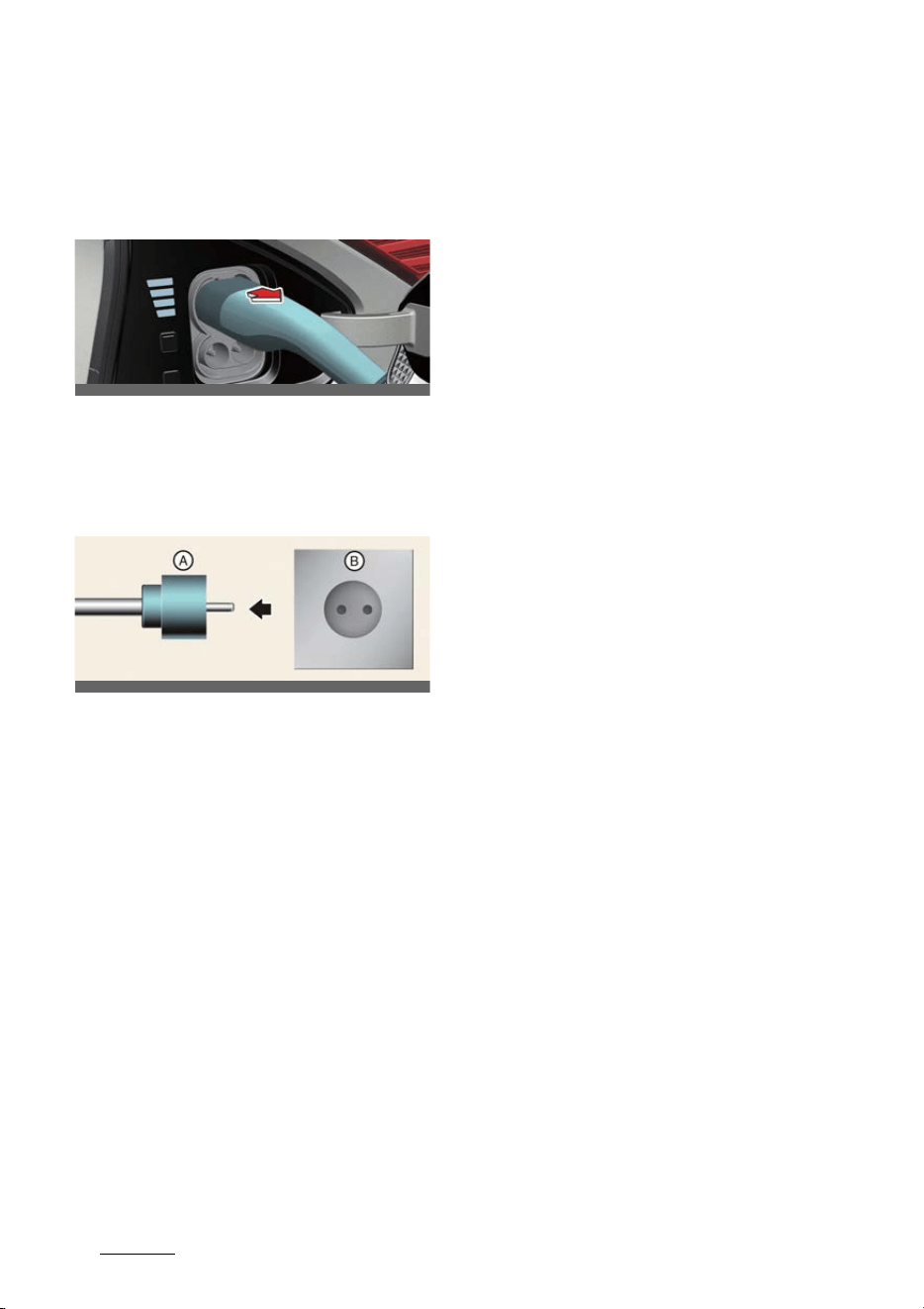
How to disconnect portable char
-
ger (ICCB: In-Cable Control Box)
1. Hold the charging connector handle
and pull it out.
2. Make sure to completely close the
charging door.
3. Disconnect the plug from the house
-
hold electric outlet. Do not pull the
cable when disconnecting the plug.
A: Plug
B: Electric Outlet
4. Close the protection caps of the
charging connector and the charging
plug to protect them from foreign
substances.
5. If the personal charging connector is
used, store the connector in the cable
compartment.
Precautions for portable charger
(ICCB: In-Cable Control Box)
僅 Use the portable charger that is certi
-
fied by an authorized Kia dealer/ser
-
vice partner.
僅 Do not try to repair, disassemble, or
adjust the portable charger.
僅 Do not use an extension cord or
adapter.
僅 Stop using immediately when failure
occurs.
僅 Do not touch the plug and charging
connector with wet hands.
僅 Do not touch the terminal part of the
AC charging connector and the AC
charging inlet on the vehicle.
僅 Do not connect the charging connec
-
tor to voltage that does not comply
with regulations.
僅 Do not use the portable charger if it is
worn out, exposed, or there exists any
type of damage on the portable char
-
ger.
僅 If the ICCB case and AC charging con
-
nector is damaged, cracked, or the
wires are exposed in any way, do not
use the portable charger.
僅 Do not let children operate or touch
the portable charger.
僅 Keep the control box free of water.
僅 Keep the normal charging connector
or plug terminal free of foreign sub
-
stances.
僅 Do not step on the cable or cord. Do
not pull the cable or cord and do not
twist or bend it.
僅 Do not charge when there is lightning.
僅 Do not drop the control box or place a
heavy object on the control box.
僅 Do not place an object that can gener
-
ate high temperatures near the char
-
ger when charging.
僅 Charging with the worn out or dam
-
aged household electric outlet can
result in a risk of electric shock. If you
are in doubt to the household electric
outlet condition, have it checked by a
licensed electrician.
僅 Stop using the portable charger
immediately if the household electric
OCVQ011019L
OCVQ011030L

35
2
2
Electric vehicle guide Charging the electric vehicle (Abrupt stop)
outlet or any components is over
-
heated or you notice burnt odors.
NOTICE
To prevent charging cable theft, the
charging connector cannot be discon
-
nected from the inlet when the doors are
locked or the charging connector is in
the
Always lock
mode. Unlock all doors
to disconnect the charging connector
from the inlet.
However, if the vehicle is in the charging
connector
Lock while charging
mode,
the charging connector automatically
unlocks from the inlet when charging is
completed.
If the charging connector is discon
-
nected while the release button is not
pressed, the connector and the inlet may
be damaged.
For more details, refer to "Charging con
-
nector lock" on page 2-19.
If the release button does not work even
after the all doors are unlocked, pull the
emergency lift cable in the motor room
and press the release button in the con
-
nector to disconnect it from the vehicle.
If the release button still does not work,
we recommend to visit an authorized Kia
dealer/service partner.
Charging the electric vehicle
(Abrupt stop)
Action to be taken when charging
stops abruptly
When the high voltage battery does not
charge, check the followings:
僅 Check the charging setting for the
vehicle. Refer to "EV settings" on page
2-14 (e.g. When scheduled charging is
set, charging is not initiated immedi
-
ately when the AC charger or portable
charger (ICCB: In-Cable Control Box)
is connected.)
僅 Check the operation status of AC
charger, portable charger and DC
charger. (Refer to "Charging status"
on page 2-19)
* Actual method for indicating the
charging status may vary in accor
-
dance with the charger manufac
-
turer.
僅 When the vehicle does not charge and
a warning message appears on the
cluster, check the corresponding mes
-
sage. Refer to "LCD display messages"
on page 2-41.
僅 If the vehicle is properly charged
when charged with another normally
working charger, contact the charger
manufacturer.
僅 If the vehicle does not charge when
charged with another normally work
-
ing charger, we recommend that you
contact an authorized Kia dealer/ser
-
vice partner for inspection.
僅 If charging fails and the service warn
-
ing light ( ) is lit in the cluster, we
recommend that you contact an
authorized Kia dealer/service partner.
Electric vehicle guide
362
Driving electric vehicle
Driving electric vehicle
This section describes how to start and
stop the vehicle, what is displayed on the
various gauges and LCD displays, and so
on.
Starting the vehicle
1. Holding the smart key, sit in the
driver's seat.
2. Fasten the seat belt before starting
the vehicle.
3. Make sure to engage the parking
brake.
4. Check the position of the accelerator
pedal and the brake pedal and the
clearance with your right foot.
5. Make sure to depress and hold the
brake pedal.
6. While depressing the brake pedal,
shift to P (Park).
7. Depress and hold the brake pedal
while pressing the EV button.
8. When the
READY
indicator is ON, you
can drive the vehicle. When the
READY
indicator is OFF, you cannot
drive the vehicle. Restart the vehicle.
Vehicle ON →
READY
(green)
9. Depress and hold the brake pedal and
shift to the desired position
10.Release the parking brake and slowly
release the brake pedal. Check if the
vehicle slowly moves forward, then
depress the accelerator pedal.
Stopping the vehicle
1. Hold down the brake pedal while the
vehicle is parked.
2. Shift to P (Park).
3. Engage the parking brake.
4. Press the EV button and turn off the
vehicle.
5. Check if the
READY
indicator is
turned OFF in the instrument cluster.
When the
READY
indicator in ON and
the gear is in a position other than P
(Park), the driver can accidentally
depress the accelerator pedal, caus
-
ing the vehicle to move unexpectedly.
Vehicle OFF
Virtual Engine Sound System
(VESS)
The Virtual Engine Sound System (VESS)
generates an engine sound for pedestri
-
ans to hear the vehicle because there is
no sound while the Electric Vehicle (EV)
is operating.
If the vehicle is in the ready mode and
the gear is not in P (Park), the VESS will
operate.
When the gear is shifted to R (Reverse),
an additional warning sound will be
heard.
WARNING
The sound system only plays a supple
-
mentary role. The system is not
designed to and does not replace the
care of drivers. Drivers should always
OCV041156L
OCV041157L
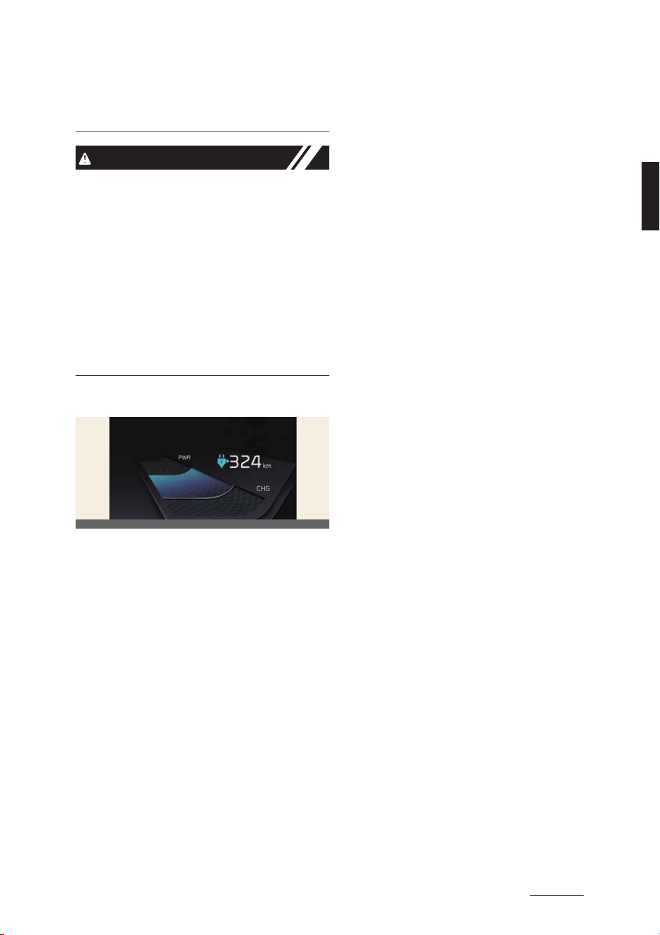
37
2
2
Electric vehicle guide Driving electric vehicle
pay attention to their surroundings while
driving.
CAUTION
僅 The vehicle does not generate an
engine sound. Be aware of your driv
-
ing environment and drive safely.
僅 After you park the vehicle or while you
are waiting at a traffic light, check
whether there are children or obsta
-
cles around the vehicle.
僅 Check if there is something behind
the vehicle when driving in reverse.
Pedestrians may not hear the sound
of the vehicle.
Distance to empty
The distance to empty is displayed dif
-
ferently according to the selected drive
mode in the Drive Mode Integrated Con
-
trol System.
For more information, refer to "Drive
mode integrated control system" on
page 6-35.
Impact on distance to empty
僅 Driving range depends on the driving
style, electrical load usage, environ
-
ment, and high voltage battery
energy. Distance to empty displayed
on the vehicle may be higher or lower
than the certification range because
these effects are considered.
僅 Driving style refers to driving speed
and acceleration/deceleration ten
-
dency. The higher the speed, or the
more frequent the acceleration/decel
-
eration, distance to empty will be
reduced.
僅 Electrical loads usage means air con
-
ditioning, heaters, lamps or additional
auxillary loads, and as the usage
increases, distance to empty will be
reduced.
僅 Environment refers to weather, tem
-
perature, and terrain. Distance to
empty is reduced in cases of snow/
rain/high winds or low temperatures,
uphill or slippery or rough road sur
-
faces.
僅 High voltage battery energy is propor
-
tional to SOC (charge amount), but
may vary depending on the battery
temperature, SOH (battery health),
etc.
Change of distance to empty
when 100% charging
僅If the distance to empty is lowered
due to learning by the driving style or
the environment in which the vehicle
is used, the driving distance may be
increased again if the vehicle contin
-
ues to drive according to the "driving
tips for improving the driving dis
-
tance". The distance to empty can be
reset at the workshop, but it does not
actually increase the range. There
-
fore, the distance to empty may be
inaccurate until the learning proceeds.
僅 Distance to empty decreases when
the high voltage battery temperature
is low in winter. It is not a permanent
change. If the temperature rises, the
distance to empty is restored.
僅 Reducing the use of electrical loads
increases the range available.
僅 Natural degradation of the high volt
-
age battery occurs depending on the
OCV041421L
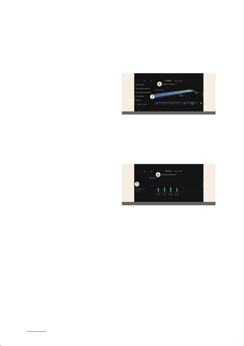
Electric vehicle guide
382
Driving electric vehicle
length of use of the vehicle, which
reduces the distance to empty.
Operating tips to improve driving
range.
僅 As electric vehicles speed up, air resis
-
tance increases rapidly, so not speed
-
ing helps more driving range.
僅 High driving energy is consumed
during rapid acceleration. Motor
regenerative braking is restricted
during rapid deceleration. Keep the
accelerator pedal position constant
and drive at a constant speed.
僅 Excessive operation of the heater and
air conditioner can increase power
consumption and shorten the driving
range. When setting the temperature
to 22°C auto, optimal energy con
-
sumption driving is possible. In partic
-
ular, using a heated seat and reducing
air heating in winter is very helpful.
Turn off the heater and air conditioner
when heating and cooling are not
needed.
僅 Selecting recirculation mode con
-
sumes less energy than selecting
fresh mode. In the fresh mode, energy
consumption is large because the out
-
door air must be reheated or cooled.
When driving with the window open,
air resistance increases and heater
and air conditioner usage increases.
So close the window completely while
driving to reduce energy consump
-
tion.
僅 When driving alone, use DRIVER
ONLY mode when using the heater
and air conditioning system.
僅 Always maintain the specified tire
pressure and use tires exclusively for
electric vehicles.
僅 Do not use unnecessary electrical
components while driving.
僅 Do not load unnecessary items in the
vehicle.
僅 Do not mount parts that may increase
air resistance.
ECO driving
A:
Electric Vehicle
1 ECO driving
In order to check the ECO driving his
-
tory, select Menu →
ECO driving
on the
screen.
Electric energy economy history
A:
ECO driving
1 Energy consumption history
It is possible to check the history of elec
-
tric energy economy with the date and
distance of previous driving. The icon is
displayed on the most efficient electric
energy economy record.
Energy consumption
In order to check the current energy
consumption for each system of the
vehicle, select Menu →
Energy con
-
sumption
on the screen.
OCVGT042422L
OCVGT042423L
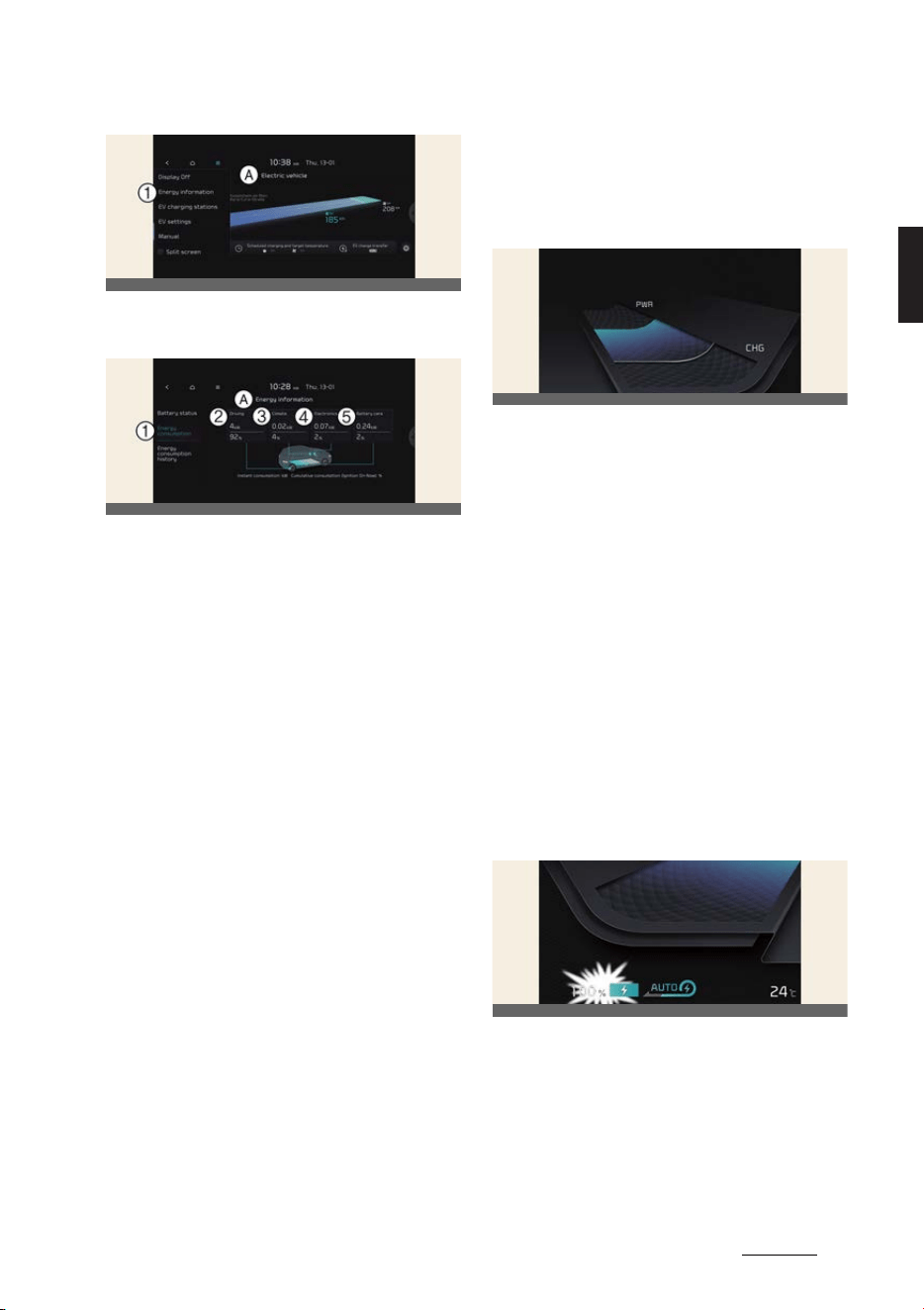
39
2
2
Electric vehicle guide Driving electric vehicle
A:
Electric Vehicle
1 Energy information
A:
Energy information
1 Energy consumption
2 Driving
3 Climate
4 Electronics
5 Battery care
1.
Driving
shows the total power and
energy consumption of the driving
motor's driving energy and regenera
-
tive energy.
2.
Climate
shows the power and energy
consumption which are used by the
heater or air conditioner.
3.
Electronics
shows the power and
energy consumption which are used
by the vehicle systems including the
cluster, infotainment system (speaker
and navigation), headlamp, vehicle
control unit, etc.
4.
Battery care
shows the momentary
power and energy consumption
which are used when:
僅 Operating the battery conditioning
mode to increase the battery tem
-
perature during winter to improve
the driving performance.
僅 Cooling down the battery tempera
-
ture during summer to prevent
over temperature of the battery.
Power/Charge gauge
The Power/Charge Gauge shows the
energy consumption rate of the vehicle
and the charge/discharge status of the
regenerative brakes.
僅Power
PWR
: It shows the energy con
-
sumption rate of the vehicle when
driving uphill or accelerating. The
more electric energy is used, the
higher the gauge level.
僅Charge
CHG
: It shows the charging
status of the battery when it is being
charged by the regenerative brakes
(decelerating or driving on a downhill
road). The more electric energy is
charged, the lower the gauge level.
State of charge (SOC) gauge for
high voltage battery
The SOC gauge shows the charging sta
-
tus of the high voltage battery.
The low percentage number on the indi
-
cator indicates that there is not enough
energy in the high voltage battery. 100%
indicates that the driving battery is fully
charged.
OCVGT042424L
OCVGT042129L
OCV041130L
OCV041131L

Electric vehicle guide
402
Driving electric vehicle
When driving on highways or motor
-
ways, make sure to check in advance if
the driving battery is charged enough.
When the remaining battery is lower
than 10% (15% for GT) on the SOC
gauge, the warning light ( ) turns ON to
alert you of the battery level.
If the distance to empty is insuffi
-
cient
僅 If the battery warning light is on,
recharge immediately at the nearest
charging station.
僅 Drive efficiently according to Operat
-
ing tips to improve driving range.
Refer to "Operating tips to improve
driving range." on page 2-38.
僅 If the remaining battery is 0%, do not
drive too hard and go to a safe place
to request rescue.
Warning and indicator lights
(related to electric vehicle)
Ready indicator READY
僅 This indicator illuminates:
When the vehicle is ready to be
driven.
- ON: Normal driving is possible.
- OFF: Normal driving is not possible,
or a problem has occurred.
- Blinking: Emergency driving.
When the ready indicator goes OFF or
blinks, there is a problem with the sys
-
tem. In this case, we recommend to visit
an authorized Kia dealer/service partner.
Service warning light
This warning light illuminates:
僅 When the EV button is in the ON posi
-
tion.
- It illuminates for approximately 3
seconds and then goes off.
僅 When there is a problem with related
parts of the electric vehicle control
system, such as sensors, etc.
When the warning light illuminates while
driving, or does not go OFF after starting
the vehicle, we recommend to visit an
authorized Kia dealer/service partner.
Power down indicator light
This indicator light illuminates:
僅 When the EV button is in the ON posi
-
tion.
- It illuminates for approximately 3
seconds and then goes off.
僅 When the power is limited for the
safety of the high-powered parts of
an electric vehicle. The power is lim
-
ited for the following reasons.(Unless
both Service Warning Light and
Power Down Indicator Light illuminate
at the same time, it is not a failure.)
- The high voltage battery level is too
low or voltage is decreasing
- The temperature of the high volt
-
age battery is too high or too low
- The temperature of the motor is
high
NOTICE
僅 Do not accelerate or start the vehicle
suddenly when the power down indi
-
cator light is ON.
OCV042641
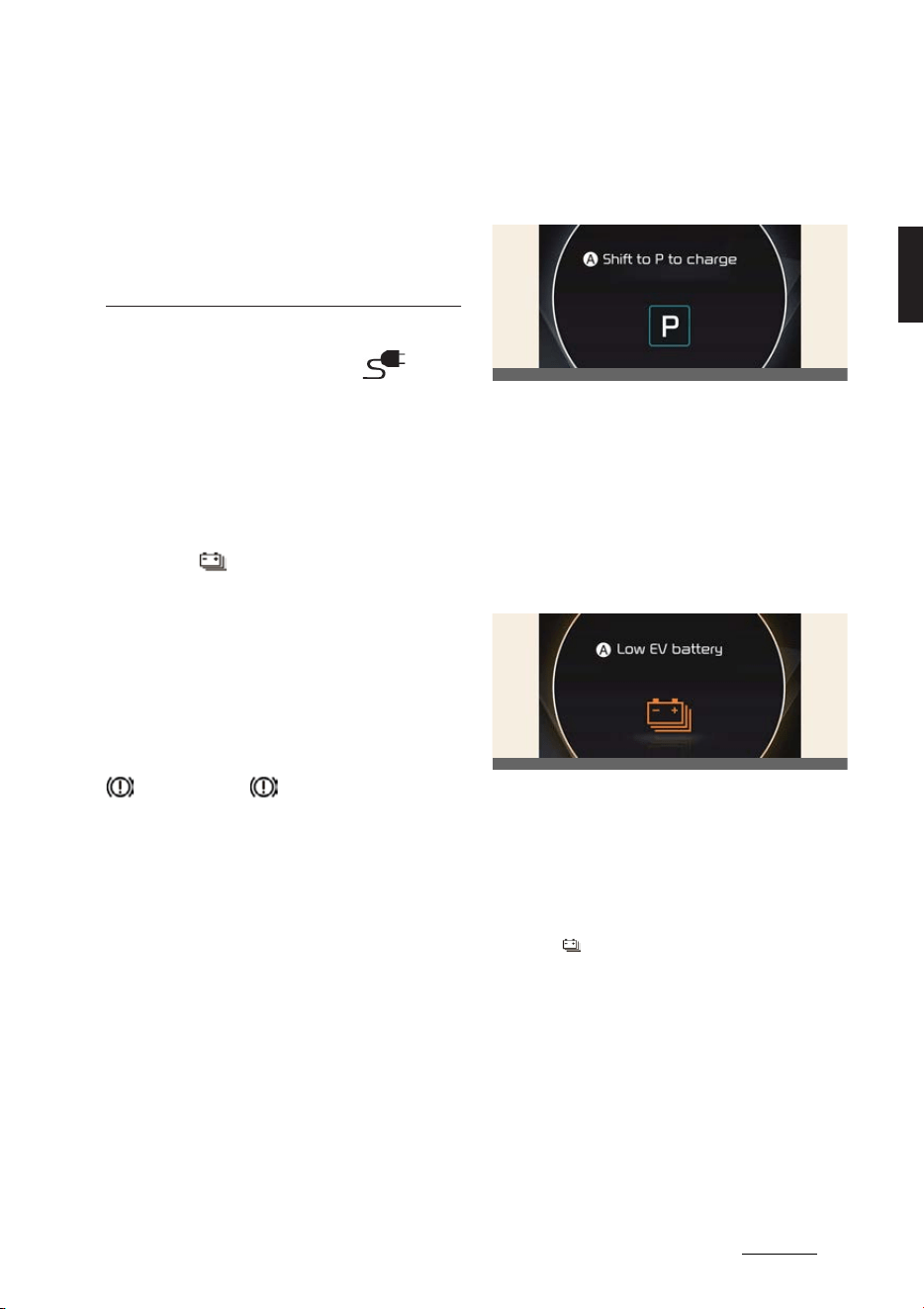
41
2
2
Electric vehicle guide Driving electric vehicle
僅 When the power is limited for the
safety of the high-powered parts of
an electric vehicle, the power down
indicator light illuminates. Your vehi
-
cle may not be driven, or may roll
back on a slope with the indicator
light ON.
Charging indicator light
This warning light illuminates:
僅 When the charging connector is con
-
nected to charge the high voltage bat
-
tery.
High voltage battery level warn
-
ing light
This warning light illuminates:
僅 When the high voltage battery level is
low.
僅 When the warning light turns ON,
charge the battery immediately.
Regenerative brake warning light
(red color) (yellow color)
This warning light illuminates:
僅 When the regenerative brake does
not operate and the brake does not
perform well. This causes the Brake
Warning light (red) and Regenerative
Brake Warning Light (yellow) to illumi
-
nate simultaneously.
In this case, drive safely and we recom
-
mend that you have your vehicle
inspected by an authorized Kia dealer/
service partner.
The operation of the brake pedal may be
more difficult than normal and the brak
-
ing distance can increase.
LCD display messages
Shift to P to charge
A:
Shift to P to charge
This message is displayed if you connect
the charging cable without the gear in
the P (Park) position.
Shift to P (Park) before connecting the
charging cable.
Low EV battery
A:
Low EV battery
When the high voltage battery level
reaches around 10% (around 15% for GT)
or less, this warning message is dis
-
played.
The warning light on the instrument
cluster ( ) will turn on simultaneously.
Charge the battery immediately.
OCV041105L
OCV041112L
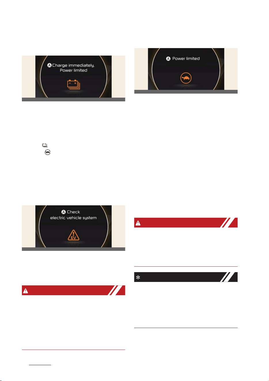
Electric vehicle guide
422
Driving electric vehicle
Charge immediately. Power lim
-
ited
A:
Charge immediately. Power limited
When the high voltage battery level
reaches around 5% or less, this warning
message is displayed.
The warning light on the instrument
cluster ( ) and the power down indica
-
tor light ( ) will turn on simultaneously.
The vehicle's power will be reduced to
minimize the energy consumption of the
high voltage battery. Charge the battery
immediately.
Check electric vehicle system
A:
Check electric vehicle system
This warning message is displayed when
there is a problem with the electric vehi
-
cle control system.
WARNING
Refrain from driving when the warning
message is displayed.
If this occurs, park the vehicle in a safe
location and we recommend that you
tow your vehicle to the nearest autho
-
rized Kia dealer/service partner and
have the vehicle inspected.
Power limited
A:
Power limited
In the following cases, this warning mes
-
sage is displayed when the vehicle's
power is limited for safety.
僅 When the power is limited for the
safety of the high-powered parts of
an electric vehicle. The power is lim
-
ited for the following reasons. (Unless
both Service Warning Light and
Power Down Indicator Light illuminate
at the same time, it is not a failure.)
僅 The high voltage battery level is too
low or voltage is decreasing.
僅 The temperature of the high voltage
battery is too high or too low.
僅 The temperature of the motor is high.
WARNING
When this warning message is dis
-
played, do not accelerate or start the
vehicle suddenly. Charge the battery
immediately when the high voltage bat
-
tery level is not enough.
NOTICE
When the power is limited for the safety
of the high-powered parts of an electric
vehicle, the power down indicator light
illuminates. Your vehicle may not be
driven, or may roll back on a slope with
the indicator light ON.
OCV041519L
OCV041118L
OCV041113L
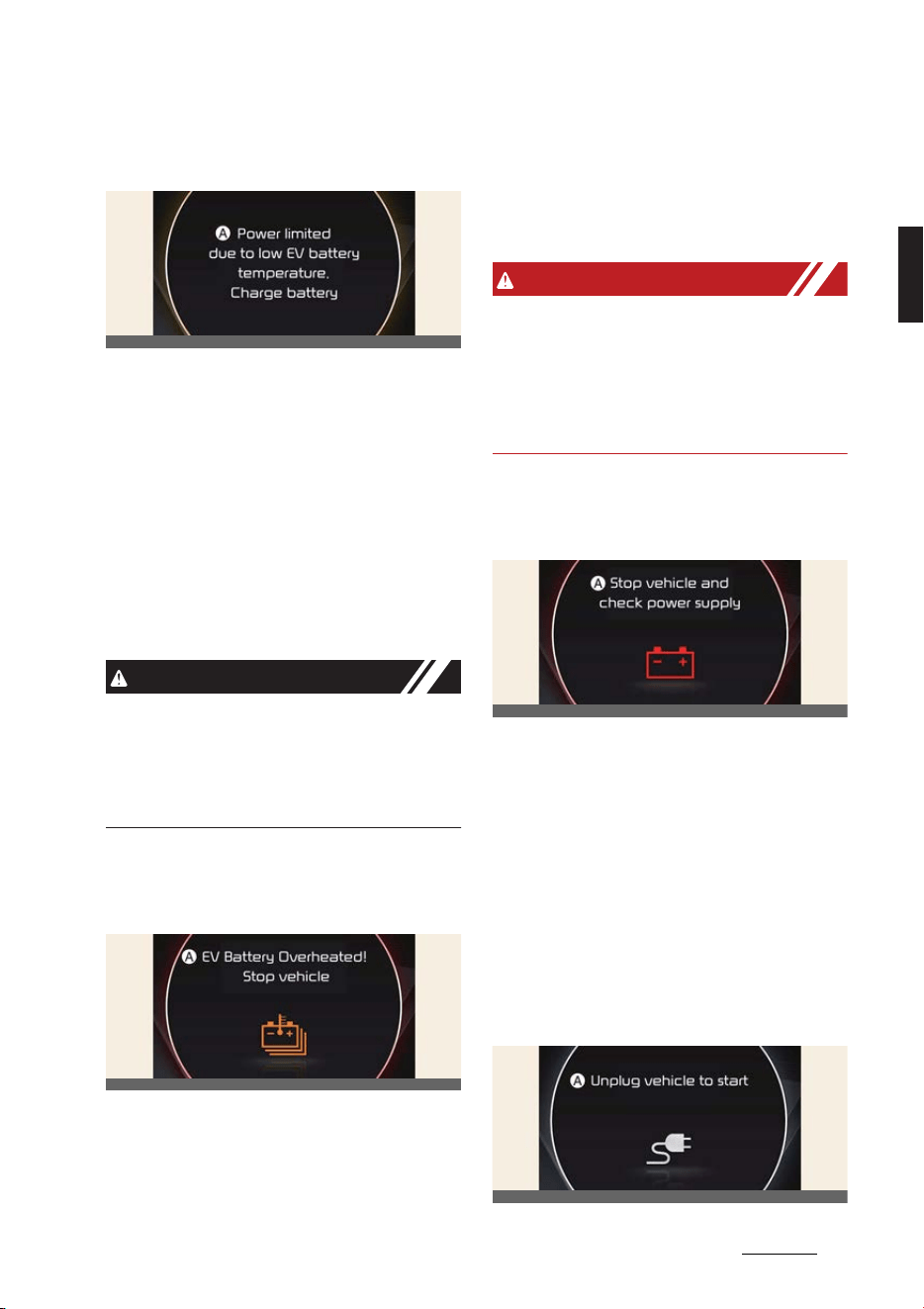
43
2
2
Electric vehicle guide Driving electric vehicle
Power limited due to low EV bat
-
tery temperature. Charge battery
A:
Power limited due to low EV battery
temperature. Charge battery
The warning message is displayed to
protect the electric vehicle system when
you turn off or turn on the vehicle while
outside temperature is low. If the high
voltage battery charging level is low and
parked outside in low temperature for a
long time, vehicle power could be lim
-
ited. Charging the battery before driving,
increases the battery temperature, and
helps increase power.
CAUTION
If this warning message is still displayed
even when the ambient temperature is
sufficiently high, have the vehicle
inspected by an authorized Kia dealer/
service partner.
EV Battery Overheated! Stop
vehicle
A:
EV Battery Overheated! Stop vehi
-
cle
This warning message is displayed to
protect battery and electric vehicle sys
-
tem when the high voltage battery tem
-
perature is too high.
Turn off the EV button and stop the
vehicle so that the battery temperature
decreases.
WARNING
If this warning is still displayed even
after the POWER button has been
turned off for sufficient time, refrain
from driving and have the vehicle
inspected by an authorized Kia dealer/
service partner.
Stop vehicle and check power
supply
A:
Stop vehicle and check power sup
-
ply
This warning message is displayed when
a failure occurs in the 12 V power supply
system.
If this occurs, park the vehicle in a safe
location and we recommend that you
tow your vehicle to the nearest autho
-
rized Kia dealer/service partner and
have the vehicle inspected.
Unplug vehicle to start
OCV041114L
OCV041115L
OCV041116L
OCV041106L
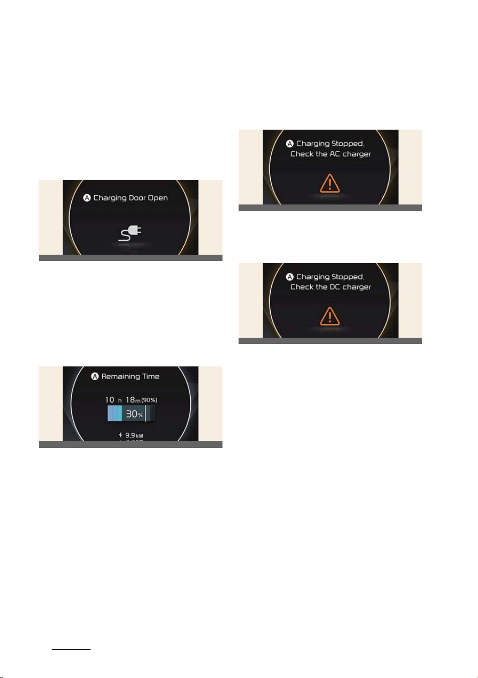
Electric vehicle guide
442
Driving electric vehicle
A:
Unplug vehicle to start
This message is displayed when you
start the vehicle, without unplugging the
charging cable, and will not shift out of
park. Unplug the charging cable, and
then turn on the vehicle.
Charging Door Open
A:
Charging Door Open
This message is displayed when the
vehicle is driven with the charging door
opened. Close the charging door and
then start driving.
Remaining Time
A:
Remaining Time
* The remaining charging time in the
LCD image may differ from actual
charging time.
This message is displayed to notify the
remaining time to charge the battery, to
the selected target battery charge level,
and the charge voltage level.
Charging Stopped. Check the AC
charger/Charging Stopped.
Check the DC charger
AC Charge
A:
Charging Stopped. Check the AC
charger
DC Charge
A:
Charging Stopped. Check the DC
charger
This warning message is displayed when
charging is stopped for the reasons
below:
僅 There is a problem with the external
AC charger or DC charger.
僅 The external AC charger stopped
charging
僅 The charging cable is damaged.
If this occurs, check whether there is any
problem with the external AC or DC
charger and charging cable.
If the same problem occurs when
charging the vehicle with a well-func
-
tioning external charger or genuine Kia
portable charger, have your vehicle
inspected by an authorized Kia dealer/
service partner.
OCV041107L
OCV041103L
OCV041108L
OCV041109L
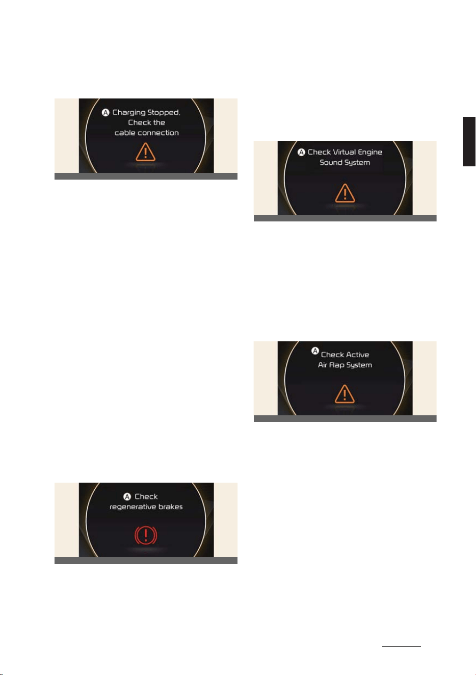
45
2
2
Electric vehicle guide Driving electric vehicle
Charging Stopped. Check the
cable connection
A:
Charging Stopped. Check the cable
connection
This warning message is displayed for
the reasons below:
僅 The charging connector is not cor
-
rectly connected to the charging inlet.
僅 The charging connector lock release
button is pressed.
If this occurs, separate the charging con
-
nector and re-connect it.
Check whether there is any problem
(external damage, foreign substances,
etc.) with the charging connector and
charging inlet.
If the same problem occurs when
charging the vehicle with a replaced
charging cable or genuine Kia portable
charger, we recommend that you have
your vehicle inspected by an authorized
Kia dealer/service partner.
Check regenerative brakes
A:
Check regenerative brakes
This warning message is displayed when
the regenerative brake system does not
work properly.
In this case, we recommend to visit an
authorized Kia dealer/service partner.
Check Virtual Engine Sound Sys
-
tem
A:
Check Virtual Engine Sound System
This message is displayed when there is
a problem with the Virtual Engine Sound
System (VESS).
In this case, we recommend to visit an
authorized Kia dealer/service partner.
Check Active Air Flap System
A:
Check Active Air Flap System
This warning message is displayed in the
following situations:
僅 There is a malfunction with the actua
-
tor flap
僅 There is a malfunction with the actua
-
tor air flap controller
僅 The air flap does not open
When all of the above conditions are
fixed, the warning will disappear.
OCV041110L
OCV041111L
OCV041117L
OCV041192L
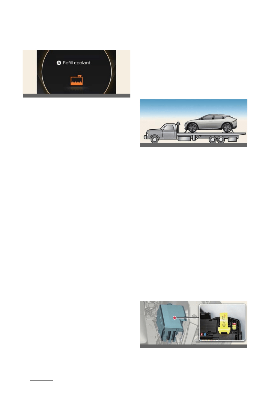
Electric vehicle guide
462
Safety precautions for electric vehicle
Refill coolant
A:
Refill coolant
This message is displayed when the
coolant is low. If the warning message is
displayed, stop driving and check the
amount of coolant. Driving under cool
-
ant for a prolonged period of time can
cause serious problems with the vehi
-
cle's electrical equipment and make nor
-
mal driving impossible.
Safety precautions for electric
vehicle
If an accident occurs
If towing is required, tow the vehicle with
a flatbed equipment or dollies with all
wheels off the ground.
If you must tow the vehicle using only
two wheels, lift the rear wheels off the
ground and tow the vehicle.
If necessary to roll the vehicle so that it
can be rolled onto a flatbed tow truck
perform the following:
僅 First, depress the brake pedal and
release the parking brake.
僅 Wait 3 minutes or more before open
-
ing the driver door and the vehicle will
remain in ACC mode and in N (Neu
-
tral).
僅 If the driver door is opened within the
3 minute period, the vehicle will auto
-
matically shift to P (Park), the vehicle
will turn OFF and the front wheels will
be remained locked.
High voltage cut-off switch
OCV041560L
OCV061024L
OCVQ011031L
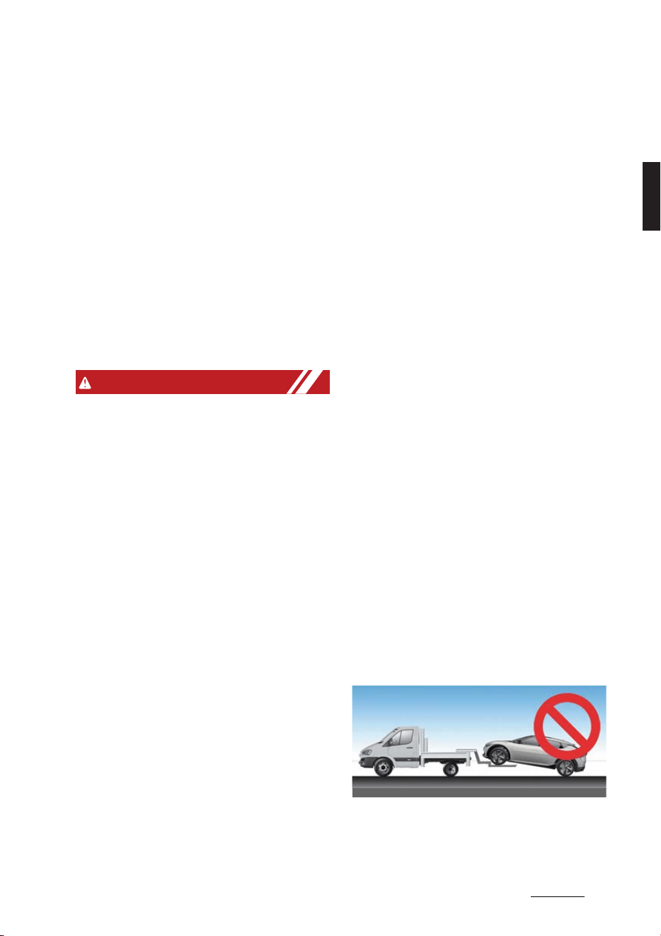
47
2
2
Electric vehicle guide Safety precautions for electric vehicle
Pull down the yellow lever in the high
voltage cut-off switch to shut down high
voltage battery.
Other precautions for electric
vehicle
僅 When you paint, apply heat treatment
to the vehicle as a result of an acci
-
dent, and/or weld on the vehicle, the
performance of the high voltage bat
-
tery can be reduced. If heat treatment
is required, have the vehicle serviced
by an authorized Kia dealer/service
partner and have the HV battery
removed, prior to any repairs.
WARNING
僅 When a vehicle accident occurs, move
the vehicle to a safe place, turn OFF
the vehicle and remove the auxiliary
battery (12 V) terminal to prevent high
voltage electricity from flowing.
僅 If electric wires are exposed from
inside or outside the vehicle, do not
touch the wires. Also, do not touch the
high voltage electric wire (orange),
connector, or any of the electric com
-
ponents and devices. This may cause
electric shock and lead to injuries.
僅 When a vehicle accident occurs and
the high voltage battery is damaged,
harmful gas and electrolytes may
leak. Be careful not to touch the
leaked liquid.
When you suspect leakage of inflam
-
mable gas and other harmful gases,
open the windows and evacuate to a
safe place. If any leaked fluid comes
in contact with your eyes or skin,
immediately clean the affected area
thoroughly with tap water or saline
solution and have doctors inspect it as
soon as possible.
僅 If a small scale fire occurs, use a fire
extinguisher (ABC, BC) that is meant
for electrical fires. If it is impossible to
extinguish the fire in the early stage,
maintain a safe distance away from
the vehicle and immediately call your
local fire emergency responders.
Also, advise them that an electric
vehicle is involved.
If the fire spreads to the high voltage
battery, large amounts of water is
needed to put out the fire. Using small
amounts of water or fire extinguishers
not meant for electrical fires could
cause serious injury or death from
electrical shocks.
僅 If you cannot put out the fire immedi
-
ately, the high voltage battery may
explode. Evacuate to a safe place and
do not let other people approach the
site.
Contact the fire department and
notify them of an electric vehicle fire.
If the vehicle is flooded with water,
immediately turn OFF the vehicle and
evacuate to a safe place. Contact the
fire department or an authorized Kia
dealer/service partner.
僅 If you tow the vehicle while the front
wheels are touching the ground, the
vehicle motor may generate electricity
and the motor components may be
damaged or a fire may occur.
僅 When a vehicle fire occurs due to the
battery, there is a risk of a second fire.
OCV061002L

Electric vehicle guide
482
Safety precautions for electric vehicle
Contact your local fire emergency
responders when towing the vehicle.
僅 When you clean the motor compart
-
ment, do not use high pressure water
to wash. This may cause an electric
shock due to a discharge in high volt
-
age electricity, or damage the vehi
-
cle's electric system.
僅 Never disconnect the high voltage
cut-off switch except in an emergency
situation. Serious problems may
occur, such as the vehicle will not
start.
CAUTION
僅 Do not use, remodel, or install non-
genuine parts. This may damage the
electric power system.
僅 The 4WD vehicle should never be
towed with the wheels on the ground.
This can cause serious damage to the
transmission or the 4WD system.
NOTICE
Putting the excessive force to the switch
lever while shutting down the high volt
-
age battery may severely damage the
high voltage cut-off switch.

3Your vehicle at a glance
Your vehicle at a glance
Exterior overview .......................................................................... 3-2
Interior overview ...........................................................................3-8
Instrument panel overview .........................................................3-11
Motor room compartment.......................................................... 3-14
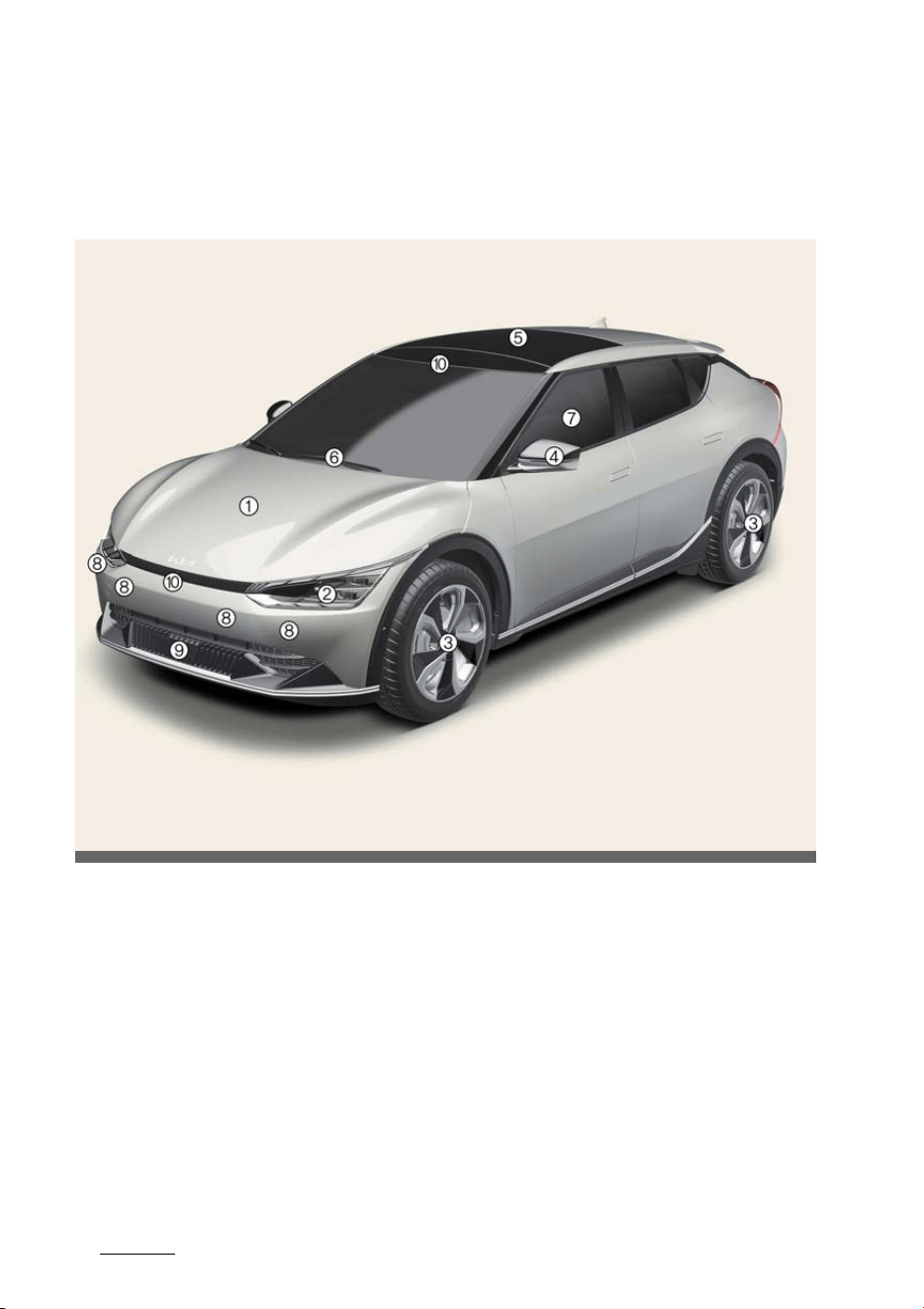
Your vehicle at a glance
23
Exterior overview
Your vehicle at a glance
Exterior overview
Front view
OCV011001L
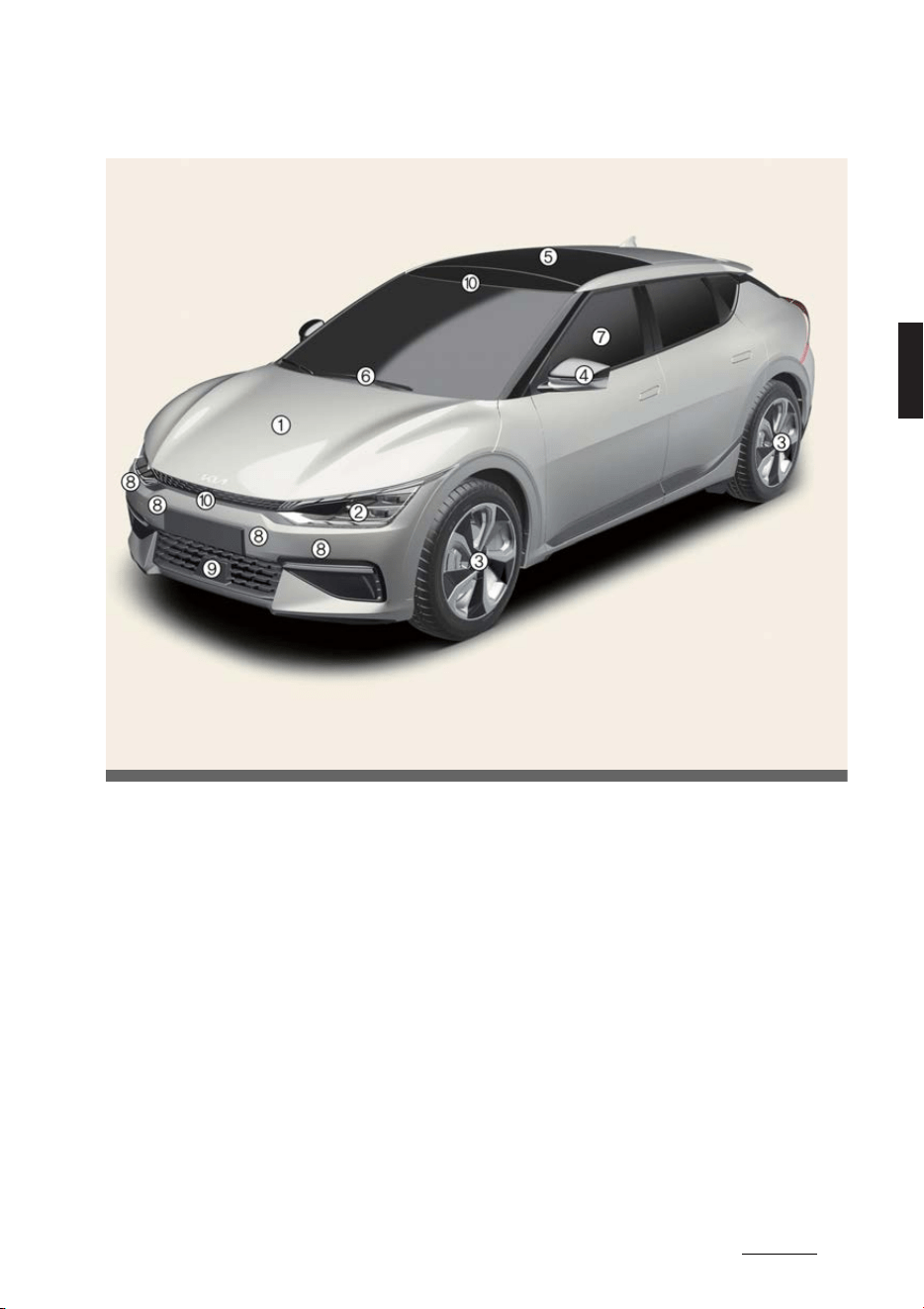
3
3
3
Your vehicle at a glance Exterior overview
Front view (GT-Line)
OCV012005L
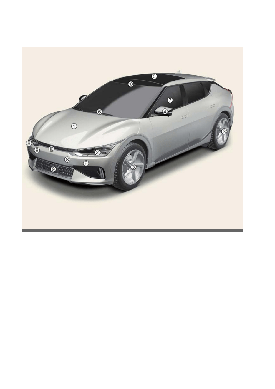
Your vehicle at a glance
43
Exterior overview
Front view (GT)
* The actual features in your vehicle may not necessarily be available due to the
selected options or regions.
1. Hood 5-32
2. Head lamp 5-61, 8-34
3. Wheel and tire 8-15, 9-6
4. Outside rear view mirror 5-42
5. Wide sunroof 5-36
6. Front windshield wiper blades 5-68, 8-12
7. Windows 5-30
8. Front ultrasonic sensor 6-154, 6-166
9. Front radar 6-43
10.Front view camera 6-43
OCVGT012001L
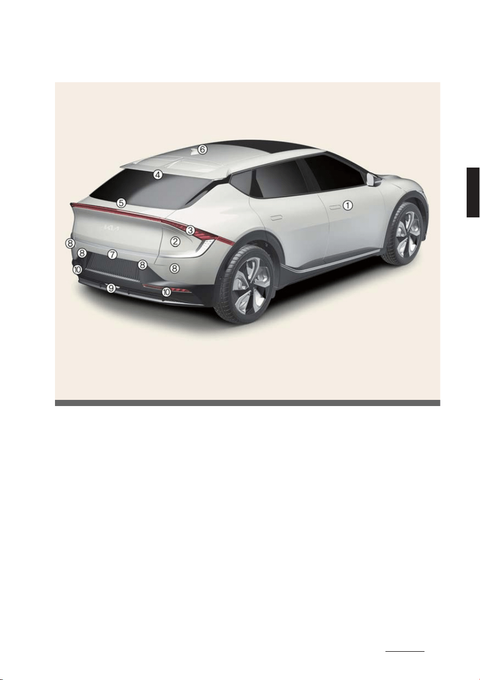
5
3
3
Your vehicle at a glance Exterior overview
Rear view
OCV011002L
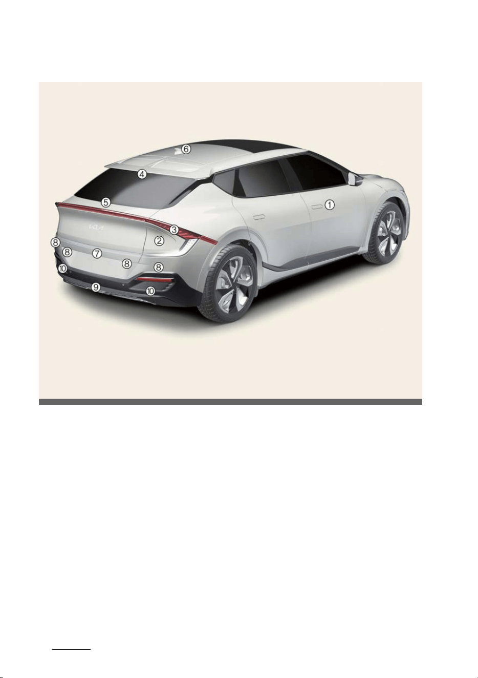
Your vehicle at a glance
63
Exterior overview
Rear view (GT-Line)
OCV012006L
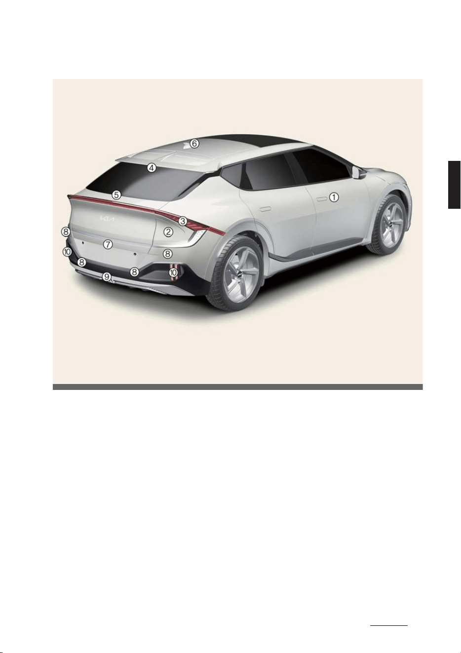
7
3
3
Your vehicle at a glance Exterior overview
Rear view (GT)
* The actual features in your vehicle may not necessarily be available due to the
selected options or regions.
1. Doors 5-11
2. Charging door 5-34
3. Rear combination lamp 8-35
4. High mounted stop lamp 8-35
5. Tailgate 5-21
6. Antenna 5-95
7. Wide-rear view camera 6-136, 6-138
8. Rear ultrasonic sensor 6-150, 6-166
9. Backup lamp 8-35
10.Rear fog lamp 8-35
OCVGT012002L
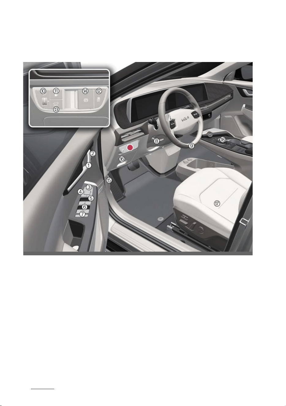
Your vehicle at a glance
83
Interior overview
Interior overview
Left-hand drive
OCV011003L
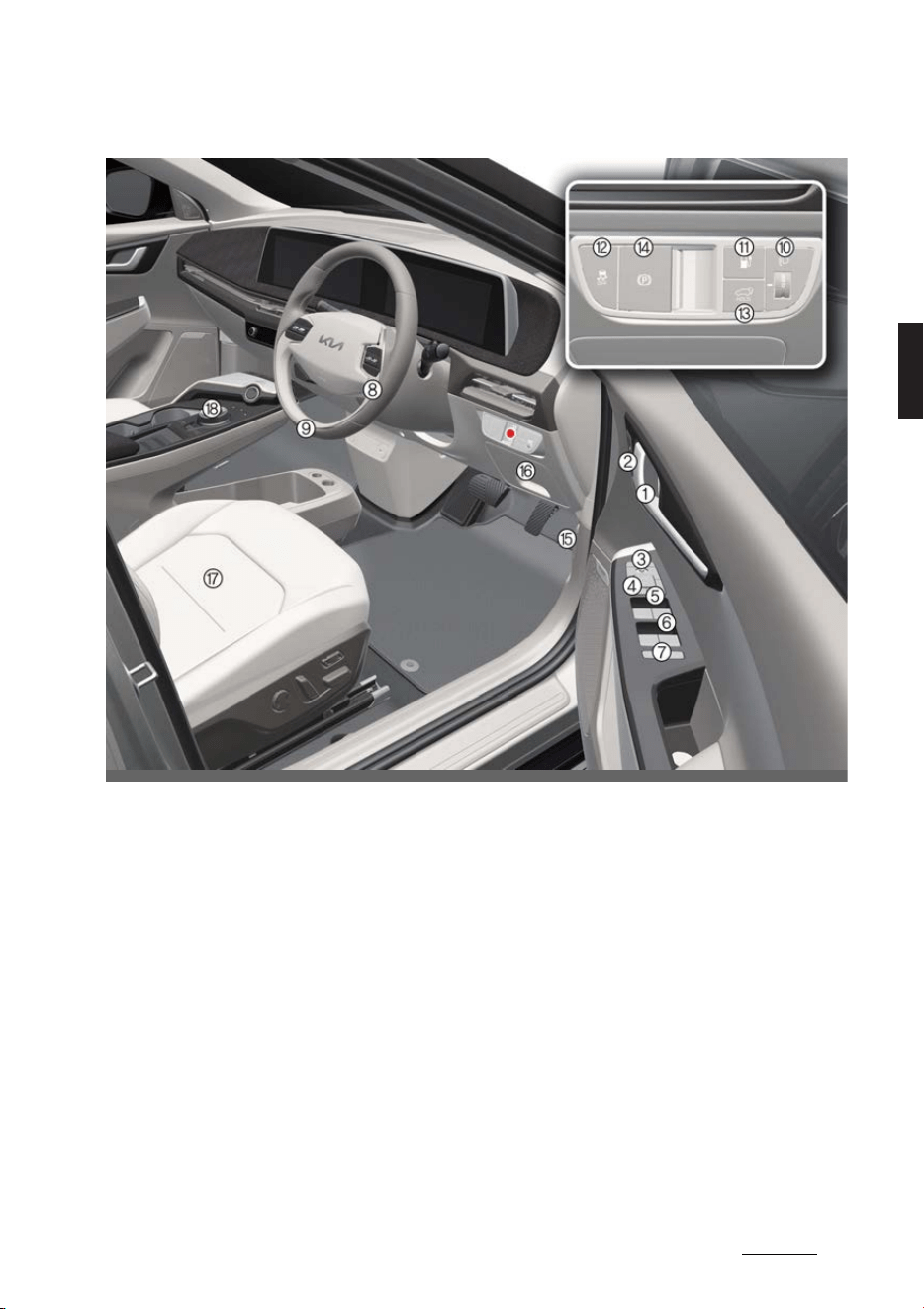
9
3
3
Your vehicle at a glance Interior overview
Right-hand drive
* The actual features in your vehicle may not necessarily be available due to the
selected options or regions.
1. Inside door handle 5-13
2. Driver position memory system (Except for GT) 5-19
3. Outside rearview mirror folding switch 5-42
4. Outside rearview mirror control switch 5-42
5. Central door lock/unlock switch 5-13
6. Power window switches 5-30
7. Power window lock/Electronic power child safety lock button 5-16, 5-30
8. Steering wheel tilt/telescopic lever 5-39
9. Steering wheel 5-39
10.Headlamp leveling adjustment switch 5-67
11.Charging door open/close button 5-34
12.ESC OFF button 6-30
13.Power tailgate open/close button 5-21
OCV012003R

Your vehicle at a glance
103
Interior overview
14.EPB switch 6-24
15.Hood release lever 5-32
16.Instrument panel fuse 8-23
17.Seat 4-3
18.Reduction gear (shifter dial) 6-10
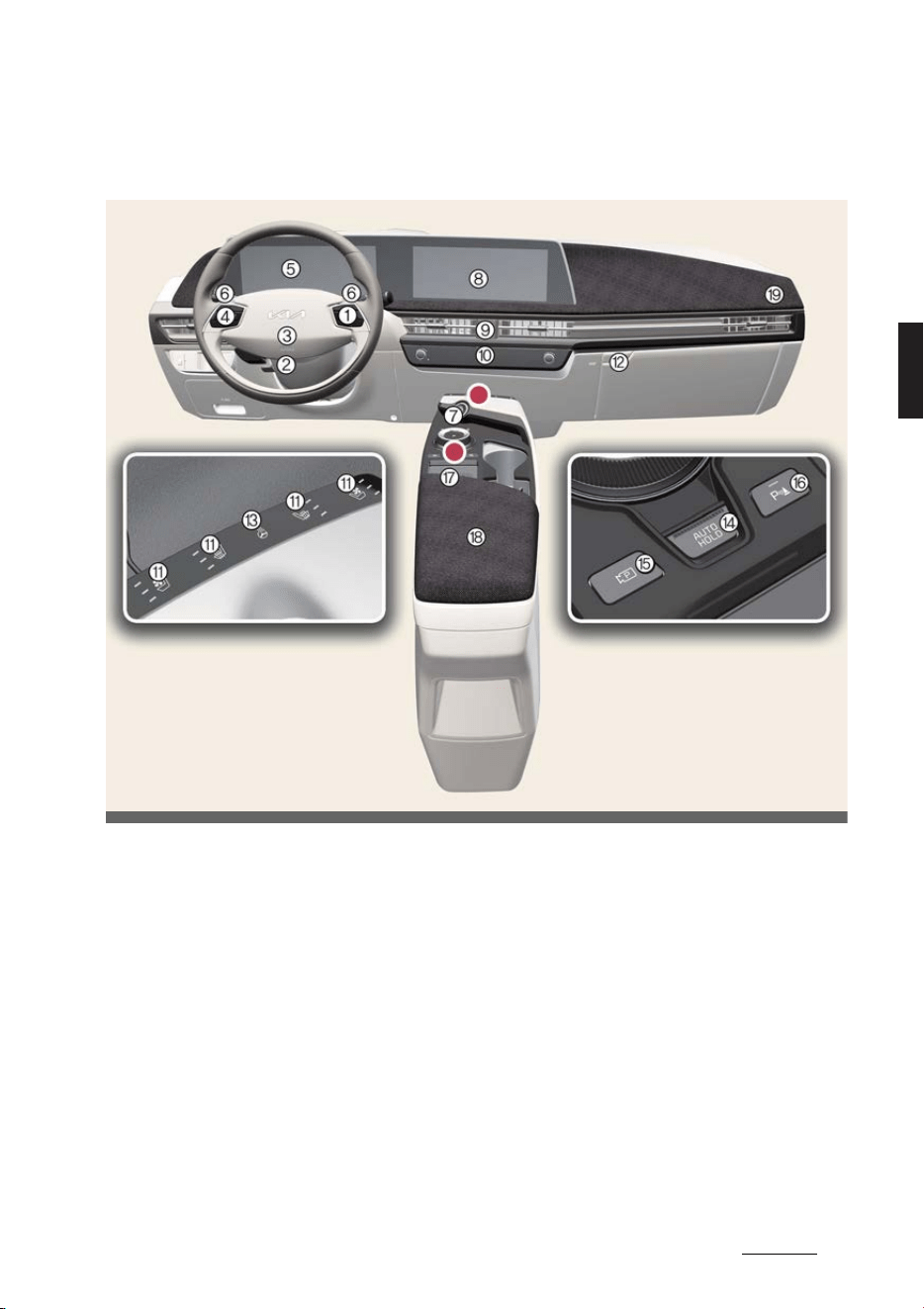
11
3
3
Your vehicle at a glance Instrument panel overview
Instrument panel overview
Left-hand drive
OCV011004L_2
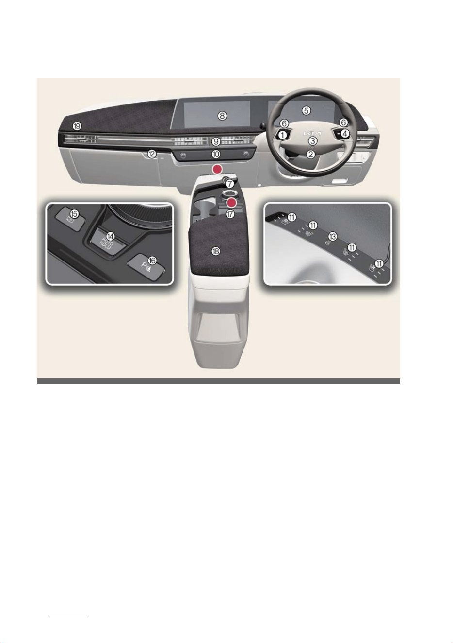
Your vehicle at a glance
123
Instrument panel overview
Right-hand drive
* The actual features in your vehicle may not necessarily be available due to the
selected options or regions.
1. Audio remote control button 5-95
2. Driver's front air bag 4-36
3. Horn 5-40
4. Driving Assist button 6-101, 6-104
5. Instrument cluster 5-45
6. Light control/turn signals lever Wiper and washer control lever 5-61, 5-68
7. EV button 6-8
8. Infotainment system 5-94
9. Hazard warning flasher switch 7-3
10.Infotainment/climate switchable controller 5-94
11.Front seat warmer and air ventilation seat button 5-88
12.Glove box 5-85
13.Steering wheel heater button 5-39
OCV011004R_2

13
3
3
Your vehicle at a glance Instrument panel overview
14.AUTO HOLD button 6-28
15.Parking/View button 6-136, 6-138, 6-166
16.Parking Safety button 6-154, 6-166
17.Wireless charging system 5-92
18.Center console storage box 5-85
19.Passenger's front air bag 4-36
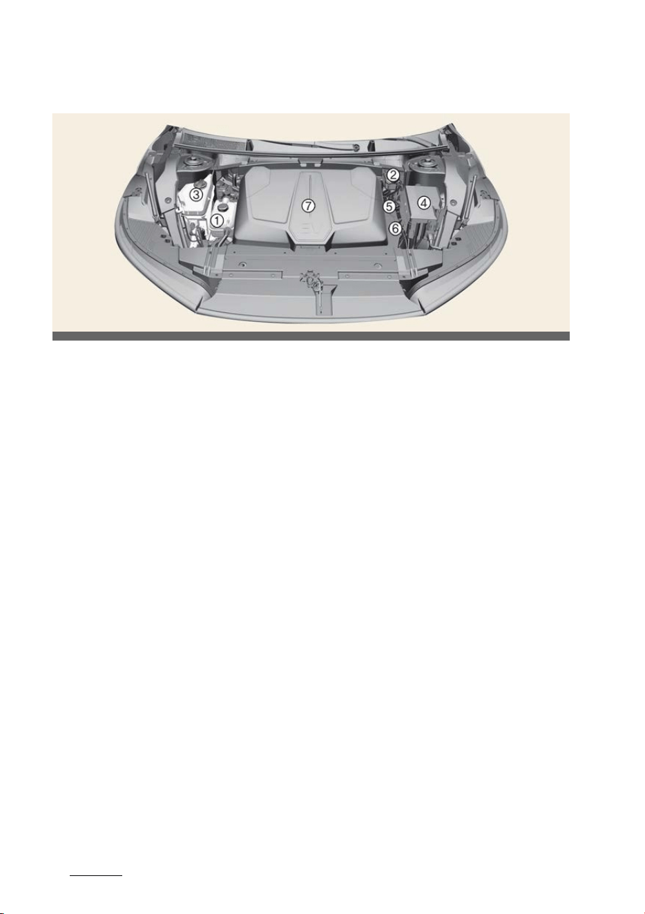
Your vehicle at a glance
143
Motor room compartment
Motor room compartment
* The actual motor compartment in the vehicle may differ from the illustration.
1. Coolant reservoir 8-9
2. Brake fluid reservoir 8-9
* This part is located on the opposite side for Right-hand drive vehicle.
3. Windshield washer fluid reservoir 8-10
4. Fuse box 8-22
5. Negative battery terminal (-) 8-13
6. Positive battery terminal (+) 8-13
7. Front trunk 5-33
OCV071001L

4Safety features of your vehicle
Safety features of your vehicle
Seat.................................................................................................. 4-3
僅 Infotainment system.......................................................................................4-4
僅 Adjusting the front seat.................................................................................4-4
僅 Seatback pocket...............................................................................................4-6
僅 Adjusting the rear seat ..................................................................................4-8
Headrest .......................................................................................4-10
僅 Adjusting the headrest ................................................................................4-10
僅 Removing/reinstalling the headrest .......................................................4-11
Armrest ......................................................................................... 4-12
僅 Adjusting the armrest................................................................................... 4-12
僅 Carrying long/narrow cargo...................................................................... 4-12
Seat belts ...................................................................................... 4-13
僅 Seat belt restraint system...........................................................................4-14
僅 Seat belt precautions....................................................................................4-18
僅 Care of seat belts .......................................................................................... 4-20
Child restraint system (CRS) ...................................................... 4-21
僅 Our recommendation: Children always in the rear ........................ 4-21
僅 Selecting a Child Restraint System (CRS) ...........................................4-22
僅 Installing a Child Restraint System (CRS)............................................4-23
ISOFIX anchorage and top-tether anchorage (ISOFIX Anchor-
age System) for children ............................................................4-24
僅 Securing a Child Restraint System with the "ISOFIX Anchorage"
system ................................................................................................................ 4-24
僅 Securing a Child Restraint System with the "Top-tether Anchorage"
system .................................................................................................................4-25
僅 Securing a Child Restraint System with a lap/shoulder belt.......4-25
僅 Suitability of each seating position for belted & ISOFIX Child
Restraint Systems (CRS) according to UN regulations (Information
for use by vehicle users and CRS manufacturers) ..........................4-27
僅 Recommended CRS for Vehicle according to UN regulations ..4-28

4 Safety features of your vehicle
Air bag – supplemental restraint system ................................ 4-29
僅 Air bag warning and indicator light.......................................................4-32
僅 SRS components and functions..............................................................4-34
僅 Driver's and passenger's front air bags ...............................................4-36
僅 Side air bag and front center air bag....................................................4-38
僅 Curtain air bag ................................................................................................4-39
僅 Air bag collision sensors ............................................................................. 4-41
僅 Air bag inflation conditions........................................................................4-42
僅 Air bag non-inflation conditions..............................................................4-43
僅 SRS care............................................................................................................ 4-45
僅 Additional safety precautions.................................................................. 4-45
僅 Adding equipment to or modifying your air bag-equipped
vehicle................................................................................................................. 4-46
僅 Air bag warning labels................................................................................ 4-46
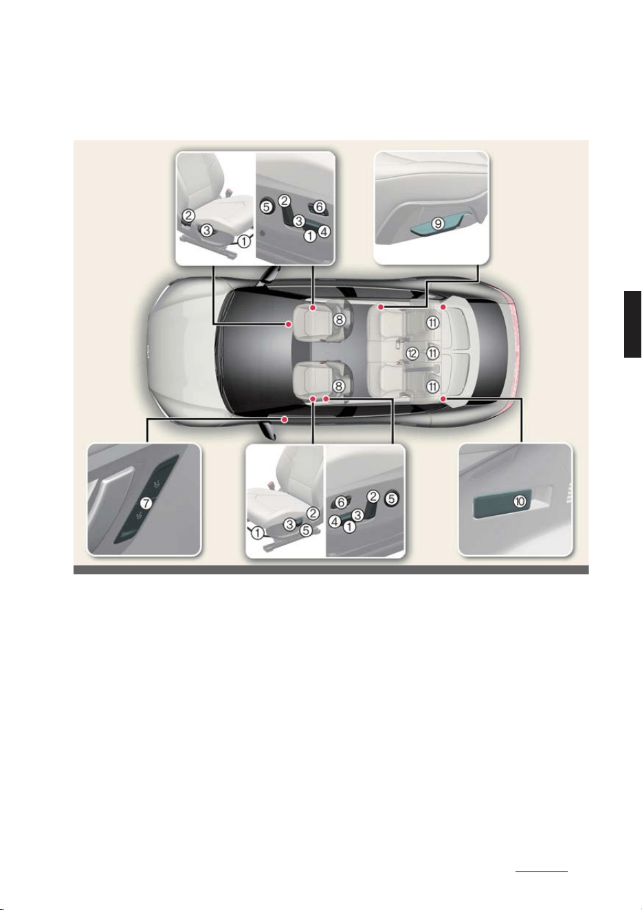
3
4
4
Safety features of your vehicle Seat
Safety features of your vehicle
Seat
* The actual features in your vehicle may not necessarily be available due to the
selected options or regions.
* The picture above is based on LHD vehicle. For RHD vehicle, the operation of front
seat are located on the opposite side.
Front seat
1
Forward and backward
2
Seatback angle
3
Seat cushion height
4
Seat cushion tilt
5
Lumbar support
6
Relaxion comfort seat
7
Driver position memory system
8
Headrest
2nd-row seat
9
Seatback angle/folding
10
Seatback folding
11
Headrest
12
Armrest
OCV031100L_7
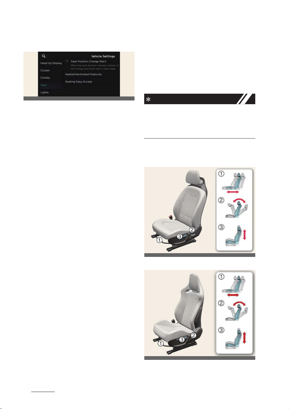
Safety features of your vehicle
44
Seat
Infotainment system
Select
Settings
→
Vehicle
→
Seat
from
the Settings menu in the infotainment
system screen, you may use various
convenience functions.
僅
Seat position change alert
: When the
seat position changes, details of the
change are shown with a seat image.
僅
Heating/Ventilation
-
Auto. Controls That Use Climate
Control Settings
(for driver's seat):
The seat temperature is automati
-
cally controlled.
僅
Seat Easy Access
-
Steering easy access
: Moves the
steering wheel when the driver
enters or leaves the vehicle.
-
Easy seat (fwd/bwd) access
(
Nor
-
mal
/
Extended
/
Off
) the seat auto
-
matically moves when the driver
enters or leaves the vehicle may be
selected.
For detailed information, refer to Navi
-
gation Quick Reference Guide.
* The information provided may differ
according to which functions are
applicable to your vehicle.
Adjusting the front seat
Operation
僅 The seat can be adjusted using the
control levers located on the outside
of the seat cushion.
INFORMATION
Adjust the seat before driving, and make
sure the seat is locked securely by trying
to move without using the lever. If the
seat moves, it is not locked properly.
Manual seat
Type A
Type B
1
Forward/backward
2
Seatback angle
OCV041523L
OCV031002L
OCVGT032002L
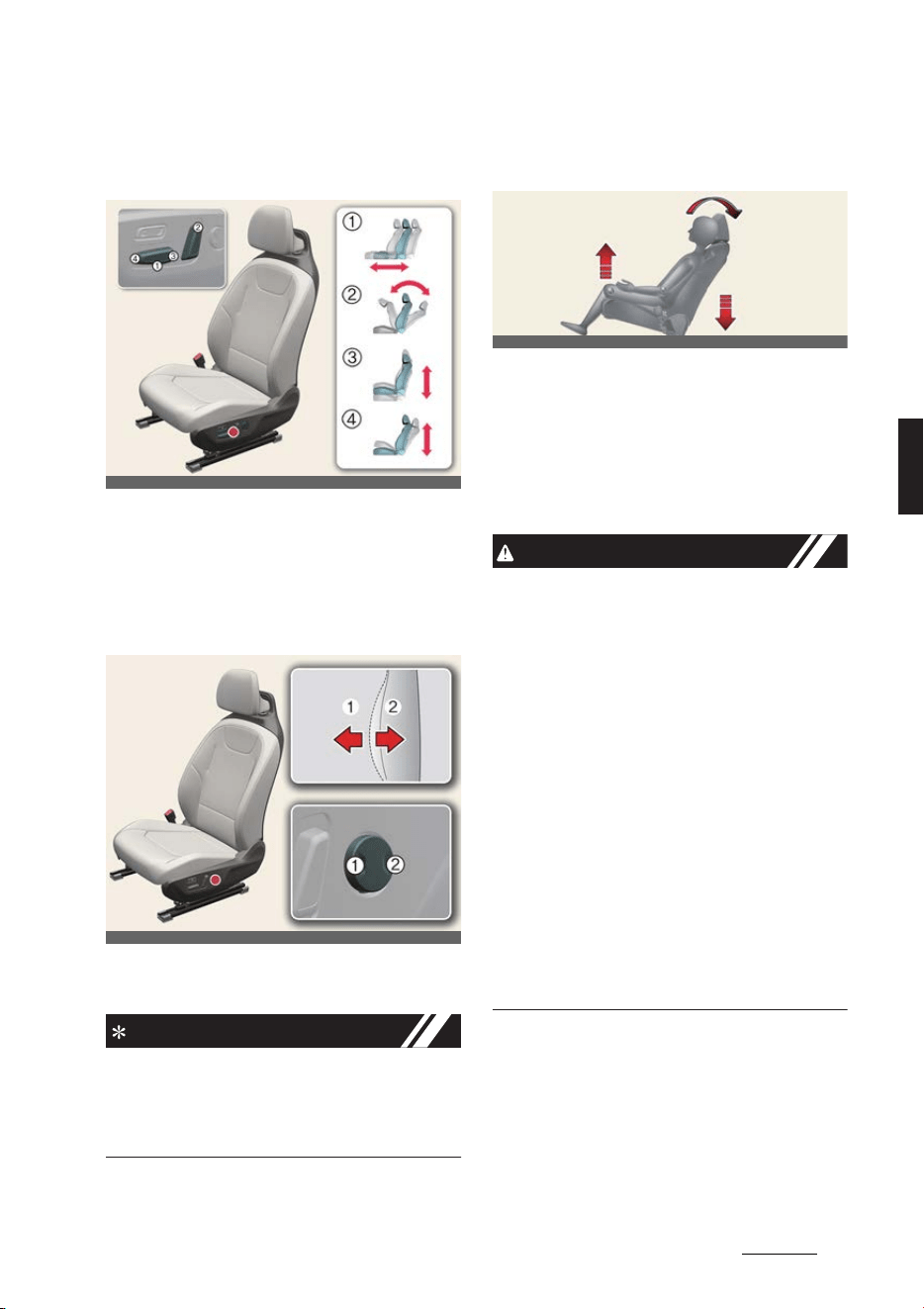
5
4
4
Safety features of your vehicle Seat
3
Cushion height
Power seat (if equipped)
1
Forward/backward
2
Seatback angle
3
Cushion height
4
Cushion tilt
Lumbar support (if equipped)
1
Increase support
2
Decrease support
NOTICE
Do not continue to operate the lumbar
support when the lumbar support pro
-
vides its maximum support. Damage to
the lumbar support motor could occur.
Relaxion comfort seat (for front
seats) (if equipped)
Relaxion comfort seats distribute body
pressure and concentrated weight on
specific body parts that occur while sit
-
ting in the same position for a long
period of time. The seat relieves fatigue
and discomfort by providing the optimal
sit position.
CAUTION
Take the following precautions when
using the relaxion comfort seat:
僅 Do not use the relaxion comfort seat
while the vehicle is moving. Using the
comfort seat could increase the risk of
injuries in the event of a collision or
sudden stop.
僅 Do not use the relaxion comfort seat
while the vehicle is moving. The shoul
-
der belt may not adhere to your chest
firmly.
僅 Do not use the relaxion comfort seat
when the luggage or other objects are
placed at the rear seat.
僅 Do not use the relaxion comfort seat
when the rear seats are not in the
rearmost position and upright.
OCV031003L_2
OCV031004L_2
OCV031060L
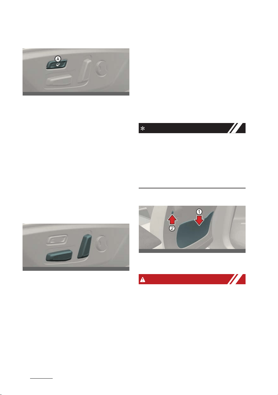
Safety features of your vehicle
64
Seat
Operating relaxion comfort seat
Operation
1. Press the rear portion of the switch (A)
more than 1 second.
2. An alarm appears on the infotainment
screen.
3. Press the switch (A) again for more
than 1 seconds within 5 seconds.
4. If the seat adjustment switch (reclin
-
ing, cushion height) is operated
during relaxion comfort seat operat
-
ing, the operation will stop.
5. After the operation is complete, it can
be adjusted more using the seat
adjustment switch for a more com
-
fortable posture.
Operating condition(s)
僅 Driver's seat
- Power button is ACC, ON, START/
RUN position
- P (Park) gear position is selected.
- Driver's side rear seat seatbelt is
not fastened
僅 Passenger's seat
- Power button is ACC, ON, START/
RUN position
- Passenger's side rear seat seatbelt
is not fastened
Returning relaxion comfort seat
Operation
If you press the front portion of the
switch (A) more than 1 second while the
seat is in the relaxion comfort seat posi
-
tion, the seat return backs to the original
position.
NOTICE
When relaxion comfort seat cannot be
operated, try to reset Integrated Memory
System. If relaxion comfort seat does not
operate even after Integrated Memory
System is reset, it is recommended that
you contact an authorized Kia dealer/
service partner.
Seatback pocket (if equipped)
1
Seatback pocket
2
USB charger
WARNING
僅 Loose objects in the driver's foot area
could interfere with the operation of
the foot pedals, possibly causing an
accident.
僅 When you return the seatback to its
upright position, hold the seatback
and return it slowly and be sure there
are no other occupants around the
seat. If the seatback is returned with
-
out being held and controlled, the
back of the seat could spring forward
OCV031005L
OCV031006L
OCV031101L

7
4
4
Safety features of your vehicle Seat
resulting in accidental injury to a per
-
son struck by the seatback.
僅 Riding in a vehicle with the seatback
reclined could lead to serious or fatal
injury in an accident.
僅 If a seat is reclined during an accident,
the occupant's hips may slide under
the lap portion of the seatbelt, apply
-
ing great force to the unprotected
abdomen. Serious or fatal internal
injuries could result. The driver must
advise the passenger to keep the
seatback in an upright position when
-
ever the vehicle is in motion.
僅 Do not use a sitting cushion that
reduces friction between the seat and
passenger. The passenger's hips may
slide under the lap portion of the seat
belt during an accident or a sudden
stop. Serious or fatal internal injuries
could result because the seat belt
can't operate normally.
僅 Never attempt to adjust any seat
while the vehicle is moving. This could
result in loss of control, and an acci
-
dent causing death, serious injury, or
property damage.
僅 Do not allow anything to interfere with
the normal position of the seatback.
Storing items against a seatback or in
any other way interfering with proper
locking of a seatback could result in
serious or fatal injury in a sudden stop
or collision.
僅 Always drive and ride with your seat
-
back upright and the lap portion of
the seat belt snug and low across the
hips. This is the best position to pro
-
tect you in case of an accident.
僅 In order to avoid unnecessary and
perhaps severe air bag injuries,
always sit as far back as possible from
the steering wheel while maintaining
comfortable control of the vehicle. We
recommend that your chest is at least
250 mm (10 inches) away from the
steering wheel.
僅The rear seatback must be securely
latched. If not, passengers and objects
could be thrown forward resulting in
serious injury or death in the event of
a sudden stop or collision.
僅 Luggage and other cargo should be
laid flat in the cargo area. If objects
are large, heavy, or must be piled,
they must be secured. Under no cir
-
cumstances should cargo be piled
higher than the seatbacks. Failure to
follow these warnings could result in
serious injury or death in the event of
a sudden stop, collision or rollover.
僅 No passenger should ride in the cargo
area or sit or lie on folded seatbacks
while the vehicle is moving. All pas
-
sengers must be properly seated in
seats and restrained properly while
riding.
僅 When resetting the seatback to the
upright position, make sure it is
securely latched by pushing it forward
and backwards.
僅 After adjusting the seat, always check
that it is securely locked into place by
attempting to move the seat forward
or backward without using the lock
release lever. Sudden or unexpected
movement of the driver's seat could
cause you to lose control of the vehi
-
cle resulting in an accident.
僅 Do not adjust the seat while wearing
seat belts. Moving the seat cushion
forward may cause strong pressure
on the abdomen.
僅 Use extreme caution so that hands or
other objects are not caught in the
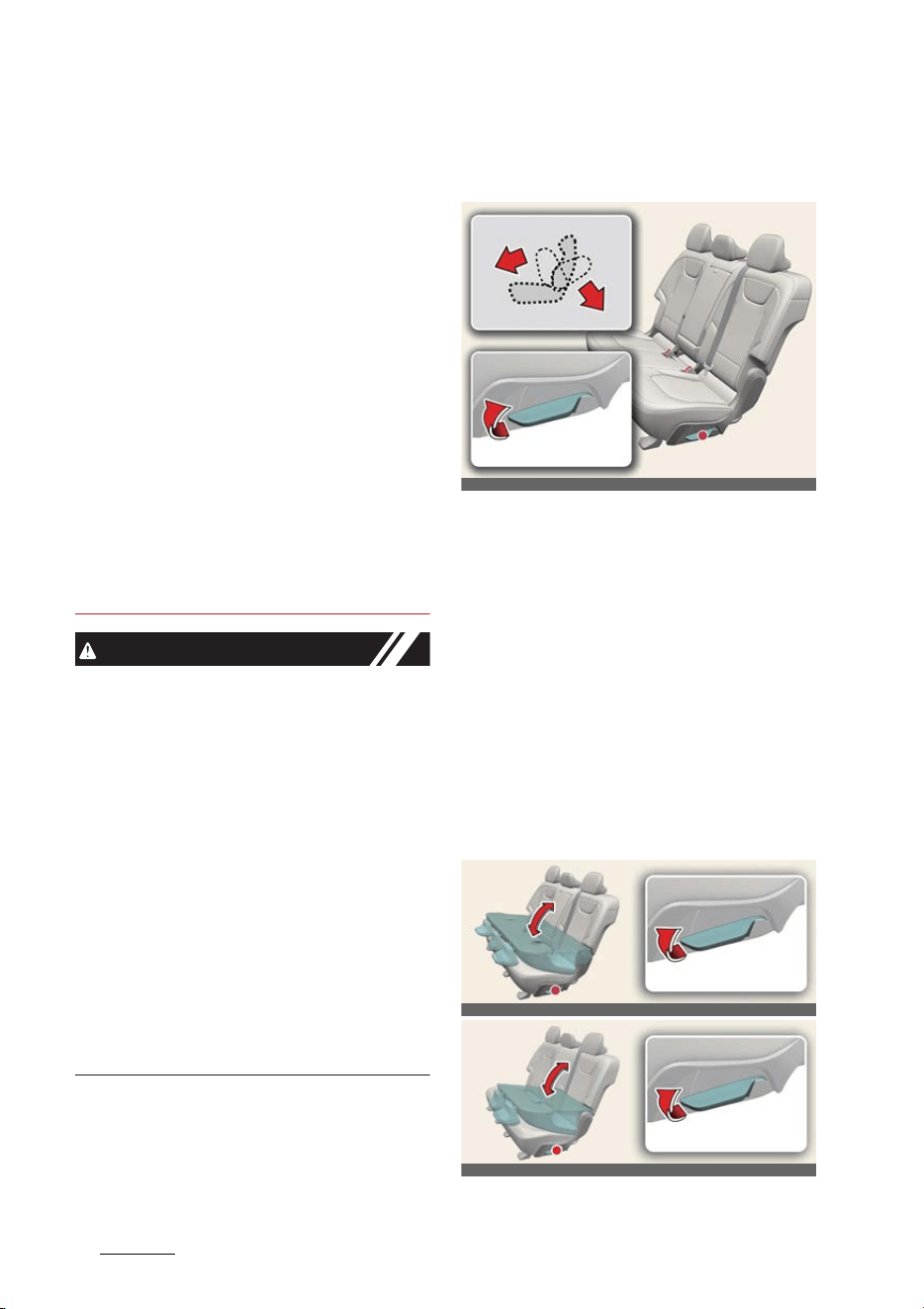
Safety features of your vehicle
84
Seat
seat mechanisms while the seat is
moving.
僅Do not put a cigarette lighter on the
floor or seat. When you operate the
seat, gas may gush out of the lighter
and cause fire.
僅 If there are occupants in the rear
seats, be careful while adjusting the
front seat position.
僅 Use extreme caution when picking
small objects trapped under the seats
or between the seat and the center
console. Your hands might be cut or
injured by the sharp edges of the seat
mechanism.
僅 The power seat is operable with the
EV button in OFF position. Therefore,
children should never be left unat
-
tended in the car.
CAUTION
僅 The power seat is driven by an electric
motor. Stop operating once the
adjustment is completed. Excessive
operation may damage the electrical
equipment.
僅 When in operation, the power seat
consumes a large amount of electrical
power. To prevent unnecessary
charging system drain, don't adjust
the power seat longer than necessary
while the vehicle is not running.
僅 Do not operate two or more power
seat control switches at the same
time. Doing so may result in power
seat motor or electrical component
malfunction.
Adjusting the rear seat
Adjusting rear seatback angle
Operation
1. Pull up the seatback recline lever.
2. Hold the lever and adjust the seat
-
back of the seat to the position you
desire.
僅 Release the lever and make sure
the seatback is locked in place.
(The lever MUST return to its origi
-
nal position for the seatback to
lock.)
Folding rear seatback
Type A
OCV031008L_2
OCV031009L
OCVGT032009L
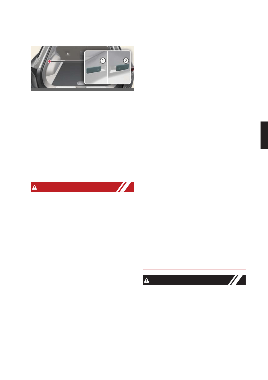
9
4
4
Safety features of your vehicle Seat
Type B
1
Left side seatback
僅 For type A, pull up the seatback
folding lever, then fold the seat
down.
僅 For type B, pull the seatback fold
-
ing lever (1) and (2).
2
Right side seatback
Operation
Insert the seat belt buckle/webbing in
the pocket/guide.
WARNING
僅 Never attempt to adjust while the
vehicle is moving or the rear seat is
occupied as the seat may suddenly
move and cause the passenger on the
seat to be injured.
僅 The purpose of the fold-down rear
seatbacks is to allow you to carry lon
-
ger objects that could not be accom
-
modated in the cargo area. Never
allow passengers to sit on top of the
folded down seatback while the vehi
-
cle is moving. This is not a proper
seating position and no seat belts are
available for use. This could result in
serious injury or death in case of an
accident or sudden stop. Objects car
-
ried on the folded down seatback
should not extend higher than the top
of the front seatbacks. This could
allow cargo to slide forward and
cause injury or damage during sud
-
den stops.
僅 Do not fold the rear seats. if passen
-
gers, pets or luggage are in the rear
seats. It may cause injury or damage
to passengers, pets or luggage.
僅 When you return the seatback to its
upright position, hold the seatback
and return it slowly. If the seatback is
returned without holding it, the back
of the seat could spring forward
resulting in injury caused by being
struck by the seatback.
僅 Cargo should always be secured to
prevent it from being thrown about
the vehicle in a collision and causing
injury to the vehicle occupants. Do not
place objects in the rear seats, since
they cannot be properly secured and
may hit the front seat occupants in a
collision.
僅 Make sure the EV button is in OFF
position, P (Park) gear position is
selected. and the parking brake is
securely applied whenever loading or
unloading cargo. Failure to take these
steps may allow the vehicle to move if
the shift lever is inadvertently moved
to another position.
僅 Never attempt to adjust while the
vehicle is moving or the rear seat is
occupied as the seat may suddenly
move and cause the passenger on the
seat to be injured.
CAUTION
僅 Do not allow your hands or fingers to
get caught in the seat mechanisms
while adjusting the seats.
僅 When returning the rear seatbacks to
the upright position, remember to
return the rear shoulder belts to their
proper position. Routing the seat belt
webbing through the rear seat belt
guides will help keep the belts from
OCV031010L_2
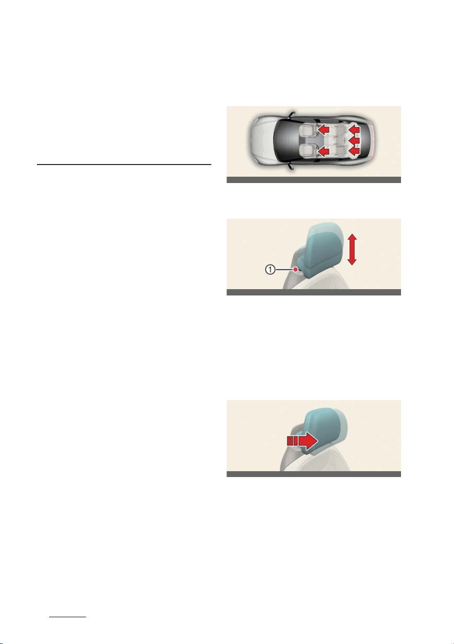
Safety features of your vehicle
104
Headrest
being trapped behind or under the
seats.
僅 When you fold the rear seatback,
insert the buckle in the pocket
between the rear seatback and cush
-
ion. Doing so can prevent the buckle
from being damaged by the rear seat
-
back.
Headrest
The seats are equipped with a headrest
for the occupant's safety and comfort.
Adjusting the headrest (if
equipped)
Operation
僅 Pull up the headrest to raise it.
僅 Push and hold the release button (1)
to lower the headrest.
Adjusting the headrest forward
and backward (if equipped)
Operation
僅 Pull the headrest fully forward and
release it.
OCV031011L
OCV031012L
OCV031013L
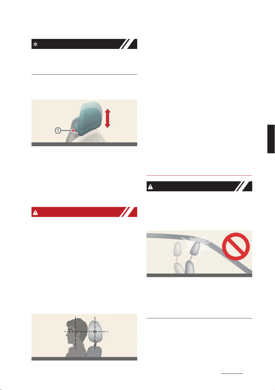
11
4
4
Safety features of your vehicle Headrest
INFORMATION
The headrest may be adjusted forward
to 3 different positions by pulling the
headrest forward.
Removing/reinstalling the head
-
rest (if equipped)
Operation
1. Recline the seatback.
2. Raise headrest as far as it can go.
3. Push and hold the release button (1)
while pulling the headrest up.
4. Install in the reverse order of removal.
WARNING
僅 For maximum effectiveness in case of
an accident, the headrest should be
adjusted so the middle of the head
-
rest in at the same height of the cen
-
ter of gravity of an occupant's head.
Generally, the center of gravity of
most people's head is similar with the
height of the top of their eyes. Also,
adjust the headrest as close to your
head as possible. For this reason, the
use of a cushion that holds the body
away from the seatback is not recom
-
mended.
僅 Do not operate the vehicle with the
headrests removed or reversed as
severe injury to the occupants may
occur in the event of an accident.
Headrests may provide protection
against neck injuries when properly
adjusted.
僅 Do not adjust the headrest position of
the driver's seat while the vehicle is in
motion.
僅 Make sure the headrest locks in posi
-
tion after adjusting it to properly pro
-
tect the occupants.
僅 Never allow anyone to ride in a seat
with the headrests removed.
僅 Always make sure the headrest locks
into position after reinstalling and
adjusting it properly.
CAUTION
僅 When there is no occupant in the rear
seats, adjust the height of the head
-
rest to the lowest position. The rear
seat headrest can reduce the visibility
of the rear area.
僅 If you recline the seatback towards
the front with the headrest and seat
cushion raised, the headrest may
come in contact with the sun visor or
other parts of the vehicle.
OCV031012L
OCV031014L
OCV031061L
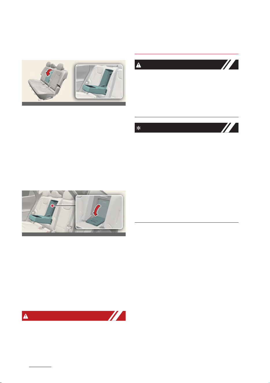
Safety features of your vehicle
124
Armrest
Armrest
Adjusting the armrest
Operation
僅 Pull the armrest forward from the
seatback.
僅 Slide the cover outwards to use the
cup holder.
僅 Slide the cover inwards to use the
storage area.
Carrying long/narrow cargo (if
equipped)
Additional cargo space is provided to
accommodate long/narrow cargo (skis,
poles, etc.) not able to fit properly in the
trunk when closed.
Operation
1. Pull the armrest down.
2. Pull the cover down while pushing the
release lever down.
WARNING
Do not put heavy or sharp objects in the
seatback pockets or inside the armrest
storage area. In an accident they could
come loose from the pocket and injure
vehicle occupants.
CAUTION
僅 Do not store small or heavy objects. It
might fly off and cause injuries.
僅 When cargo is loaded through the
rear passenger seats, ensure the
cargo is properly secured to prevent it
from moving while driving.
NOTICE
僅 Be careful when loading cargo
through the rear passenger seats to
prevent damage to the vehicle inte
-
rior.
僅 When both the armrest and the panel,
which is locates between the rear
seatback and the trunk, are folded
down, put back the panel first before
folding back the armrest. If not, the
panel knobs and the armrest knobs
may interfere with each other and get
damaged.
OCV031015L
OCV031016L

13
4
4
Safety features of your vehicle Seat belts
Seat belts
Seat belts are designed to bear upon the
bony structure of the body, and should
be worn low across the front of the pel
-
vis, chest and shoulders.
WARNING
僅 For maximum restraint system pro
-
tection, the seat belts must always be
used whenever the car is moving.
僅 Seat belts are most effective when
seatbacks are in the upright position.
僅 Children age 13 and younger must
always be properly restrained in the
rear seat. Never allow children to ride
in the front passenger seat. If a child
over 13 must be seated in the front
seat, he/she must be properly belted
and the seat should be moved as far
back as possible.
僅 Never wear the shoulder belt under
your arm or behind your back. An
improperly positioned shoulder belt
can cause serious injuries in a crash.
The shoulder belt should be posi
-
tioned midway over your shoulder
across your collarbone.
僅 Never wear a seat belt over fragile
objects. If there is a sudden stop or
impact, the seat belt can damage it.
僅 Avoid wearing twisted seat belts. A
twisted belt can't do its job as well. In a
collision, it could even cut into you. Be
sure the belt webbing is straight and
not twisted.
僅 Be careful not to damage the belt
webbing or hardware. If the belt web
-
bing or hardware is damaged, replace
it.
僅 Seat belts are designed to bear upon
the bony structure of the body, and
should be worn low across the front of
the pelvis or the pelvis, chest and
shoulders, as applicable; wearing the
lap section of the belt across the
abdominal area must be avoided. Seat
belts should be adjusted as firmly as
possible, consistent with comfort, to
provide the protection for which they
have been designed. A slack belt will
greatly reduce the protection afforded
to the wearer. Care should be taken to
avoid contamination of the webbing
with polishes, oils and chemicals, and
particularly battery acid. Cleaning
may safely be carried out using mild
soap and water. The belt should be
replaced if webbing becomes frayed,
contaminated or damaged. It is essen
-
tial to replace the entire assembly
after it has been worn in a severe
impact even if damage to the assem
-
bly is not obvious. Belts should not be
worn with straps twisted. Each belt
assembly must only be used by one
occupant; it is dangerous to put a belt
around a child being carried on the
occupant's lap.
僅 No modifications or additions should
be made by the user which will either
prevent the seat belt adjusting
devices from operating to remove
slack, or prevent the seat belt assem
-
bly from being adjusted to remove
slack.
僅 When you fasten the seat belt, be
careful not to latch the seat belt in
buckles of other seat. It's very danger
-
ous and you may not be protected by
the seat belt properly.
僅 Do not unfasten the seat belt and do
not fasten and unfasten the seat belt
repeatedly while driving. This could
result in loss of control, and an acci
-
dent causing death, serious injury, or
property damage.
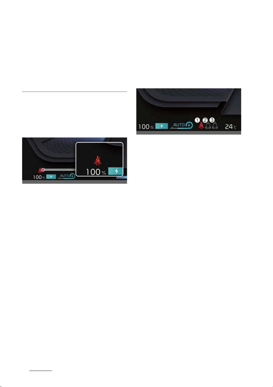
Safety features of your vehicle
144
Seat belts
僅 When fastening the seat belt, make
sure that the seat belt does not pass
over objects that are hard or can
break easily.
僅 Make sure there is nothing in the
buckle. The seat belt may not be fas
-
tened securely.
Seat belt restraint system
Seat belt warning light
Front seat belt warning light (if
equipped)
Operating condition(s)
僅 When the vehicle is running
- The front seat belt warning light will
illuminate for approximately 3~6
seconds.
僅 When the front seat belt is unfastened
- For driver's seat, the front seat belt
warning chime will sound for
approximately 5 seconds. (if
equipped)
- The front seat belt warning light will
stay illuminated. (if equipped)
僅 When the front seat belt is unfastened
during driving and the vehicle speed
is under approximately 20 km/h (12
mph)
- The front seat belt warning light will
illuminate
僅 When the vehicle speed is over
approximately 20 km/h (12 mph)
- The warning chime will sound for
approximately 100 seconds
- The front seat belt warning light will
blink.
Rear passenger seat belt warn
-
ing lights (if equipped)
僅 2nd-row seat: (1) Driver's side, (2) Cen
-
ter, (3) Passenger's side
Operating condition(s)
For Europe
僅 When the vehicle is running
- Rear passenger's seat belt warning
light will illuminate for approxi
-
mately 6 seconds.
僅 When the seat belt is unfastened
during driving and the vehicle speed
is under approximately 20 km/h (12
mph)
- Rear passenger's seat belt warning
light will stay illuminated.
僅 When the vehicle speed is over
approximately 20 km/h (12 mph)
- Rear passenger's seat belt warning
chime will sound for approximately
35 seconds
- Rear passenger's seat belt warning
light will blink.
僅 When the vehicle is driven without the
seat belt fastened, or the driver has
unfastened the seat belt when the
vehicle speed is over approximately
20 km/h (12 mph)
OCV031017
OCV031018L
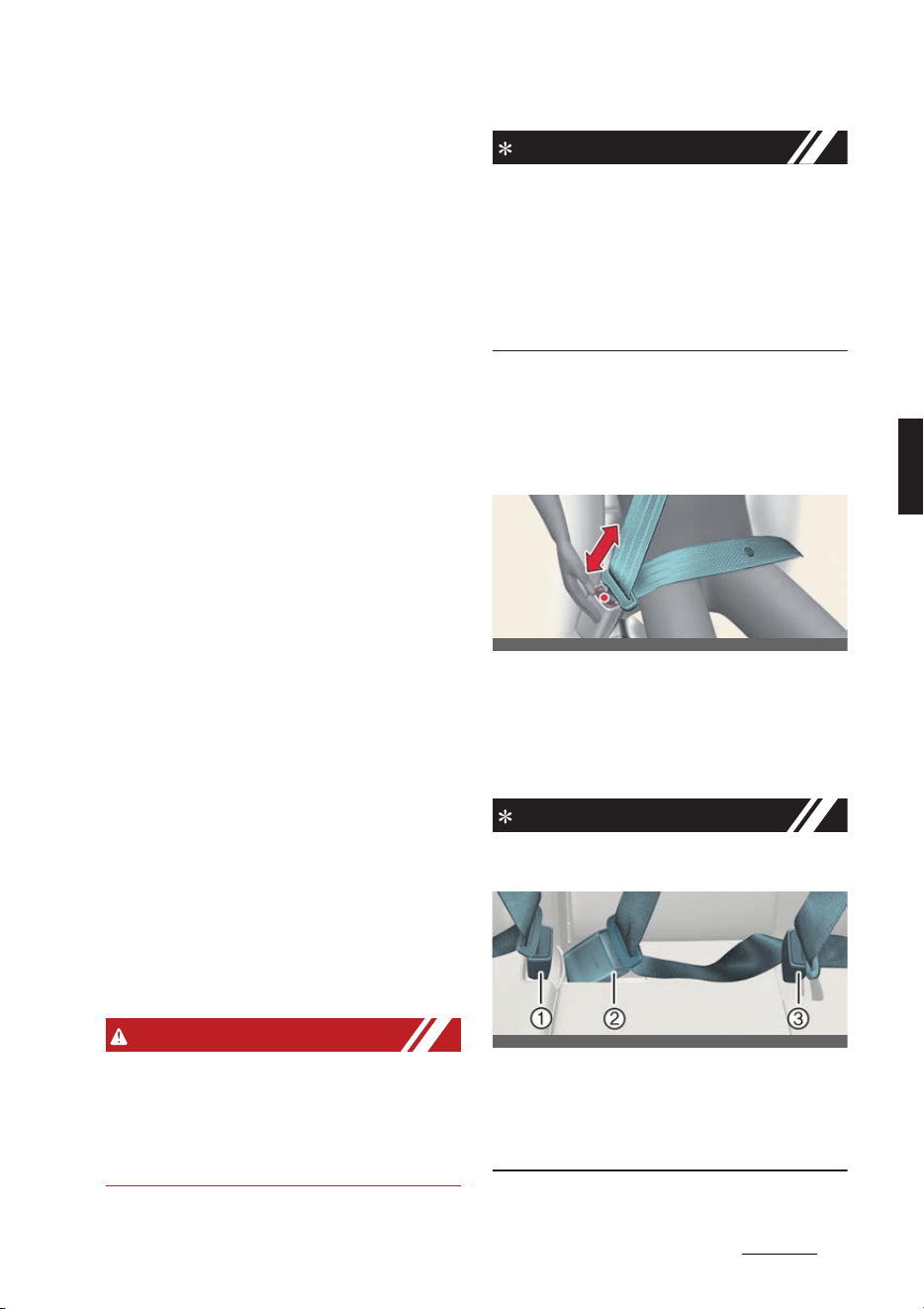
15
4
4
Safety features of your vehicle Seat belts
- Rear passenger's seat belt warning
chime will sound for approximately
35 seconds
- Rear passenger's seat belt warning
light will blink.
Except Europe
僅 When the vehicle is running
- Rear passenger's seat belt warning
light will illuminate for approxi
-
mately 6 seconds.
僅 When the seat belt is unfastened
during driving and the vehicle speed
is under approximately 20 km/h (12
mph)
- Rear passenger's seat belt warning
light will blink for approximately 70
seconds.
僅 When the vehicle speed is over
approximately 20 km/h (12 mph)
- Rear passenger's seat belt warning
chime will sound for approximately
35 seconds
- Rear passenger's seat belt warning
light will blink.
Non-operating condition(s)
僅 When the rear door is opened or
closed, and the vehicle speed is under
10 km/h (6 mph)
- Seat belt warning light and the seat
belt warning chime will not work
even if the vehicle speed is over
approximately 20 km/h (12 mph).
WARNING
Riding in an improper position adversely
affects the front seat belt warning sys
-
tem. It is important for the driver to
instruct the passenger to properly be
seated as instructed in this manual.
NOTICE
僅 Although the front passenger seat is
not occupied, the seat belt warning
light will blink or illuminate for 6 sec
-
onds.
僅 The front passenger's seat belt warn
-
ing may operate when luggage is
placed.
Seat belt - 3-point system with
emergency locking retractor
Fastening/unfastening the seat
belt
Operation
僅 Insert the metal tab into the buckle.
僅 Press the release button in the locking
buckle.
INFORMATION
僅 There will be an audible "click" when
the tab locks into the buckle.
1
Rear right seat belt fastening buckle
2
Rear center seat belt fastening buckle
(with the "
CENTER
" mark)
3
Rear left seat belt fastening buckle
OCV031019L
OCV031020L
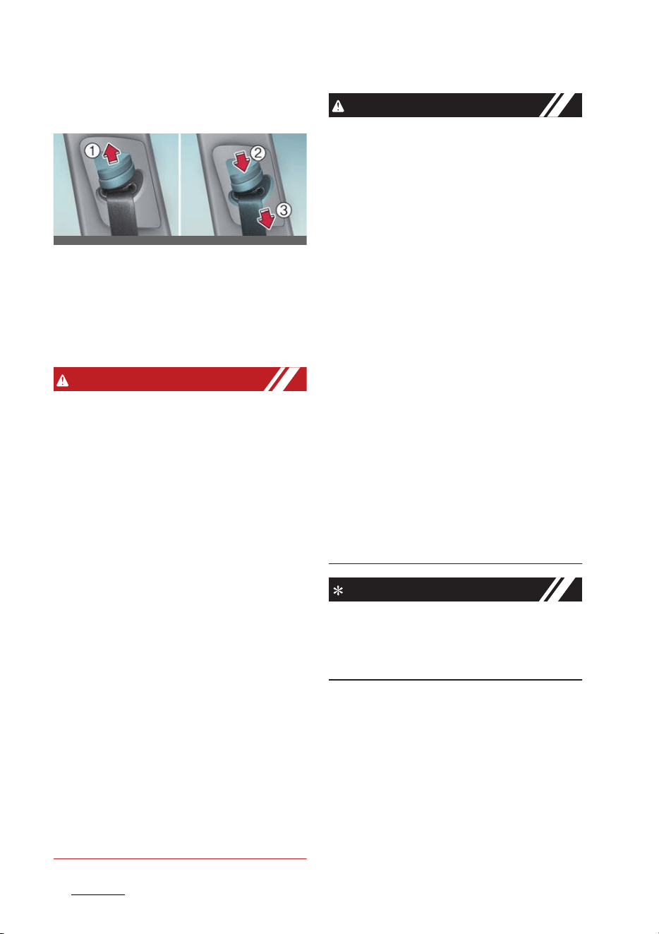
Safety features of your vehicle
164
Seat belts
Adjusting the height of the shoul
-
der belt
Operation
僅 Pull the height adjuster up (1).
僅 Press the height adjuster button (2)
and push the height adjuster down
(3).
WARNING
僅 You should place the lap belt portion
as low as possible and snugly across
your hips, not on your waist. If the lap
belt is located too high on your waist,
it may increase the chance of injury in
the event of a collision. Both arms
should not be under or over the belt.
Rather, one should be over and the
other under, as shown in the illustra
-
tion. Never wear the seat belt under
the arm near the door.
僅 Prior to fastening the rear seat belts,
ensure the latch matches the seat belt
buckle. Forcefully fastening the left or
right seat belt to the center buckle can
result in an improper fastening sce
-
nario that will not protect you in an
accident.
僅 After a collision, the seat belt system
should be inspected to ensure it is
operating normally. Replace any belts
that are not functioning appropriately.
僅 Verify the shoulder belt anchor is
locked into position at the appropriate
height. Never position the shoulder
belt across your neck or face.
CAUTION
僅 Do NOT fold down the left portion of
the rear seatback when the rear cen
-
ter seat belt is buckled. ALWAYS
UNBUCKLE the rear center seat belt
before folding down the left portion of
the rear seatback. If the rear center
seat belt is buckled when the left por
-
tion of the rear seatback is folded
down, distortion and damage to the
top portion of the seatback and seat
belt garnish may result, causing the
seatback to lock into the folded down
position.
僅 Do not force to lock the left or right
seat belt into the center seat belt
buckle. Make sure to lock the rear
center seat belt into the center seat
belt buckle. If not, the improperly fas
-
tened seat belt will not be able to pro
-
vide protection.
僅 When pulling out to wear the seat belt,
the tongue should be slowly pulled
out of the seat belt guide so that the
seat belt guide does not come off the
trim.
NOTICE
If you are not able to pull out the seat
belt from the retractor, firmly pull the
belt out and release it. Then you will be
able to pull the belt out smoothly.
Seat belt pretensioner
Your vehicle is equipped with front
driver and passenger, and rear passen
-
gers' (if equipped) Seat belt pretension
-
ers.
OCV031021L_2
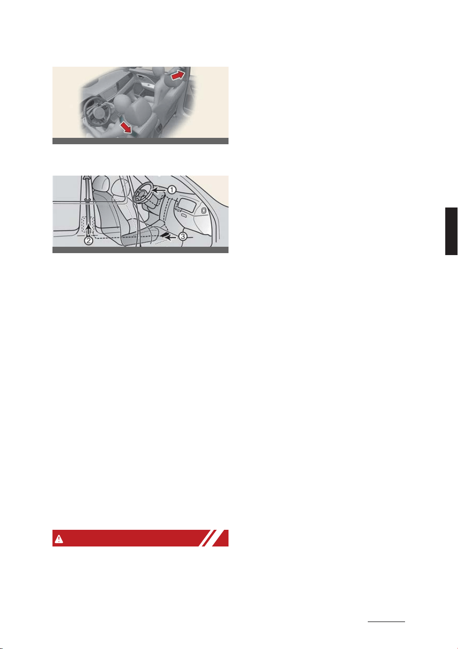
17
4
4
Safety features of your vehicle Seat belts
The seat belt pretensioner system con
-
sists of the following main components.
1
SRS air bag warning light
2
Front retractor pre-tensioner assem
-
bly
3
SRS control module
Operating condition(s)
僅 When the vehicle stops suddenly, or if
the occupant tries to lean forward too
quickly, the seat belt retractor will lock
into position.
僅 In certain frontal collisions, the pre-
tensioner will activate and pull the
seat belt into tighter contact against
the occupant's body.
僅 When the system senses excessive
tension on the driver or passenger's
seat belt when the pre-tensioner sys
-
tem activates, the load limiter inside
the retractor pre-tensioner will release
some of the pressure on the affected
seat belt.
WARNING
僅 For your safety, be sure that the belt
webbing is not loose or twisted and
always sit properly on your seat.
僅 To obtain maximum benefit from a
Seat belt pretensioner:
1. The seatbelt must be working cor
-
rectly and adjusted to the proper
position. Please read and follow all
of the important information and
precautions about your vehicle's
occupant safety features - includ
-
ing seat belts and air bags - that are
provided in this manual.
2. Be sure you and your passengers
always wear seat belts properly.
僅 Pre-tensioners seat belts systems are
designed to operate only one time.
After activation, Seat belt pretension
-
ers must be replaced. All seat belts of
any type should always be replaced
after they have been worn during a
collision.
僅 The Seat belt pretensioner assembly
mechanisms become hot during acti
-
vation. Do not touch the Seat belt pre
-
tensioner assemblies for several
minutes after they have been acti
-
vated.
僅 Do not attempt to inspect or replace
the Seat belt pretensioners yourself.
Have the system inspected by a pro
-
fessional workshop. Kia recommends
visiting an authorized Kia dealer/ser
-
vice partner.
僅 Do not attempt to service or repair the
Seat belt pretensioner system in any
manner.
僅 Improper handling of the Seat belt
pretensioner assemblies, and failure
to heed the warnings not to strike,
modify, inspect, replace, service or
repair the Seat belt pretensioner
assemblies may lead to improper
operation or inadvertent activation
and serious injury.
OCV031022L
OCV031023L

Safety features of your vehicle
184
Seat belts
僅 Always wear the seat belts when driv
-
ing or riding in a motor vehicle.
僅 If the vehicle or Seat belt pretensioner
must be discarded, contact a profes
-
sional workshop. Kia recommends vis
-
iting an authorized Kia dealer/service
partner.
僅 Body work on the front area of the
vehicle may damage the Seat belt
pretensioner system. Therefore, have
the system serviced by a professional
workshop. Kia recommends to visit an
authorized Kia dealer/service partner.
CAUTION
If the seat belt pretensioner is not work
-
ing properly, the SRS air bag warning
light will illuminate even if there is no
malfunction of the SRS air bag. If the
SRS air bag warning light does not illu
-
minate when the vehicle is in ON posi
-
tion, or if it remains illuminated after
illuminating for approximately 3~6 sec
-
onds, or if it illuminates while the vehicle
is being driven, have the system
inspected by a professional workshop.
Kia recommends visiting an authorized
Kia dealer/service partner.
NOTICE
僅 The pre-tensioner will activate not
only in a frontal collision but also in a
side collision, if the vehicle is
equipped with a side or curtain air
bag.
僅 When the Seat belt pretensioners are
activated, a loud noise may be heard
and fine dust, which may appear to be
smoke, may be visible in the passen
-
ger compartment. These are normal
operating conditions and are not haz
-
ardous.
僅 Although it is harmless, the fine dust
may cause skin irritation and should
not be breathed for prolonged peri
-
ods. Wash all exposed skin areas thor
-
oughly after an accident in which the
seat belt pretensioners were acti
-
vated.
僅 Because the sensor that activates the
SRS air bag is connected with the seat
belt pretensioner, the SRS air bag
warning light on the instrument clus
-
ter will illuminate for approximately
3~6 seconds after the EV button has
been turned to the "ON" position, and
then it should turn off.
Seat belt precautions
WARNING
All occupants of the vehicle must wear
their seat belts at all times. Seat belts
and child restraints reduce the risk of
serious or fatal injuries for all occupants
in the event of a collision or sudden stop.
Without a seat belt, occupants could be
shifted too close to a deploying air bag,
strike the interior structure or be thrown
from the vehicle. Properly worn seat
belts greatly reduce these hazards.
Always follow the precautions about
seat belts, air bags and occupant seat
contained in this manual.
Infant or small child
You should be aware of the specific
requirements in your country. Child and/
or infant seats must be properly placed
and installed in the rear seat.
Refer to "Child restraint system (CRS)"
on page 4-21.

19
4
4
Safety features of your vehicle Seat belts
WARNING
Every person in your vehicle needs to be
properly restrained at all times, including
infants and children. Never hold a child
in your arms or lap when riding in a vehi
-
cle. The violent forces created during a
crash will tear the child from your arms
and throw the child against the interior.
Always use a child restraint appropriate
for your child's height and weight.
NOTICE
Small children are best protected from
injury in an accident when properly
restrained in the rear seat by a child
restraint system that meets the require
-
ments of the Safety Standards of your
country. Before buying any child
restraint system, make sure that it has
label certifying that it meets Safety Stan
-
dards of your country. The restraint
must be appropriate for your child's
height and weight. Check the label on
the child restraint for this information.
Refer to "Child restraint system (CRS)"
on page 4-21.
Larger children
Children who are too large for child
restraint systems should always occupy
the rear seat and use the available lap/
shoulder belts. The lap portion should be
fastened in such a way that it is snug on
the hips and as low as possible. Periodi
-
cally check whether the belt is properly
fastened. A child's squirming could put
the belt out of position. In the event of
an accident, children are afforded the
most safety when they are restrained by
a proper restraint system in the rear
seat. If a larger child (over age 13) must
be seated in the front seat, the child
should be securely restrained by the
available lap/shoulder belt and the seat
should be placed in the rearmost posi
-
tion. Children aged 13 and under should
be restrained securely in the rear seat.
NEVER place a child aged 13 or under in
the front seat. NEVER place a rear facing
child seat in the front seat of a vehicle.
If the shoulder belt portion slightly
touches the child's neck or face, try plac
-
ing the child closer to the center of the
vehicle. If the shoulder belt still touches
their face or neck they need to be
returned to a child restraint system.
WARNING
僅 Never allow a shoulder belt to be in
contact with a child's neck or face
while the vehicle is in motion.
僅 If seat belts are not properly worn and
adjusted on children, there is a risk of
death or serious injury.
Pregnant women
The use of a seat belt is recommended
for pregnant women to lessen the
chance of injury in an accident. When a
seat belt is used, the lap belt portion
should be placed as low and as snugly
as possible on the hips, not across the
abdomen. For specific recommenda
-
tions, consult a physician.
WARNING
Pregnant women must never place the
lap portion of the safety belt over the
area of the abdomen where the fetus in
located or above the abdomen where
the belt could crush the fetus during an
impact.

Safety features of your vehicle
204
Seat belts
Injured person
A seat belt should be used when an
injured person is being transported.
When this is necessary, you should con
-
sult a physician for recommendations.
One person per belt
Two people (including children) should
never attempt to use a single seat belt.
This could worsen the injuries in the
event of an accident.
Do not lie down
To reduce the chance of injuries in the
event of an accident and to achieve
maximum effectiveness of the restraint
system, all passengers should be sitting
up and the front seats should be in an
upright position when the car is moving.
A seat belt cannot provide proper pro
-
tection if the person is lying down in the
rear seat or if the front seat is in a
reclined position.
WARNING
Riding with a reclined seatback
increases your chance of serious or fatal
injuries in the event of a collision or sud
-
den stop. The protection of your
restraint system (seat belts and air bags)
is greatly reduced by reclining your seat.
Seat belts must be snug against your
hips and chest to work properly. The
more the seatback is reclined, the
greater the chance that an occupant's
hips will slide under the lap belt causing
serious internal injuries or the occupant's
neck could strike the shoulder belt. Driv
-
ers and passengers should always sit
well back in their seats, properly belted,
and with the seatbacks upright.
Care of seat belts
Seat belt systems should never be disas
-
sembled or modified. In addition, care
should be taken to ensure that seat belts
and belt hardware are not damaged by
seat hinges, doors, or other abuse.
WARNING
僅 When you return the rear seatback to
its upright position after the rear seat
-
back was folded down, be careful not
to damage the seat belt webbing or
buckle. Be sure that the webbing or
buckle does not get caught or
pinched in the rear seat. A seat belt
with damaged webbing or buckle will
not be as strong and could possible
fail during a collision or sudden stop,
resulting in serious injury. If the web
-
bing or buckles are damaged, get
them replaced immediately.
僅 Seat belts can become hot in a vehicle
that has been closed up in sunny
weather. They could burn infants and
children.
Periodic inspection
It is recommended that all seat belts be
inspected periodically for wear or dam
-
age of any kind. Any damaged parts
should be replaced as soon as possible.
Keep belts clean and dry
If belts become dirty, they can be
cleaned by using a mild soap solution
and warm water. Bleach, dye, strong
detergents, or abrasives should not be
used since they may damage and
weaken the fabric.

21
4
4
Safety features of your vehicle Child restraint system (CRS)
When to replace seat belts
The entire in-use seat belt assembly or
assemblies should be replaced if the
vehicle has been involved in an accident.
This should be done even if no damage
is visible. In such case, have the system
replaced by a professional workshop.
Kia recommends to consult an autho
-
rized Kia dealer/service partner.
Child restraint system (CRS)
Our recommendation: Children
always in the rear
Infants and younger children must be
restrained in an appropriate rearward-
facing or forward-facing CRS that has
first been properly secured to the seat of
the vehicle. Read and comply with the
instructions for installation and use pro
-
vided by the manufacturer of the Child
Restraint System.
Children under the age of 13 should
always ride in the rear seats; they must
always be restrained properly to mini
-
mize the risk of injury in case of acci
-
dent, sudden stop, or sudden maneuver.
According to accident statistics, children
are safer when properly restrained in the
rear seats than when they are in the
front seat. Children too large for a Child
Restraint System must use the seat belts
provided.
Most countries have regulations requir
-
ing that children travel in approved child
restraint systems.
Laws governing the age or height/
weight restrictions at which seat belts
can be used instead of Child Restraint
System differ among countries, so you
should be aware of the specific require
-
ments in your country/the country
where you are driving.
Child Restraint Systems must be prop
-
erly installed in the vehicle seat. Always
use a commercially available Child
Restraint System that meets the require
-
ments of your country.
WARNING
僅 Always properly restrain children in
the vehicle. Children of all ages are
safer when riding in the rear seats.
Never place a rearward-facing Child
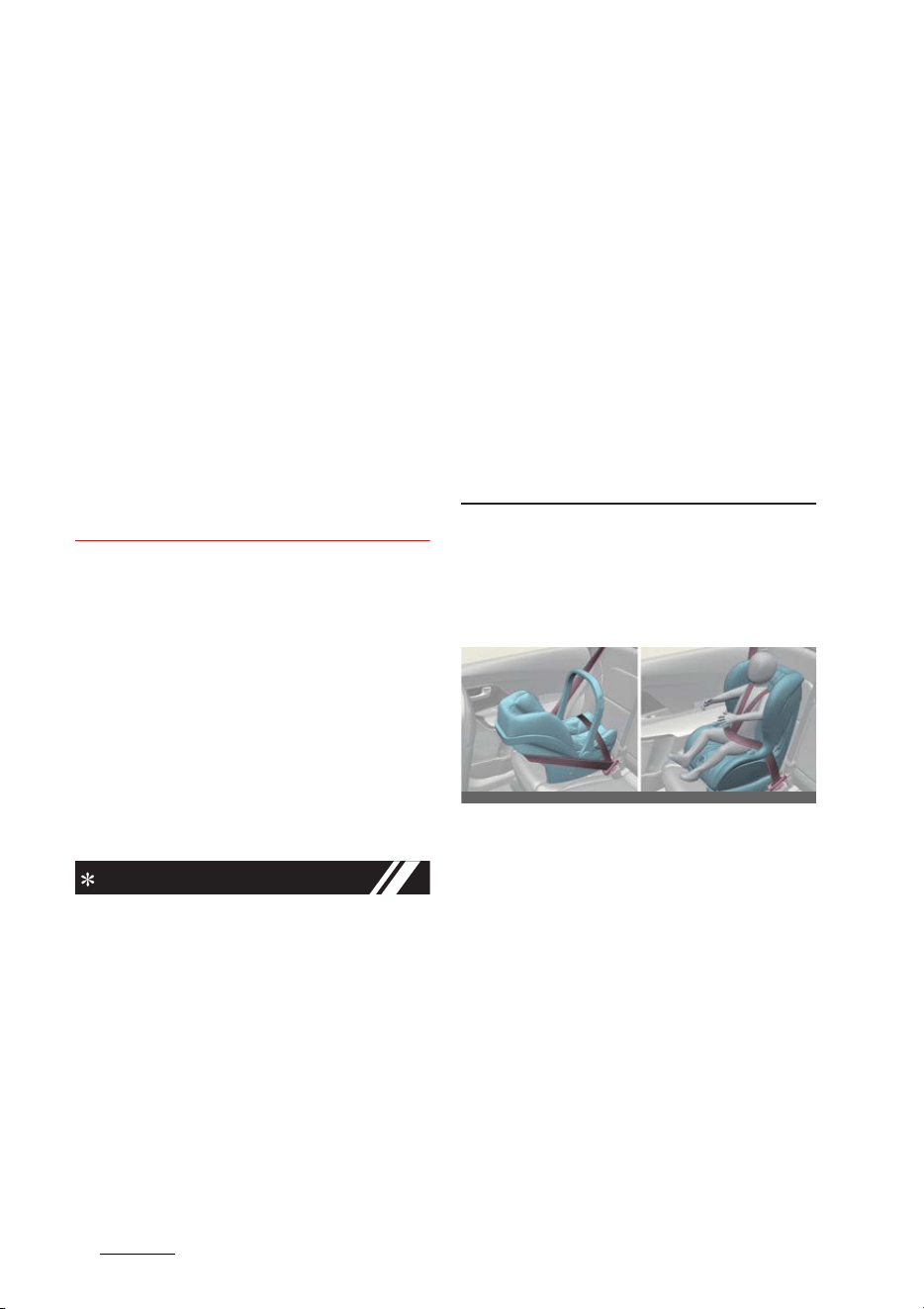
Safety features of your vehicle
224
Child restraint system (CRS)
Restraint System on the front passen
-
ger seat, unless the air bag is deacti
-
vated.
僅 Always follow the Child Restraint Sys
-
tem manufacturer's instructions for
installation and use.
僅 Always properly restrain your child in
the Child Restraint System.
僅 Do not use an infant carrier or a child
safety seat that "hooks" over a seat
-
back, it may not provide adequate
protection in an accident.
僅 After an accident, have the system
checked by a professional workshop.
Kia recommends visiting an autho
-
rized Kia dealer/service partner.
Selecting a Child Restraint Sys
-
tem (CRS)
Operation
僅 Select a Child Restraint System based
on your child's height and weight. The
required label or the instructions for
use typically provide this information.
僅 Select a Child Restraint System that
fits the vehicle seating position where
it will be used.
INFORMATION
僅 Make sure the Child Restraint System
has a label certifying that it meets the
applicable Safety Standards of your
country. A Child Restraint System may
only be installed if it was approved in
accordance with the requirements of
ECE-R44 or ECE-R129 or relevant.
僅 Select a Child Restraint System based
on your child's height and weight. The
required label or the instructions for
use typically provide this information.
僅 Select a Child Restraint System that
fits the vehicle seating position where
it will be used. For the suitability of
Child Restraint Systems on the vehi
-
cle's seating positions, please refer to
"Suitability of each seating position for
belted & ISOFIX Child Restraint Sys
-
tems (CRS) according to UN regula
-
tions (Information for use by vehicle
users and CRS manufacturers)" on
page 4-27.
僅 Read and comply with the warnings
and instructions for installation and
use provided with the Child Restraint
System.
Child restraint system types
Forward/rearward-facing Child
Restraint System
A rearward-facing Child Restraint Sys
-
tem provides restraint with the seating
surface against the back of the child.
The harness system holds the child in
place and, in an accident, keeps the child
positioned in the child restraint system
and reduces stress to the fragile neck
and spinal cord.
All children under the age of one year
must always ride in a rearward-facing
Child Restraint System. There are differ
-
ent types of rearward-facing child
restraint system: infant-only child
restraint systems can only be used fac
-
ing rearward. Convertible and 3-in-1
Child Restraint Systems typically have
OCV031024L_2

23
4
4
Safety features of your vehicle Child restraint system (CRS)
higher height and weight limits for the
rearward-facing position, allowing you to
keep your child rearward-facing for a
longer period of time.
Keep using child restraint systems in the
rearward-facing position as long as the
children are within the height and weight
limits specified by the child restraint sys
-
tem's manufacturer.
A forward-facing Child Restraint System
provides restraint for the child's body
with a harness. Keep children in a for
-
ward-facing child restraint system with a
harness until they reach the maximum
height or weight limit allowed by your
child restraint system's manufacturer.
Once your child outgrows the forward-
facing Child Restraint System, your child
is ready for a booster seat.
Booster seats
A booster seat is a Child Restraint Sys
-
tem designed to improve the fit of the
vehicle's seat belt system. A booster seat
positions the seat belt so that it fits prop
-
erly over the stronger parts of your
child's body. Keep your children in
booster seats until they are big enough
to fit in a seat belt properly.
For a seat belt to fit properly, the lap belt
must lie comfortably across the upper
thighs, not the stomach. The shoulder
belt should lie comfortably across the
shoulder and chest and not across the
neck or face. Children under the age of
13 should always ride in the rear seats;
they must always be restrained properly
to minimize the risk of injury in case of
accident, sudden stop, or sudden
maneuver.
Installing a Child Restraint Sys
-
tem (CRS)
Operation
1. Properly secure the Child Restraint
System to the vehicle.
2. Make sure the Child Restraint System
is firmly secured.
3. Secure the child in the Child Restraint
System.
WARNING
僅Before installing your Child Restraint
System always: Read and follow the
instructions provided by the manufac
-
turer of the Child Restraint System.
Failure to follow all warnings and
instructions could increase the risk of
the serious injury or death if an acci
-
dent occurs.
僅 If the vehicle's headrest prevents
proper installation of a Child Restraint
System, the headrest of the respective
seating position shall be readjusted or
entirely removed.
CAUTION
A Child Restraint System in a closed
vehicle can become very hot. To prevent
burns, check the seating surface and
buckles before placing your child in the
Child Restraint System.
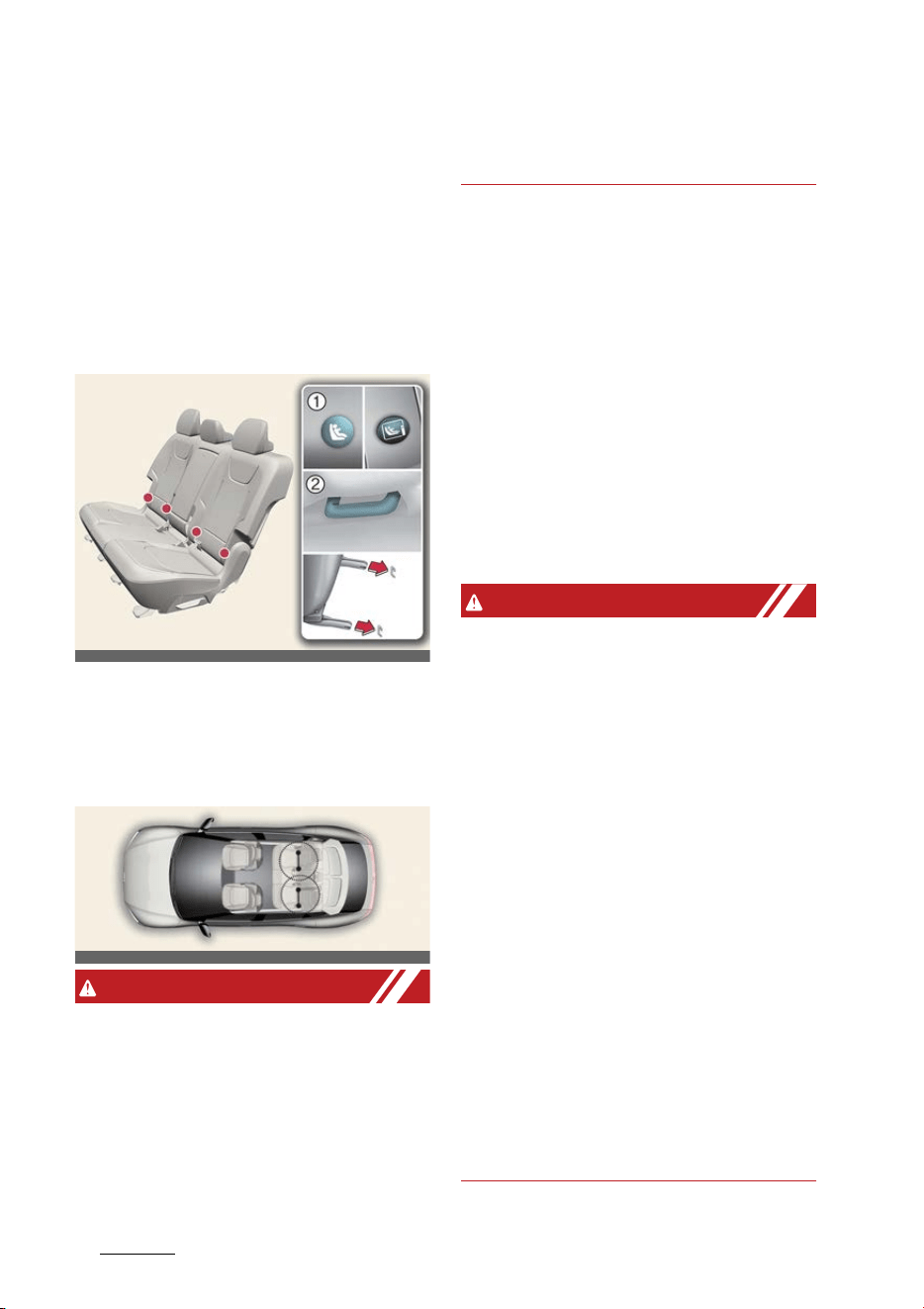
Safety features of your vehicle
244
ISOFIX anchorage and top-tether anchorage (ISOFIX
Anchorage System) for children
ISOFIX anchorage and top-
tether anchorage (ISOFIX
Anchorage System) for chil
-
dren
ISOFIX anchorages are metal bars built
into the vehicle. There are two lower
anchors for each ISOFIX seating position
that will accommodate a Child Restraint
System with lower attachments.
1
ISOFIX anchor position indicator
2
ISOFIX anchor
ISOFIX anchorages have been provided
in the left and right outboard rear seat
-
ing positions.
WARNING
Do not attempt to install a Child
Restraint System using ISOFIX anchor
-
ages in the rear center seating position.
There are no ISOFIX anchorages pro
-
vided for this seat. Using the outboard
seat anchorages, for the CRS installation
on the rear center seating position, can
damage the anchorages.
Securing a Child Restraint System
with the "ISOFIX Anchorage" sys
-
tem
Operation
僅 Move the seat belt buckle away from
the ISOFIX anchorages.
僅 Move any other objects away from
the anchorages.
僅 Place the Child Restraint System on
the vehicle seat, then attach the seat
to the ISOFIX anchorages according
to the instructions provided by the
Child Restraint System manufacturer.
WARNING
Take the following precautions when
using the ISOFIX system:
僅 Read and follow all installation
instructions provided with your Child
Restraint System.
僅 To prevent the child from reaching
and taking hold of unretracted seat
belts, buckle all unused rear seat belts
and retract the seat belt webbing
behind the child. Children can be
strangled if a shoulder belt becomes
wrapped around their neck and the
seat belt tightens.
僅 NEVER attach more than one Child
Restraint System to a single anchor
-
age. This could cause the anchor or
attachment to come loose or break.
僅 Always have the ISOFIX (i- Size) sys
-
tem inspected by your dealer after an
accident. An accident can damage the
ISOFIX system and may not properly
secure the Child Restraint System.
OCV031099L_3
OCV031026L
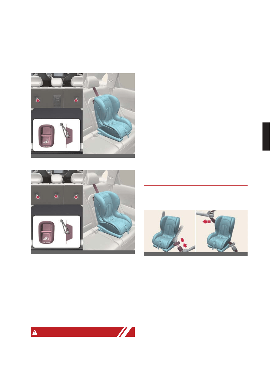
25
4
4
Safety features of your vehicle ISOFIX anchorage and top-tether anchorage (ISOFIX
Anchorage System) for children
Securing a Child Restraint System
with the "Top-tether Anchorage"
system
Type A
Type B
Operation
僅 Route the Child Restraint System seat
strap over the seatback.
僅 Connect the top-tether to the top
-
tether anchorage.
僅 Tighten the top-tether according to
the instructions of your Child
Restraint System's manufacturer.
WARNING
Take the following precautions when
installing the top-tether:
僅 Read and follow all installation
instructions provided with your Child
Restraint System.
僅 NEVER attach more than one Child
Restraint System to a single ISOFIX
top-tether anchorage. This could
cause the anchorage or attachment to
come loose or break.
僅 Do not attach the top-tether to any
-
thing other than the correct top-tether
anchorage. It may not work properly if
attached to something else.
僅 Child restraint anchorages are
designed to withstand only those
loads imposed by correctly fitted child
restraints. Under no circumstances
are they to be used for adult seat
belts, harnesses, or for attaching
other items or equipment to the vehi
-
cle.
Securing a Child Restraint System
with a lap/shoulder belt
Operation
1. Place the Child Restraint System on a
rear seat and route the lap/shoulder
belt around or through the Child
Restraint System.
2. Fasten the lap/shoulder belt latch into
the buckle.
3. Remove as much slack from the belt
as possible by pushing down on the
Child Restraint System while feeding
the shoulder belt back into the retrac
-
tor.
OCV031027L_2
OCV031028L_2
OCV031029L_2

Safety features of your vehicle
264
ISOFIX anchorage and top-tether anchorage (ISOFIX
Anchorage System) for children
4. Push and pull on the Child Restraint
System to confirm that the seat belt is
holding it firmly in place.
5. If your Child Restraint System manu
-
facturer recommends the use of a
top-tether with the lap/shoulder belt,
see Securing a child restraint system
seat with the "top-tether anchorage"
system section in this chapter.
6. To remove the Child Restraint System,
press the release button on the
buckle, and then pull the lap/shoulder
belt out of the Child Restraint System
and allow the seat belt to retract fully.
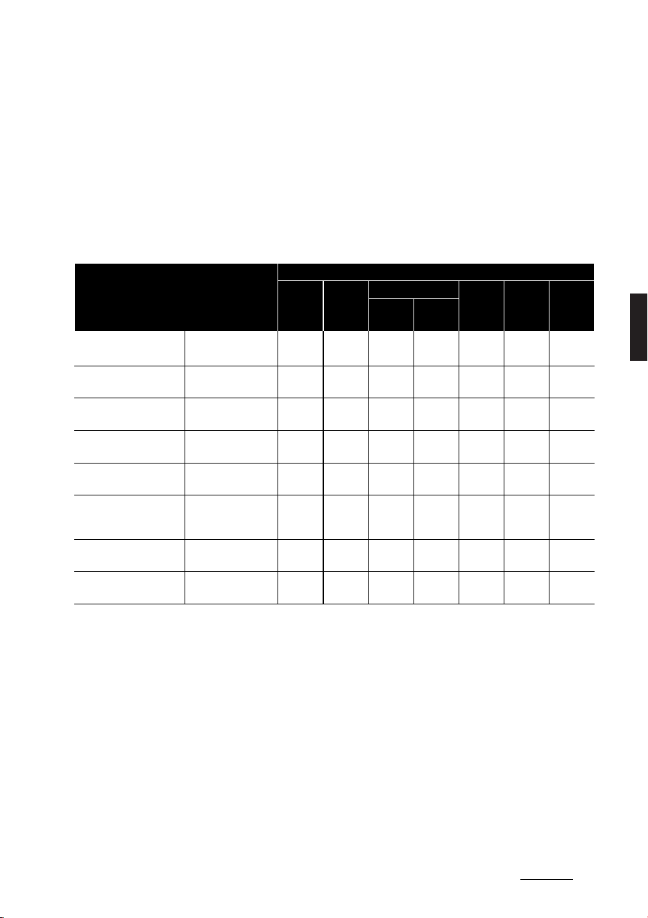
27
4
4
Safety features of your vehicle ISOFIX anchorage and top-tether anchorage (ISOFIX
Anchorage System) for children
Suitability of each seating position for belted & ISOFIX Child Restraint
Systems (CRS) according to UN regulations (Information for use by
vehicle users and CRS manufacturers)
僅 Yes : Suitable for fitment of the designated category of CRS
僅 No : Not suitable for fitment of the designated category of CRS
僅 "-": Not applicable
僅 The table is based on LHD vehicle. Except for the front passenger seat, the table is valid for RHD vehicle. For RHD vehicle front
passenger seat, please use information for the seating position number 3.
F
: Forward facing
R
: Rearward facing
* 1. You should adjust the front passenger seat height to the highest position. (Seat
number 3)
* 2. The seating position (number 5) is not suitable for fitment of child restraint sys
-
tem with support leg.
* 3. For fitment of ISOFIX toddler's rearward large CRS
- Driver Seat: You should move the seat at mid position. (Seat number 1)
- Front Passenger Seat: You should move the seat at mid position. (Seat number 3)
* 4. If the vehicle headrest prevents proper installation of a CRS, the headrest of the
seating position shall be readjusted or entirely removed.
CRS categories
Seating positions
1 2
3
4 5 6
Airbag
ON
Airbag
OFF
Universal belted CRS All mass groups - - No
Yes
*1
(F, R)
Yes
(F, R)
Yes
*2
(F, R)
Yes
(F, R)
i-size CRS
ISOFIX CRF:
F2, F2X, R1, R2
- - No No Yes No Yes
Carry-cot
(ISOFIX lateral facing CRS)
ISOFIX CRF:
L1, L2
- - No No No No No
ISOFIX infant* CRS
(*: ISOFIX baby CRS)
ISOFIX CRF:
R1
- - No No
Yes
(R)
No
Yes
(R)
ISOFIX toddler CRS – small
ISOFIX CRF:
F2, F2X, R2, R2X
- - No No
Yes
(F, R)
No
Yes
(F, R)
ISOFIX toddler CRS –
large*
(*: not booster seats)
ISOFIX CRF:
F3, R3
- - No No
Yes
(F, R
*3
)
No
Yes
(F, R
*3
)
Booster Seat – reduced
Width
ISO CRF:
B2
- - No No
Yes
*4
No
Yes
*4
Booster Seat – full Width
ISO CRF:
B3
- - No No
Yes
*4
No
Yes
*4
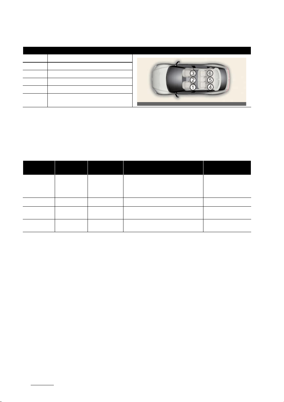
Safety features of your vehicle
284
ISOFIX anchorage and top-tether anchorage (ISOFIX
Anchorage System) for children
* Never place a rearward facing Child Restraint System on the front passenger seat,
unless the air bag is deactivated.
* For semi-universal or vehicle specific CRS (ISOFIX or belted CRS), please see the
vehicle list provided in the manual of CRS
Recommended CRS for Vehicle according to UN regulations
CRS Manufacturer information
Britax R쎨mer: www.britax.com
Peg Perego: www.pegperego.com
Seat Number Position in the vehicle
1 Front left
2 Front center
3 Front right
4 2nd row left
5 2nd row center
6 2nd row right
Child Height /
Mass Group
Name Manufacturer Type of Fixation
ECE-R44
Approval No.
40~83 cm
BABY-SAFE 3 i-
SIZE CRS with
FLEX BASE i-
SENSE
Britax R쎨mer ISOFIX with Support leg (Rearward facing) E1*129R03/04*0060
76~105 cm
TRIFIX
2
i-SIZE
Britax R쎨mer ISOFIX and TOP TETHER E1*129R02/06*001
Group II KidFix2 R Britax R쎨mer
ISOFIX and vehicle belt, using CRS lap belt
guide
ECE-R44-E1-04301304
Group III
Viaggio 2-3 shut
-
tle
Peg Perego ISOFIX and Vehicle belt
ECE R44/04-E24-
0000256
OCV031030L
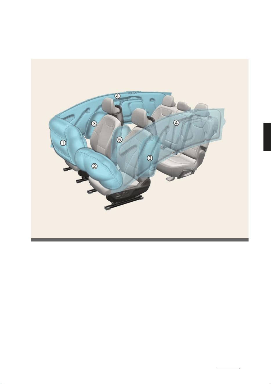
29
4
4
Safety features of your vehicle Air bag – supplemental restraint system
Air bag – supplemental restraint system
Left-hand drive
* The actual features in your vehicle may not necessarily be available due to the
selected options or regions.
1
Passenger's front air bag
2
Driver's front air bag
3
Side air bag
4
Curtain air bag
5
Front center side air bag
OCV031031L
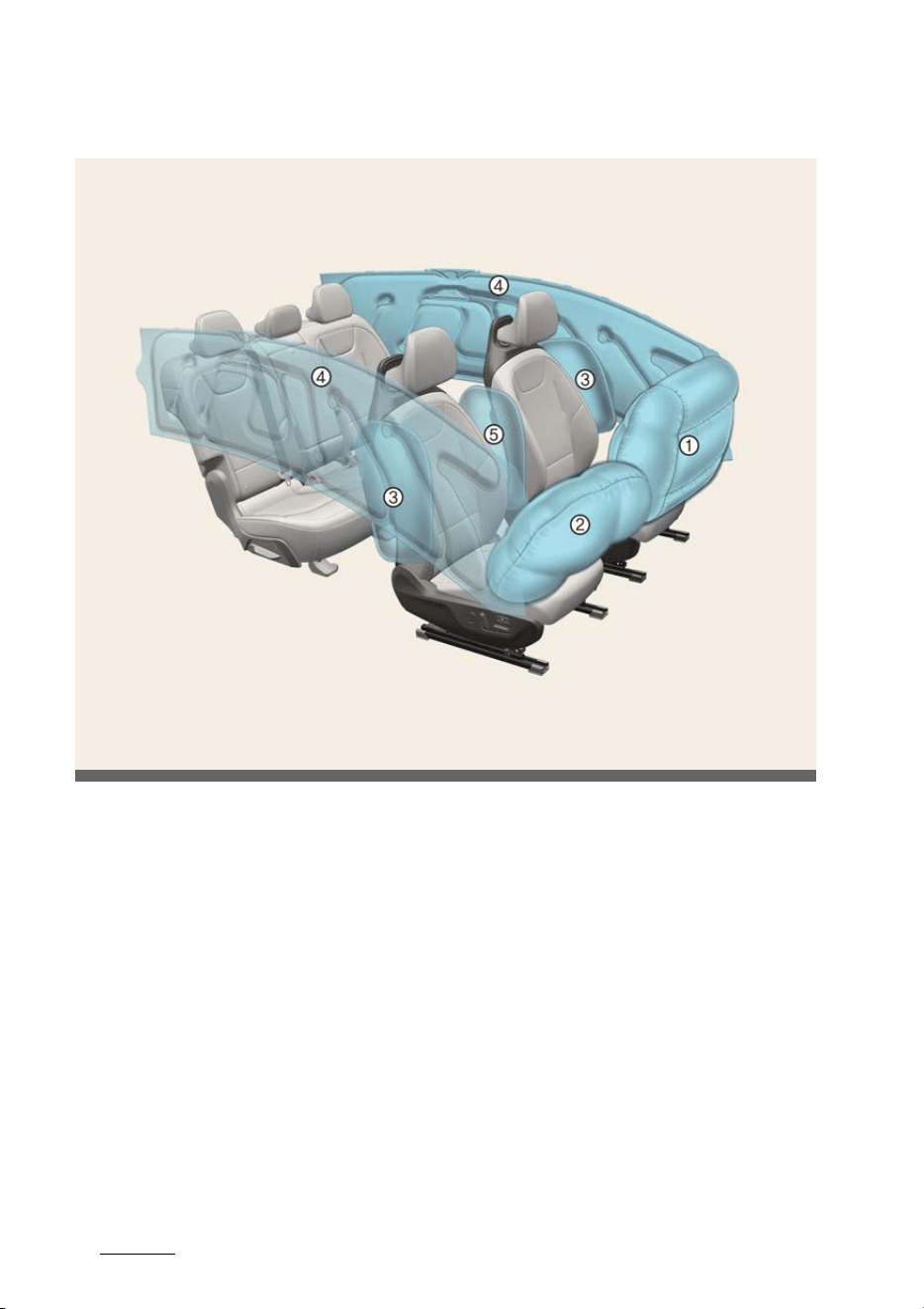
Safety features of your vehicle
304
Air bag – supplemental restraint system
Right-hand drive
* The actual features in your vehicle may not necessarily be available due to the
selected options or regions.
1
Passenger's front air bag
2
Driver's front air bag
3
Side air bag
4
Curtain air bag
5
Front center side air bag
OCV031031R

31
4
4
Safety features of your vehicle Air bag – supplemental restraint system
How does the air bag system
operate?
僅 Air bags are activated (able to inflate
if necessary) only when the EV button
is in the ON position and it can be
activated within about 3 minutes after
the vehicle is in OFF position.
僅 Air bags inflate instantly in the event
of serious frontal or side collision (if a
side air bag or a curtain air bag is
present) in order to help protect the
occupants from serious physical
injury.
僅 Generally, air bags are designed to
inflate based upon the severity of a
collision and its direction, etc. These
two factors determine whether the
sensors produce electronic deploy
-
ment/inflation signal.
僅 Air bags will inflate based upon the
severity of a collision and its direction,
etc. Air bags will not inflate in every
crash or collision situation.
僅 The front air bags will completely
inflate and deflate in an instant. It is
virtually impossible for you to see the
air bags inflate during an accident. It
is much more likely that you will sim
-
ply see the deflated air bags hanging
out of their storage compartments
after the collision.
僅In order to help provide protection in
a severe collision, the air bags must
inflate rapidly. The speed of air bag
inflation is due to the extremely short
time when a collision occurs and the
need to get the air bag between the
occupant and the vehicle structures
before the occupant impacts those
structures. This speed of inflation
reduces the risk of serious or life-
threatening injuries in a severe colli
-
sion and is thus a necessary part of air
bag design.
僅 However, air bag inflation can also
cause injuries, including facial abra
-
sions, bruises, and broken bones,
because the inflation speed also
causes the air bags to expand with a
great deal of force.
僅 There are even circumstances under
which contact with the steering wheel
air bag can cause fatal injuries, espe
-
cially if the occupant is positioned
excessively close to the steering
wheel.
WARNING
僅 Even in vehicles with air bags, you
and your passengers must always
wear the safety belts provided in
order to minimize the risk and severity
of injury in the event of a collision or
in most rollover situations.
僅 SRS and pre-tensioners contain explo
-
sive chemicals. If scraping a vehicle
without removing SRS and pre-ten
-
sioners from a vehicle, it may cause
fire. Before scraping a vehicle, contact
a professional workshop. Kia recom
-
mends visiting an authorized Kia
dealer/service partner.
僅 Keep the SRS parts and wirings away
from water or any liquid. If the SRS
components are inoperative due to
exposure to water or liquids, it may
cause fire or severe injury.
僅 To avoid severe personal injury or
death caused by deploying air bags in
a collision, the driver should sit as far
back from the steering wheel air bag.
The front passenger should always
move their seat as far back as possi
-
ble and sit back in their seat.
僅 Air bag inflates instantly in an event of
a collision, passengers may be injured

Safety features of your vehicle
324
Air bag – supplemental restraint system
by the air bag expansion force if they
are not in a proper position.
僅 Air bag inflation may cause injuries
including facial or bodily abrasions,
injuries from broken glasses or burns.
NOTICE
If equipped with rollover sensor
Also, the air bags inflate instantly in the
event of a rollover (if equipped with a
side air bag or curtain air bag) in order
to help protect the occupants from seri
-
ous physical injury.
Noise and smoke
When the air bags inflate, they make a
loud noise and leave smoke and powder
in the air inside of the vehicle. This is
normal and is a result of the ignition of
the air bag inflator. After the air bag has
inflated, you may feel substantial dis
-
comfort in breathing due to the contact
between your chest and both the seat
belt and the air bag, as well as from
breathing the smoke and powder.
Open your doors and/or windows as
soon as possible after an impact in
order to reduce discomfort and pre
-
vent prolonged exposure to the
smoke and powder.
Though the smoke and powder are non
-
toxic, they may cause skin irritation
(eyes, nose, throat, etc.). If this is the
case, wash and rinse with cold water
immediately and consult the doctor if
the symptom persists.
WARNING
僅 When the air bags deploy, the air bag
related parts in the steering wheel
and/or instrument cluster and/or in
both sides of the roof rails above the
front and rear doors are very hot. To
prevent injury, do not touch the air
bag storage areas internal compo
-
nents immediately after an air bag
has inflated.
僅 Do not install or place any accessories
near air bag deployment areas, such
as the instrument cluster, windows,
pillars, and roof rails.
Air bag warning and indicator
light
Air bag warning light
Operating condition(s)
僅 When the vehicle is running
- The air bag warning light should
illuminate for approximately 3~6
seconds and go off.
Malfunction
僅 The air bag warning light does not
turn on briefly when the vehicle is
running.
僅 The air bag warning light stays on
after illuminating for approximately
3~6 seconds.
僅 The air bag warning light comes on
while the vehicle is moving.
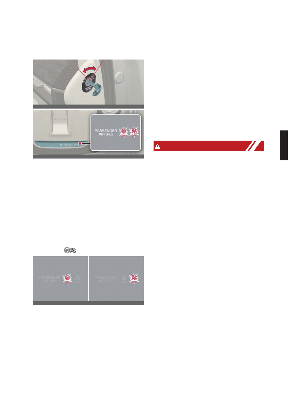
33
4
4
Safety features of your vehicle Air bag – supplemental restraint system
Passenger's front air bag ON/
OFF switch (if equipped)
Operation
1. Insert master key into the passenger's
front air bag ON/OFF switch.
2. Turn the key to activate/deactivate
passenger's front air bag.
僅 When the child restraint is installed
on the front passenger's seat.
僅 When the seat is unoccupied.
Front passenger air bag ON/OFF
indicator
Operating condition(s)
僅 After the vehicle is running
- The Front passenger air bag ON/
OFF indicator illuminates for
approximately 4 seconds.
僅 When the passenger's front air bag
ON/OFF switch is set to the ON/OFF
position
- The Front passenger air bag ON/
OFF indicator is illuminated.
Non-operating condition(s)
僅 When the vehicle is running within
approximately 3 minutes after the
vehicle is turned off
- The front air bag ON/OFF indicator
will not illuminate.
WARNING
僅 The front air bag ON/OFF switch
could turn by using a similar small
rigid device. Always check the status
of the front air bag ON/OFF switch
and Front passenger air bag ON/OFF
indicator.
僅 The driver is responsible for the
proper position of the passenger's
front air bag ON/OFF switch.
僅 Deactivate the passenger's front air
bag only when the EV button is in OFF
position, or the malfunction may
occur in the SRS Control Module.
And there may be a danger that the
driver's and/or front passenger's and/
or side and curtain air bag may fail to
trigger, or not trigger correctly during
a collision.
僅 Never install a rearward facing child
seat on the front passenger's seat
unless the passenger's front air bag
has been deactivated. The infant or
child could be severely injured or
killed by an air bag deployment in
case of an accident.
僅 Even though your vehicle is equipped
with the passenger's front air bag ON/
OFF switch, do not install a child
restraint system in the front passen
-
OCV031032L
OCV031034L
OCV031033L_2
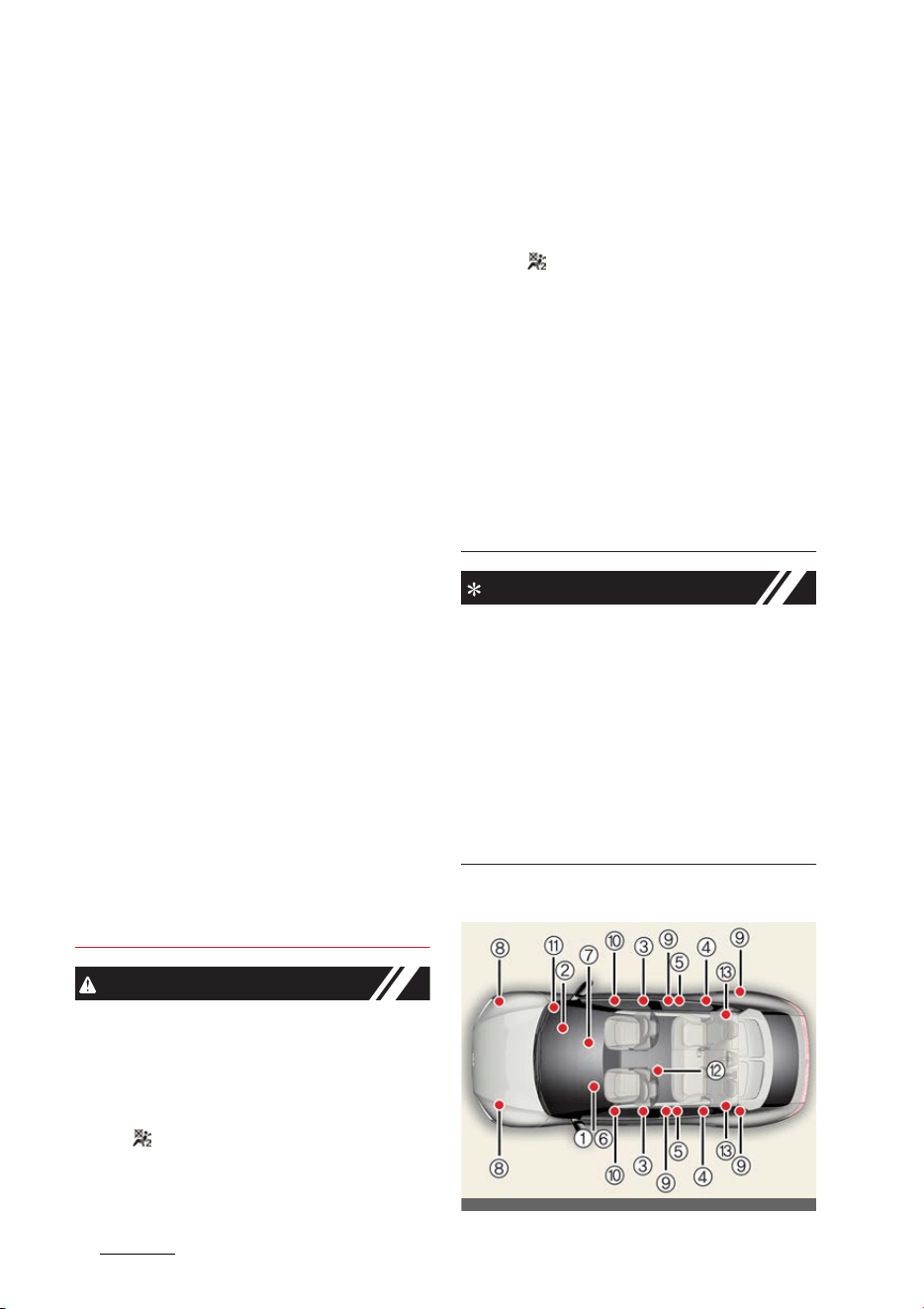
Safety features of your vehicle
344
Air bag – supplemental restraint system
ger's seat. A child restraint system
must never be placed in the front
seat. Children who are too large for
child restraint systems should always
occupy the rear seat and use the
available lap/shoulder belts. In the
event of an accident, children are
afforded the most safety when they
are restrained by a proper restraint
system in the rear seat.
僅 As soon as the child seat is no longer
needed on the front passenger's seat,
reactivate the front passenger's air
bag.
僅 Never place or insert any object into
any small opening near side airbag
labels attached to the vehicle seats.
When the air bag deploys, the object
may affect the deployment and result
in unexpected accident or bodily
harm.
僅 No objects (such as crash pad cover,
cellular phone holder, cup holder, per
-
fume or stickers) should be placed
over or near the air bag modules on
the steering wheel, instrument cluster,
windshield glass, and the front pas
-
senger's panel above the glove box.
Such objects could cause harm if the
vehicle is in a crash severe enough to
cause the air bags to deploy. Do not
place any objects over the air bag or
between the air bag and yourself.
CAUTION
僅 If the passenger's front air bag ON/
OFF switch is not working properly,
the air bag warning light on the instru
-
ment panel will illuminate. And, the
passenger's front air bag OFF indica
-
tor ( ) will not illuminate (The pas
-
senger's front air bag ON indicator
comes on), the SRS Control Module
reactivate the passenger's front air
bag and the passenger's front air bag
will inflate in frontal impact crashes
even if the passenger's front air bag
ON/OFF switch is set to the OFF posi
-
tion ( ). In this case, have the system
inspected by a professional workshop.
Kia recommends visiting an autho
-
rized Kia dealer/service partner.
僅 If the SRS air bag warning light blinks
or does not illuminate when the EV
button is in ON position, or if it illumi
-
nates while the vehicle is being driven,
have the system inspected by a pro
-
fessional workshop. Kia recommends
visiting an authorized Kia dealer/ser
-
vice partner.
NOTICE
僅 When the passenger's front air bag
ON/OFF switch is set to the ON posi
-
tion, the passenger's front air bag is
activated and child or infant seat
should not be installed on the front
passenger's seat.
僅 When the passenger's front air bag
ON/OFF switch is set to the OFF posi
-
tion, the passenger's front air bag is
deactivated.
SRS components and functions
OCV031124L
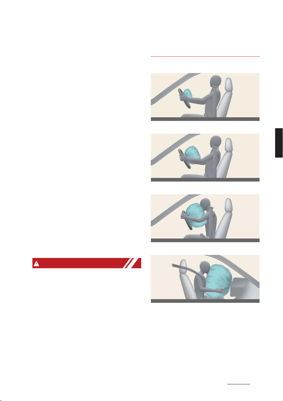
35
4
4
Safety features of your vehicle Air bag – supplemental restraint system
* The actual features in your vehicle may
not necessarily be available due to the
selected options or regions.
1
Driver's front air bag module
2
Passenger's front air bag module
3
Side air bag modules
4
Curtain air bag modules
5
Retractor pre-tensioner assemblies
6
Air bag warning light
7
SRS control module (SRSCM)/rollover
sensor
8
Front impact sensors
9
Side impact sensors
10
Side pressure sensors
11
Passenger's front air bag ON/OFF
switch
12
Driver's center air bag module (if
equipped)
13
Rear retractor pre-tensioner assem
-
blies (if equipped)
Operating condition(s)
僅 EV button is in ON position
- The SRS air bag warning light will
illuminate for approximately 6 sec
-
onds and go out.
WARNING
If any of the following conditions occurs,
this indicates a malfunction of the SRS.
In this case, have the system inspected
by a professional workshop. Kia recom
-
mends visiting an authorized Kia dealer/
service partner.
僅 The light does not turn on briefly
when you turn the vehicle ON.
僅 The light stays on after illuminating
for approximately 6 seconds.
僅 The light comes on while the vehicle is
in motion.
僅 The light blinks when the vehicle is in
ON position.
Driver's front air bag (1)
Driver's front air bag (2)
Driver's front air bag (3)
Passenger's front air bag
The air bag modules are located both in
the center of the steering wheel and in
the front passenger's panel above the
glove box. When the SRSCM detects a
sufficiently severe impact to the front of
the vehicle, it will automatically deploy
the front air bags.
OCV031036L
OCV031037L
OCV031038L
OCV031039L
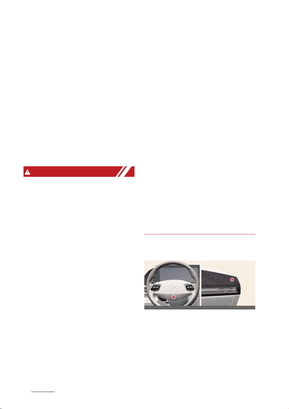
Safety features of your vehicle
364
Air bag – supplemental restraint system
Upon deployment, tear seams molded
directly into the pad covers will separate
under pressure from the expansion of
the air bags. Further opening of the cov
-
ers then allows full inflation of the air
bags.
A fully inflated air bag, in combination
with a properly worn seat belt, slows the
driver's or the passenger's forward
motion, reducing the risk of head and
chest injury.
After complete inflation, the air bag
immediately starts deflating, enabling
the driver to maintain forward visibility
and the ability to steer or operate other
controls.
WARNING
僅 Do not install or place any accessories
(drink holder, CD holder, sticker, etc.)
on the front passenger's panel above
the glove box in a vehicle with a pas
-
senger's air bag. Such objects may
become dangerous projectiles and
cause injury if the passenger's air bag
inflates.
僅 When installing a container of liquid
air freshener inside the vehicle, do not
place it near the instrument cluster
nor on the instrument panel surface.
It may become dangerous projectiles
and cause injury if the passenger's air
bag inflates.
僅 If an air bag deploys, there may be a
loud noise followed by a fine dust
released in the vehicle. These condi
-
tions are normal and are not hazard
-
ous - the air bags are packed in this
fine powder. The dust generated
during air bag deployment may cause
skin or eye irritation as well as aggra
-
vate asthma for some persons.
Always wash all exposed skin areas
thoroughly with cold water and a mild
soap after an accident in which the air
bags were deployed.
僅 The SRS can function only when the
EV button is in the ON position and
within approximately 3 minutes after
the vehicle is in OFF position. If the
SRS air bag warning light does not
illuminate, or continuously remains on
after illuminating for about 6 seconds
when the EV button is in ON position,
or after the vehicle is started, comes
on while driving, the SRS is not work
-
ing properly. In this case, have the
system inspected by a professional
workshop. Kia recommends visiting
an authorized Kia dealer/service part
-
ner.
僅 Before you replace a fuse or discon
-
nect a battery terminal, press EV but
-
ton to OFF position. Never remove or
replace the air bag related fuse(s)
when the EV button is in the ON posi
-
tion. Failure to heed this warning will
cause the SRS air bag warning light to
illuminate.
Driver's and passenger's front air
bags
The indications of the system's presence
are the words
AIR BAG
intagliated on
the air bag pad cover in the steering
wheel, and the passenger's side front
panel pad above the glove box.
OCV031040L_2

37
4
4
Safety features of your vehicle Air bag – supplemental restraint system
WARNING
僅 The driver's hands should be placed
on the steering wheel at the 9:00 and
3:00 positions. The passenger's arms
and hands should be placed on their
laps.
僅 Always use seat belts and child
restraints – every trip, every time,
everyone! Air bags inflate with consid
-
erable force and in the blink of an eye.
Seat belts help keep occupants in
proper position to obtain maximum
benefit from the air bag. Even with air
bags, improperly and unbelted occu
-
pants can be severely injured when
the air bag inflates. Always follow the
precautions about seat belts, air bags
and occupant safety contained in this
manual.
僅 To reduce the chance of serious or
fatal injuries and receive the maxi
-
mum safety benefit from your
restraint system:
- Never place a child in any child or
booster seat in the front seat.
- ABC – Always Buckle Children in
the back seat. It is the safest place
for children of any age to ride.
- Front and side air bags can injure
occupants improperly positioned in
the front seats.
- Move your seat as far back as prac
-
tical from the front air bags, while
still maintaining control of the vehi
-
cle.
- You and your passengers should
never sit or lean unnecessarily
close to the air bags. Improperly
positioned drivers and passengers
can be severely injured by inflating
air bags.
- Never lean against the door or cen
-
ter console – always sit in an
upright position.
- No objects should be placed over or
near the air bag modules on the
steering wheel, instrument panel,
and the front passenger's panel
above the glove box, because any
such object could cause harm if the
vehicle is in a crash severe enough
to cause the air bags to deploy.
- If the SRS air bag warning light
remains illuminated while the vehi
-
cle is being driven, have the system
inspected by a professional work
-
shop. Kia recommends visiting an
authorized Kia dealer/service part
-
ner.
- Air bags can only be used once –
have the system replaced by a pro
-
fessional workshop.
Kia recommends visiting an autho
-
rized Kia dealer/service partner.
- The SRS is designed to deploy the
front air bags only when an impact
is sufficiently severe. Additionally,
the air bags will only deploy once.
Seat belts must be worn at all times.
- Front air bags are not intended to
deploy in side-impact, rear-impact
or rollover crashes. In addition,
front air bags will not deploy in
frontal crashes below the deploy
-
ment threshold.
- A child restraint system must never
be placed in the front seat. The
infant or child could be severely
injured or killed by an air bag
deployment in case of an accident.
- Children age 13 and under must
always be properly restrained in the
rear seat. Never allow children to
ride in the front passenger seat. If a
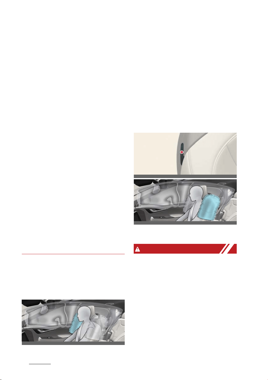
Safety features of your vehicle
384
Air bag – supplemental restraint system
child over age 13 must be seated in
the front seat, he or she must be
properly belted and the seat should
be moved as far back as possible.
- For maximum safety protection in
all types of crashes, all occupants
including the driver should always
wear their seat belts whether or not
an air bag is also provided at their
seating position to minimize the
risk of severe injury or death in the
event of a crash. Do not sit or lean
unnecessarily close to the air bag
while the vehicle is in motion.
- Sitting improperly or out of position
can result in serious or fatal injury
in a crash. All occupants should sit
upright with the seat back in an
upright position, center on the seat
cushion with their seat belt on, legs
comfortably extended and their
feet on the floor until the vehicle is
parked.
- The SRS air bag system must
deploy very rapidly to provide pro
-
tection in a crash. If an occupant is
out of position because of not
wearing a seat belt, the air bag may
forcefully contact the occupant
causing serious or fatal injuries.
Side air bag and front center air
bag
Your vehicle is equipped with a side air
bag in each front and front center air
bag in each front seat.
* The actual air bags in the vehicle may
differ from the illustration.
The purpose of the air bag is to provide
the vehicle's driver and/or front passen
-
ger with protection in addition to that
offered by the seat belt alone.
The side air bags and front center air
bag are designed to deploy only during
certain side-impact collisions, depending
on the crash severity. The side air bags
and driver's center air bag are not
designed to deploy in all side impact sit
-
uations.
* The actual air bags in the vehicle may
differ from the illustration.
WARNING
僅 Do not allow the passengers to lean
their heads or bodies onto doors, put
their arms on the doors, stretch their
arms out of the window, or place
objects between the doors and pas
-
sengers when they are seated on
seats equipped with side and/or cur
-
tain air bags.
僅 The side air bag and front center air
bag are supplemental to the driver's
and the passenger's seat belt systems
and is not a substitute for them.
Therefore your seat belts must be
OCV031041L
OCV031042L
OCV031043L
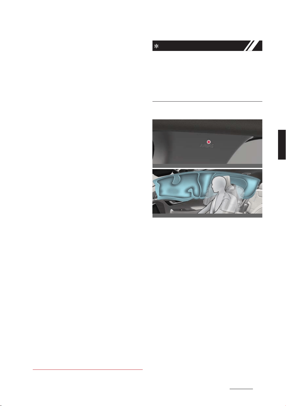
39
4
4
Safety features of your vehicle Air bag – supplemental restraint system
worn at all times while the vehicle is in
motion. The air bags deploy only in
certain side impact or rollover condi
-
tions (Only vehicle equipped with roll
-
over sensor) severe enough to cause
significant injury to the vehicle occu
-
pants.
僅 For best protection from the side air
bag system and to avoid being injured
by the deploying side air bag, both
front seat occupants should sit in an
upright position with the seat belt
properly fastened.
僅 Do not use any accessory seat covers.
僅 Use of seat covers could reduce or
prevent the effectiveness of the sys
-
tem.
僅 To prevent unexpected deployment
of the side air bag and driver's center
air bag that may result in personal
injury, avoid impact to the side impact
sensor when the EV button is in ON
position and within approximately 3
minutes after the vehicle is in OFF
position.
僅 If the seat or seat cover is damaged,
have the system serviced by a profes
-
sional workshop.
Kia recommends visiting an autho
-
rized Kia dealer/service partner.
僅 Do not place any objects over the air
bag or between the air bag and your
-
self. Also, do not attach any objects
around the area the air bag inflates
such as the door, side door glass,
front and rear pillar.
僅 Do not place any objects between the
door and the seat. They may become
dangerous projectiles if the side air
bag inflates.
僅 Do not install any accessories on the
side or near the side air bags.
NOTICE
僅 If equipped with rollover sensor
Also, the air bags inflate instantly in
the event of a rollover (if equipped
with a side air bag or curtain air bag)
in order to help protect the occupants
from serious physical injury.
Curtain air bag
* The actual air bags in the vehicle may
differ from the illustration.
Curtain air bags are located along both
sides of the roof rails above the front
and rear doors.
They are designed to help protect the
heads of the front seat occupants and
the rear outboard seat occupants during
certain side impact collisions.
The curtain air bags are designed to
deploy during certain side impact colli
-
sions, depending on the crash severity.
The curtain air bags are not designed to
deploy in all side impact situations, or
during collisions from the front or rear of
the vehicle or in most rollover situations.
OCV031044L
OCV031045L

Safety features of your vehicle
404
Air bag – supplemental restraint system
WARNING
僅 Failure to follow the instructions men
-
tioned can result in injury or death to
the vehicle occupants in an accident.
- Do not hang heavy items on the
coat hooks for safety reasons.
- In order for side and curtain air
bags to provide the best protection,
both front seat occupants and both
outboard rear occupants should sit
in an upright position with the seat
belts properly fastened.
Importantly, children should sit in a
proper child restraint system in the
rear seat.
- When children are seated in the
rear outboard seats, they must be
seated in the proper child restraint
system.
Make sure to put the child restraint
system as far away from the door
side as possible, and secure the
child restraint system in a locked
position.
-Do not allow the passengers to lean
their heads or bodies onto doors,
put their arms on the doors, stretch
their arms out of the window, or
place objects between the doors
and passengers when they are
seated on seats equipped with side
and/or curtain air bags.
- Never try to open or repair any
components of the curtain air bag
system. If necessary, have the sys
-
tem serviced by a professional
workshop. Kia recommends visit
-
ing an authorized Kia dealer/ser
-
vice partner.
僅 Do not place any objects over the air
bag. Also, do not attach any objects
around the area the air bag inflates
such as the door, side door glass,
front and rear pillar, roof side rail.
僅 Do not hang hard or breakable
objects on the clothes hanger.
NOTICE
If equipped with rollover sensor
Also, the air bags inflate instantly in the
event of a rollover (if equipped with a
side air bag or curtain air bag) in order
to help protect the occupants from seri
-
ous physical injury.
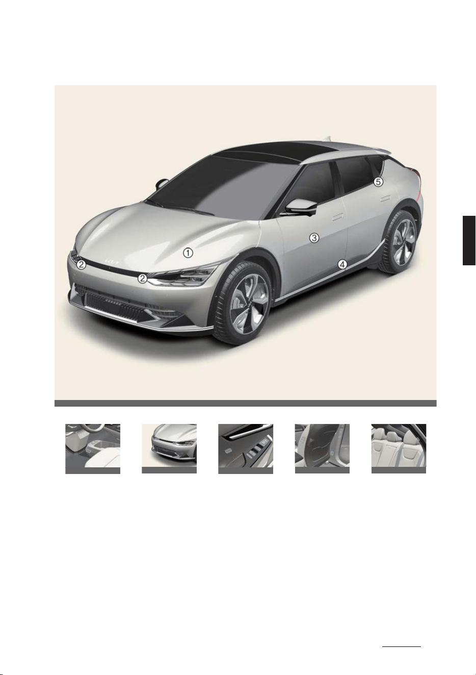
41
4
4
Safety features of your vehicle Air bag – supplemental restraint system
Air bag collision sensors
* The actual features in your vehicle may not necessarily be available due to the
selected options or regions.
1
Supplemental Restraint System (SRS) control module/rollover sensor
2
Front impact sensor
3
Side pressure sensors (front door)
4
Side impact sensor (B-pillar)
5
Side impact sensor (C-pillar)
1 2 3 4 5
OCV031046L
OCV031047L
OCV031048L
OCV031049L
OCV031050L
OCV031051L
Safety features of your vehicle
424
Air bag – supplemental restraint system
WARNING
僅 Do not hit or allow any objects to
impact the locations where air bag or
sensors are installed.
This may cause unexpected air bag
deployment, which could result in
serious personal injury or death.
僅If the installation location or angle of
the sensors is altered in any way, the
air bags may deploy when they
should not or they may not deploy
when they should, causing severe
injury or death.
Therefore, do not try to perform main
-
tenance on or around the air bag sen
-
sors. Have the system serviced by a
professional workshop. Kia recom
-
mends visiting an authorized Kia
dealer/service partner.
僅 Problems may arise if the sensor
installation angles are changed due to
the deformation of the front bumper,
body or B pillar where side collision
sensors are installed. In this case,
have the system serviced by a profes
-
sional workshop. Kia recommends to
visit an authorized Kia dealer/service
partner.
僅 Your vehicle has been designed to
absorb impact and deploy the air
bag(s) in certain collisions
Use only Kia Genuine Parts or those
of an equivalent standard to install
bumper guards or replace a bumper.
If not, it may adversely affect your
vehicle’s collision and air bag deploy
-
ment performance.
僅 If equipped with rollover sensor
If your vehicle is equipped with side
and curtain air bag, press EV button
to OFF position and wait for 3 minutes
when the vehicle is being towed.
The side and curtain air bag may
deploy when the EV button is in ON or
OFF position within 3 minutes, and
the rollover sensor detects the situa
-
tion as a rollover.
Air bag inflation conditions
* The actual air bags in the vehicle may differ from the illustra
-
tion.
INFORMATION
僅 Side and curtain air bags
The side and curtain air bags are
designed to inflate when a rollover is
detected by a rollover sensor.
Although the front air bags (driver's
and front passenger's air bags) are
designed to inflate only in frontal colli
-
sions, they also may inflate in other
types of collisions if the front impact
sensors detect a sufficient impact.
Side air bags (side and/or curtain air
bags) are designed to inflate only in
side impact collisions, but they may
inflate in other collisions if the side
impact sensors detect a sufficient
impact.
For instance, side airbag and curtain
air bags may inflate if rollover sensors
Air bag inflation conditions
Front air bags are designed to
inflate in a frontal collision
depending on the intensity,
speed or angles of impact of
the front collision.
Side and/or curtain air bags
are designed to inflate when
an impact is detected by side
collision sensors depending
on the strength, speed or
angles of impact resulting
from a side impact collision.
OCV031052L
OCV031045L
OCV031056L
43
4
4
Safety features of your vehicle Air bag – supplemental restraint system
indicate the possibility of a rollover
occurring (even if none actually
occurs) or in other situations, includ
-
ing when the vehicle is tilted while
being towed. Even if side and/or cur
-
tain air bags do not provide impact
protection in a rollover, they will
deploy to prevent ejection of occu
-
pants, especially those who are
restrained with seat belts.
If the vehicle chassis is impacted by
bumps or objects on unimproved
roads or sidewalks, air bags may
deploy. Drive carefully on unimproved
roads or on surfaces not designed for
vehicle traffic to prevent unintended
air bag deployment.
NOTICE
If equipped with rollover sensor
Also, the side and curtain air bags are
designed to inflate when a rollover is
detected by a rollover sensor.
Air bag non-inflation conditions
WARNING
僅 The SRS is designed to deploy the
front air bags only when an impact is
sufficiently severe and when the
impact angle is less than 30° from the
forward longitudinal axis of the vehi
-
cle.
僅 Front air bags are not intended to
deploy in side-impact, rear-impact or
rollover crashes. In addition, front air
bags will not deploy in frontal crashes
below the deployment threshold.
僅 The air bags deploy only in certain
side impact or rollover conditions
(Only vehicle equipped with rollover
sensor) severe enough to cause sig
-
nificant injury to the vehicle occu
-
pants.
Air bag non-inflation conditions
In certain low-speed collisions
the air bags may not deploy.
Air bags are not designed to
inflate in rear collisions.
Heavy braking lowers the
front portion of the vehicle
causing it to "ride" under a
vehicle with a higher ground
clearance.
Air bags may not inflate in this
"under-ride" situation because
deceleration forces that are
detected by sensors may be
significantly reduced by such
"under-ride" collisions.
OCV031052L
OCV031053L
OCV031054L
In an angled collision, the force
of impact may send the occu
-
pants in a direction where the
air bags would not be able to
provide any additional benefit;
thus, the sensors may not
deploy any air bags.
Front air bags may not inflate
in side impact collisions.
Air bags may not inflate in roll
-
over accidents because the
vehicle cannot detect the roll
-
over.
Air bags may not inflate if the
vehicle collides with objects
such as utility poles or trees,
meaning the point of impact is
concentrated in one area and
the full force of the impact is
not delivered to the sensors.
Air bag non-inflation conditions
OCV031055L
OCV031056L
OCV031057L
OCV031058L

Safety features of your vehicle
444
Air bag – supplemental restraint system
僅 Deactivate the passenger's front air
bag only when the vehicle is in OFF
position, or the malfunction may
occur in the SRS Control Module. And
there may be a danger that the
driver's and/or front passenger's and/
or side and curtain air bag may fail to
trigger, or not trigger correctly during
a collision.
僅 If an air bag deploys, there may be a
loud noise followed by a fine dust
released in the vehicle. These condi
-
tions are not hazardous.
僅 The air bags are packed in this fine
power. The dust generated during air
bag deployment It may cause skin or
eye irritation as well as aggravate
asthma for some persons. Always
wash all exposed skin areas thor
-
oughly with cold water and a mild
soap after an accident in which the air
bags were deployed.
僅 For cleaning the air bag pad covers,
use only a soft, dry cloth or one which
has been moistened with plain water.
僅 Solvents or cleaners could adversely
affect the air bag covers and proper
deployment of the system.
僅 Keep the SRS parts and wirings away
from water or any liquid. If the SRS
components are inoperative due to
exposure to water or liquids, it may
cause fire or severe injury.
僅 If any of the following conditions
occurs, this indicates a malfunction of
the SRS. In this case, have the system
inspected by a professional workshop.
Kia recommends visiting an autho
-
rized Kia dealer/service partner.
- The light does not turn on briefly
when you turn the vehicle ON.
- The light stays on after illuminating
for approximately 6 seconds.
- The light comes on while the vehi
-
cle is in motion.
- The light blinks when the EV button
is in ON position.
僅 Before you replace a fuse or discon
-
nect a battery terminal, turn the EV
button to OFF position. Never remove
or replace the air bag related fuse(s)
when the EV button is in the ON posi
-
tion. Failure to heed this warning will
cause the SRS air bag warning light to
illuminate.
僅 Do not tamper with or disconnect wir
-
ing or other components of the SRS
system, including the addition of any
kind of badges to the pad covers or
modifications to the body structure.
Doing so could adversely affect SRS
performance and lead to possible
injury. If necessary, have the system
serviced by a professional workshop.
Kia recommends visiting an autho
-
rized Kia dealer/service partner.
僅 If your vehicle was flooded and has
soaked carpeting or water on flooring,
you shouldn't try to start the vehicle;
In this situation, have your vehicle
inspected by a professional workshop.
Kia recommends to contact an autho
-
rized Kia dealer/service partner.
僅 Air bags can only be used once. If the
air bags inflate, have the system
replaced by a professional workshop.
Kia recommends visiting an autho
-
rized Kia dealer/service partner.
僅 If components of the air bag system
must be discarded, or if the vehicle
must be scrapped, certain safety pre
-
cautions must be observed, such as
removing SRS and pre-tensioners
from a vehicle due to the risk of fire.
Failure to follow these precautions
and procedures could increase the

45
4
4
Safety features of your vehicle Air bag – supplemental restraint system
risk of personal injury. An authorized
Kia dealer knows these precautions
and can give you the necessary infor
-
mation.
NOTICE
僅 With rollover sensor
The side and curtain air bags are
designed to inflate when a rollover is
detected by a rollover sensor. The air
bags may inflate in a rollover, when it
is detected by the rollover sensor.
僅 Without rollover sensor
The side and/or curtain air bags may
inflate when the vehicle is rolled over
by a side impact collision, if the vehi
-
cle is equipped with side air bags and
curtain air bags.
SRS care
The SRS is virtually maintenance-free,
and there are no parts you can safely
service by yourself.
If the SRS air bag warning light does not
illuminate, or continuously remains on,
have the system inspected by a profes
-
sional workshop. Kia recommends visit
-
ing an authorized Kia dealer/service
partner.
WARNING
僅 Modification to SRS components or
wiring, including the addition of any
kind of badges to the pad covers or
modifications to the body structure,
can adversely affect SRS performance
and lead to possible injury.
僅 If components of the air bag system
must be discarded, or if the vehicle
must be scrapped, certain safety pre
-
cautions must be observed. An autho
-
rized Kia dealer knows these
precautions and can give you the nec
-
essary information. Failure to follow
these precautions and procedures
could increase the risk of personal
injury.
Additional safety precautions
僅
Never let passengers ride in the
cargo area or on top of a folded-
down back seat.
All occupants
should sit upright, fully back in their
seats with their seat belts on and their
feet on the floor.
僅
Passengers should not move out of
or change their seat while the vehi
-
cle is moving.
A passenger who is not
wearing a seat belt during a crash or
emergency stop can be thrown
against the inside of the vehicle,
against other occupants, or out of the
vehicle.
僅
Each seat belt is designed to
restrain one occupant.
If more than
one person uses the same seat belt,
they could be seriously injured or
killed in a collision.
僅
Do not use any accessories on seat
belts.
Devices claiming to improve
occupant comfort or reposition the
seat belt can reduce the protection
provided by the seat belt and increase
the chance of serious injury in a crash.
僅
Passengers should not place hard
or sharp objects between them
-
selves and the air bags.
Carrying
hard or sharp objects on your lap or in
your mouth can result in injuries if an
air bag inflates.
僅
Keep occupants away from the air
bag covers.
All occupants should sit
upright, fully back in their seats with
their seat belts on and their feet on
the floor. If occupants are too close to
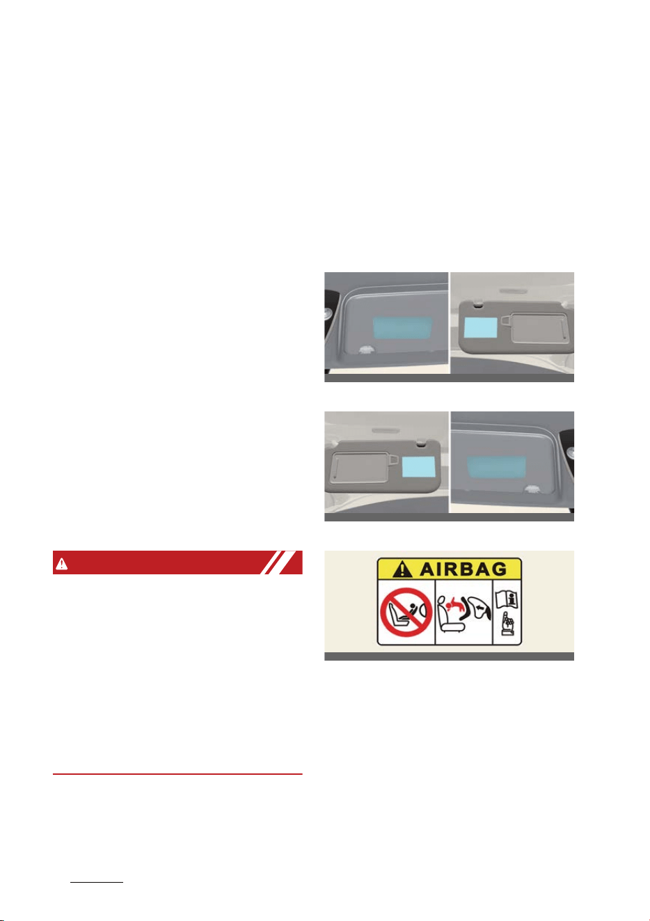
Safety features of your vehicle
464
Air bag – supplemental restraint system
the air bag covers, they could be
injured if the air bags inflate.
僅
Do not attach or place objects on or
near the air bag covers.
Any object
attached to or placed on the front or
side air bag covers could interfere
with the proper operation of the air
bags.
僅
Do not modify the front seats.
Modi
-
fication of the front seats could inter
-
fere with the operation of the
supplemental restraint system sens
-
ing components or side air bags.
僅
Do not place items under the front
seats.
Placing items under the front
seats could interfere with the opera
-
tion of the supplemental restraint sys
-
tem sensing components and wiring
harnesses.
僅
Never hold an infant or child on
your lap.
The infant or child could be
seriously injured or killed in the event
of a crash. All infants and children
should be properly restrained in
appropriate child safety seats or seat
belts in the rear seat.
WARNING
僅 Sitting improperly or out of position
can cause occupants to be shifted too
close to a deploying air bag, strike the
interior structure or be thrown from
the vehicle resulting in serious injury
or death.
僅 Always sit upright with the seatback in
an upright position, centered on the
seat cushion with your seat belt on,
legs comfortably extended and your
feet on the floor.
Adding equipment to or modify
-
ing your air bag-equipped vehicle
Modifying your vehicle by changing your
vehicle's frame, bumper system, front
end or side sheet metal, or ride height
may affect the operation of your vehi
-
cle's air bag system.
Air bag warning labels
Left-hand drive
Right-hand drive
Air bag warning label
Air bag warning labels are attached to
alert the passengers to potential risks of
the air bag system.
Note that these government warnings
focus on the risks to children. We also
want you to be aware of the risks that
adults are exposed to, which have been
described in previous pages.
OCV031059L_2
OCV031059R_2
OCV031062L

47
4
4
Safety features of your vehicle Air bag – supplemental restraint system
WARNING
僅 Never place a rear facing child
restraint in the front passenger seat,
unless the passenger-side air bag is
deactivated. An inflating passenger-
side air bag could impact the rear-fac
-
ing child restraint and kill the child.
僅 Extreme Hazard! Do not use a rear
-
ward facing child restraint on a seat
protected by an air bag in front of it!
僅 Never put a child restraint in the front
passenger's seat. If the front passen
-
ger air bag inflates, it can cause seri
-
ous or fatal injuries.
僅 NEVER use a rearward facing child
restraint on a seat protected by an
ACTIVE AIR BAG in front of it. DEATH
or SERIOUS INJURY to the CHILD can
occur.
僅 When children are seated in the rear
outboard seats of a vehicle equipped
with side and/or curtain air bags, be
sure to install the child restraint sys
-
tem as far away from the door side as
possible, and securely lock the child
restraint system in position.
Inflation of side and/or curtain air
bags could cause serious injury or
death to an infant or child.
NOTICE
If equipped with rollover sensor
僅 The air bags inflate instantly in the
even of a rollover (if equipped with a
side air bag or curtain air bag) in order
to help protect the occupants from
serious physical injury.
僅 The side and/or the curtain air bag
may deploy when the rollover sensor
detects the situation as a rollover.


5Features of your vehicle
Features of your vehicle
Keys.................................................................................................5-6
僅 Record your key number.............................................................................. 5-6
僅 Locking/unlocking/remote starting/remote parking with the smart
key........................................................................................................................... 5-6
僅 Replacing the key battery............................................................................ 5-7
Immobilizer system .......................................................................5-8
僅 Vehicles with smart key system ................................................................5-8
Theft-alarm system .......................................................................5-9
僅 Armed stage....................................................................................................... 5-9
僅 Ultrasonic Intrusion Protection (UIP)....................................................... 5-9
僅 Theft-alarm stage ............................................................................................ 5-9
僅 Disarmed stage...............................................................................................5-10
Door locks......................................................................................5-11
僅 Door locks outside the vehicle ..................................................................5-11
僅 Door locks inside the vehicle .................................................................... 5-13
僅 Automatic door lock and unlock features........................................... 5-15
僅 Deadlocks.......................................................................................................... 5-15
僅 Manual door lock switch............................................................................. 5-15
僅 Rear door locks ............................................................................................... 5-16
僅 Rear Occupant Alert (ROA) ....................................................................... 5-17
Driver position memory system................................................. 5-19
僅 Setting memory position............................................................................. 5-19
僅 Recalling memory position ........................................................................ 5-19
僅 Resetting the driver position memory system................................. 5-20
僅 Easy access function ................................................................................... 5-20
Tailgate ......................................................................................... 5-21
僅 Opening/closing the manual tailgate.....................................................5-21
僅 Opening/closing the power tailgate .......................................................5-21
Windows .......................................................................................5-28
僅 Controlling windows switch......................................................................5-30

5 Features of your vehicle
僅 Resetting the power windows................................................................. 5-30
僅 Power windows automatic reversal...................................................... 5-30
僅 Power windows lock button..................................................................... 5-30
僅 Remote window closing/opening .......................................................... 5-30
Hood ..............................................................................................5-32
僅 Opening/closing the hood ......................................................................... 5-32
Front trunk....................................................................................5-33
僅 Opening the front trunk..............................................................................5-33
僅 Closing the front trunk ................................................................................5-33
Charging door ............................................................................. 5-34
僅 Opening/closing the charging door ......................................................5-34
Wide sunroof............................................................................... 5-36
僅 Power sunshade.............................................................................................5-36
僅 Tilt open/close.................................................................................................5-37
僅 Slide open/close .............................................................................................5-37
僅 Automatic reversal ........................................................................................5-37
僅 Resetting the sunroof...................................................................................5-38
僅 Sunroof open warning.................................................................................5-39
Steering wheel ............................................................................ 5-39
僅 Adjusting the steering wheel angle and height................................5-39
僅 Heated steering wheel.................................................................................5-39
僅 Horn....................................................................................................................5-40
Mirrors.......................................................................................... 5-42
僅 Interior rearview mirror ...............................................................................5-42
僅 Outside rear view mirror.............................................................................5-42
Instrument cluster....................................................................... 5-45
LCD display.................................................................................. 5-47
僅 Changing LCD display modes..................................................................5-47
僅 LCD display modes .......................................................................................5-47
僅 LCD display messages..................................................................................5-51

5Features of your vehicle
Vehicle settings (infotainment system)....................................5-53
Warning and indicator lights .....................................................5-54
Augmented Reality HUD ........................................................... 5-58
僅 Head-up display settings........................................................................... 5-58
僅 Head-up display information................................................................... 5-58
僅 Precautions while using the head-up display ...................................5-59
Lighting........................................................................................ 5-60
僅 Battery saver function................................................................................. 5-60
僅 Headlamp escort function.........................................................................5-60
僅 Daytime Running Light (DRL)................................................................... 5-61
僅 Traffic change (For Europe) ...................................................................... 5-61
僅 Lighting controls............................................................................................. 5-61
僅 High Beam Assist (HBA)..............................................................................5-63
僅 Intelligent front-lighting system (IFS)....................................................5-65
僅 Headlamp leveling adjustment................................................................5-67
Wipers and washers ................................................................... 5-68
僅 Wipers ................................................................................................................ 5-68
僅 Washers............................................................................................................. 5-68
Welcome system..........................................................................5-70
僅 Body silhouette lamp................................................................................... 5-70
僅 Headlamp escort function......................................................................... 5-70
僅 Interior lighting............................................................................................... 5-70
Interior lights................................................................................ 5-71
僅 Automatic turn-off function ...................................................................... 5-71
僅 Map lamp........................................................................................................... 5-71
僅 Room lamp........................................................................................................ 5-71
僅 Luggage space lamp .................................................................................... 5-71
僅 Vanity mirror lamp ........................................................................................ 5-71
僅 Glove box lamp...............................................................................................5-72
Climate control system ...............................................................5-72
Automatic climate control system.............................................5-75

5 Features of your vehicle
僅 Using the infotainment/climate switchable controller ..................5-76
僅 Operating the climate control system..................................................5-77
僅 Controlling heating and air conditioning automatically .............. 5-80
僅 Controlling the temperature .................................................................... 5-80
僅 Adjusting the driver and passenger side temperature to the same
value.................................................................................................................... 5-80
僅 Changing temperature scale ................................................................... 5-80
僅 Controlling fan speed................................................................................... 5-81
Windshield defrosting and defogging..................................... 5-82
僅 Defrosting/defogging the windshield ...................................................5-82
僅 Auto defogging for automatic climate control ................................5-82
僅 Rear window/outside mirror defroster.................................................5-83
僅 Heat button.......................................................................................................5-83
僅 Auto. controls that use climate control settings.............................. 5-84
僅 Smart ventilation........................................................................................... 5-84
Storage compartment ................................................................ 5-85
僅 Center console storage/glove box .........................................................5-85
僅 Luggage tray....................................................................................................5-86
僅 Luggage net holder.......................................................................................5-86
僅 Cargo security screen ..................................................................................5-86
Interior features .......................................................................... 5-88
僅 Ambient lights ................................................................................................ 5-88
僅 Cup holders ..................................................................................................... 5-88
僅 Seat warmer/ventilation............................................................................. 5-88
僅 Sun visor ........................................................................................................... 5-90
僅 USB charger .................................................................................................... 5-90
僅 Power outlet ..................................................................................................... 5-91
僅 Wireless smartphone charging system................................................5-92
僅 Coat hook ..........................................................................................................5-93
僅 Floor mat anchors..........................................................................................5-94
Infotainment system................................................................... 5-94
僅 Using the infotainment/climate switchable controller ..................5-94

5Features of your vehicle
僅 Audio system....................................................................................................5-95
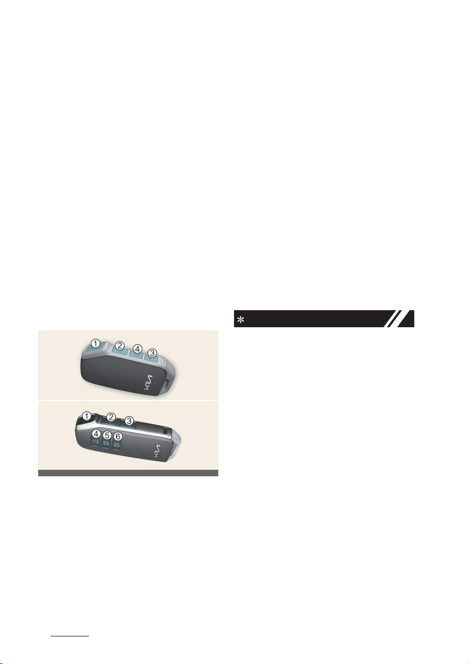
Features of your vehicle
65
Keys
Features of your vehicle
* The information provided may differ
according to which functions are
applicable to your vehicle.
Keys
Record your key number
The key code number is stamped on the
key code tag attached to the key set.
If you lose your keys, Kia recommends
contacting an authorized Kia dealer/ser
-
vice partner. Remove the key code tag
and store it in a safe place. Also, record
the key code number and keep it in a
safe place (not in the vehicle).
Locking/unlocking/remote start
-
ing/remote parking with the
smart key
Smart key
1
Lock
2
Unlock
3
Tailgate unlock/open
4
Remote start
5
Remote Start Parking Assist (Forward)
6
Remote Start Parking Assist (Back
-
ward)
Operation
僅 Press the corresponding button.
僅 Press the door lock button (1) and
hold the remote start button (4) for 2
seconds to start the vehicle remotely.
僅 Press the forward/backward buttons
(5, 6) to move the vehicle forward/
backward.
Non-operating condition(s)
僅 Being close to a radio transmitter such
as a radio station or an airport which
can interfere with normal operation of
the smart key.
僅 Being near a mobile two-way radio
system or a cellular phone.
僅 Another vehicle's smart key is being
operated close to your vehicle.
INFORMATION
僅 If you press the tailgate unlock/open
button for longer than a second, the
lock will be released or the tailgate will
be opened according to the options of
the vehicle.
僅 If any door, hood or tailgate remains
open, the hazard warning lights will
not operate.
僅 After pressing unlock button, the
doors will lock automatically unless
you open any door within 30 seconds.
僅 After pressing the Lock/Unlock but
-
ton, The hazard warning lights will
flash.
僅 To start the vehicle remotely, the
smart key should be detected within
10 m (32 ft) distance from the vehicle,
and the remote start button should be
pressed within 4 seconds after the
doors are locked.
僅 If no further action for operating/driv
-
ing the vehicle is taken, the vehicle will
OCV041003L
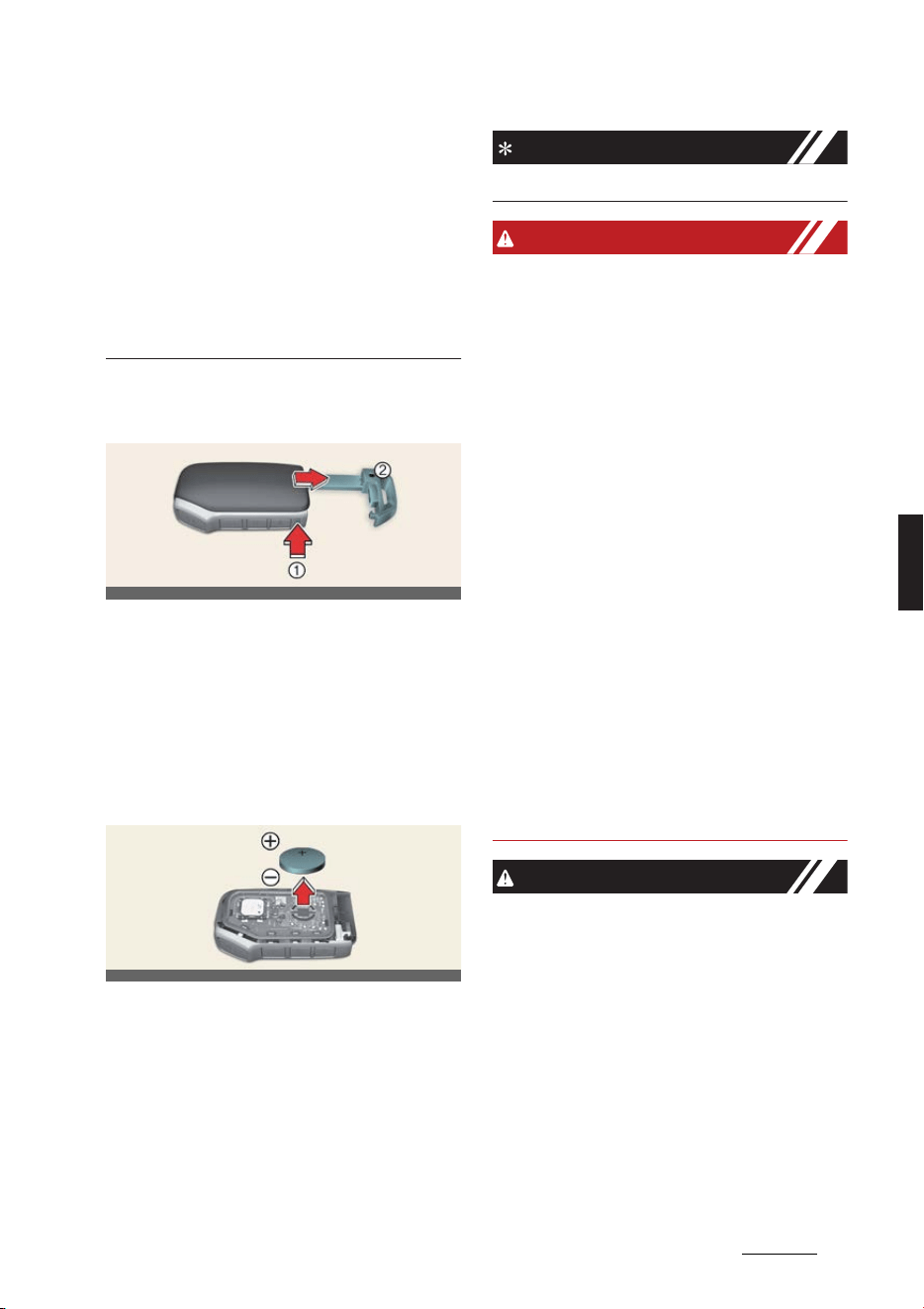
7
5
5
Features of your vehicle Keys
be turned off 10 minutes after starting
the vehicle remotely.
僅 The driver can move the vehicle for
-
ward or backward using the forward/
backward buttons (5, 6) on the smart
key. For more details of Remote Smart
Parking Assist (RSPA), refer to
"Remote Smart Parking Assist (RSPA)
(if equipped)" on page 6-166.
Removing the mechanical key
from the smart key
1
Tab
2
Mechanical key
Operation
1. Press and hold the tab (1).
2. Pull the mechanical key (2) out.
Replacing the key battery
Operation
1. Pry open the key cover gently.
2. Replace the old battery with a new
battery.
INFORMATION
The battery is CR2032 (3V).
WARNING
僅 Never leave the keys in your vehicle
with unsupervised children. Leaving
children unattended in a vehicle with
the Smart key is dangerous even if the
EV button is not in the ACC or ON
position.Children copy adults and they
could press the EV button. The key
would enable children to operate
power windows or other controls, or
even make the vehicle move, which
could result in serious bodily injury or
death.
僅 THIS PRODUCT CONTAINS A BUT
-
TON BATTERY
If swallowed, a lithium button battery
can cause severe or fatal injuries
within 2 hours.
Keep batteries out of reach of chil
-
dren.
If you think batteries may have been
swallowed or placed inside any part of
the body, seek immediate medical
attention.
CAUTION
僅 The smart key is designed to give you
years of trouble-free use, however it
can malfunction if exposed to mois
-
ture or static electricity. If you are
unsure how to use or replace the bat
-
tery, Kia recommends to contact an
authorized Kia dealer/service partner.
僅 Using the wrong battery can cause
the smart key to malfunction. Be sure
to use the correct battery.
OCV041004L
OCV041005L

Features of your vehicle
85
Immobilizer system
僅 To avoid damaging the smart key,
don't drop it, get it wet, or expose it to
heat or sunlight.
僅An inappropriately dis
-
posed battery can be harm
-
ful to the environment and
human health. Dispose the
battery according to your local law(s)
or regulation.
NOTICE
僅 If, for some reason, you happen to
lose your smart key, you will not be
able to start the vehicle. Tow the vehi
-
cle, if necessary, contact a profes
-
sional workshop. Kia recommends to
contact an authorized Kia dealer/ser
-
vice partner.
僅 A maximum of 2 smart keys can be
registered to a single vehicle. If you
lose a smart key, Kia recommends to
contact an authorized Kia dealer/ser
-
vice partner.
僅 When the smart key does not work
properly, open and close the door
with the mechanical key. If you have a
problem with the smart key, Kia rec
-
ommends to contact an authorized
Kia dealer/service partner.
僅 If the smart key is not moved for
some time, the detection function for
smart key operation will pause. Lift
the smart key to activate the detec
-
tion again.
Immobilizer system
The immobilizer system checks, deter
-
mines, and verifies the key whenever the
vehicle is in the ON position.
Whenever the EV button is changed to
the ON position, the immobilizer system
checks and verifies if the key is valid or
not.
If the key is valid, the vehicle will start.
If the key is invalid, the vehicle will not
start.
Vehicles with smart key system
Deactivating the immobilizer sys
-
tem
Operation
僅 Change the EV button to the ON posi
-
tion.
Activating the immobilizer sys
-
tem
Operation
Change the EV button to the OFF posi
-
tion. The immobilizer system activates
automatically. Without a valid smart key
for your vehicle, the vehicle will not start.
WARNING
In order to prevent theft of your vehicle,
do not leave spare keys anywhere in
your vehicle. Your immobilizer password
is a customer unique password and
should be kept confidential. Do not leave
this number anywhere in your vehicle.
CAUTION
僅 Do not put metal accessories near the
EV button. Metal accessories may
interrupt the transponder signal and

9
5
5
Features of your vehicle Theft-alarm system
may prevent the vehicle from being
started.
僅 The transponder in your EV button is
an important part of the immobilizer
system. It is designed to give years of
trouble-free service, however you
should avoid exposure to moisture,
static electricity and rough handling.
immobilizer system malfunction could
occur.
僅Do not change, alter or adjust the
immobilizer system because it could
cause the immobilizer system to mal
-
function. In this case, have the system
serviced by a professional workshop.
Kia recommends visiting an autho
-
rized Kia dealer/service partner.
Malfunctions caused by improper
alterations, adjustments or modifica
-
tions to the immobilizer system are
not covered by your vehicle manufac
-
turer warranty.
僅 Do not attempt to alter this system or
add other devices to it. Electrical prob
-
lems could result that may make your
vehicle inoperable.
NOTICE
僅 When starting the vehicle, do not use
the key with other immobilizer keys
around. Otherwise the vehicle may
not start or may stop soon after it
starts. Keep each key separately in
order to avoid a starting malfunction.
僅 If you need additional keys or lose
your keys, Kia recommends visiting an
authorized Kia dealer/service partner.
Theft-alarm system
Do not attempt to alter this system or
add other devices to it.
Armed stage
Operation
僅 Lock the doors by pressing the lock
button on the key or door handle.
Operating condition(s)
僅 30 seconds after the doors are locked.
僅 Vehicle in OFF position or key
removed from the vehicle.
僅 All doors closed and locked.
Ultrasonic Intrusion Protection
(UIP) (if equipped)
Ultrasonic Intrusion Protection provides
an alert when movement is detected in
the passenger compartment after the
vehicle is locked.
Operation
僅 Select
Settings
→
Vehicle
→
Conve
-
nience
→
Advanced anti-theft
in the
infotainment system screen.
Theft-alarm stage
Operation
僅 The horn will sound and the hazard
warning lights will blink continuously
for approximately 30 seconds. To turn
off the system, unlock the doors with
the smart key.
The system provides an
audible alarm and the haz
-
ard warning lights blink if
triggered. The system is
operated in 3 stages.

Features of your vehicle
105
Theft-alarm system
Operating condition(s)
僅 When Ultrasonic Intrusion Protection
(UIP) is off:
- A front or rear door is opened with
-
out using the smart key.
- The tailgate is opened without
using the smart key.
- The hood is opened.
- The vehicle is in the ON position.
僅 When Ultrasonic Intrusion Protection
(UIP) is on:
- The passenger(s) moves in the
vehicle.
- The inclination of the vehicle is
changed to the certain degree.
- A front or rear door is opened with
-
out using the smart key.
- The tailgate is opened without
using the smart key.
- The hood is closed.
- The vehicle is in OFF position.
Disarmed stage
Operating condition(s)
僅 Door unlock button is pressed.
僅 The vehicle is started.
僅 Outside door handle button is
pressed.
CAUTION
僅 Do not change, alter or adjust the
theft-alarm system because it could
cause the theft-alarm system to mal
-
function. In this case, have the system
serviced by a professional workshop.
Kia recommends visiting an autho
-
rized Kia dealer/service partner.
Malfunctions caused by improper
alterations, adjustments or modifica
-
tions to the theft-alarm system are
not covered by your vehicle manufac
-
turer warranty.
僅 Do not attempt to alter this system or
add other devices to it. Electrical prob
-
lems could result that may make your
vehicle inoperable.
僅 Do not activate the Ultrasonic Intru
-
sion Protection if there are any
chances the vehicle tilts by the out
-
ward influences (for example, ferry
boat traveling, tower parking etc.),
because it could cause the siren to
sound inadvertently.
僅 Make sure all windows are close whilst
the system operates. If not, the Ultra
-
sonic Intrusion Protection detects the
inadvertent movement inside the
vehicle (for example, blowing a wind
or entering a butterfly) and it makes
the siren sounds.
僅 If boxes are piled high in the vehicle,
the Ultrasonic Intrusion Protection
may not detect the movement behind
the boxes. Also the boxes may drop
and it makes the siren sounds.
僅 If the Ultrasonic Intrusion Protection is
stained with foreign matter such as
cosmetics, spray type air freshener, or
spray type window cleaner, the sensor
may not operate normally.
NOTICE
僅 Ultrasonic Intrusion Protection is in
ON position whenever the vehicle is
started again.
僅 Avoid trying to start the vehicle while
the alarm is activated. If the system is
not disarmed with the key, turn the
vehicle to the ON position and wait for
30 seconds. Then the system will be
disarmed.
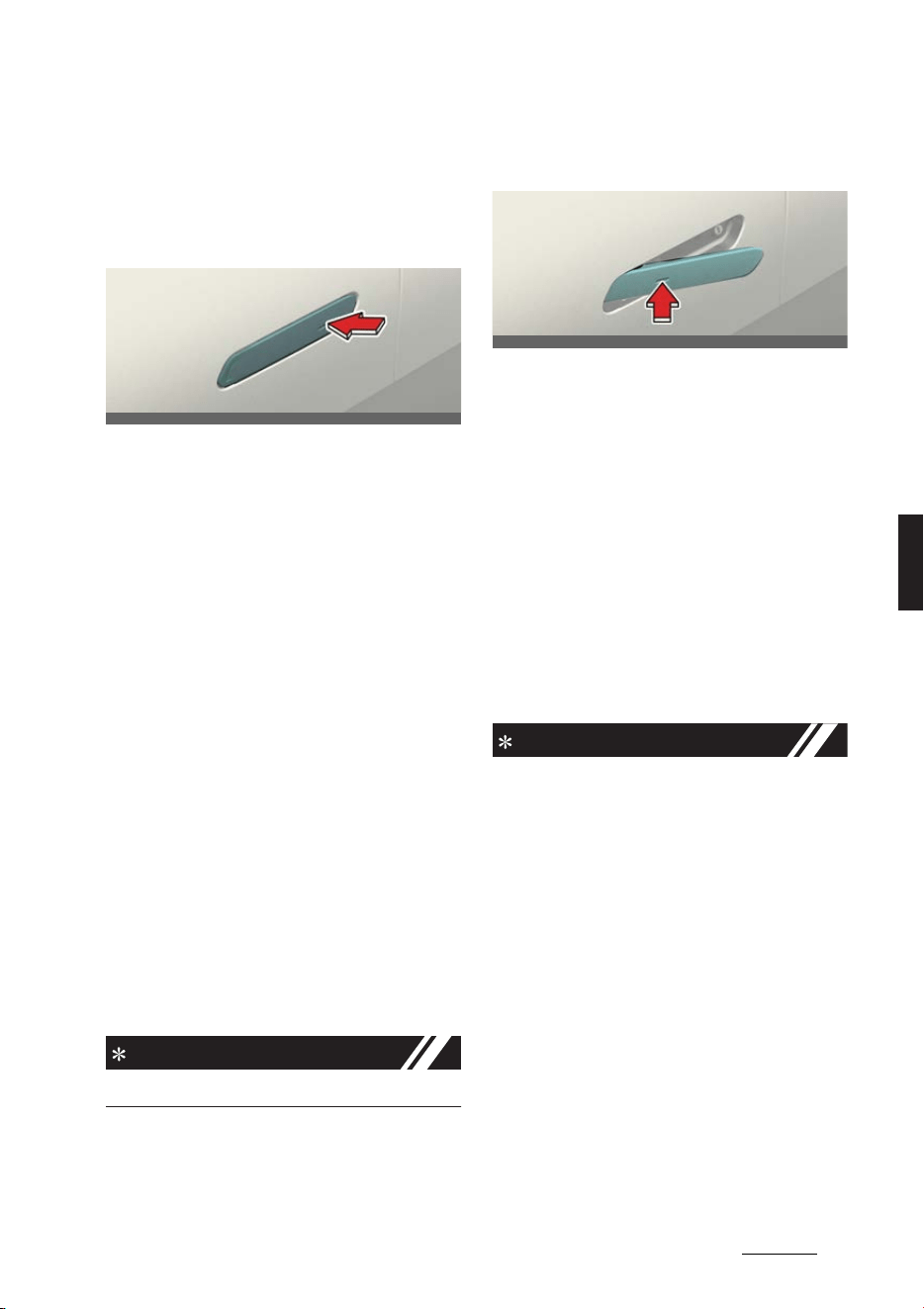
11
5
5
Features of your vehicle Door locks
Door locks
Door locks outside the vehicle
Locking/unlocking with the smart
key (Manual type)
Operation
僅 Press the front door handle button
(driver's side).
僅 Hazard warning lights will blink.
-Locking: Once
- Unlocking: Twice
僅 In addition, pushing the button on the
door handle (the engraved part) while
keeping the smart key will lock all
doors.
Non-operating condition(s)
僅 Smart key is in the vehicle.
僅 The vehicle is in the ACC or ON posi
-
tion.
僅 Any of the doors are open except for
the tailgate.
Limitation(s)
僅 Smart key is detected within 0.7~1 m
radius (28~40 inches).
INFORMATION
The chime will sound for 3 seconds.
Locking/unlocking with the smart
key (Electric type) (if equipped)
The outside door handle will slide out
and the doors will unlock when the
driver approaches the vehicle possess
-
ing the smart key. (Approach unlock sys
-
tem)
Operation
1. Select
Settings
→
Vehicle
→
Door
→
Approach unlock
in the infotainment
system screen.
2. The outside door handle will pop out
and the door will unlock when the
driver approaches the vehicle pos
-
sessing the smart key.
INFORMATION
僅 The driver can activate/deactivate the
Approach unlock system on the info
-
tainment screen.
僅 In emergency situations, such as bat
-
tery is dead, the outside electric door
handle can still be operated in a way
that the outside manual door handle
operate.
僅 If Approaching unlock system is deac
-
tivated, the door handle will not pop
out even when the driver approaches
to the vehicle with the smart key. To
unlock doors when Approach unlock
system is deactivated, touch the lock/
unlock sensor on the handle.
僅 Press the lock button on the smart
key and hold the lock and unlock but
-
ton simultaneously for more than
OCV041583L
OCV041085L
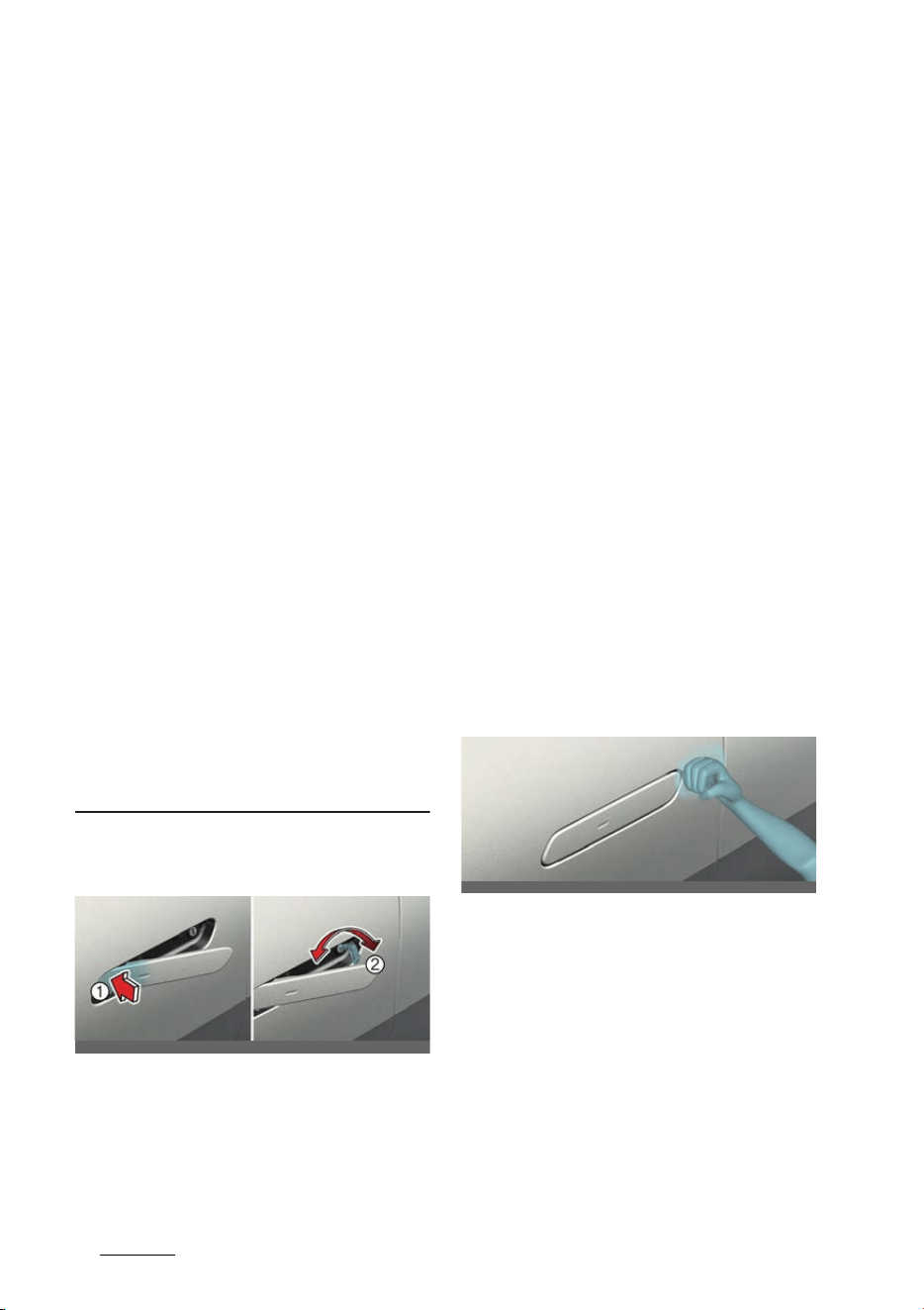
Features of your vehicle
125
Door locks
approximately 4 seconds to prevent
unintentional door lock/unlock. The
hazard warning lights will blink 4
times. The doors will not lock or
unlock even though the touch sensor
is touched on the outside door handle.
Press the door lock or unlock button
on the smart key to deactivate the
function.
僅 When washing the vehicle
-Self car wash
Keep the door locked with the out
-
side door handle closed. To keep
the door unlocked, push back the
outside door handle by hand. This
function prevents the door handle
from being damaged, and the door
handle pops out again when the
unlock button is pressed.
-Auto car wash
Keep the door locked with the out
-
side door handle closed. If the
smart key is not in the vehicle, turn
off the vehicle and stay the smart
key away at least 2 m (78 inches)
from the vehicle to prevent the out
-
side door handle operates.
Locking/unlocking with mechani
-
cal key
1
Tab
2
Key
Operation
1. Press the front part (1) of the door
handle to pull out the rear part of the
door handle.
2. Insert the key with the sharp edge
side on the ground direction (2). The
surface of the panel can be damaged
if it's on opposite direction.
3. Turn the key.
僅 Locking: Left
僅 Unlocking: Right
How to remove ice from door
handles
In extreme winter conditions, the door
handle may not open due to icing inside
the door handle. You can usually use the
bottom of your fist to tap the door han
-
dle a few times to remove the ice.
1. Remove icing by tapping the door
handle using the bottom of your fist in
a circular pattern along the perimeter
of the door handle.
2. If necessary, increase the intensity of
tapping to remove ice, and repeat
until the door handle protrudes when
unlocking the door.
3. When the door handle protrudes and
can be pulled, open and close a few
times to remove any icing residue.
OCV041007L_2
OCV041637N
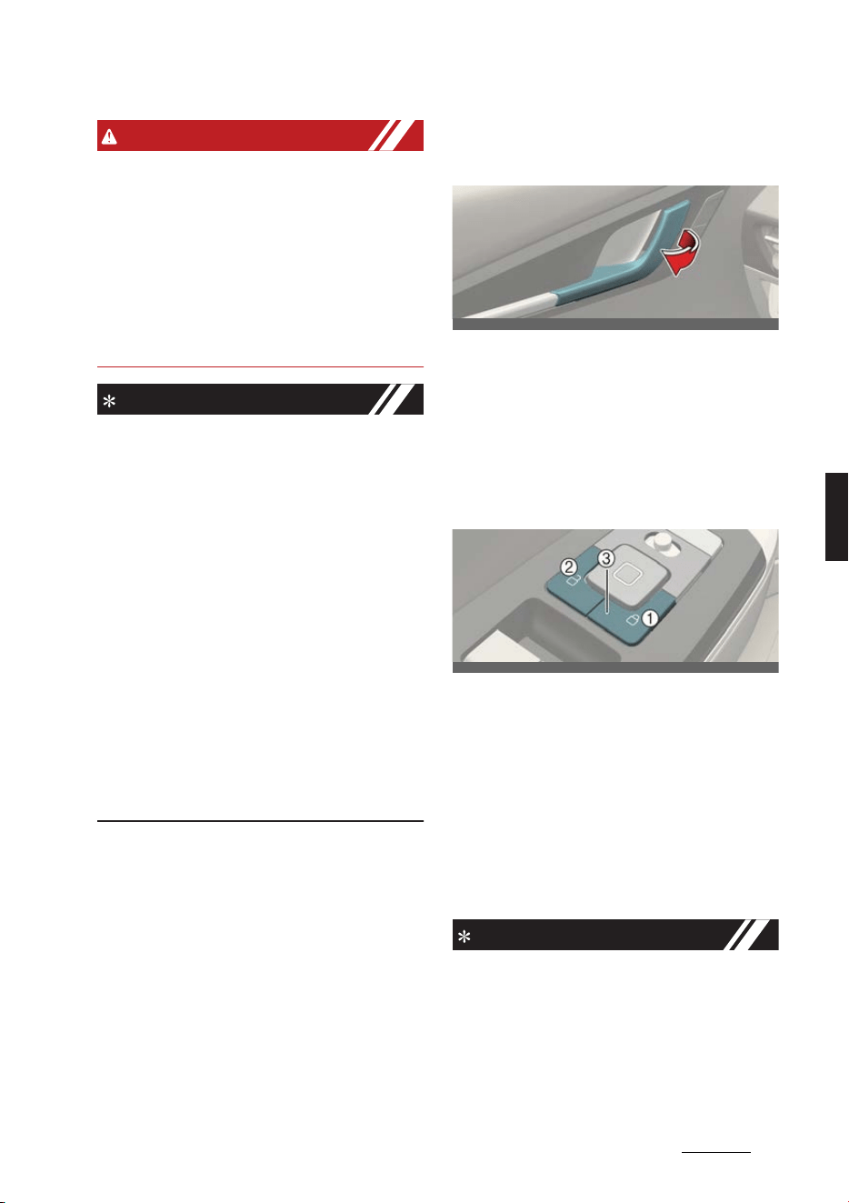
13
5
5
Features of your vehicle Door locks
WARNING
僅 Before performing this procedure,
remove any jewelry or objects that
could damage the paintwork and do
not attempt to use tools or excessive
force.
僅Do not hit the vehicle too hard as
dents may occur. You should use a
force similar to knocking on your
neighbor's door.
NOTICE
僅 When locking the door with a
mechanical key, be aware that only
the driver's door can be locked/
unlocked.
僅 To lock all doors, operate the central
lock switch inside the vehicle. Open
the car door using the inner handle,
then close the door and lock the
driver's door with a mechanical key.
僅 Refer to "Door locks inside the vehicle"
on page 5-13 to lock from inside the
vehicle.
僅 Be careful not to lose or scratch the
door handle.
僅 Do not apply excessive force to the
door and door handle. It may be dam
-
aged.
Door locks inside the vehicle
Unlocking with the door handle
Operation
僅 Pull the door handle.
- Front door: Once
- Rear door: Twice
Locking/unlocking with the cen
-
tral locking switch
1
Door lock button
2
Door unlock button
3
Door indicator light
Operation
僅 Press the corresponding button
below.
-Button (1): Lock
- Button (2): Unlock
INFORMATION
僅 When all vehicle doors are locked, the
door indicator light (3) on the driver's
door and passenger's door will turn
on. If any door is unlocked, it would go
off.
僅 If the smart key is in the vehicle and
any door is opened, the doors will not
OCV041008L
OCV041009L

Features of your vehicle
145
Door locks
lock even though the central door lock
switch is pressed.
WARNING
僅 If a power door lock ever fails to func
-
tion while you are in the vehicle, try
one or more of the following tech
-
niques to exit:
- Operate the door unlock feature
repeatedly (both electronic and
manual) while simultaneously pull
-
ing on the door handle.
- Operate the other door locks and
handles, front and rear.
- Lower a front window and use the
mechanical key to unlock the door
from outside.
- Move to the cargo area and open
the tailgate.
僅 Do not pull the inner door handle of
driver's (or passenger's) door while
the vehicle is moving.
僅 The doors should always be fully
closed and locked while the vehicle is
in motion to prevent accidental open
-
ing of the door. Locked doors will also
discourage potential intruders when
the vehicle stops or slows down.
僅 Be careful when opening doors and
watch out for vehicles, motorcycles,
bicycles or pedestrians approaching
the vehicle in the path of the door.
Opening a door when something is
approaching can result in an accident
to cause vehicle damage or serious
injury.
僅 Leaving your vehicle unlocked can
invite theft or possible harm to you or
others from someone hiding in your
vehicle while you are gone. Always
remove the smart key, engage the
parking brake, close all windows and
lock all doors when leaving your vehi
-
cle unattended.
僅 Unattended children, the elderly or
pets
An enclosed vehicle can become
extremely hot, causing death or
severe injury such as heatstroke to
unattended children, the elderly or
pets who cannot escape the vehicle.
When left or trapped in a hot vehicle,
make sure to stay hydrated and avoid
sun exposure through the vehicle’s
windshield. Furthermore, children
might operate features of the vehicle
that could injure them, or they could
encounter other harm, possibly from
someone gaining entry to the vehicle.
Never leave children or animals unat
-
tended in your vehicle.
CAUTION
When you leave your vehicle with the
smart key, make sure to press the but
-
ton on the front door handle or touch
the touch sensor on the front door han
-
dle to lock the doors after close all of the
doors, the hood and the trunk. If you do
not press the button or touch the touch
sensor firmly, the doors might not be
locked so please use caution.
NOTICE
僅 The outside rearview mirror will fold
or unfold if
On door unlock
is
selected from the Settings menu in
the infotainment system screen.
Select:
-
Settings
→
Vehicle
→
Conve
-
nience
→
Welcome mirror/light
→
On door unlock
僅 The doors may lock or unlock if the
touch sensor of the outer door handle
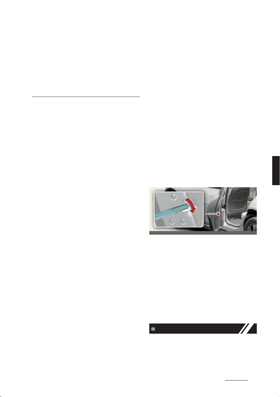
15
5
5
Features of your vehicle Door locks
is recognized while washing your car
or due to heavy rain.
僅 The doors may not lock or unlock in
the following situations:
- If the touch sensor is touched with
gloves on
- If the door is suddenly approached
Automatic door lock and unlock
features
Your vehicle is equipped with features
that will automatically lock or unlock
your vehicle based on settings you
select in the infotainment system screen.
Auto lock enable on speed
When this feature is set in the infotain
-
ment system screen, all the doors will be
locked automatically when the vehicle
exceeds 15 km/h (9 mph).
Auto lock enable on shift
When this feature is set in the infotain
-
ment system screen, all the doors will be
locked automatically when the vehicle is
shifted out of P (Park) while the vehicle
is running.
Auto unlock on shift to P
When this feature is set in the infotain
-
ment system screen, all the doors will be
locked automatically when the vehicle is
shifted out of P (Park) while the vehicle
is running.
Auto unlock vehicle off
When this feature is set in the infotain
-
ment system screen, all the doors will be
unlocked automatically when the vehicle
is turned off.
Impact sensing door unlock sys
-
tem
All doors will automatically unlock when
an impact causes the air bags to deploy.
Additional unlock safety feature
air bag deployment
When this feature is set in the infotain
-
ment system screen, all the doors will be
unlocked automatically when the vehicle
is turned off.
Deadlocks (if equipped)
Some vehicles are equipped with dead
-
lock system. Deadlocks prevent opening
of a door from either inside or outside
the vehicle once the deadlocks have
been activated providing an additional
measure of vehicle security.
To lock the vehicle using the dead lock
function, the doors must be locked by
using the smart key. To unlock the vehi
-
cle, the smart key must be used again.
Manual door lock switch
Operation
1. Open the door.
2. Insert the mechanical key.
3. Turn the key to the lock position.
4. Close the door securely.
Operating condition(s)
僅 The power door lock switch is not
operating.
NOTICE
If the electrical power to door lock switch
is not operating (ex. dead car battery)
and the tailgate is closed, you will not be
OCV041010
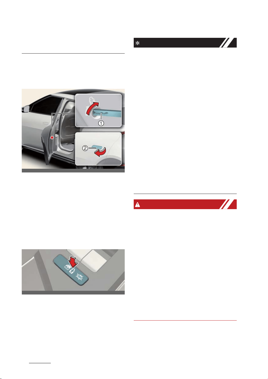
Features of your vehicle
165
Door locks
able to open the tailgate until power is
restored.
Rear door locks
Child-protector rear door lock (if
equipped)
Operation
1. Insert the mechanical key.
2. Turn the child safety lock to the lock
position (1).
3. To open the rear door, pull the outside
door handle (2).
Electronic child safety lock sys
-
tem (if equipped)
Operation
僅 Push the electronic child safety lock
button.
INFORMATION
僅 If you push the electronic child safety
lock switch and the indicator illumi
-
nates, rear passengers cannot open
the rear door from inside the vehicle.
僅 Safe Exit Assist (SEA) does not auto
-
matically activate the electronic child
safety lock system. If your vehicle is
equipped with the Electronic child
safety lock, the child-protector rear
door locks, which are manually oper
-
ated, are not provided.
僅 If 3 minutes passes after the EV but
-
ton is pressed to the OFF or ACC posi
-
tion, the indicator on the button turns
off, and the driver cannot turn off
electronic child safety lock by press
-
ing the button. To turn off the func
-
tion, press the EV button to the ON
position, and then press the electronic
child safety lock button.
WARNING
僅 If children accidentally open the rear
doors while the vehicle is in motion,
they could fall out and be severely
injured or killed. To prevent children
from opening the rear doors from the
inside, the rear door safety locks
should be used whenever children are
in the vehicle.
僅 The system does not detect every
obstacle approaching the vehicle exit.
僅 The driver and passenger are respon
-
sible for the accident occurred while
exiting the vehicle. Always check the
surrounding before you exit the vehi
-
cle.
OCV041011_2
OCV041012L
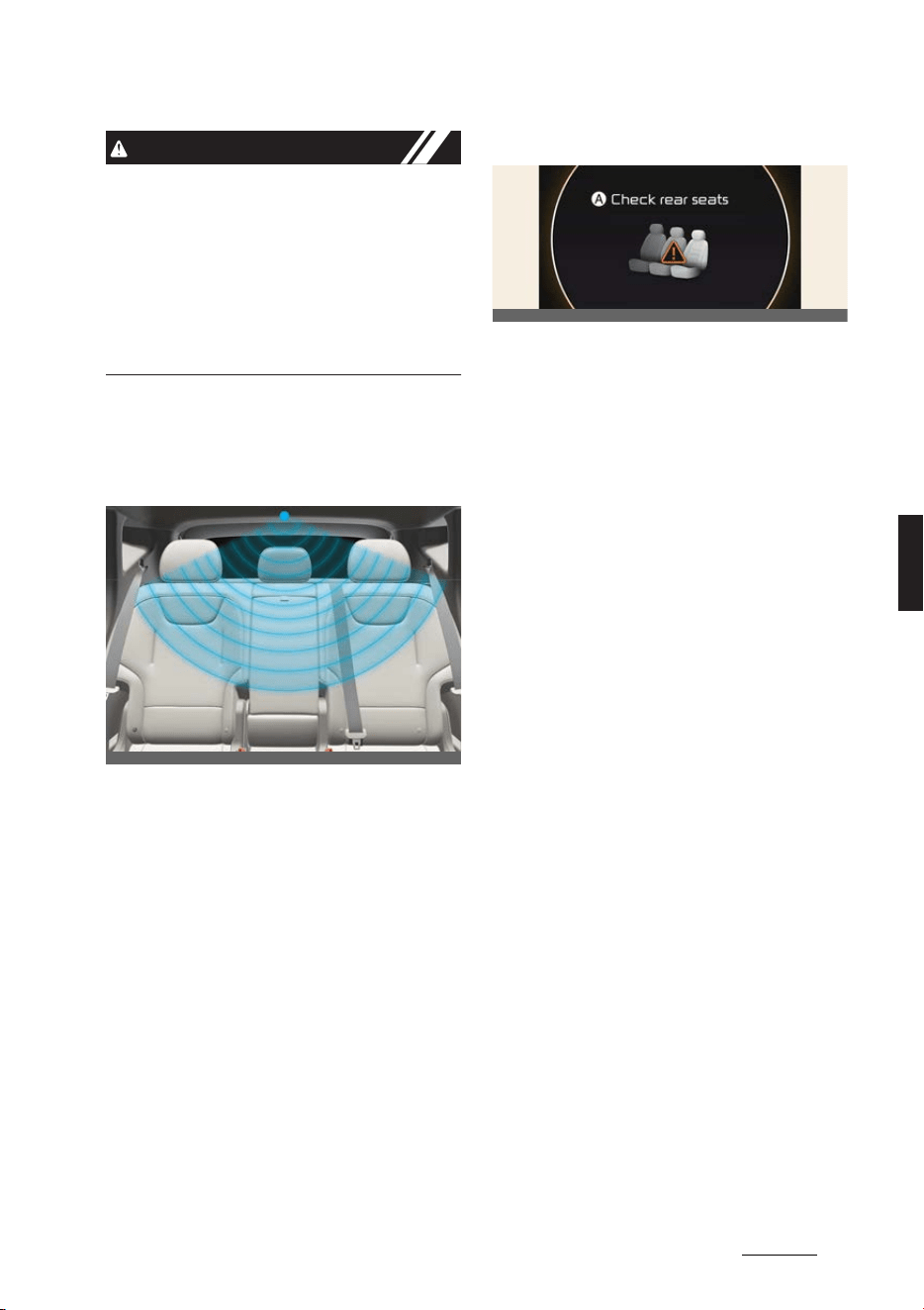
17
5
5
Features of your vehicle Door locks
CAUTION
If the electronic child safety lock is not
operated when pushing the electronic
child safety lock switch, the message is
displayed and the alarm will sound.
If this occurs, have the system checked
by a professional workshop. Kia recom
-
mends visiting an authorized Kia dealer/
service partner.
Rear Occupant Alert (ROA)
The Rear Occupant Alert (ROA) is pro
-
vided to help prevent exiting the vehicle
with a rear passenger left in the vehicle.
Operation
僅 Select
Settings
→
Vehicle
→
Conve
-
nience
→
Rear Occupant Alert
on
the infotainment system screen.
* For detailed information, refer to Navi
-
gation Quick Reference Guide.
1st alert operation
A:
Check rear seats
When you turn off the vehicle and open
the driver's door after opening and clos
-
ing the rear door or tailgate, the warning
message appears on the cluster.
2nd alert operation (if equipped)
After the first alert, the second alert
operates when any movement is
detected in the vehicle after the driver's
door is closed and all the doors are
locked. The horn will sound for approxi
-
mately 25 seconds. Also, a text message
is sent to members of Kia Connect Ser
-
vices (if equipped). If the system contin
-
ues to detect a movement, the alert
operates up to 8 times. Unlock the doors
with the smart key to stop the alert.
The system detects movement in the
vehicle for 10 minutes after the door is
locked.
Rear Occupant Alert (ROA) pre
-
cautions
僅 Make sure that all the windows are
closed. If the window is open, the alert
may operate by the sensor detecting
an unintended movement (e.g. wind
or bugs).
僅 The alert may operate if movement in
the driver or passenger seat is
detected.
僅 If the doors are locked with a passen
-
ger inside the vehicle, the alert may
operate.
OCV051203L
OCV041119L
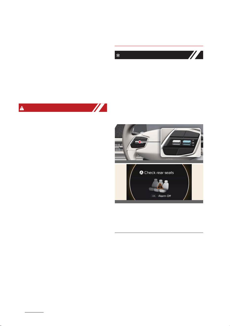
Features of your vehicle
185
Door locks
僅 An alert can occur if the there is an
impact on the vehicle.
僅 If boxes or objects are stacked in the
vehicle, the system may not detect
the boxes or objects. Or, the alert may
operate if the boxes or objects fall off.
僅 The alert may operate with the doors
locked due to car wash or surround
-
ing vibration or noise.
僅 The alert may operate when there are
metallic or liquid objects in the vehicle.
WARNING
Even if your vehicle is equipped with
Advanced Rear Occupant Alert (ROA),
always make sure to check the rear seat
before you leave the vehicle. Advanced
Rear Occupant Alert (ROA) may not
operate when:
僅 Movement does not continue for a
certain period of time or the move
-
ment is small.
僅 A child is not seated in a child restraint
system.
僅 Movement is detected in areas other
than the rear seats.
僅 The rear passenger is covered with a
fabric containing metallic substance
such as a blanket.
僅 An object in the vehicle blocks the
sensor.
僅 The sensor is contaminated by foreign
material.
僅 An animal at the rear seat or luggage
compartment is not large enough to
be detected by the sensor or there is
hardly any movement.
僅 Attaching objects or modifying the
interior ceiling, or the interior ceiling is
deformed or damaged.
僅 There are electronic interference
around the vehicle.
僅 Other environmental reasons that
may affect the system.
NOTICE
僅 The second alert is activated only
after the prior activation of the first
alert.
僅 The second alert activates only when
the sensor is equipped in the vehicle.
僅 If you do not want to use Rear Occu
-
pant Alert, press the OK button on the
steering wheel when the first alert is
displayed on the cluster. Doing so will
deactivate the second alert one time.
A:
Check rear seats
僅 If the vehicle is started remotely (if
equipped with Remote Start), inside
movement detection will stop.
OCV041203L
OCV041120L
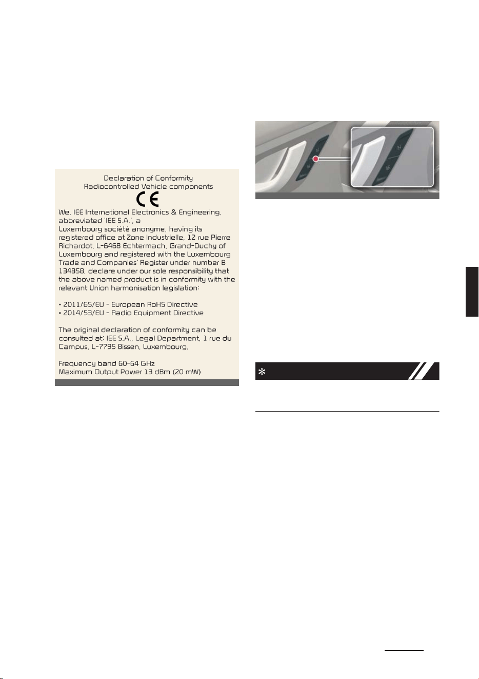
19
5
5
Features of your vehicle Driver position memory system
Declaration of conformity
The radio frequency components
(ROA Radar Sensor) complies:
For Europe and CE certified coun
-
tries
Driver position memory sys
-
tem (if equipped)
Setting memory position
Operation
僅 Adjust the following positions:
- Driver's seat position (if equipped)
- Wing mirror position (if equipped)
- Head-Up Display (HUD): display
mode, position, AR matching
adjustment (if equipped)
僅 Press '1' or '2' button.
- Within approximately 4 seconds
-Chime twice
INFORMATION
The vehicle should be in the ON position
to use this function.
Recalling memory position
Operation
僅 Press the '1' or '2' button.
-Chime once
僅 Stored positions will be adjusted.
OCV052280L
OCV041013L

Features of your vehicle
205
Driver position memory system
Resetting the driver position
memory system
Operation
1. Shift to P (Park) while the EV button is
in the ON position.
2. Move the driver seat as forward as
possible.
3. Move the seatback to a fully upright
position.
4. Press the '1' button and seat forward
movement switch simultaneously for
approximately 2 seconds.
Initialization
僅 The seat and seatback will move
backwards.
-Chime continues
僅 The seat and seatback will move to
the center position.
- Chime stops
Easy access function
Operating condition(s)
僅 Driver's seat moves backward when:
- The vehicle is in the OFF position
- The driver door is opened
僅 Driver's seat moves forward when:
- The vehicle is in the ACC or ON
position
- The driver door is closed when you
have the smart key with you.
INFORMATION
僅 You can activate or deactivate the
Easy Access Function from Vehicle
Settings from the infotainment system
screen. For more details, refer to Navi
-
gation Quick Reference Guide.
WARNING
Never attempt to operate the driver
position memory system while the vehi
-
cle is moving. This could result in loss of
control, and an accident causing death,
serious injury, or property damage.
NOTICE
僅 If the battery is disconnected, the
memory settings will be erased.
僅 If the Driver Position Memory System
does not operate normally, we recom
-
mend that you have the system
checked by an authorized Kia dealer/
service partner.
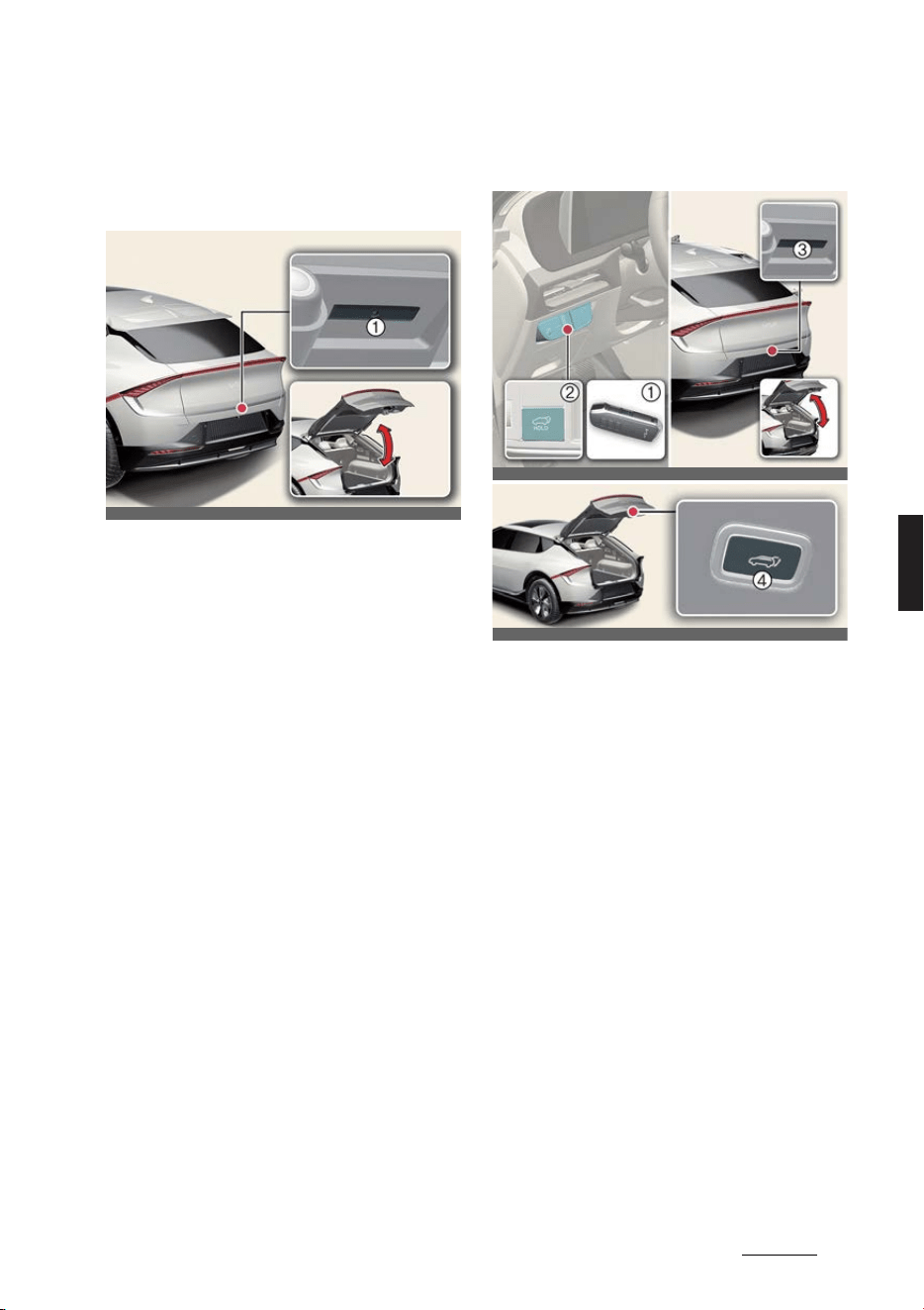
21
5
5
Features of your vehicle Tailgate
Tailgate
Opening/closing the manual tail
-
gate
Operation
1. Press the outside handle switch (1) to
open the tailgate.
2. Pull up the tailgate.
3. Push down the tailgate to close the
tailgate. Make sure that the tailgate is
securely latched.
Operating condition(s)
僅 The tailgate is locked or unlocked
using the key or central door lock
switch.
Opening/closing the power tail
-
gate (if equipped)
Operation
僅 Power tailgate open/close button -
smart key (1)/inside the vehicle (2)
When the tailgate is closed, press and
hold the power tailgate open/close
button. The tailgate will open auto
-
matically and the warning chime will
sound. Press the tailgate open/close
button again to stop the operation.
When the tailgate is opened, press
and hold the power tailgate open/
close button. The tailgate will close
automatically and the warning chime
will sound. Press the power tailgate
open/close button until the tailgate is
closed completely. If the tailgate
open/close button is not pressed
while closing, power tailgate will stop
operate and warning chime will sound
for approximately 5 seconds.
OCV041016L_2
OCV041017K_4
OCV041019K
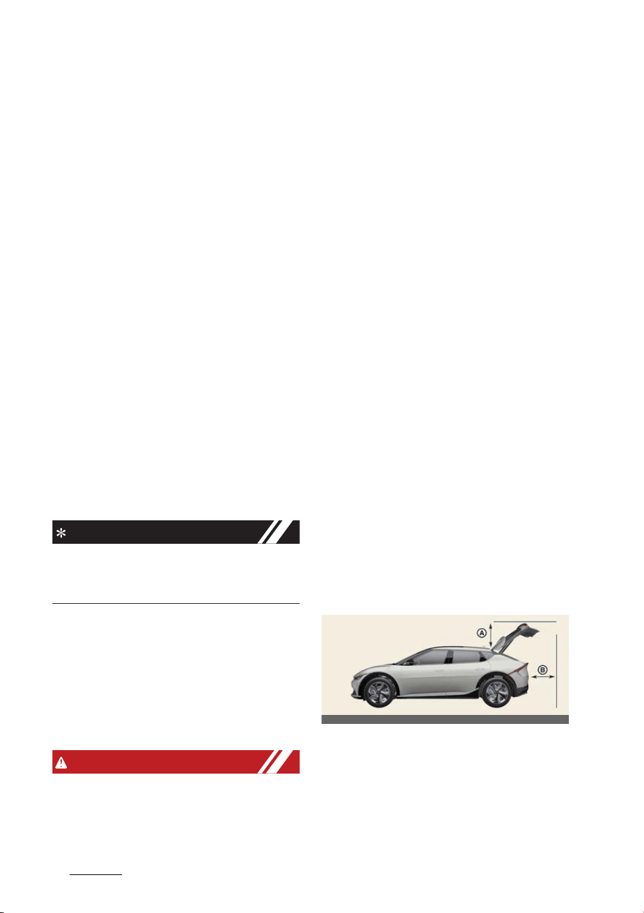
Features of your vehicle
225
Tailgate
僅 Power tailgate open button - out
-
side the vehicle (3)
When the smart key is detected, press
the power tailgate open button. The
tailgate will open and the warning
chime will sound. If the doors are
unlocked, the tailgate can be opened
or closed without the smart key.
僅 Power tailgate close button - inside
the vehicle (4)
Press the power tailgate close button.
The tailgate will close and the warning
chime will sound.
Operating condition(s)
僅 The vehicle is in the ON position and
the vehicle gear is in P (Park).
僅 The vehicle is in OFF position.
僅 Smart key is carried.
Non-operating condition(s)
僅 Vehicle speed is above 3 km/h (2
mph).
INFORMATION
Only the power tailgate opening will not
operate if the vehicle speed is above 3
km/h (2 mph).
Power tailgate automatic reversal
The power tailgate will open again auto
-
matically if the power tailgate is blocked
by an object or a part of the body.
If the resistance is detected while open
-
ing and closing the tailgate, it will stop
and move in the opposite direction.
WARNING
僅 Make sure the vehicle is in P (Park)
and set the parking brake.
僅 Occupants should never ride in the
rear cargo area where no restraints
are available. To avoid injury in the
event of an accident or sudden stops,
occupants should always be properly
restrained.
僅 The tailgate swings upward. Make
sure no objects or people are near the
rear of the vehicle when opening the
tailgate.
僅 Make sure your hands, feet and other
parts of your body are safely out of
the way before closing the tailgate.
僅 Never leave children or animals unat
-
tended in your vehicle. Children or
animals might operate the power tail
-
gate that could result in injury to
themselves or others, or damage the
vehicle.
僅 Make sure there are no people or
objects around the tailgate before
opening or closing the power tailgate.
Wait until the tailgate is open fully and
stopped before loading or unloading
cargo from the vehicle.
僅 Make sure that there are no people or
objects in the path of the power tail
-
gate (or smart tailgate) prior to use.
Serious injury, damage to the vehicle
or damage to surrounding objects
may result if contact with the power
tailgate (or smart tailgate) occurs.
-A: 70 cm
-B: 70 cm
僅 The chime will sound continuously if
you drive over 3 km/h (2 mph) with
the tailgate opened. Stop your vehicle
OCV041018L

23
5
5
Features of your vehicle Tailgate
immediately at a safe place and check
if your tailgate is opened.
僅 Never intentionally place any object or
part of your body in the path of the
power tailgate to make sure the auto
-
matic reversal operates.
僅 Never operate power tailgate
attached with any heavy objects (ex.
bicycles). It could damage the power
tailgate.
CAUTION
僅 Make certain that you close the tail
-
gate before driving your vehicle. Pos
-
sible damage may occur to the
tailgate gas lifters and attached hard
-
ware if the tailgate is not closed prior
to driving.
僅 Make sure nothing is near the tailgate
latch and striker while closing the tail
-
gate. It may damage the tailgate's
latch.
僅 Be careful when opening and closing
the tailgate or inserting and removing
objects, as body or objects may be
injured or damaged if they are hit by
sharp edges, such as corners. Chil
-
dren may get hurt if their face, head,
etc. hit the area around the tailgate, so
always be aware.
僅 Do not close or open the power tail
-
gate manually. This may cause dam
-
age to the power tailgate. If it is
necessary to close or open the power
tailgate manually when the battery is
discharged or disconnected, do not
apply excessive force.
僅 Do not operate the power tailgate
more than 5 times continuously. It
may damage the power tailgate sys
-
tem. If the spindle is strained due to
continuous operation, the chime will
sound 3 times and the power tailgate
will not operate. At this time, stop
operating the tailgate and leave it for
more than 1 minute.
NOTICE
僅 Do not put heavy stuffs on the power
tailgate when you operate the power
tailgate. Additional weight on tailgate
could cause damages to the system.
僅 If The vehicle is in the ON position, the
power tailgate can operate when P
(Park) gear position is selected.
僅 The power tailgate can be operated
when the vehicle is not running. How
-
ever the power tailgate operation con
-
sumes large amounts of vehicle
electric power. To prevent the battery
from being discharged, do not oper
-
ate it excessively e.g. more than
approximately 10 times repeatedly.
僅 To prevent the battery from being dis
-
charged, do not leave the power tail
-
gate in the open position for a long
time.
僅 Do not modify or repair any part of
the power tailgate by yourself. Kia
recommends visiting an authorized
Kia dealer/service partner.
僅 When jacking up the vehicle to
change a tire or repair the vehicle, do
not operate the power tailgate. This
could cause the power tailgate to
operate improperly.
僅 In cold and wet climates, the power
tailgate may not work properly due to
freezing conditions.
僅 In cold and wet climates, door lock
and door mechanisms may not work
properly due to freezing conditions.
僅 Power tailgate may stop operating
when more than one operation is
detected while opening/closing. In this

Features of your vehicle
245
Tailgate
case, open/close the tailgate manually
and operate the power tailgate func
-
tion.
Setting power tailgate
Operation
僅 Select
Settings
→
Vehicle
→
Door
→
Power tailgate
on infotainment sys
-
tem.
Adjusting power tailgate speed
Operation
僅 Select
Settings
→
Vehicle
→
Door
→
Power tailgate opening speed
→
Normal
/
Fast
on the infotainment sys
-
tem.
僅 The initial setting is set to
Fast
.
Adjusting power tailgate open
-
ing height
Operation
僅 Select
Settings
→
Vehicle
→
Door
→
Power tailgate opening height
→
Level 1
/
Level 2
/
Level 3
/
Full open
/
User height setting
on infotainment
system.
Adjusting User Height Setting
Operation
1. Adjust the tailgate to the preferred
height.
2. Press the power tailgate close button
for approximately 3 seconds until the
alarm is heard.
NOTICE
僅 If the tailgate opening height is
adjusted manually, the settings for the
infotainment system will change to
User height setting
.
僅 The tailgate opening height will be
same as
Full open
before
User
height setting
is set.
僅If
User height setting
is selected
after
Full open
/
Level 3
/
Level 2
/
Level
1
, the previous user height setting will
be set.
Resetting the power tailgate
Operation
1. Turn the vehicle OFF or shift to P
(Park) or N (Neutral).
2. Press the power tailgate open button
to open the power tailgate.
3. Press and hold the inside tailgate
close button first and outside tailgate
open button simultaneously for more
than 3 seconds and the chime will
sound.
4. Close the tailgate manually.
5. Press the power tailgate open button
on the outside of the vehicle.
6. The tailgate will open and the chime
will sound.
7. If the tailgate is stopped before it is
fully open, resetting will not proceed.
Wait until the tailgate is open fully and
stopped.
Operating condition(s)
僅 Vehicle is in P (Park) position.
NOTICE
僅 If the power tailgate does not operate
normally, check again if the gear is in
the correct position.
僅 The power tailgate needs to be reset
in following conditions:
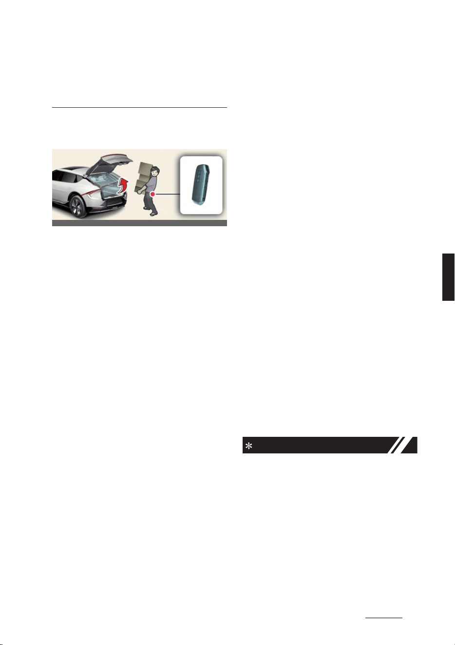
25
5
5
Features of your vehicle Tailgate
- The battery (12V) is recharged
- The battery (12V) is reassembled
- Related fuse is reassembled
Opening the smart tailgate (if
equipped)
Operation
僅 Select
Settings
→
Vehicle
→
Door
→
Smart tailgate
on the infotainment
system.
Operating condition(s)
僅 After 15 seconds when all doors are
closed and locked.
僅 Positioned in the detecting area for
more than 3 seconds.
僅 Disconnecting the charging connector
Non-operating condition(s)
僅 The Smart Key is detected less than 15
seconds after the doors are closed
and locked and is continuously
detected.
僅 The Smart Key is detected less than 15
seconds after the doors are closed
and locked and 1.5 m from the front
door handles (for vehicles equipped
with Welcome Light).
僅 A door is not locked or closed.
僅 The smart key is in the vehicle.
僅 The vehicle is on charge
Limitation(s)
僅 Smart key is not detected within
50~100 cm (28~40 inches) radius
behind the vehicle
Detect and Alert
Operation
僅 The hazard warning lights will flash.
僅 The alarm will sound when the smart
key is detected.
Automatic opening
Operation
僅 The tailgate will open.
僅 The hazard warning lights will flash.
僅 The alarm will sound 6 times.
Deactivating smart tailgate with
smart key
Operation
僅 Press any of the following smart key
buttons during "Detect and Alert"
stage to deactivate the function.
- Door lock button
- Door unlock button
- Tailgate open/close button
NOTICE
僅 If you press the door unlock button,
the Smart Tailgate with Auto Open
function will be deactivated temporar
-
ily. But, if you do not open any door
for 30 seconds, the Smart Tailgate
with Auto Open function will be acti
-
vated again.
僅 If you press the tailgate open button
for more than 1 second, the tailgate
opens.
OCV041020L

Features of your vehicle
265
Tailgate
僅 If you press the door lock button or
tailgate open button when the Smart
Tailgate with Auto Open function is
not in the Detect and Alert stage, the
Smart Tailgate with Auto Open func
-
tion will not be deactivated.
僅 In case you have deactivated the
Smart Tailgate with Auto Open func
-
tion by pressing the smart key button
and opened a door, the Smart Tail
-
gate with Auto Open function can be
activated again by closing and locking
all doors.
Non-operating condition(s)
僅 The smart key is close to a radio
transmitter such as a radio station or
an airport, which can interfere with
the normal operation of the smart
key.
僅 The Smart Key is near a mobile two-
way radio system or a cell phone.
僅 Another vehicle's smart key is being
operated close to your vehicle.
僅 The detecting range may decrease or
increase when:
- One side of the vehicle is raised to
replace a tire or to inspect the vehi
-
cle.
- The vehicle is parked at a slant on a
slope, an unpaved road, etc.
WARNING
僅 Make sure you close the tailgate
before driving your vehicle.
僅 Make sure there are no people or
objects around the tailgate before
opening or closing the tailgate.
僅 Make sure objects in the tailgate do
not come out when opening the tail
-
gate on a slope. It may cause serious
injury.
僅 Make sure to deactivate the Smart
Tailgate with Auto Open when wash
-
ing your vehicle. Otherwise, the tail
-
gate may open inadvertently.
僅 The key should be kept out of reach
of children. Children may inadver
-
tently open the Smart Tailgate with
Auto Open while playing around the
rear area of the vehicle.
CAUTION
Do not approach the detecting area if
you do not want the tailgate to open. If
you have unintentionally entered the
detecting area and the hazard warning
lights and chime starts to operate, leave
the detecting area with the smart key.
The tailgate will stay closed.
NOTICE
僅 If the power tailgate opening height is
set manually, and then
User height
setting
is selected from the infotain
-
ment system, the power tailgate will
automatically open to the height man
-
ually set by the driver.
僅 If the power tailgate opening height
has not been manually set, the power
tailgate will fully open when
User
height setting
from the infotainment
system is selected.
僅 If one of the height (
Full open
/
Level
3
/
Level 2
/
Level 1
) is selected from
the settings menu in the infotainment
system screen, and then
User height
setting
is selected, the power tailgate
open height will be set to the previ
-
ously saved height.
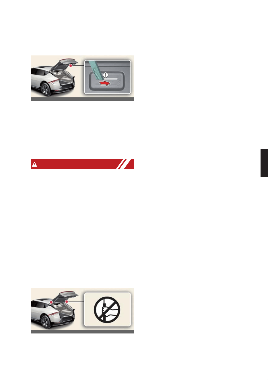
27
5
5
Features of your vehicle Tailgate
Tailgate emergency safety
release
Operation
1. Insert the mechanical key into the
keyhole.
2. Move the mechanical key to the right
(1).
3. Push the tailgate upward.
WARNING
僅 For emergencies, be fully aware of the
location of the emergency tailgate
safety release lever in the vehicle and
how to open the tailgate if you are
accidentally locked in the luggage
compartment.
僅 No one should be allowed to occupy
the cargo area of the vehicle at any
time. The cargo area is a very danger
-
ous location in the event of a crash.
僅 Use the release lever for emergencies
only. Use with extreme caution, espe
-
cially while the vehicle is in motion.
僅 Do not grasp the part supporting the
tailgate (gas lifter), as this may cause
serious injury.
OCV041021L
OCV041022L
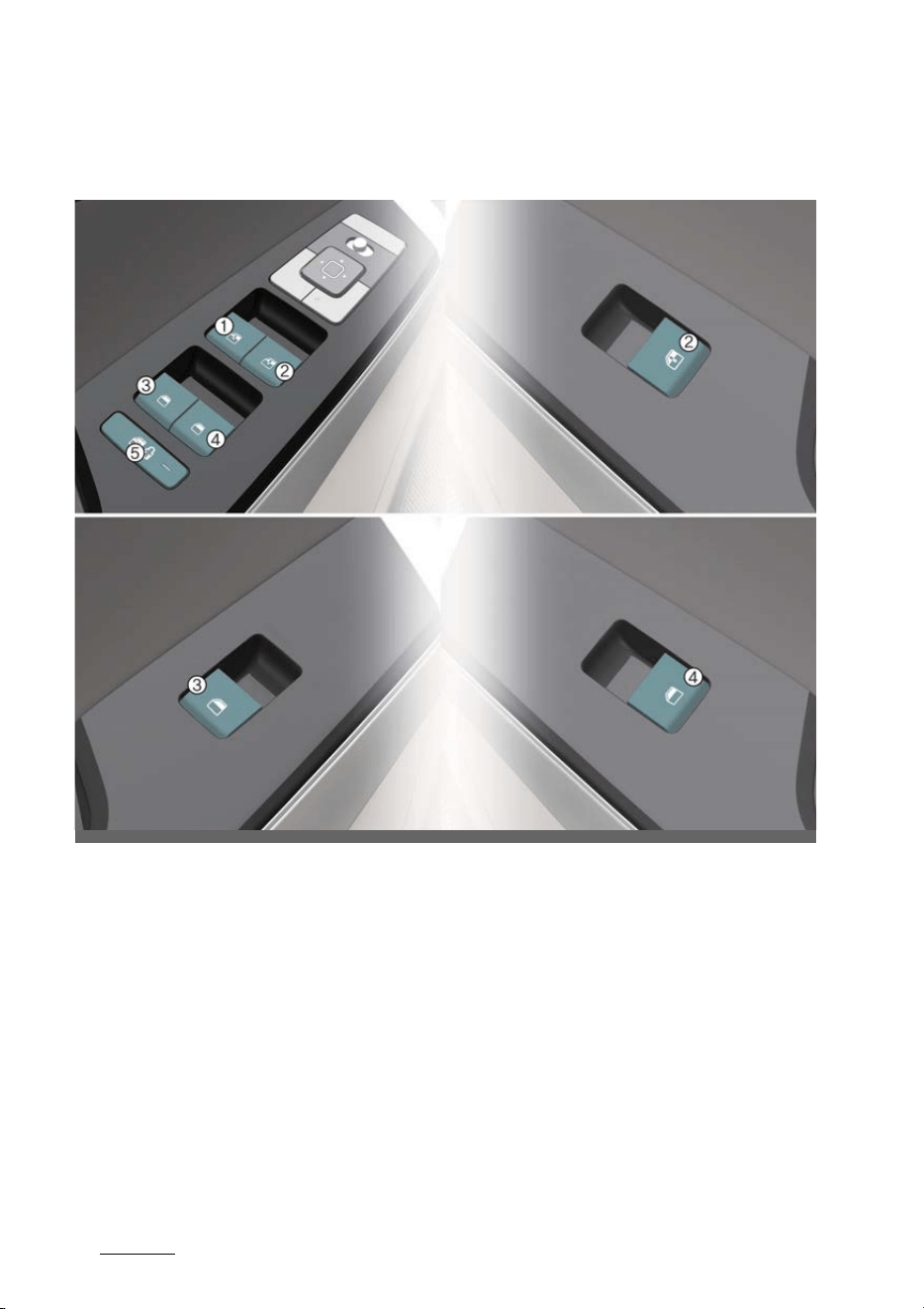
Features of your vehicle
285
Windows
Windows
Left-hand drive
OCV041023L_4
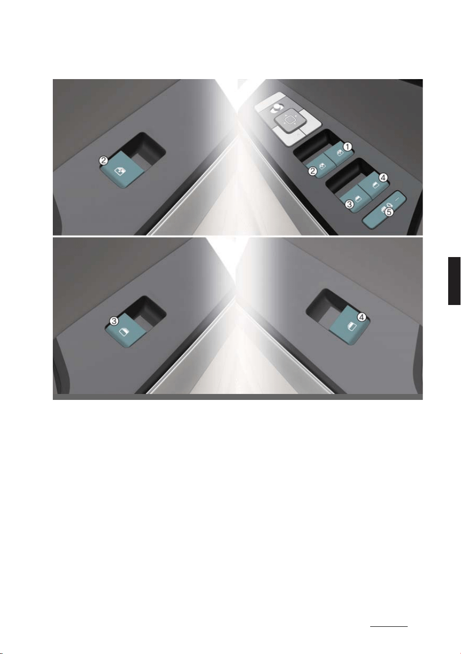
29
5
5
Features of your vehicle Windows
Right-hand drive
1
Driver's door power window switch
2
Front passenger's door power window switch
3
Rear door (left) window switch
4
Rear door (right) window switch
5
Power window lock switch
OCV041023R_4
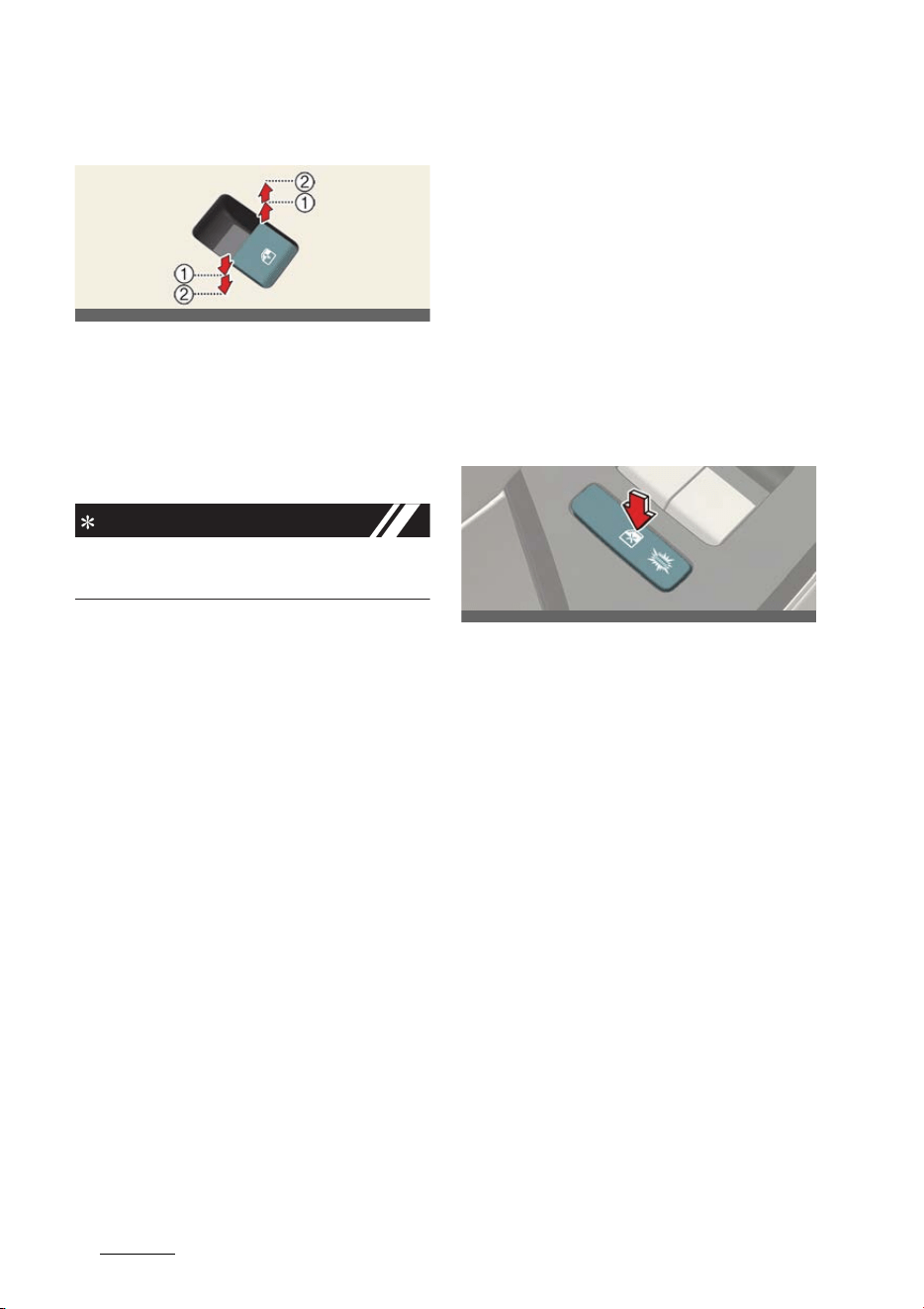
Features of your vehicle
305
Windows
Controlling windows switch
僅Type A: 1
僅 Type B (if equipped): 1, 2
Operation
僅 Press or pull the switch to the first (1)/
second (2) detent position.
INFORMATION
Only type B can use auto up/down func
-
tion (2).
Operating condition(s)
僅 The vehicle is in the ON position
僅 Within approximately 3 minutes after
EV button turned to the ACC position.
However, if the front doors are
opened, the power windows cannot
be operated even within the 3 min
-
utes period.
Resetting the power windows
Operation
1. Close the window.
2. Pull the power window switch.
僅Approximately 1 second
Operating condition(s)
僅 The vehicle is in the ON position.
Power windows automatic rever
-
sal
Operation
僅 Windows will stop and move down
approximately 30 cm (12 inches)
when an object or body part is
detected.
僅 Windows will move down approxi
-
mately 2.5 cm (1 inches) when the
force is detected.
Power windows lock button
Operation
僅 Push the power windows lock button.
- Rear passenger window is inopera
-
ble.
僅 The front driver and passenger win
-
dow can be operated.
僅 The rear passengers' control cannot
operate the rear passenger's power
window.
Remote window closing/opening
(if equipped)
Operation
僅 Press and hold the door lock button
on the smart key to close the win
-
dows. The windows will move up as
long as the button is pressed.
僅 Press and hold the door unlock button
on the smart key to open the win
-
dows. The windows will move down as
long as the button is pressed.
OCV041024L
OCV041025L

31
5
5
Features of your vehicle Windows
僅 Remote window operation can be
activated or deactivated through the
infotainment system menu.
WARNING
僅 Do not install any accessories in the
area of windows. It may impact jam
protection.
僅 Always check for obstructions before
raising any window to avoid injuries or
vehicle damage. If an object less than
4 mm (0.16 inches) in diameter is
caught between the window glass and
the upper window channel, the auto
-
matic reverse window may not detect
the resistance and will not stop and
reverse direction.
僅 The automatic reverse feature is not
activated while resetting power win
-
dow system. Make sure body parts or
other objects are safely out of the way
before closing the windows to avoid
injuries or vehicle damage.
僅 NEVER leave the keys in your vehicle
with unsupervised children, when the
vehicle is running.
僅 NEVER leave any child unattended in
the vehicle. Even very young children
may inadvertently cause the vehicle
to move, entangle themselves in the
windows, or otherwise injure them
-
selves or others.
僅 Always double check to make sure all
arms, hands, head and other obstruc
-
tions are safely out of the way before
closing a window.
僅 Do not allow children play with the
power windows. Keep the driver's
door power window lock button in the
LOCK position (pressed). SERIOUS
INJURY can result from unintentional
window operation by the child.
僅 Do not extend heads or any limbs out
-
side the window while the vehicle is in
motion.
僅 Make sure body parts of other objects
are safely out of the way before
remote closing the windows to avoid
injuries or vehicle damage.
CAUTION
僅 To prevent possible damage to the
power window system, do not open or
close two windows or more at the
same time. This will also ensure the
longevity of the fuse.
僅 Never try to operate the main switch
on the driver's door and the individual
door window switch in opposite direc
-
tions at the same time. If this is done,
the window will stop and cannot be
opened or closed.
NOTICE
僅 While driving with the rear windows
down or with the sunroof (if
equipped) in an open (or partially
open position), your vehicle may
demonstrate a wind buffeting or pul
-
sation noise. This noise is a normal
occurrence and can be reduced or
eliminated by taking the following
actions. If the noise occurs with one or
both of the rear windows down, par
-
tially lower both front windows
approximately one inch. If you experi
-
ence the noise with the sunroof open,
slightly reduce the size of the sunroof
opening.
僅 In cold and wet climates, power win
-
dows may not work properly due to
freezing conditions.
僅 The automatic reverse feature for the
window is only active when the "auto
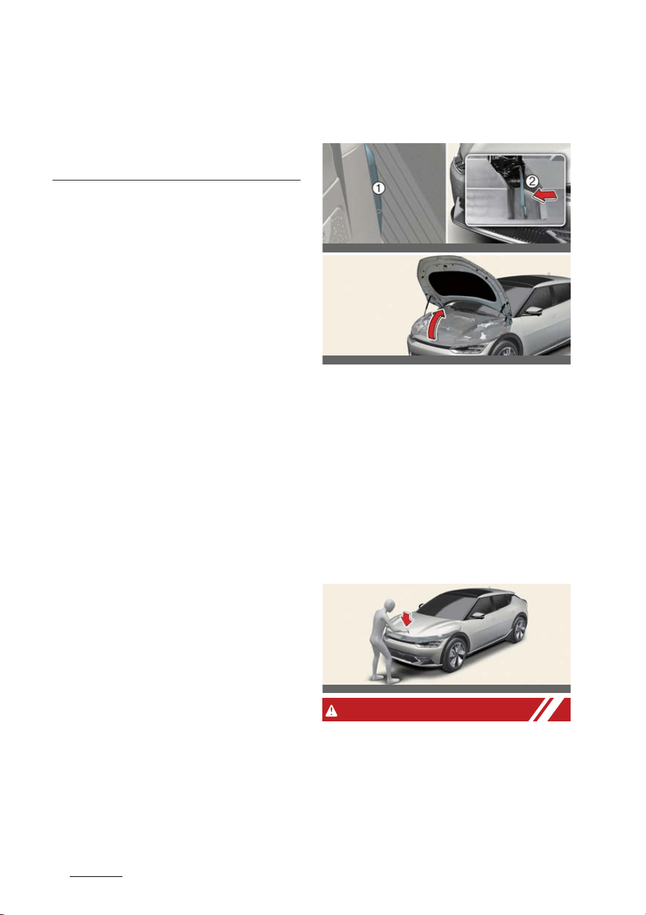
Features of your vehicle
325
Hood
up" feature is used by fully pulling up
the switch. The automatic reverse fea
-
ture will not operate if the window is
raised using the halfway position on
the power window switch.
Hood
Opening/closing the hood
1
Hood release lever
2
Hood secondary latch
Operation
1. Pull the hood release lever (1).
2. Push the secondary latch (2) to the
left.
3. Lift the hood upwards.
4. To close the hood, lower the hood and
let it drop. Make sure that it is prop
-
erly locked into place.
WARNING
僅 Open the hood after turning off the
vehicle on a flat surface, shifting the
gear to the P (Park) position and set
-
ting the parking brake.
僅 Before closing the hood, ensure that
all obstructions are removed from the
hood opening. Closing the hood with
OCV041026L_2
OCV041589
OCV041590
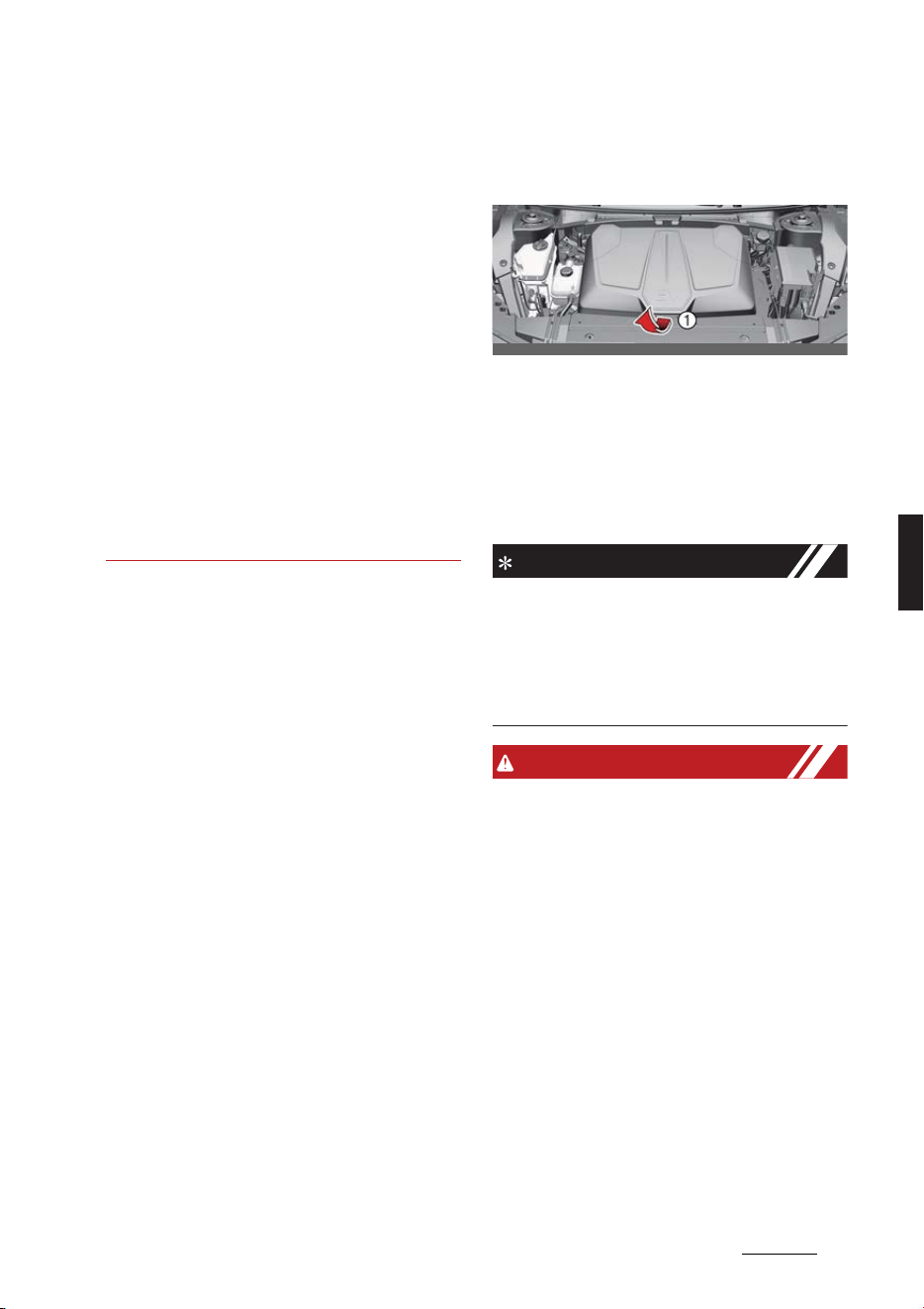
33
5
5
Features of your vehicle Front trunk
an obstruction present in the hood
opening may result in property dam
-
age or severe personal injury.
僅 Do not leave gloves, rags or any other
combustible material in the motor
compartment. Doing so may cause a
heat-induced fire.
僅 Always double check to be sure that
the hood is firmly latched before driv
-
ing away. If it is not latched, the hood
could open while the vehicle is being
driven, causing total loss of visibility,
which might result in an accident.
僅 Do not move the vehicle with the
hood raised. The view will be blocked
and the hood could fall or be dam
-
aged.
Front trunk
Opening the front trunk
1
Front trunk lever
1. Open the hood.
2. Lift up the front trunk cover while
depressing the front trunk lever (1).
Closing the front trunk
Push down the front trunk cover.
INFORMATION
Available front trunk weight
僅 2WD: 25 kg (55 lbs.)
僅4WD: 10 kg (25 lbs.)
Available front trunk weight depends on
the specifications.
WARNING
僅 NEVER make an attempt to get inside
the front trunk. It will cause a fatal
injury.
僅 Before closing the hood, ensure all
obstructions are removed from
around the hood opening. The hood
will rise up or move down automati
-
cally if the height is not firmly
adjusted. Be aware of the damage
caused by the unintended hood
movements.
僅 Never store cigarette lighters, pro
-
pane cylinders, or other flammable/
explosive materials in the vehicle.
These items may catch fire and/or
explode if the vehicle is exposed to
OCV041014L
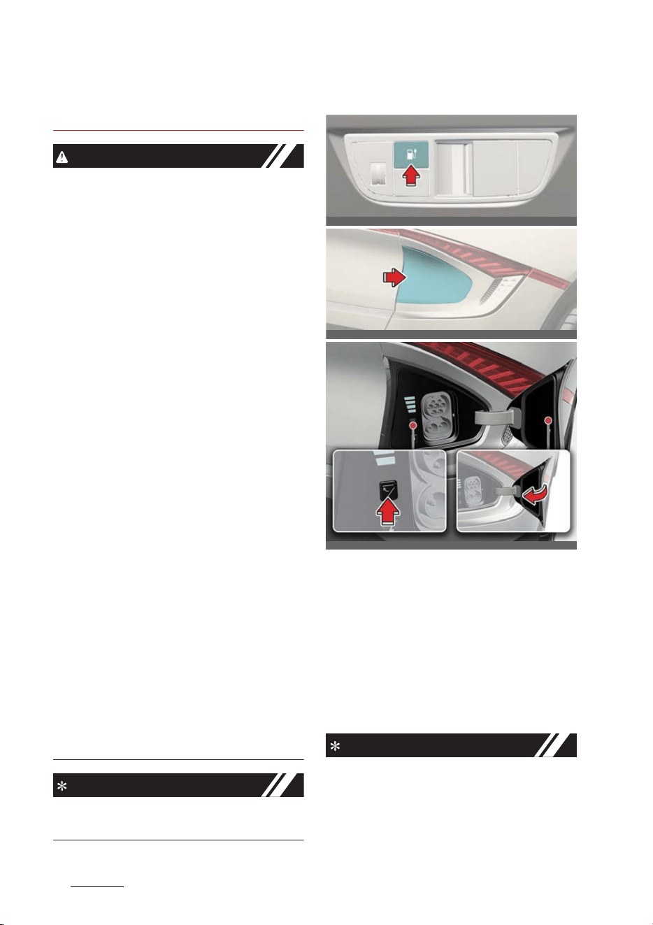
Features of your vehicle
345
Charging door
hot temperatures for extended peri
-
ods.
CAUTION
僅 Do not exceed the luggage volume
capacity of the front trunk. The over
-
weighted front trunk can be severely
damaged.
僅 Do not store the fragile objects in the
front trunk.
僅 Always keep the front trunk cover
closed securely while driving. Items
inside your vehicle are moving as fast
as the vehicle. If you have to stop or
turn quickly, or if there is a crash, the
items can be damaged.
僅 Do not spray water in the front trunk.
Vehicle driving system may get dam
-
aged since the front trunk is located
at the center of motor compartment.
僅 Be careful when you store any liquid
in the front trunk. If liquid leak outside
the front trunk, it will cause a damage
to the electric devices in the motor
compartment.
僅 Do not press the front trunk cover or
place the objects on the front trunk
cover. It may be deformed or dam
-
aged.
僅 When closing the front trunk cover, be
careful not to touch objects inside the
trunk. Loaded objects or the front
trunk may be deformed or damaged
and the front trunk cover may be
opened during driving due to poor
closing, resulting in joints and dam
-
age.
NOTICE
To avoid possible theft, do not leave
valuables in the storage compartments.
Charging door
Opening/closing the charging
door
Operation
僅 Push the charging door open/close
button on the lower crashpad.
僅 Push the charging door close button
located inner part of the charging
door.
INFORMATION
僅 The charging door automatically
closes when:
- The charging connector is discon
-
nected
OCVQ011014L
OCVQ011012L
OCVQ011013L_2

35
5
5
Features of your vehicle Charging door
- The door is opened and the
charging connector is not con
-
nected for approximately 2 minutes
- The gear is not in P (Park)
僅 After replacing battery (12 volt), open
and close the charging door once to
check that the charging door auto
-
matic opening mechanism is function
-
ing properly.
* For more details, refer to "Electric
charging door" on page 2-21.
WARNING
Do not leave the vehicle with the
charging door open. An open charging
door may indicate that the vehicle door
has been unlocked and may be subject
to vehicle theft.
CAUTION
僅 The charging door opens to the right.
Check the surrounding while the
charging door is open or close. Be
aware of your head or limbs from
being hit or stuck to the charging
door.
僅 Do not hold the hinge to prevent dam
-
aging the charging door and causing
other accidents.
NOTICE
僅If the charging door does not open
because ice has formed around it, tap
lightly or push on the door to break
the ice and release the door. If neces
-
sary, use hand temperature to melt
down the ice or move the vehicle to a
warm place and allow the ice to melt.
Do not pry on the charging door or
use unauthorized tools to open the
charging door.
僅 After closing the charging door, push
the door again to ensure that the
charging door is completely closed.
僅 Make sure that the charging door is
closed before driving the vehicle. If
the charging door is opened, mechan
-
ical parts of the charging door can be
damaged.
僅 After closed the charging door, be
sure to check the warning light is off.
僅 After charging the vehicle, close the
charging inlet by the charging inlet
cover properly. If the charging inlet
cover is closed improperly, the
charging inlet and the charging door
can be damaged.
僅 Do not pry on the charging door while
the charging door is opening. The
charging door may stop moving. Also,
the electrical mechanism of the
charging door and its related parts
can be severely damaged.
僅 While washing the vehicle, do not
spray a high pressure water to the
charging door directly. The high pres
-
sure can damage the charging door.
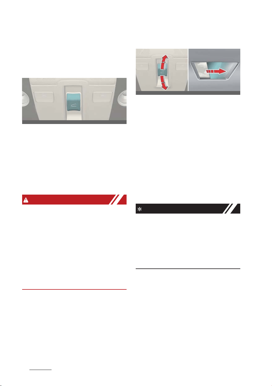
Features of your vehicle
365
Wide sunroof
Wide sunroof (if equipped)
If your vehicle is equipped with a sun
-
roof, you can slide or tilt your sunroof
with the sunroof switch located on the
overhead console.
The sunroof can only be operated when
the EV button is in the ON or START
position.
The sunroof can be operated for
approximately 3 minutes after the EV
button is in the ACC or OFF position.
However, if the front door is open, the
sunroof cannot be operated even within
the 3 minutes period.
WARNING
僅 Never adjust the sunroof or sunshade
while driving. This could result in loss
of control and an accident that may
cause injury, or property damage.
僅 Do not leave the vehicle running and
the key in your vehicle with unsuper
-
vised children. Unattended children
could operate the sunroof, which
could result in serious injury.
僅 Do not sit on the top of the vehicle. It
may cause injury or vehicle damage.
Power sunshade
Use the power sunshade to block direct
sunlight coming through the sunroof
glass.
僅 Push the sunroof switch rearward to
the first detent position, the power
sunshade automatically slides open.
僅 Push the sunroof switch forward to
the first detent position, the power
sunshade automatically closes. How
-
ever, if the sunroof glass is open, the
glass will close first.
To stop the power sunshade at any
point, push the sunroof switch in any
direction.
NOTICE
Do not pull or push the power sunshade
by hand as such action may damage the
power sunshade or cause it to malfunc
-
tion.
Wrinkles formed on the power sunshade
are normal due to material characteris
-
tic.
OCV041027L
OCV041028L_2
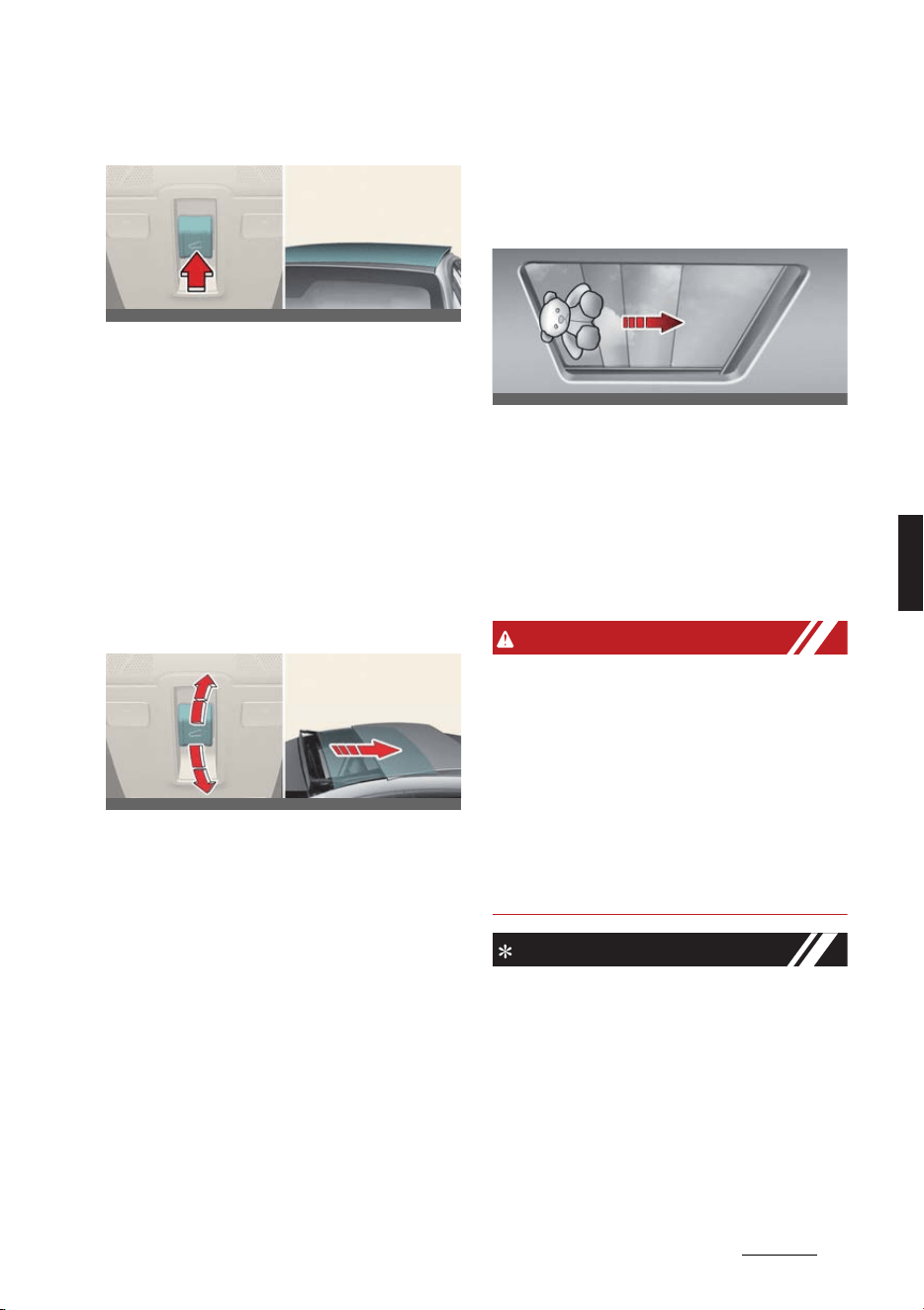
37
5
5
Features of your vehicle Wide sunroof
Tilt open/close
僅 Push the sunroof switch upward, the
sunroof glass tilts open. However, if
the power sunshade is close, the sun
-
shade will open first.
僅 Push the sunroof switch upward or
forward when the sunroof glass is tilt
opened, the sunroof glass automati
-
cally closes.
To stop the sunroof movement at any
point, push the sunroof switch in any
direction.
Slide open/close
僅 Push the sunroof switch rearward to
the first detent position, the sunroof
glass opens. However, if the power
sunshade is close, the power sun
-
shade will open first.
Push the sunroof switch forward to
the first detent position, the sunroof
glass closes. However, if the sunroof
glass is close, the power sunshade will
close.
僅 Push the sunroof switch forward or
rearward to the second detent posi
-
tion, the sunroof glass and power sun
-
shade operate automatically until full
open or full close.
To stop the sunroof movement at any
point, push the sunroof switch in any
direction.
Automatic reversal
If the power sunshade or sunroof glass
senses any obstacle while it is closing
automatically, it will reverse direction
then stop at a certain position.
The auto reverse function may not work
if an object thin or soft is caught
between the sliding power sunshade or
sunroof glass and sunroof sash.
WARNING
僅 Make sure heads, hands, arms or any
other body parts or objects are out of
the way before operating the sunroof.
Body parts or objects may get caught
causing injuries or vehicle damage.
僅 Never deliberately use your body
parts to test the automatic reversal
function. The power sunshade or sun
-
roof glass may reverse direction, but
there is a risk of injury.
NOTICE
僅 Do not continue to push the sunroof
switch after the sunroof is fully
opened, closed, or tilted. Damage to
the sunroof motor could occur.
僅 Continuous operations such as slide
open/close, tilt open/close, etc. may
cause the motor or sunroof system to
malfunction.
OCV041029L_2
OCV041030L_2
OCV041031L
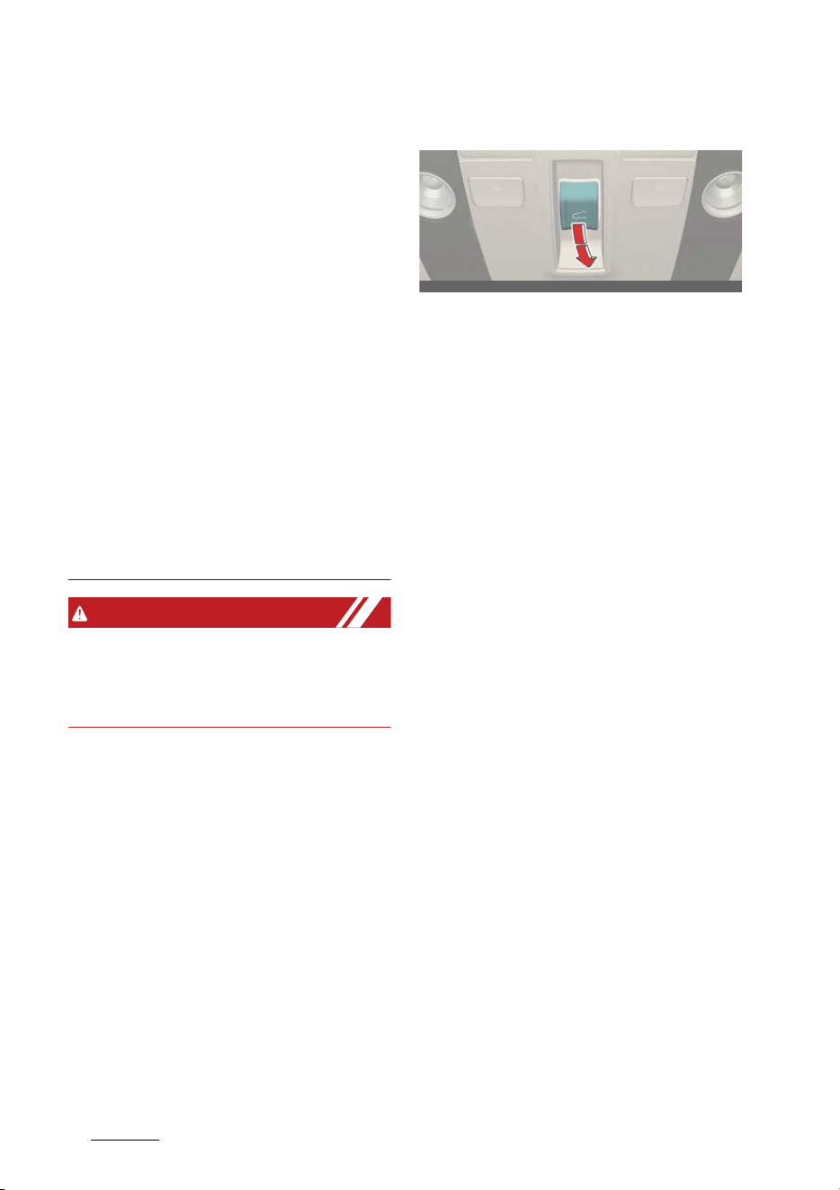
Features of your vehicle
385
Wide sunroof
僅 Regularly remove any accumulated
dust on the sunroof rail.
僅 Dust accumulated between the sun
-
roof and roof panel can make noise.
Open the sunroof and remove dust
regularly using a clean cloth.
僅 Do not try to open the sunroof when
the temperature is below freezing or
when the sunroof is covered with
snow or ice. The sunroof may not
work properly and may break if
opened by force.
僅 Do not open or drive with the sunroof
glass open immediately after rain or
washing the vehicle. Water may wet
the interior of the vehicle.
僅 Do not extend any luggage outside
the sunroof while driving. Vehicle
damage may occur if the vehicle sud
-
denly stops.
WARNING
Do not extend your head, arms, body
parts or objects outside the sunroof
while driving. Injuries may occur if the
vehicle suddenly stops.
Resetting the sunroof
In some circumstances resetting the
sunroof operation may need to be per
-
formed. Some instances where resetting
the sunroof may be required include:
僅 When the 12-volt battery is either dis
-
connected or discharged
僅 When the sunroof fuse is replaced
僅 If the sunroof one-touch AUTO OPEN/
CLOSE operation is not functioning
properly
Sunroof resetting procedure:
1. It is recommended to perform the
reset procedure with the vehicle in the
ready mode. Start the vehicle in P
(Park).
2. Make sure the power sunshade and
sunroof glass are in the fully closed
position. If the power sunshade and
sunroof glass are open, push the
switch forward until the power sun
-
shade and sunroof glass are fully
closed.
3. Release the switch when the power
sunshade and sunroof glass are fully
closed.
4. Push the switch forward until the
power sunshade and sunroof glass
move slightly. Then release the switch.
5. Once again push and hold the sun
-
roof switch forward until the power
sunshade and sunroof glass slide
open and close. Do not release the
switch until the operation is com
-
pleted.
OCV041032L
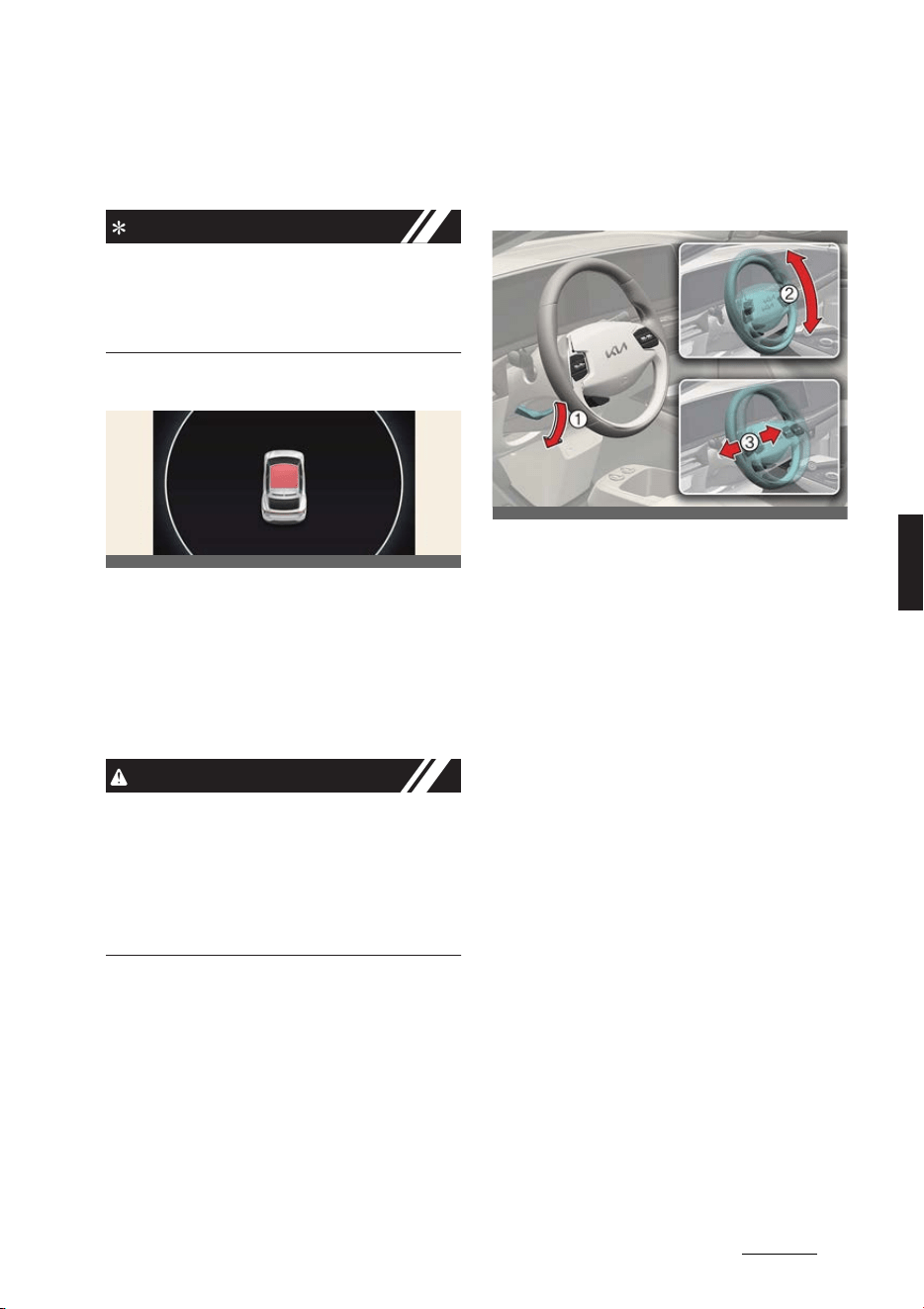
39
5
5
Features of your vehicle Steering wheel
If you release the switch during oper
-
ation, start the procedure again from
step 2.
NOTICE
If the sunroof does not reset when the
vehicle battery is disconnected or dis
-
charged, or the sunroof fuse is blown,
the sunroof may not operate normally.
Sunroof open warning
If the driver turns off the vehicle when
the sunroof is not fully closed, the warn
-
ing chime will sound for several seconds
and the sunroof open warning will
appear on the cluster LCD display.
Close the sunroof securely when leaving
your vehicle.
CAUTION
Make sure the sunroof is closed fully
when leaving your vehicle.
If the sunroof is left open, rain or snow
may wet the interior of the vehicle. Also,
leaving the sunroof open when the vehi
-
cle is unattended may invite theft.
Steering wheel
Adjusting the steering wheel
angle and height
Operation
1. Pull the lock-release lever (1) down.
2. Adjust the steering wheel to the
desired angle (2) and height (3).
3. Pull the lock-release lever up.
Heated steering wheel (if
equipped)
OCV051190L
OCV041033L_2
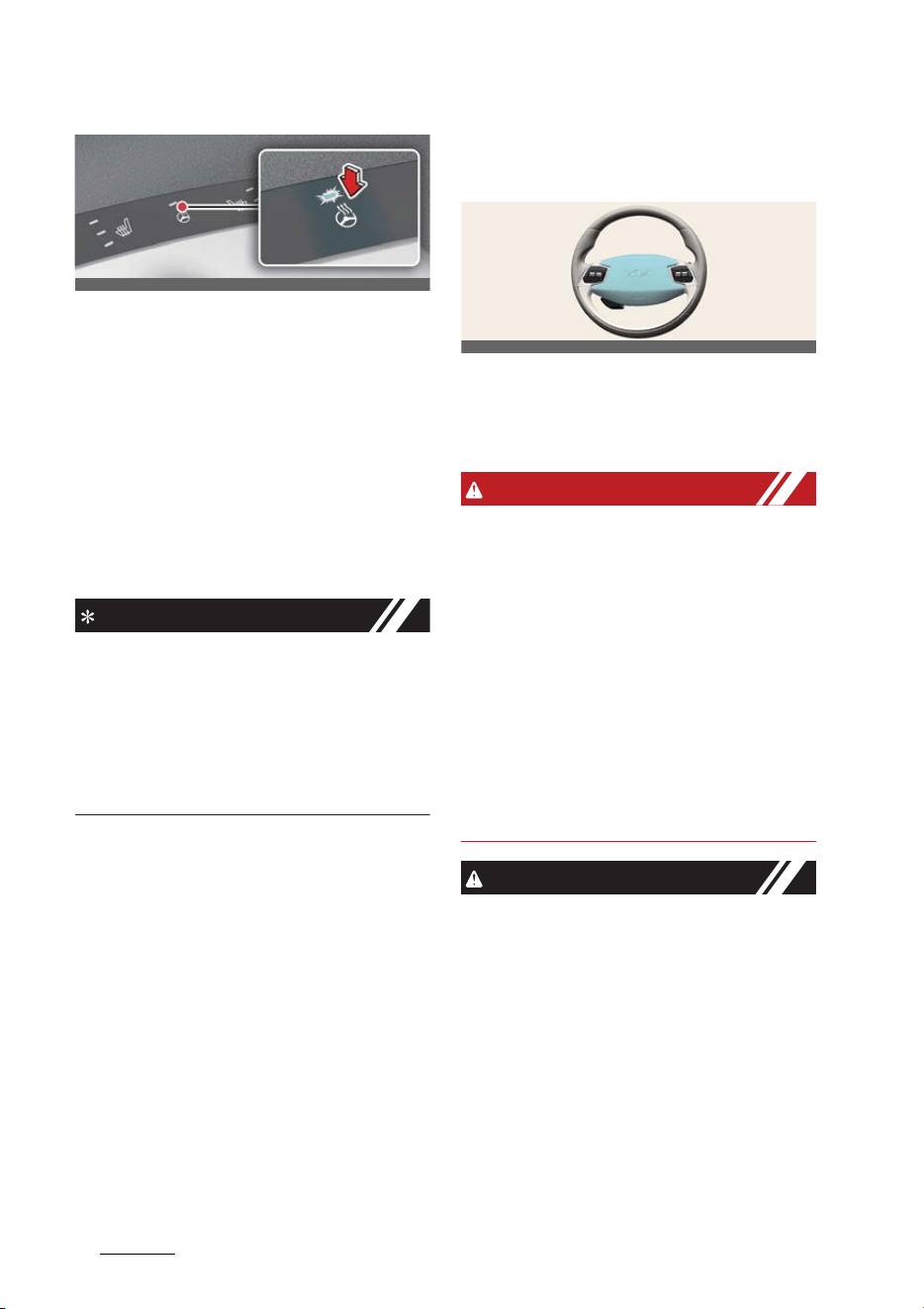
Features of your vehicle
405
Steering wheel
Operation
僅 Press the button to turn the heated
steering wheel ON or OFF.
僅 The heated steering wheel reverts to
the OFF position whenever the vehicle
is restarted.
Operating condition(s)
僅 The vehicle should be in the ON posi
-
tion.
INFORMATION
The heated steering wheel automatically
controls the steering wheel temperature
depending on the ambient temperature
when the vehicle is running. For more
details, refer to "Auto. controls that use
climate control settings (if equipped)" on
page 5-84.
Horn
Operating the horn
Operation
僅 Press the area around the horn sym
-
bol on your steering wheel.
WARNING
僅 Never adjust the angle and height of
the steering wheel while driving. You
may lose steering control and cause
severe personal injury, death or acci
-
dents.
僅 After adjusting, push the steering
wheel both up and down to be certain
it is locked in position.
僅 If the steering wheel becomes too
warm, turn the system off. The heated
steering wheel may cause burns even
at low temperatures, especially if used
for long periods of time.
CAUTION
僅 Do not install any type of grip cover
for the steering wheel, it may impair
the function of the heated steering
wheel system.
僅 When cleaning the heated steering
wheel, do not use an organic solvent
such as paint thinner, benzene, alco
-
hol and gasoline. Doing so may dam
-
age the surface of the steering wheel.
僅 If the surface of the steering wheel is
damaged by a sharp object, damage
OCV041034L
OCV041035L

41
5
5
Features of your vehicle Steering wheel
to the heated steering wheel compo
-
nents could occur.
僅Do not strike the horn severely to
operate it, or hit it with your fist. Do
not press on the horn with a sharp-
pointed object.
僅 When cleaning the steering wheel, do
not use an organic solvent such as
thinner, benzene, alcohol and gaso
-
line. Doing so may damage the steer
-
ing wheel.
NOTICE
僅 Be sure to adjust the steering wheel to
the desired position before driving.
僅 After adjustment, sometimes the lock-
release lever may not lock the steer
-
ing wheel. It is not a malfunction. This
occurs when two gears engage. In this
case, adjust the steering wheel again
and then lock the steering wheel.
僅 The following symptoms may occur
during normal vehicle operation:
- The EPS warning light does not illu
-
minate.
- The steering effort is high immedi
-
ately after pressing the EV button
to ON position. This happens as the
EPS system performs the diagnos
-
tics. When the diagnostics is com
-
pleted, the steering effort will
return to its normal condition.
- A click noise may be heard from the
EPS relay after EV button is in ON
position.
- Motor noise may be heard when
the vehicle is at a stop or at a low
driving speed.
- When the abnormality is detected
in the electric power steering sys
-
tem, a deadly accident prevention
purposes, steering assist functions
will be stopped. At this time, the
instrument cluster warning light
turns on or blinks and the power to
manipulate the steering will be off.
Please check immediately after
moving the vehicle to a safe zone.
- The steering effort increases if the
steering wheel is rotated continu
-
ously when the vehicle is not in
motion. However, after a few min
-
utes, it will return to its normal con
-
ditions.
- If the Electric Power Steering Sys
-
tem does not operate normally, the
warning light will illuminate or blink
on the instrument cluster. The
steering wheel may become diffi
-
cult to control or operate abnor
-
mally. In this case, have the system
inspected by a professional work
-
shop. Kia recommends visiting an
authorized Kia dealer/service part
-
ner.
- When you operate the steering
wheel in low temperature, abnor
-
mal noise could occur. If tempera
-
ture rises, the noise will disappear.
This is a normal condition.
- When jump starting the vehicle
after battery discharge, the steer
-
ing wheel may not function prop
-
erly. It is a temporary situation due
to low battery voltage, and upon
stable battery charging, the steer
-
ing wheel will function normally
again. Please move the steering
wheel around to make sure the
steering wheel is functioning prop
-
erly before driving the vehicle.
僅 The heated steering wheel will turn off
automatically approximately 30 min
-
utes after the heated steering wheel is
turned on.
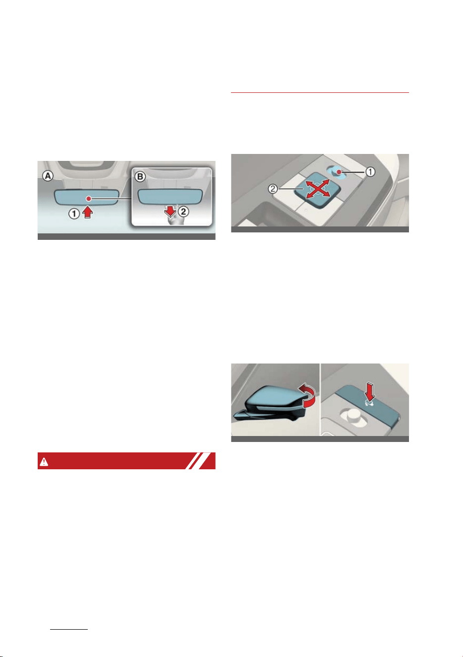
Features of your vehicle
425
Mirrors
Mirrors
Interior rearview mirror
* Make the adjustment before you start
driving.
Adjusting the day/night rearview
mirror (if equipped)
A: Day
B: Night
Operation
僅 Push the day/night lever (1) during
daytime.
僅 Pull the day/night lever (2) to reduce
headlamp glare during low light and
nighttime driving conditions.
Electric Chromic Mirror (ECM) (if
equipped)
The sensor detects the light level and
automatically controls the headlamp
glare during low light and nighttime driv
-
ing conditions.
WARNING
僅 Do not place objects in the rear seat
or cargo area which would interfere
with your vision out the rear window.
僅 Do not adjust the rear view mirror
while the vehicle is moving. This could
result in loss of control, and an acci
-
dent which could cause DEATH, SERI
-
OUS INJURY, or property damage.
僅 Do not modify the inside mirror and
don't install a wide mirror. It could
result in injury, during an accident or
deployment of the air bag.
Outside rear view mirror
Adjusting the outside rear view
mirror
Operation
1. Move the outside rear view mirror
switch (1) to select the left or right side
of the mirror.
2. Adjust the mirror adjustment control
(2) to move the selected mirror.
Folding the outside rear view mir
-
ror
Operation
僅 Press the button to fold or unfold the
mirror.
OCV041036L
OCV041037L
OCV041038L_2
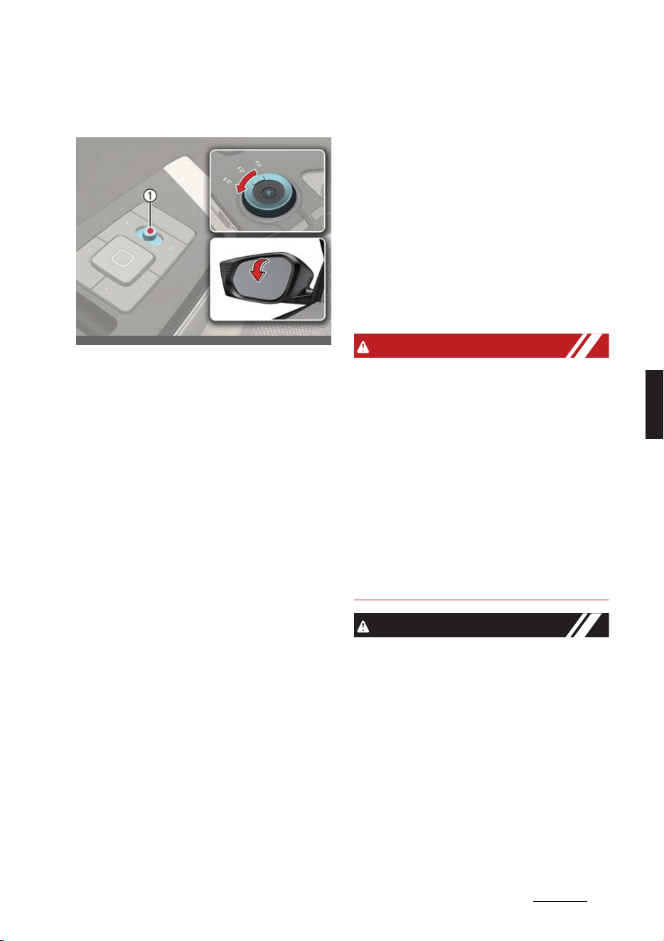
43
5
5
Features of your vehicle Mirrors
Auto reverse function (if
equipped)
The outside rear view mirror will move
downwards when the vehicle is in R
(Reverse) position to assist reverse park
-
ing.
Operation
僅 The outside rear view mirror switch (1)
position determines the mirror move
-
ment:
- L/R: Outside rear view mirrors will
move.
- Center: Outside rear view mirrors
will not move.
Auto Reverse function user set
-
ting
Operation
1. Shift to P (Park).
2. Move the switch to the L or R position
depending on the mirror you want to
adjust.
3. Shift to R (Reverse).
4. Adjust the mirror.
Initializing the Auto Reverse
function
Operation
1. Shift to P (Park).
2. Move the switch to the L or R position
depending on the mirror you want to
adjust.
3. Shift to R (Reverse).
4. Adjust the mirror higher than the
standard angle.
5. Shift to another gear position.
WARNING
僅 The outside rear view mirror is con
-
vex. Objects seen in the mirror are
closer than they appear.
僅 Use your interior rear view mirror or
direct observation to determine the
actual distance of following vehicles
when changing lanes.
僅Do not adjust or fold the outside rear
view mirrors while the vehicle is mov
-
ing. This could result in loss of control,
and an accident which could cause
DEATH, SERIOUS INJURY, or property
damage.
CAUTION
僅 Do not scrape ice off the mirror face;
this may damage the surface of the
glass. If ice should restrict the move
-
ment of the mirror, do not force the
mirror for adjustment. To remove ice,
use a deicer spray, or a sponge or soft
cloth with warm water.
僅 If the mirror is jammed with ice, do not
adjust the mirror by force. Use an
approved spray de-icer (not cooling
system antifreeze) to release the fro
-
zen mechanism or move the vehicle
OCV041039L_2

Features of your vehicle
445
Mirrors
to a warm place and allow the ice to
melt.
僅 The mirrors stop moving when they
reach the maximum adjusting angles,
but the motor continues to operate
while the switch is pressed. Do not
press the switch longer than neces
-
sary, the motor may be damaged.
僅 Do not attempt to adjust the outside
rear view mirror by hand. Doing so
may damage the parts.
僅 The electric type outside rear view
mirror operates even though the vehi
-
cle is in the OFF position. However, to
prevent unnecessary battery dis
-
charge, do not adjust the mirrors lon
-
ger than necessary while the vehicle is
not running.
僅 In case it is an electric type outside
rear view mirror, don't fold it by hand.
It could cause motor failure.
僅 We recommend following the proce
-
dures in an orderly manner to change
or initialize the auto reversing user
settings. If you move to the next step
before completing the previous one,
the changed angle may not be
changed or initialization may not work
properly.
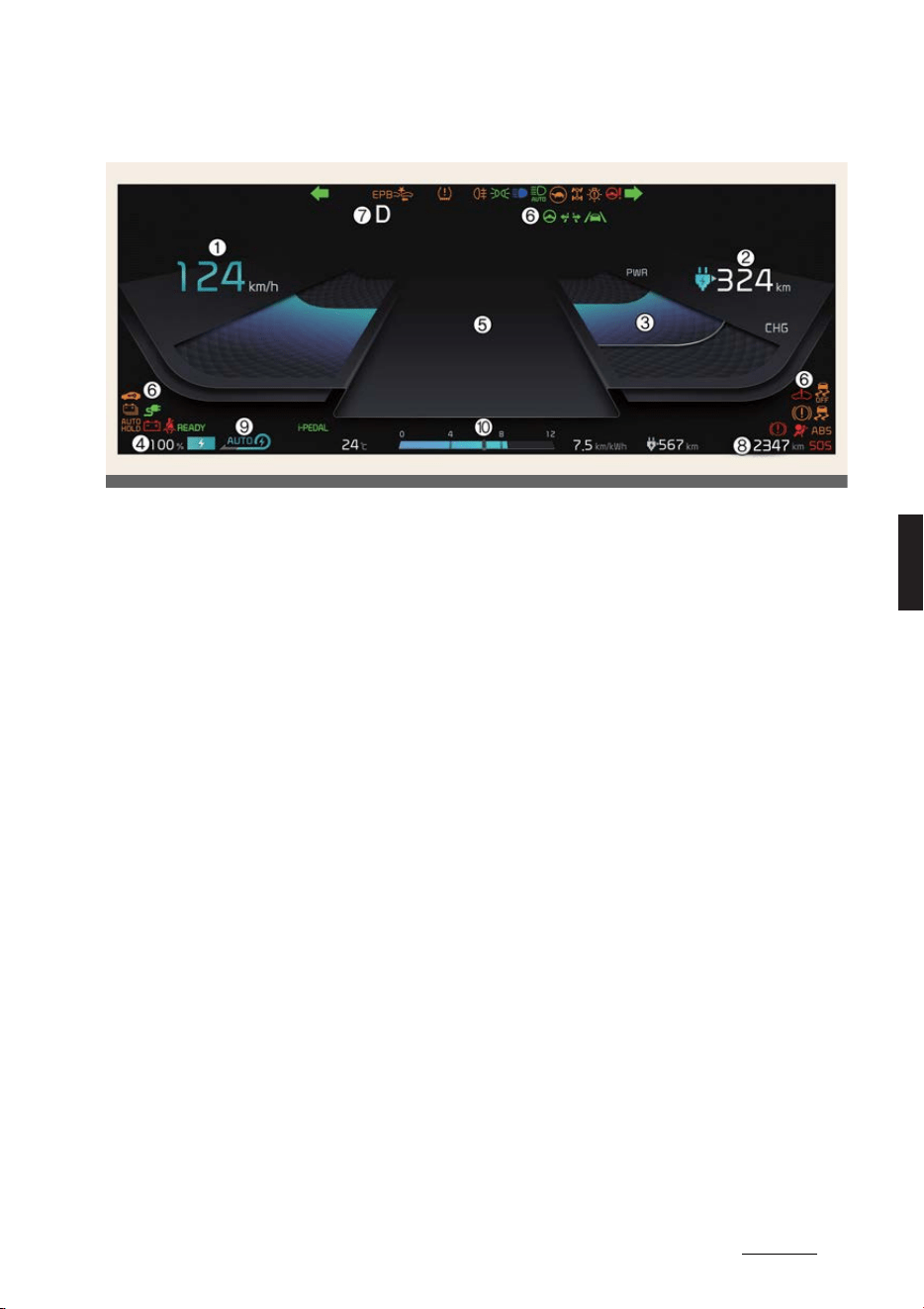
45
5
5
Features of your vehicle Instrument cluster
Instrument cluster
1. Speedometer
僅MPH, km/h
僅 The speed of the vehicle in kilometers
per hour (km/h) or miles per hour
(mph).
2. Distance to empty
僅 Estimated distance the vehicle can be
driven with the remaining electric
energy.
3. Power/Charge gauge
僅 The energy consumption rate of the
vehicle and the charge/discharge sta
-
tus of the regenerative brakes.
4. Battery SOC (State of Charge)
gauge
僅 Charging status of the high voltage
battery.
5. LCD display
僅 Refer to "LCD display" on page 5-47.
6. Warning and indicator lights
僅 Refer to "Warning and indicator lights"
on page 5-54.
7. Reduction gear shift indicator
僅 The indicator displays which gear is
selected.
8. Odometer
僅 The odometer indicates the total dis
-
tance that the vehicle has been
driven.
9. Regenerative braking level
indicator
僅 Refer to "Regenerative braking sys
-
tem" on page 6-15.
10. Electric energy economy
僅 Refer to "Trip computer mode" on
page 5-48.
OCV041155L
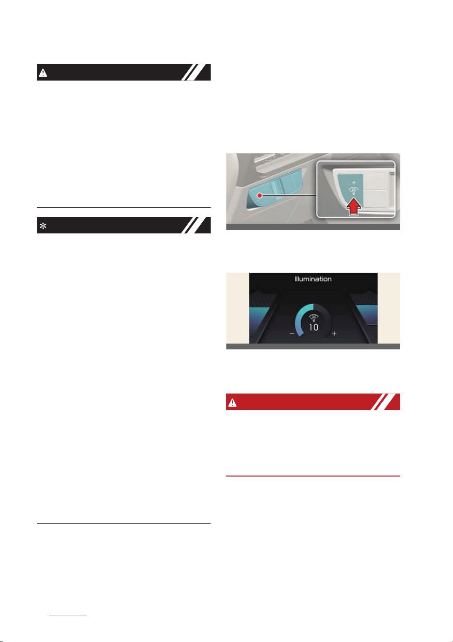
Features of your vehicle
465
Instrument cluster
CAUTION
僅 The information is displayed after get
-
ting information from a weather infor
-
mation provider via GPS. Depending
on conditions of GPS reception, the
information may be different from the
current weather in your area.
僅 Be careful while driving as dynamic-
themed animation effects can distract
the driver and lead to unexpected
accidents.
NOTICE
僅 When the remaining battery is lower
than 10% for the high voltage battery,
the vehicle speed is limited and then
eventually the vehicle will turn OFF.
Charge the vehicle immediately.
僅 If the vehicle is not on level ground or
the battery power has been inter
-
rupted, the distance to empty function
may not operate correctly.
僅 The distance to empty may differ
from the actual driving distance as it
is an estimate of the available driving
distance.
僅 The distance to empty may vary sig
-
nificantly based on driving condi
-
tions, driving habits, and condition of
the vehicle.
僅 Use a clean soft microfiber cloth to
gently wipe any finger prints off the
touch screen.
僅 The instrument cluster for the right-
hand drive vehicle may be on the
opposite side show differently.
Instrument panel illumination
control (if equipped)
The brightness of the instrument panel
illumination is changed by pressing the
illumination control button ("+" or "-")
when the vehicle's position lights or
headlamps are turned on.
僅 If you hold the illumination control
button ("+" or "-"), the brightness will
be changed continuously.
僅 If the brightness reaches to the maxi
-
mum or minimum level, an alarm will
sound.
WARNING
Never adjust the instrument cluster
while driving. This could result in loss of
control and lead to an accident that may
cause death, serious injury, or vehicle
damage.
OCV041057N
OCV041611N
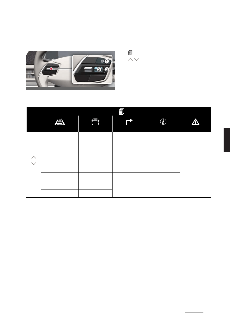
47
5
5
Features of your vehicle LCD display
LCD display
Changing LCD display modes
1
: MODE button for changing modes
2
/ : MOVE switch for changing
items
3
OK: SELECT/RESET button for setting
or resetting the selected item
LCD display modes
OCV041040L
Mode
Driving Assist Trip Computer Turn By Turn (TBT)* Information Master Warning
Up/
Down
Forward Collision-Avoid
-
ance Assist
Lane Keeping Assist
Blind-Spot Collision-
Avoidance Assist
Smart Cruise Control
Lane Following Assist
Highway Driving Assist
Drive Information Route Guidance TPMS
The Master Warn
-
ing mode displays
warning messages
related to the vehicle
when one or more
systems is not oper
-
ating normally.
Driver Attention Warning After Recharging Destination Info
Intelligent Speed Limit
Assist
Accumulated Info
Energy Flow (4WD)
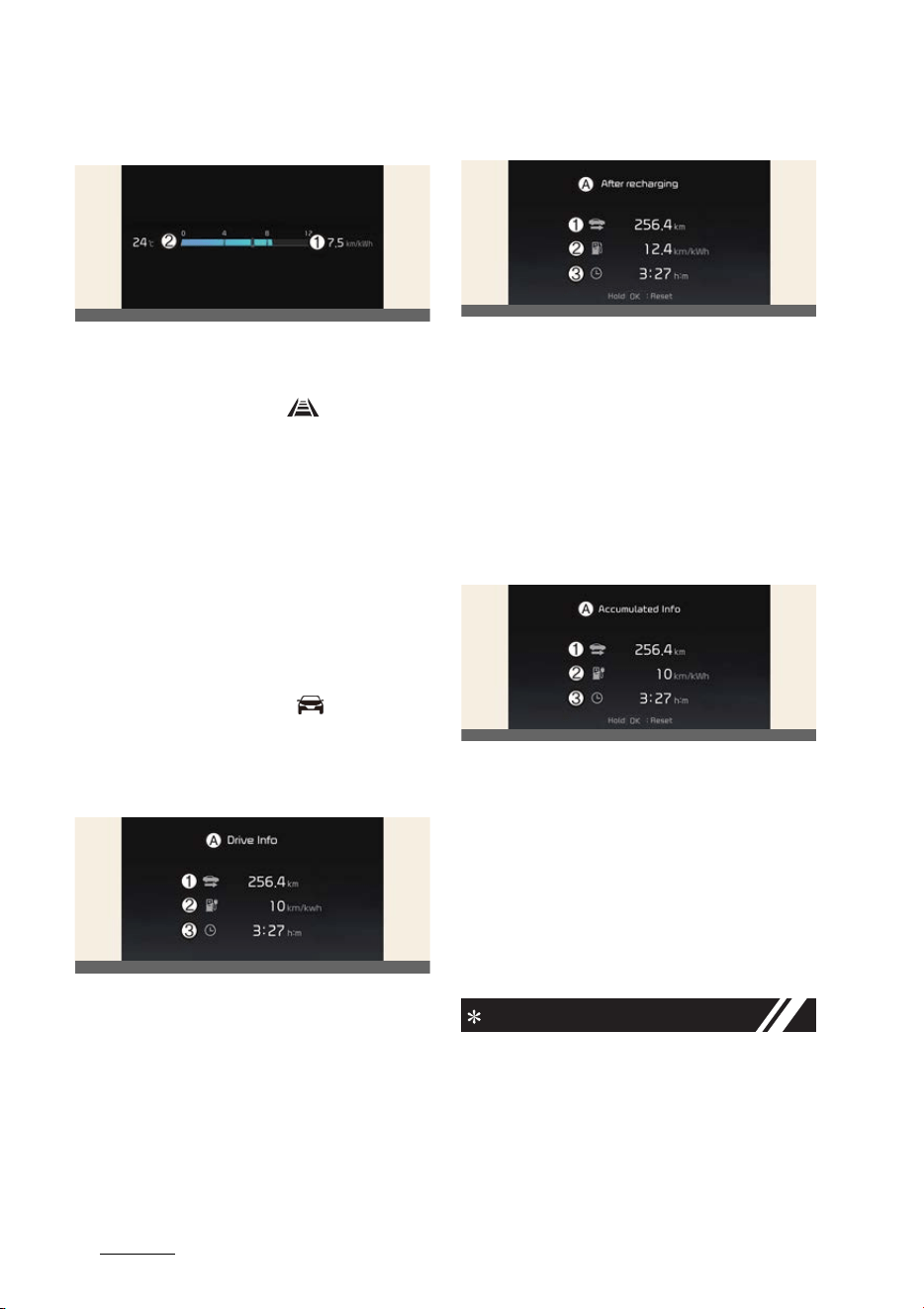
Features of your vehicle
485
LCD display
Electric energy economy
1
Average electric energy economy
2
Instant electric energy economy
Driving assist mode
This mode displays the state of:
僅 Forward Collision-Avoidance Assist
Lane Keeping Assist
Blind-Spot Collision-Avoidance Assist
Smart Cruise Control
Lane Following Assist
Highway Driving Assist
僅 Driver Attention Warning
僅 Intelligent Speed Limit Assist
Trip computer mode
* You may change through items in the
following order.
Drive Info
A:
Drive Info
1
Accumulated trip distance
2
Average energy consumption
3
Total driving time
The driver's door is opened after turning
off the vehicle or the vehicle is turned on
after 3 minutes have passed, the Drive
Info screen will reset.
After recharging
A:
After recharging
1
Accumulated trip distance
2
Average energy consumption
3
Total driving time
The information after recharging.
To manually reset the information, press
and hold the OK button when viewing
the
After recharging
.
Accumulated Info
A:
Accumulated Info
1
Accumulated trip distance
2
Average energy consumption
3
Total driving time
The information is accumulated starting
from the last reset.
To manually reset the information, press
and hold the OK button when viewing
the
Accumulated Info
.
NOTICE
僅 The vehicle must be driven for a mini
-
mum of 300 meters (0.19 miles) since
the last cycle before the accumulated
driving information is recalculated.
僅 The average electric energy economy
is not displayed for more accurate cal
-
culation if the vehicle does not drive
OCV041121L
OCV041123L
OCV041415L
OCV041122L
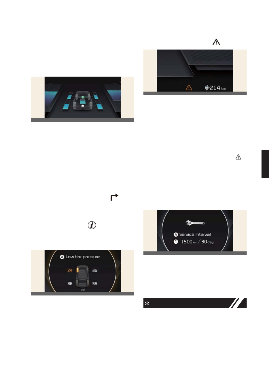
49
5
5
Features of your vehicle LCD display
more than 10 seconds or 50 meters
(0.03 miles) since the EV button is
turned to ON.
Energy flow (4WD) (if equipped)
僅 The electric vehicle system informs
the drivers its energy flow in various
operating modes.
僅 The distribution status of the driving
power of the front and rear wheels
are displayed when Auto 4WD mode
is activated. For more details, refer to
"All wheel drive (4WD) (if equipped)"
on page 6-39.
Turn By Turn (TBT) mode
This mode displays the Navigation sta
-
tus.
Information mode
Tire pressure
A:
Low tire pressure
僅 Information related to Tire Pressure.
Refer to "Tire Pressure Monitoring
System (TPMS)" on page 7-6.
Master warning mode
This mode informs you of the following
situations:
僅 Driver assistance system malfunction,
limitation or radar/camera blockage
僅 LED headlamp malfunction
僅 Lamp malfunction
僅 TPMS failure, low tire pressure, etc.
At this time, a Master Warning icon ( )
will appear in the lower right corner on
the LCD display. If the warning situation
is solved, the master warning light will
be turned off and the Master Warning
icon will disappear.
Service Interval
A:
Service Interval
1
Service interval schedule
To reset the service interval, select
Set
-
tings
→
Vehicle
→
Cluster
→
Service
Interval
→
Reset
.
NOTICE
Calculates and displays when you need
a scheduled maintenance service (mile
-
age or days). If the remaining mileage or
time reaches 1,500 km (900 miles) or 30
days, the message
Service in
is dis
-
OCV041417L
OCV041126L
OCV041416L
OCV041124L

Features of your vehicle
505
LCD display
played for several seconds each time
you set the vehicle to the ON position.
Driver assistance settings (info
-
tainment system)
select
Settings
→
Vehicle
→
Driver
assistance
on the infotainment system
screen to set the Driver Assistance func
-
tion.
僅
Driver assistance
-
SCC (Smart Cruise Control)
-
Driving Convenience
-
Speed limit
-
Warning timing
-
Warning volume
-
Haptic warning
-
DAW (Driver Attention Warning)
-
Forward safety
-
Lane safety
-
Blind-spot safety
-
Parking safety
OCV041584L
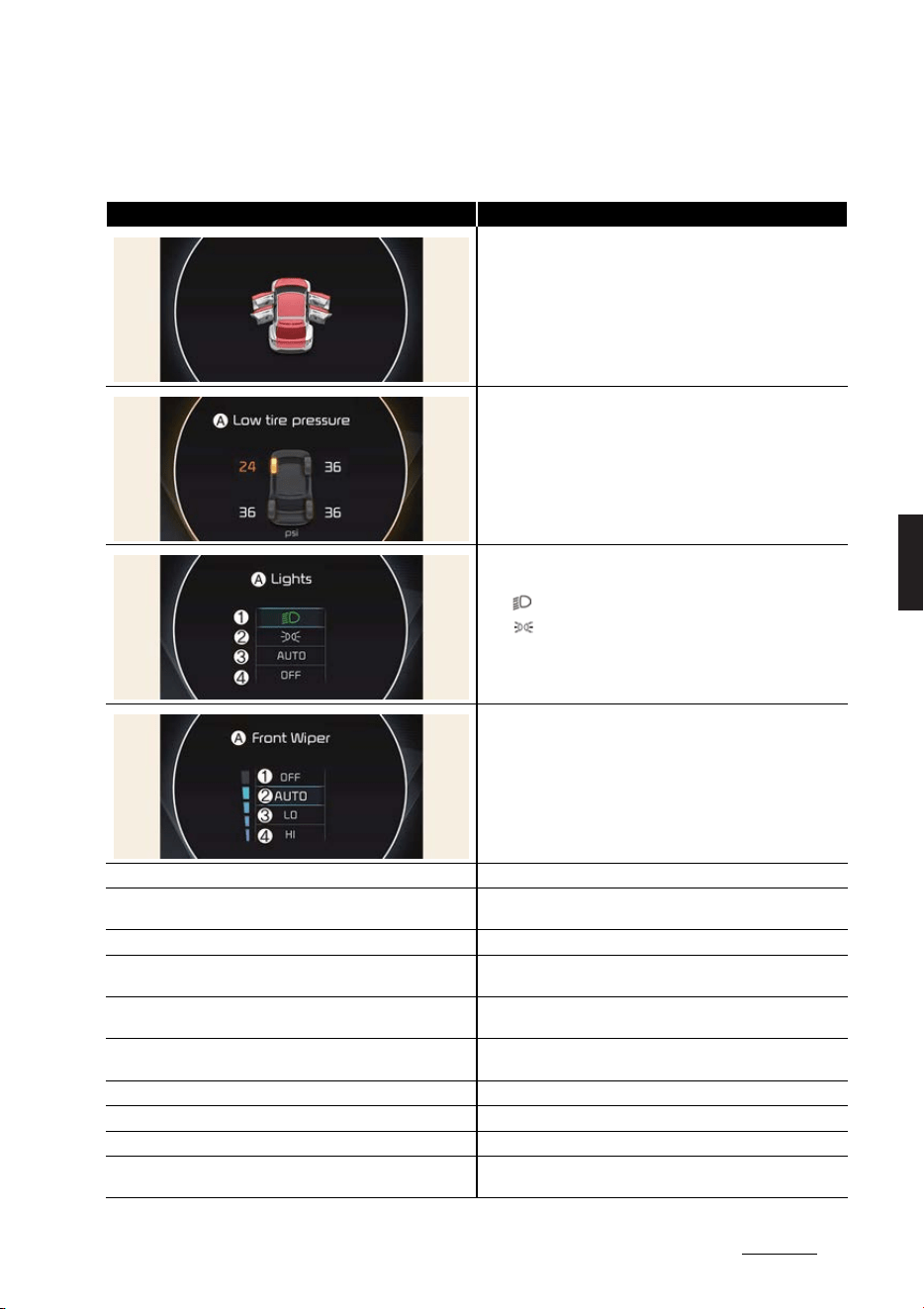
51
5
5
Features of your vehicle LCD display
LCD display messages
* For EV warning messages, refer to "LCD display messages" on page 2-41.
LCD displays Displayed contents
Door, hood, tailgate, sunroof open
Low tire pressure warning display
A:
Low tire pressure
僅A:
Lights
僅1:
僅2:
僅3: AUTO
僅4: OFF (O)
僅A:
Front Wiper
僅 1: OFF (O)
僅2: AUTO
僅3: LO (1)
僅4: HI (2)
Low washer fluid
The washer fluid level in the reservoir is nearly empty
Icy road warning
The temperature on the outside temperature gauge is below
approximately 4 °C (40 °F).
Low key battery
The battery in the smart key is flat
Press START button while turning wheel
The steering wheel does not unlock normally when the EV button
is pressed
Steering wheel unlocked
The steering wheel does not lock when the EV button changes to
the OFF position
Check steering wheel lock system
The steering wheel does not lock normally when the EV button
changes to the OFF position
Check haptic steering wheel system
There is a problem with the haptic steering wheel system
Key not in vehicle
The smart key is not in the vehicle when you press the EV button
Key not detected
The smart key is not detected when you press the EV button
Press start button again
The EV button cannot be operated due to a problem with the EV
button system

Features of your vehicle
525
LCD display
INFORMATION
僅 If there is no problem with the opera
-
tion and the messages above are con
-
stantly displayed, have your vehicle
inspected by a professional workshop.
Kia recommends to contact an autho
-
rized Kia dealer/service partner.
僅 Press start button again
- You could start the vehicle by
pressing the EV button once more.
- If the warning message is displayed
each time you press the EV button,
have the vehicle inspected by a
professional workshop. Kia recom
-
mends visiting an authorized Kia
dealer/service partner.
僅 Check BRAKE SWITCH fuse
- You need to replace the fuse with a
new one before starting the vehicle.
- If that is not possible, you can start
the vehicle by pressing the EV but
-
ton for 10 seconds in the ACC posi
-
tion.
NOTICE
僅 Some driving information stored in
the trip computer resets if the battery
is disconnected.
僅 If any of the following conditions
occurs, the mileage and days may be
incorrect.
- The battery cable is disconnected.
- The battery is discharged.
僅 If sunroof open warning is displayed
in the cluster, the Driving Information
message may not be displayed.
僅 To set the charging time and/or cli
-
mate time, refer to Navigation Quick
Reference Guide.
僅 If the icy road warning appears while
driving, you should drive more atten
-
tively and safely refraining from over-
speeding, rapid acceleration, sudden
braking or sharp turning, etc.
Press start button with key
The EV button is pressed while the "Key not detected" warning
message is displayed
Check Blind-Spot Safety system
Problem with Blind-Spot Collision-Avoidance Assist
Check BRAKE SWITCH fuse
The brake switch fuse is disconnected
Refill coolant
The coolant is low
LCD displays Displayed contents

53
5
5
Features of your vehicle Vehicle settings (infotainment system)
Vehicle settings (infotainment
system)
1. Press the
Settings
button on the head
unit of the infotainment system.
2. Select
Vehicle
and change the setting
of the features.
Vehicle Settings in the infotainment sys
-
tem provides user options for a variety
of settings including door lock/unlock
features, convenience features, driver
assistance settings, etc.
僅
Vehicle settings
-
Driver assistance
-
Drive mode
-
ECO Vehicle
-
Active sound design
-
Head-up display
-
Cluster
-
Climate
-
Seat
-
Lights
-
Door
-
Convenience
WARNING
Do not operate the
Vehicle settings
while driving. This may cause distraction
resulting in an accident.
NOTICE
僅 The information provided may differ
depending on which features are
applicable to your vehicle.
僅 For detailed information, refer to Nav
-
igation Quick Reference Guide.
OCV041584L
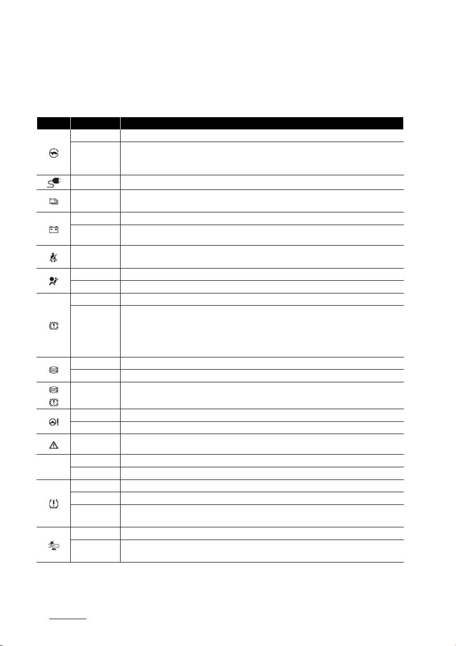
Features of your vehicle
545
Warning and indicator lights
Warning and indicator lights
Once you set the vehicle to the ON position, the symbols shown below will light up. If these symbols remain on or malfunction, we
recommend having the vehicle inspected by an authorized Kia dealer/service partner.
The information provided may differ according to which functions are applicable to your vehicle.
Symbol Time Notes
3 seconds Power down indicator light illuminates for approximately 3 seconds.
Continuously
僅 The high voltage battery level is too low or voltage is decreasing
僅 The temperature of the high voltage battery is too high or too low
僅 The temperature of the motor is high
Continuously Charging indicator light illuminates when charging the high voltage battery.
Continuously
High voltage battery level warning light illuminates when the high voltage battery level is low.
When the warning light turns ON, charge the battery immediately.
3 seconds Charging system warning light illuminates for approximately 3 seconds and then goes off.
Continuously
僅 Whenever there is a malfunction with either the LDC (Low DC-DC converter) or electrical charging
system.
Continuously
Seat belt warning light informs the driver that the seat belt is not fastened.
Refer to "Seat belts" on page 4-13.
6 seconds The air bag warning light illuminates for about 6 seconds and then turns off.
Continuously 僅 There is a malfunction with the Safety Restraint System (SRS) air bag operation.
3 seconds Parking brake & brake fluid warning light illuminates for approximately 3 seconds.
Continuously
僅 Red: When the parking brake is applied.
僅 Red: When the brake fluid level in the reservoir is low.
僅 Red: When the regenerative brake does not operate.
僅 Yellow: Regenerative brake warning light illuminates when the regenerative brake does not oper
-
ate and the brake does not perform well.
3 seconds The ABS warning light illuminates for about 3 seconds and then goes off.
Continuously 僅 Whenever there is a malfunction with the ABS.
Continuously
Electronic Brake Force Distribution (EBD) system warning light illuminates when there is a problem
with the Electronic Brake Force Distribution system.
3 seconds Electric Power Steering (EPS) warning light illuminates for about 3 seconds and then goes off.
Continuously 僅 Whenever there is a malfunction with the electric power steering.
Continuously
Master warning light illuminates when there is a malfunction in various vehicle functions. To identify
the details of the warning, refer to the LCD display warning message.
EPB
3 seconds Electronic Parking Brake
EPB
warning light illuminates for about 3 seconds and then goes off.
Continuously 僅 Whenever there is a malfunction with the Electronic Parking Brake
EPB
3 seconds Low tire pressure warning light illuminates for approximately 3 seconds and then goes off.
Continuously 僅 When one or more of your tires are significantly underinflated.
Blinking
僅 When there is a malfunction with the TPMS.
Refer to "Tire Pressure Monitoring System (TPMS)" on page 7-6.
3 seconds Forward Safety warning light illuminates for approximately 3 seconds and then goes off.
Continuously
僅 Whenever there is a malfunction with Forward Collision-Avoidance Assist.
Refer to "Forward Collision-Avoidance Assist (FCA) (if equipped)" on page 6-43.
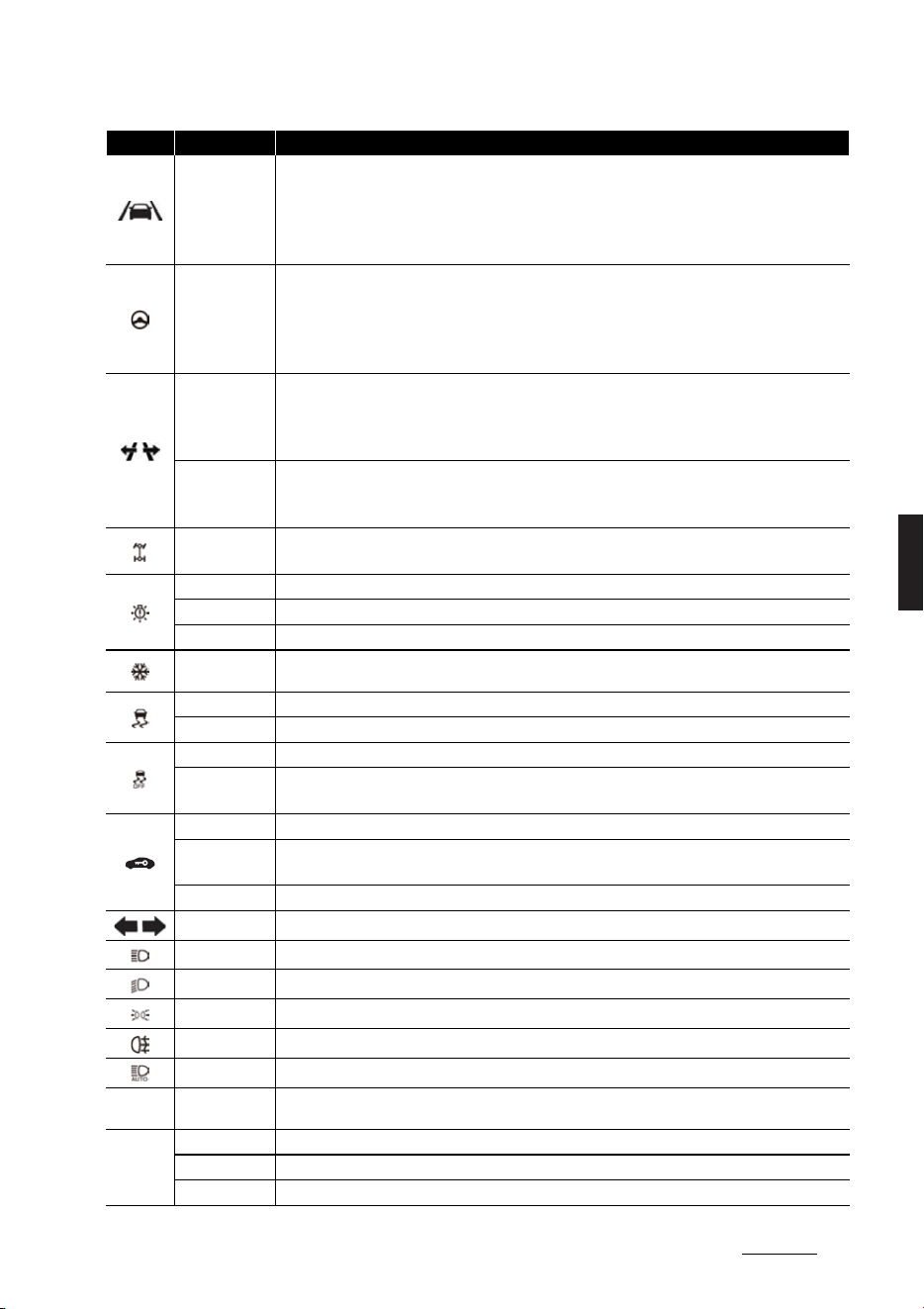
55
5
5
Features of your vehicle Warning and indicator lights
Continuously
Lane safety indicator light illuminates:
僅 Green: When Lane Keeping Assist operating conditions are satisfied.
僅 White: When Lane Keeping Assist operating conditions are not satisfied.
僅 Yellow: Whenever there is a malfunction with Lane Keeping Assist.
Refer to "Lane Keeping Assist (LKA) (if equipped)" on page 6-62.
Continuously
Lane Following Assist indicator light illuminates:
僅 Green: When Lane Following Assist is activated
僅 Gray: When Lane Following Assist operating conditions are not satisfied
僅 Yellow: Whenever there is a malfunction with Lane Following Assist
Refer to "Lane Following Assist (LFA)" on page 6-123.
Continuously
Highway Lane Change Assist indicator light illuminates:
僅 Green: When Highway Lane Change Assist is ready for operation.
僅 Grey: When Highway Lane Change Assist is in standby.
Refer to "Highway Driving Assist (HDA) (if equipped)" on page 6-126.
Blinking
僅 Green: When Highway Lane Change Assist is operating.
僅 White: When Highway Lane Change Assist is canceled.
Refer to "Highway Driving Assist (HDA) (if equipped)" on page 6-126.
Continuously
Whenever there is a malfunction with the 4WD system.
Refer to "All wheel drive (4WD) (if equipped)" on page 6-39.
3 seconds LED headlight warning light illuminates for approximately 3 seconds and then goes off.
Continuously 僅 Whenever there is a malfunction with the LED headlight.
Blinking 僅 Whenever there is a malfunction with a LED headlight related part.
Continuously
Icy road warning light and outside temperature gauge blinks and then illuminates. Also, the warning
chime sounds 1 time.
3 seconds Electronic Stability Control indicator light illuminates for about 3 seconds and then goes off.
Continuously 僅 Whenever there is a malfunction with ESC system.
3 seconds The ESC OFF indicator light illuminates for approximately 3 seconds and then goes off.
Continuously
僅 When you deactivate ESC system by pressing the ESC OFF button.
Refer to "Electronic Stability Control (ESC)" on page 6-29.
Continuously When the vehicle detects the smart key in the vehicle in ACC/ON position
Blinking
When the key is not in the vehicle
Whenever there is a malfunction with the immobilizer system.
2 seconds When the vehicle cannot detect the smart key.
Blinks When the turn signal light is on
Continuously When high-beam headlamps are on.
Continuously When low-beam headlamps are on.
Continuously When the light switch is in the ON position
Continuously When the rear fog lights are on.
Continuously When High Beam Assist or Intelligent Front-Lighting System is activated.
AUTO
HOLD
Continuously When AUTO HOLD is activated.
READY
Continuously Ready indicator illuminates when the vehicle is ready to be driven.
Off 僅 Normal driving is not possible, or a problem has occurred.
Blinking 僅 Emergency driving, there is a problem with the system.
Symbol Time Notes
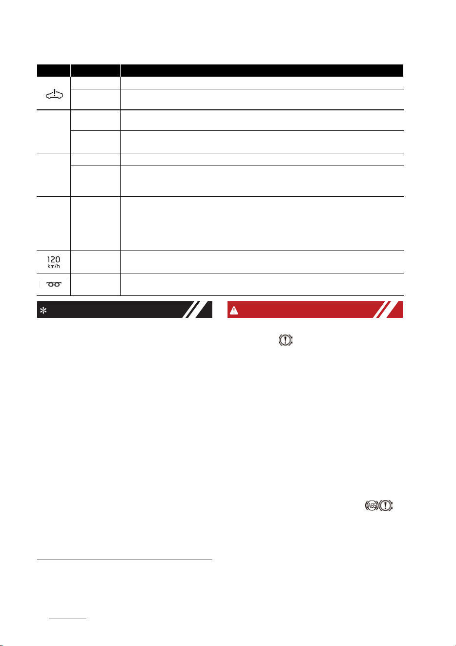
Features of your vehicle
565
Warning and indicator lights
INFORMATION
僅 Dual-diagonal braking system
Your vehicle is equipped with dual
diagonal braking systems. This means
you still have braking on two wheels
even if one of the dual systems should
fail.
With only one of the dual systems
working, more than normal pedal
travel and greater pedal pressure are
required to stop the vehicle. Also, the
vehicle will not stop in as short a dis
-
tance with only a portion of the brake
system working.
僅 Ready Indicator READY
When the ready indicator goes OFF or
blinks, there is a problem with the sys
-
tem. In this case, Kia recommend that
you have your vehicle inspected by an
authorized Kia dealer/service partner.
WARNING
僅 Parking brake & brake fluid warn
-
ing light
- Driving the vehicle with a warning
light ON is dangerous. If the park
-
ing brake & brake fluid warning
light illuminates with the parking
brake released, it indicates that the
brake fluid level is low.
- In this case, have the vehicle
inspected by a professional work
-
shop. Kia recommends visiting an
authorized Kia dealer/service part
-
ner.
僅 Electronic Brake force Distribution
(EBD) system warning light
- When both ABS and parking brake
& brake fluid warning lights are on,
the brake system will not work nor
-
mally and you may experience an
unexpected and dangerous situa
-
tion during sudden braking.
3 seconds Service warning light illuminates for approximately 3 seconds and then goes off.
Continuously
僅 When there is a problem with related parts of the electric vehicle control system, such as sensors,
etc.
AFS
3 seconds
Intelligent Front-Lighting System warning light illuminates for approximately 3 seconds and then goes
off.
Continuously
僅 Whenever there is a malfunction with Intelligent Front-Lighting System.
Refer to "Intelligent front-lighting system (IFS) (if equipped)" on page 5-65.
SOS
3 seconds SOS warning light illuminates for approximately 3 seconds and then goes off.
Continuously
僅 Whenever there is a malfunction with the eCall system.
Refer to "Pan-European eCall system (if equipped)" on page 7-18 or "ERA-GLONASS emergency call
(if equipped)" on page 7-23.
ECO
SPORT
SNOW
GT
MY
Continuously
When you select each mode as drive mode.
Refer to "Drive mode integrated control system" on page 6-35.
Blinking
Overspeed warning light blinks when you drive the vehicle more than 120 km/h.
The overspeed warning chime also sound for approximately 5 seconds.
Continuously
When Battery Conditioning Mode is activated.
Refer to "Battery conditioning mode (if equipped)" on page 2-15.
Symbol Time Notes

57
5
5
Features of your vehicle Warning and indicator lights
- In this case, avoid high speed driv
-
ing and abrupt braking. We recom
-
mend you have the vehicle
inspected by an authorized Kia
dealer/service partner as soon as
possible.
僅 Safe stopping
- The TPMS cannot alert you to
severe and sudden tire damage
caused by external factors.
- If you notice any vehicle instability,
immediately take your foot off the
accelerator pedal, apply the brakes
gradually with light force, and
slowly move to a safe position off
the road.
NOTICE
僅 Make sure that all warning lights are
OFF after starting the vehicle. If any
light is still ON, this indicates a situa
-
tion that needs attention.
僅 Power down indicator light
-Do not accelerate or start the vehi
-
cle suddenly when the power down
indicator light is ON.
When the power is limited for the
safety of the high-powered parts of
an electric vehicle, the power down
indicator light illuminates. Your
vehicle may not be driven, or may
roll back on a slope with the indica
-
tor light ON.
僅 Electronic Brake force Distribution
(EBD) system warning light
- When the ABS warning light is on or
both ABS and Parking Brake &
Brake Fluid warning lights are on,
the speedometer, odometer, or trip
-
meter may not work. Also, the EPS
warning light may illuminate and
the steering effort may increase or
decrease.
- In this case, avoid high speed driv
-
ing and abrupt braking. We recom
-
mend you have the vehicle
inspected by an authorized Kia
dealer/service partner as soon as
possible.
僅 The Electronic Parking Brake
EPB
warning light may illuminate when the
Electronic Stability Control (ESC) indi
-
cator light comes on to indicate that
the ESC is not working properly (This
does not indicate malfunction of the
EPB).
僅 Continuous driving with the LED
Headlight warning light on or blinking
can reduce LED headlight life.
僅 If the icy road warning light appears
while driving, you should drive more
attentively and safely refraining from
over-speeding, rapid acceleration,
sudden braking or sharp turning, etc.
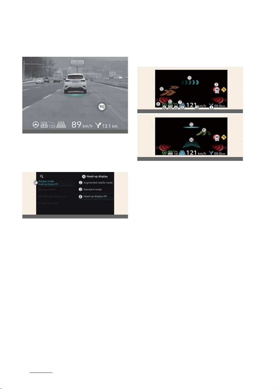
Features of your vehicle
585
Augmented Reality HUD
Augmented Reality HUD (if
equipped)
The Head-Up Display projects the instru
-
ment cluster and navigation information
onto the windshield.
Head-up display settings
A:
Head-up display
1 Display mode
2 Augmented reality mode
3 Standard mode
4 Head-up display off
Head-up display can be enabled from
the Settings menu in the infotainment
system screen. Select either
Augmented
reality mode
or
Standard mode
from:
僅
Settings
→
Vehicle
→
Head-up dis
-
play
→
Display mode
→
Augmented
reality mode
/
Standard mode
After turning on the head-up display,
you can change the settings of
Display
control
,
Augmented reality calibra
-
tion
and
Content selection
of the
Head-Up Display.
Head-up display information
AR mode display information
1
Turn By Turn (TBT) navigation infor
-
mation
2
Traffic information
3
Speedometer information
4
SCC set speed information
5
SCC vehicle distance information
6
Lane Following Assist information
7
Lane Safety information
8
Blind-Spot Safety information
9
Highway Auto Speed Change infor
-
mation
10
Highway Driving Assist information
11
Turn by turn (TBT) navigation infor
-
mation (AR)
12
Lane Safety information (AR)
13
Front Vehicle indicator (AR) (if High
-
way Lane Change Assist function
equipped)
14
Leading Vehicle Departure Alert (AR)
15
Highway Lane Change Assist infor
-
mation (AR)
OCV041418L
OCV041186L
OCV041419L
OCV041420L

59
5
5
Features of your vehicle Augmented Reality HUD
Standard mode display informa
-
tion
1
Turn By Turn (TBT) navigation infor
-
mation
2
Traffic information
3
Speedometer information
4
SCC set speed information
5
SCC vehicle distance information
6
Lane Following Assist information
7
Lane Safety information
8
Blind-Spot Safety information
9
Highway Auto Speed Change infor
-
mation
10
Highway Driving Assist information
11
Surrounding vehicle information
Precautions while using the
head-up display
僅 It may sometimes be difficult to read
information on the Head-Up Display
in the following situations.
- The driver is improperly positioned
in the driver's seat
- The driver wears polarizing-filter
sunglasses
- An object is located above the
head-up display cover
- The vehicle is driven on a wet road
- Any improper lighting accessory is
installed inside the vehicle, or there
is incoming light from outside of
the vehicle
- The driver wears glasses
- The driver wears contact lenses
僅 When it is difficult to read the Head-
Up Display information, adjust the
image position, brightness level or AR
matching information from the Set
-
tings menu in the infotainment sys
-
tem screen.
僅 The AR mode display information
may be difficult to recognize when the
vehicle is driven under severe weather
condition, such as heavy rain, heavy
snow, low visibility, etc.
僅 Head-up display information may
partially overlap the road ahead,
causing fatigue and discomfort while
driving. Adjust the image if you feel
tired or uncomfortable, or if symp
-
toms persist, turn off the head-up dis
-
play.
僅 When the direct flash light or sunlight
hits the front windshield, a warning
message will appear. If the tempera
-
ture of the front windshield keep rises,
Head-up display will be deactivated
temporarily to protect Head-up dis
-
play from the high temperature. When
the temperature drops, Head-up dis
-
play will be reactivated.
僅 For your safety, make sure to stop the
vehicle before adjusting the settings.
僅 Do not tint the front windshield glass
or add other types of metallic coating.
Otherwise, the Head-Up Display
image may be invisible.
僅 Do not place any accessories on the
crash pad or attach any objects on the
windshield glass.
僅 When replacing the front windshield
glass, replace it with a windshield
glass designed for Head-Up Display
operation. Otherwise, duplicated
images may be displayed on the
windshield glass.
OCV041041L

Features of your vehicle
605
Lighting
WARNING
僅 The warning information of Blind-
Spot Safety on the Head-Up Display
are supplemental. Do not solely
depend on them to change lanes.
Always take a look around before
changing lanes.
The driving route guidance display in
the augmented reality mode is an
auxiliary function. Be sure to check
the navigation screen together.
僅 ALWAYS pay attention on the road
while driving when the Head-Up Dis
-
play is on.
NOTICE
僅 AR mode is the basic setting for Head-
up display.
For detailed information, refer to Nav
-
igation Quick Reference Guide.
僅 Standard Head-up display informa
-
tion may not be consistent based on
the different system settings menu.
NOTICE
To obtain the source code developed
under the open source license installed
on this product, please visit http://
www.mobis.co.kr/opensource/list.do.
You can download all applicable license
notices, including the source code.
If you send an e-mail to MOBIS_OSSre
-
[email protected] within three (3) years
of your purchase of the product to
request an open source code for the
software on this product, you will receive
it in a CD-ROM and/or other storage
medium at a minimal charge (the charge
will cover costs for the storage medium
and delivery).
Lighting
Battery saver function
Operation
僅 The position lamp will turn off auto
-
matically.
Operating condition(s)
僅 The vehicle is off and the driver's door
is opened.
INFORMATION
僅 However, the position lamps stay ON
even when the driver side door is
opened if the light switch is operated
after the vehicle is turned off.
僅 If necessary, to keep the lamps on
turn the position lamps OFF and ON
again using the headlamp switch on
the steering column after the engine
is turned off.
CAUTION
To prevent the battery from being dis
-
charged, do not leave the headlight and
interior light on for a prolonged time
while the vehicle is not running.
Headlamp escort function
Operation
僅 The headlamps remain on for approx
-
imately 5 minutes if the vehicle is in
ACC or OFF position with the head
-
lamps ON.
僅 The headlamps turn off after 15 sec
-
onds if The driver door is opened and
closed.
僅 To turn the headlamps OFF:
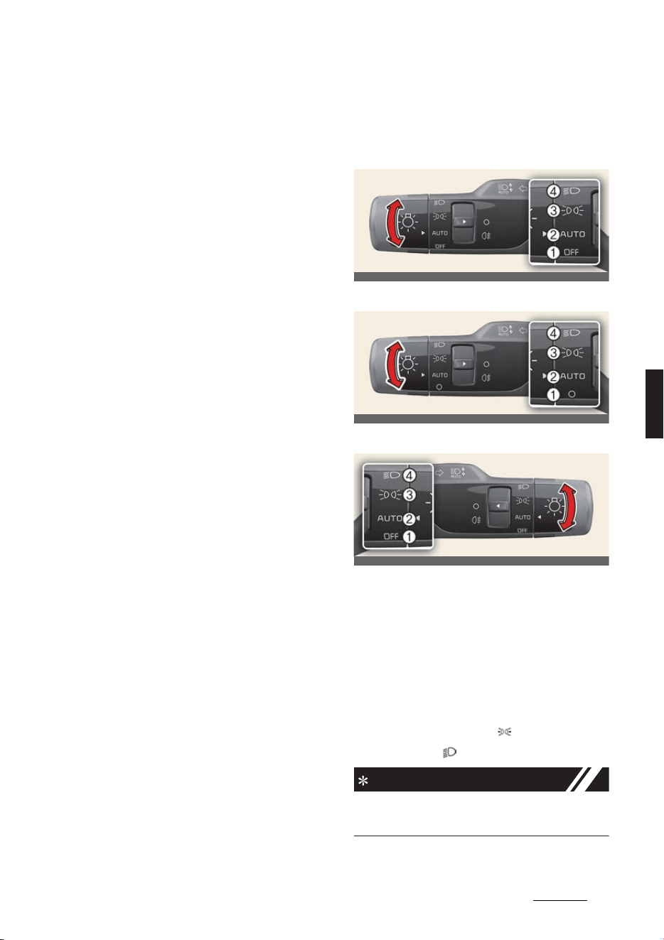
61
5
5
Features of your vehicle Lighting
- Press the lock button on the key
twice
- Turn the headlamp switch to OFF
position
Operating condition(s)
僅 The vehicle is in ACC or OFF position
with the headlamps ON
僅 The driver's door is opened and
closed
Daytime Running Light (DRL)
Operating condition(s)
僅 The vehicle is in the ON position
僅 The headlamp switch is in the OFF
position
僅 The parking brake is disengaged
Traffic change (For Europe)
The distribution of light from low-beam
headlamps is asymmetrical. If you go to
a country with opposite traffic direction,
this asymmetrical distribution will dazzle
drivers in oncoming vehicles. To avoid
dazzling other drivers, ECE regulations
require various technical solutions (e.g.,
automatic change system, adhesive
sheet, downward aim). This vehicle's
headlamps are designed not to dazzle
oncoming drivers. Thus, you need not
change your headlamps when in a coun
-
try with opposite traffic direction.
Lighting controls
Operating lights
Type A
Type B
Type C
Operation
1
OFF (O)
2
AUTO
僅 The headlamps and tailamps will
turn ON or OFF automatically
depending on the external ambient
light level.
3
Position & Taillamp ( )
4
Low beam ( )
INFORMATION
The vehicle must be in the ON position
to turn on the headlights.
OCV041050L
OCV041086L
OCV041050R
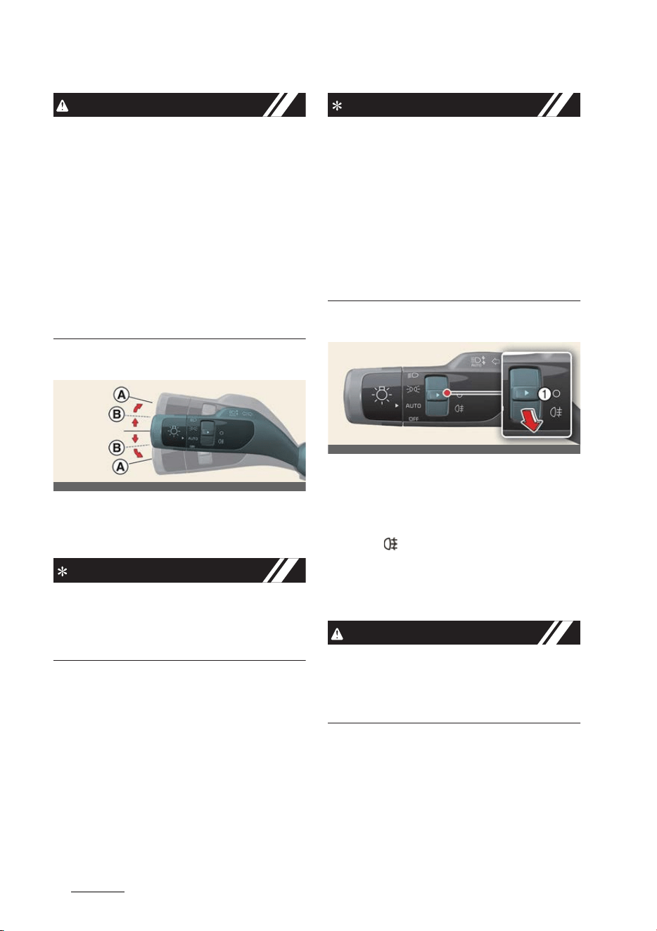
Features of your vehicle
625
Lighting
CAUTION
僅 Never place anything over the sensor
located on the instrument cluster as
this will ensure better auto-light sys
-
tem control.
僅 Don't clean the sensor using a window
cleaner, the cleaner may leave a light
film which could interfere with sensor
operation.
僅 If your vehicle has window tint or
other types of metallic coating on the
front windshield, the Auto light system
may not work properly.
Operating the turn signals
Operation
僅 Move the lever up or down (A).
NOTICE
If an indicator flash is abnormally quick
or slow, a bulb may be burned out or
have a poor electrical connection in the
circuit.
One-Touch Lane-Change func
-
tion
Operation
僅 Move the turn signal lever up or down
(B).
僅 Release the lever.
INFORMATION
僅 You can activate or deactivate the
One Touch Turn Signal function or
choose the number of blinking (3, 5,
or 7) by selecting
Settings
→
Vehicle
→
Lights
→
One-touch turn indica
-
tor
.
僅 If an indicator stays on and does not
flash or if it flashes abnormally, one of
the turn signal bulbs may be burned
out and will require replacement.
Operating the fog lights
Operation
僅 Turn the fog light switch (1) to the
dedicated position.
僅Rear: ( )
Operating condition(s)
僅 The headlamps are turned ON.
CAUTION
When in operation, the fog lights con
-
sume large amounts of vehicle electrical
power. Only use the fog lights when visi
-
bility is poor.
OCV041051L
OCV041052L
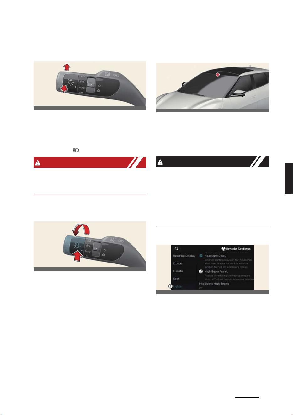
63
5
5
Features of your vehicle Lighting
Operating the high-beam head
-
lamps
Operation
僅 Push the lever to use high beam.
僅 Pull the lever towards you to flash the
headlights ( ).
WARNING
Do not use high beam when there are
other vehicles. Using high beam could
obstruct the other driver's vision.
High Beam Assist (HBA) (if
equipped)
High Beam Assist is a function that auto
-
matically adjusts the headlamp range
(switches between high beam and low
beam) depending on the brightness of
detected vehicles and certain road con
-
ditions.
Detecting sensor
Front view camera
The front view camera is used as a
detecting sensor to detect ambient light
and brightness while driving. Refer to
the picture above for the detailed loca
-
tion of the detecting sensor.
CAUTION
Always keep the front view camera in
good condition to maintain optimal per
-
formance of High Beam Assist.
For more details on the precautions of
the front view camera, refer to "Forward
Collision-Avoidance Assist (FCA) (if
equipped)" on page 6-43.
High Beam Assist Setting
A:
Vehicle Settings
1 Lights
2 HBA (High Beam Assist)
With the vehicle in the ON position,
select
Settings
→
Vehicle
→
Lights
→
HBA (High Beam Assist)
from the Set
-
tings menu to turn on High Beam Assist
function.
OCV041053L
OCV041054L
OCV041055L
OCV041522L
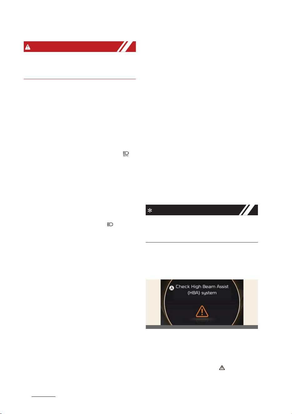
Features of your vehicle
645
Lighting
WARNING
For your safety, change the Settings
after parking the vehicle at a safe loca
-
tion.
High Beam Assist operation
僅 After selecting
HBA (High Beam
Assist)
in the
Settings
menu, High
Beam Assist will operate by following
the procedure below.
- Place the headlamp switch in the
AUTO position and push the head
-
lamp lever towards the instrument
cluster. The High Beam Assist ( )
indicator light will illuminate on the
cluster and the function will be
enabled.
- When the function is enabled, high
beam will turn on when vehicle
speed is above 40 km/h (25 mph).
When vehicle speed is below 25
km/h (15 mph), high beam will not
turn on. The High Beam ( ) indica
-
tor light will illuminate on the clus
-
ter when high beam is on.
僅 When High Beam Assist is operating,
if the headlamp lever or switch is
used, the function operates as follow:
- If the headlamp lever is pulled
towards you when the high beam is
off, the high beam will turn on.
When you let go of the headlamp
lever, High Beam Assist will turn on
again.
- If the headlamp lever is pulled
towards you when the high beam is
on, the low beam will turn on and
High Beam Assist will be canceled.
- If you push the light switch towards
the instrument cluster, high beam is
turned on and High Beam Assist is
released.
- If the headlamp switch is placed
from AUTO to another position
(headlamp/position/off), High
Beam Assist will turn off and the
corresponding lamp will turn on.
僅 When High Beam Assist is operating,
high beam switches to low beam if
any of the following conditions occur:
- When the headlamp of an oncom
-
ing vehicle is detected.
- When the tail lamp of a vehicle in
front is detected.
- When the headlamp or tail lamp of
a motorcycle or a bicycle is
detected.
- When the surrounding ambient
light is bright enough that high
beams are not required.
- When streetlights or other lights are
detected.
NOTICE
僅 Depending on the instrument cluster
specifications or theme, images or
colors may be displayed differently.
High Beam Assist Malfunction
and limitations
High Beam Assist Malfunction
A:
Check High Beam Assist (HBA) sys
-
tem
When High Beam Assist is not working
properly, the warning message will
appear and warning light ( ) will illumi
-
nate on the cluster. We recommend that
OCV051213L

65
5
5
Features of your vehicle Lighting
you have your vehicle inspected by an
authorized Kia dealer/service partner.
Limitations of High Beam Assist
僅 Light from a vehicle is not detected
because of lamp damage, or because
it is hidden from sight, etc.
僅 Headlamp of a vehicle is covered with
dust, snow or water.
僅 A vehicle's headlamps are off but the
fog lamps are on and etc.
僅 There is a lamp that has a similar
shape as a vehicle's lamp.
僅 Headlamps have been damaged or
not repaired properly.
僅 Headlamps are not aimed properly.
僅 Driving on a narrow curved road,
rough road, uphill or downhill.
僅 Vehicle in front is partially visible on a
crossroad or curved road.
僅 There is a traffic light, reflecting sign,
flashing sign or mirror ahead.
僅 There is a temporary reflector or flash
ahead (construction area).
僅 The road conditions are bad such as
being wet, iced or covered with snow.
僅 A vehicle suddenly appears from a
curve.
僅 The vehicle is tilted from a flat tire or
is being towed.
僅 Light from a vehicle is not detected
because of exhaust fume, smoke, fog,
snow, etc.
NOTICE
For more details on the limitations of the
front view camera, refer to "Forward Col
-
lision-Avoidance Assist (FCA) (if
equipped)" on page 6-43.
WARNING
僅 At times, High Beam Assist may not
work properly. The function is for your
convenience only. It is the responsibil
-
ity of the driver for safe driving prac
-
tices and always check the road
conditions for your safety.
僅 When High Beam Assist does not
operate normally, change the head
-
lamp position manually between high
beam and low beam.
Intelligent front-lighting system
(IFS) (if equipped)
Intelligent Front-Lighting System
secures a clear view for the driver with
the high beam on while driving at night.
System setting
A:
Lights
1 Intelligent front-lighting
2 Faster Than 60 km/h
3 Faster Than 40 km/h
4 Faster Than 20 km/h
5 Off
With the vehicle in the ON position,
select
Settings
→
Vehicle
→
Lights
→
Intelligent front-lighting
in the Settings
menu to turn on Intelligent Front-Light
-
ing System and deselect to turn off the
system.
OCV041187L
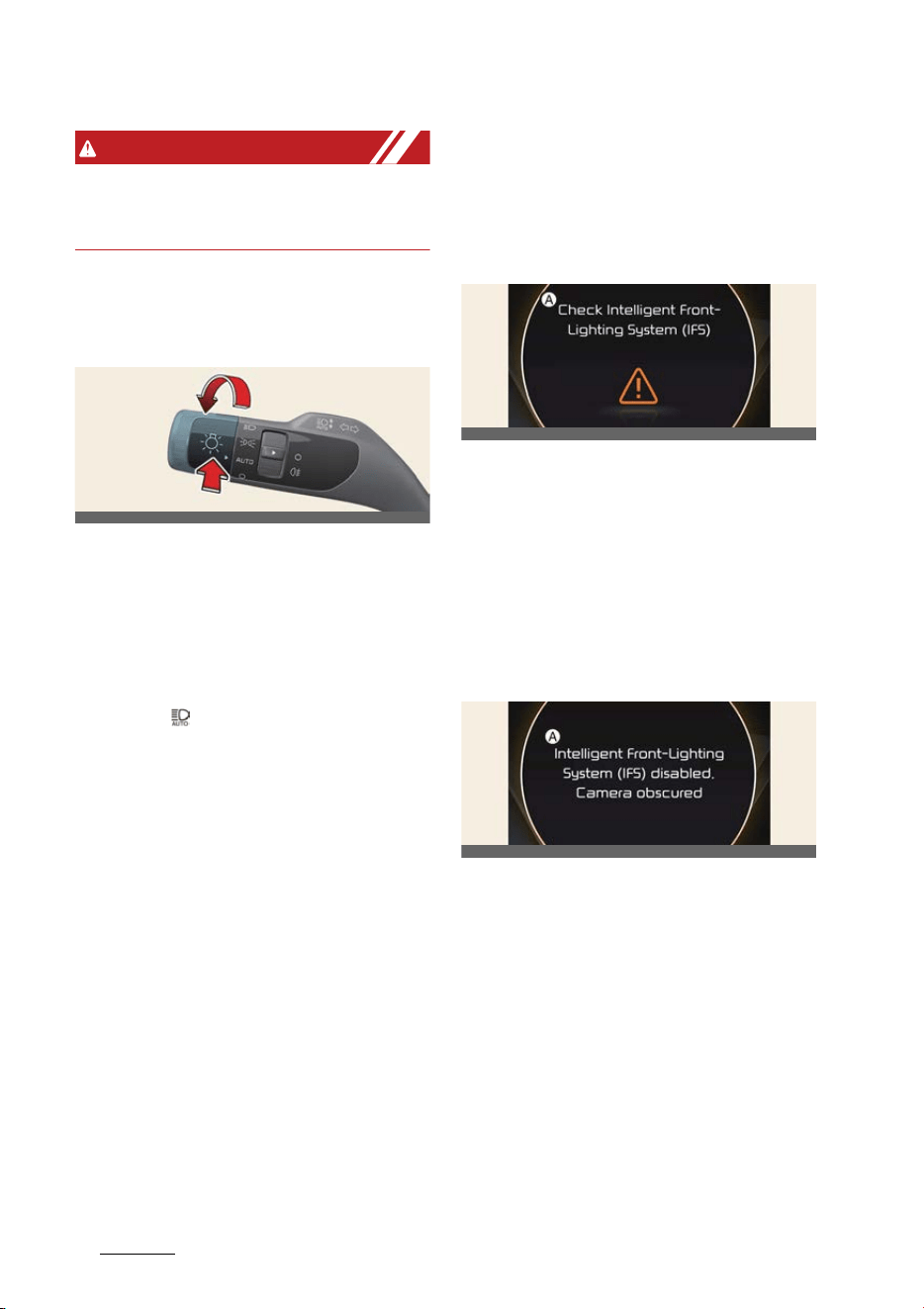
Features of your vehicle
665
Lighting
WARNING
For your safety, change the Settings
after parking the vehicle at a safe loca
-
tion.
System operation
Display and control
Intelligent Front- Lighting System will
operate by following the procedure
below.
僅 Place the headlamp switch in the
AUTO position and push the head
lamp lever toward the instrument
cluster. The Intelligent Front-Lighting
System ( ) indicator will illuminate on
the cluster and the system will be
enabled.
僅 When the system is enabled, the Intel
-
ligent Front-Lighting System will oper
-
ate according to the set speed in the
infotainment system. The initial sys
-
tem is set to work when vehicle speed
is above 40 km/h (25 mph).
僅 The high beam LED partially turns off
if an oncoming vehicle or a vehicle
ahead is detected by the front view
camera.
僅 If Intelligent Front-Lighting System
detects an oncoming vehicle or a
vehicle ahead while driving at high
speed (approximately above 100 km/
h (60 mph), the driver's side head
-
lamp will turn off and only the passen
-
ger's side headlamp will be controlled
by the system.
System malfunction and limita
-
tions
System malfunction
A:
Check Intelligent Front-Lighting
System (IFS)
When Intelligent Front-Lighting System
is not working properly, the warning
message will come on for a few second
on the cluster. After the message disap
-
pears, the warning lights
AFS
will illumi
-
nate. We recommend that you have your
vehicle inspected by an authorized Kia
dealer/service partner.
A:
Intelligent Front-Lighting System
(IFS) disabled. Camera obscured
When the front view camera is covered
with dirt, snow, or debris, Intelligent
Front-Lighting System may temporarily
not work properly. If this occurs, a warn
-
ing message will appear on the cluster.
The system will operate normally when
such dirt, snow or debris is removed.
Intelligent Front-Lighting System may
not properly operate in an area (e.g.
open terrain) where any objects or vehi
-
OCV041054L
OCV041190L
OCV041191L
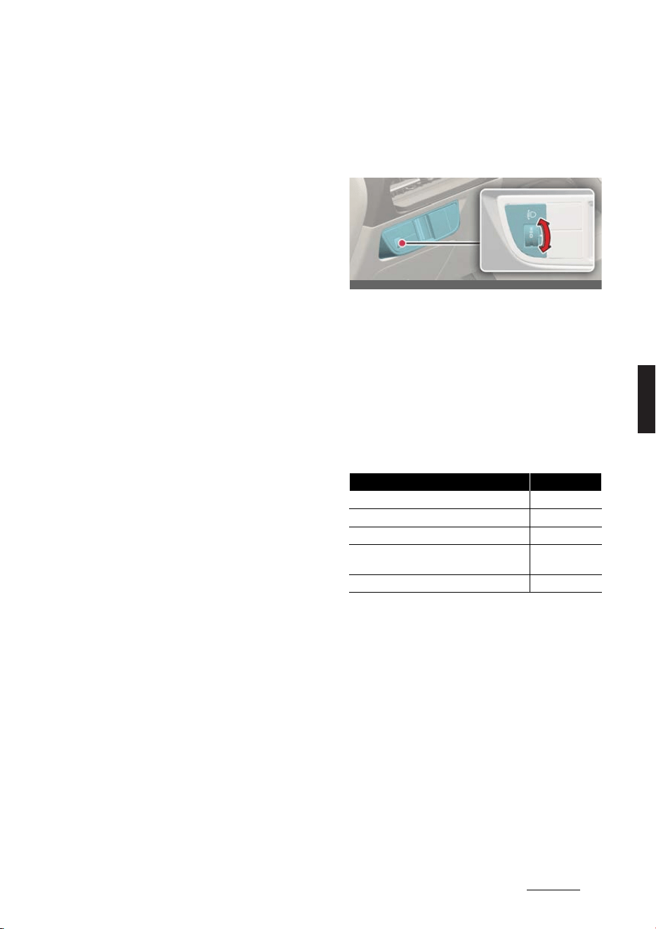
67
5
5
Features of your vehicle Lighting
cles are not detected after turning on
the vehicle.
Also, even though a warning message
does not appear on the cluster, the sys
-
tem may not properly operate.
Limitations of the system
Intelligent Front-Lighting System may
not work properly in the following situa
-
tions.
僅 Light from a vehicle is not detected
because of lamp damage, or because
it is hidden from sight, etc.
僅 Headlamp of a vehicle is covered with
dust, snow or water.
僅 There is a lamp that has a similar
shape as a vehicle's lamp.
僅 A vehicle's headlamps are off but the
fog lamps are on and etc.
僅 Headlamps have been damaged or
not repaired properly.
僅 Headlamps are not aimed properly.
僅 Driving on a narrow curved road,
rough road, uphill or downhill.
僅 Vehicle in front is partially visible on a
crossroad or curved road.
僅 There is a traffic light, reflecting sign,
flashing sign or mirror ahead.
僅 There is a temporary reflector or flash
ahead (construction area).
僅 The road conditions are bad such as
being wet, iced or covered with snow.
僅 A vehicle suddenly appears from a
curve.
僅 The vehicle is tilted from a flat tire or
is being towed.
僅 There are many street lights or the
ambient light is bright.
僅 Light from a vehicle is not detected
because of exhaust fume, smoke, fog,
snow, etc.
僅 The front windshield is covered with
foreign substance.
Headlamp leveling adjustment (if
equipped)
Operation
僅 The higher the number of the switch
position is, the lower the headlight
beam level.
僅 Always keep the headlamp beam at
the proper leveling position, or your
headlamps may dazzle other road
users.
Loading condition Switch position
Driver only 0
Driver + Front passenger 0
Full set of passengers (including driver) 1
Full set of passengers (including driver) +
Maximum permissible loading
2
Driver + Maximum permissible loading 3
OCV041057L
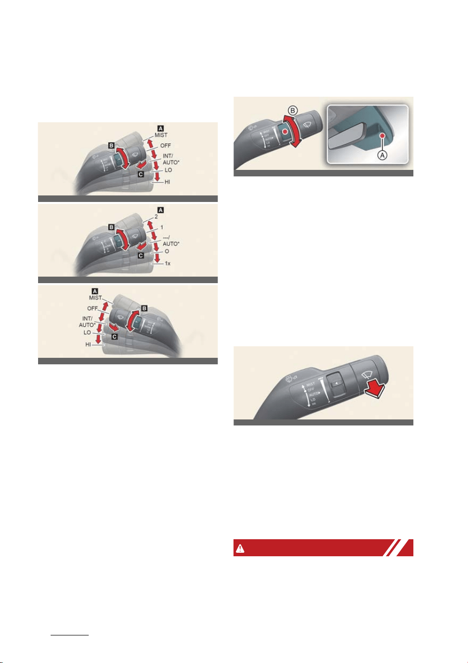
Features of your vehicle
685
Wipers and washers
Wipers and washers
Wipers
Controlling the wipers
Operation
僅 A: Front wiper speed control
- MIST (1x): Single wipe
-OFF (
0
): Off
-AUTO: Auto control wipe
- LO (1): Low wiper speed
- HI (2): High wiper speed
僅 B: Auto control wipe time adjustment
僅 C: Wash with brief wipes
Controlling the wipers automati
-
cally
A: Rain sensor
B: Wiper speed control switch
Operation
僅 The rain sensor (A) senses the amount
of rainfall and adjusts the wiper speed
interval accordingly.
僅 Turn the speed control switch (B) to
adjust the wiper speed.
Washers
Controlling the washers
Operation
1. Move the wiper speed control switch
to OFF (
0
) position.
2. Pull the lever gently toward you to
spray washer fluid on the windshield.
3. Operate the wipers so they perform
several cycles.
WARNING
Do not use the washer in freezing tem
-
peratures without first warming the
windshield with the defrosters; the
OCV041056L
OCV041588L
OCV041056R
OCV041058L
OCV041059L

69
5
5
Features of your vehicle Wipers and washers
washer solution could freeze on the
windshield and obscure your vision.
CAUTION
僅 When the EV button is in ON position
and the windshield wiper switch is
placed in the AUTO mode, use caution
in the following situations to avoid any
injury to the hands or other parts of
the body:
- Do not touch the upper end of the
windshield glass facing the rain
sensor.
- Do not wipe the upper end of the
windshield glass with a damp or
wet cloth.
- Do not put pressure on the wind
-
shield glass.
僅 When washing the vehicle, set the
wiper switch in the OFF (
0
) position to
stop the auto wiper operation.
The wiper may operate and be dam
-
aged if the switch is set in the AUTO
mode while washing the vehicle.
僅 Do not remove the sensor cover
located on the upper end of the driver
or passenger side windshield glass.
Damage to system parts could occur
and may not be covered by your vehi
-
cle warranty.
僅 When starting the vehicle in winter,
set the wiper switch in the OFF (
0
)
position. Otherwise, wipers may oper
-
ate and ice may damage the wind
-
shield wiper blades. Always remove all
snow and ice and defrost the wind
-
shield properly prior to operating the
windshield wipers.
僅 When tinting the windshield, be care
-
ful of any fluid getting into the sensor
located in the top center of the front
windshield. It may damage the related
parts.
僅 To prevent possible damage to the
washer pump, do not operate the
washer when the fluid reservoir is
empty.
僅 To prevent possible damage to the
wipers or windshield, do not operate
the wipers when the windshield is dry.
僅 To prevent damage to the wiper
blades, do not use gasoline, kerosene,
paint thinner, or other solvents on or
near them.
僅 To prevent damage to the wiper arms
and other components, do not
attempt to move the wipers manually.
僅 To prevent possible damage to the
wipers and washer system, use anti-
freezing washer fluids in the winter
season or cold weather.
NOTICE
If there is heavy accumulation of snow
or ice on the windshield, defrost the
windshield for about 10 minutes, or until
the snow and/or ice is removed before
using the windshield wipers to ensure
proper operation. If you do not remove
the snow and/or ice before using the
wiper and washer, it may damage the
wiper and washer system.
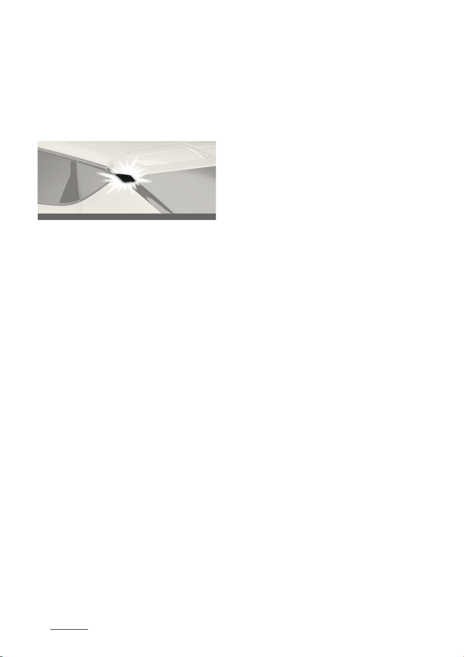
Features of your vehicle
705
Welcome system
Welcome system
The surroundings or the interior will be
lit up when the driver approaches or
exits the vehicle.
Body silhouette lamp
Operation
僅 Body silhouette lamp will turn on for
approximately 15 seconds.
Operating condition(s)
僅 All the doors (and tailgate) are closed
and locked.
Headlamp escort function
Operation
僅 The headlamps remain on for approx
-
imately 5 minutes if the vehicle is in
ACC or OFF position with the head
-
lamps ON.
僅 The headlamps turn off after 15 sec
-
onds if the driver door is opened and
closed.
Operating condition(s)
僅 Vehicle is in the ACC position.
僅 The driver door is opened and closed.
Interior lighting
Operation
僅 The room lamp will turn on.
- For approximately 30 seconds.
Operating condition(s)
僅 The map lamp switch is in DOOR
mode.
僅 All the doors (and tailgate) are closed
and locked.
OCV031092L
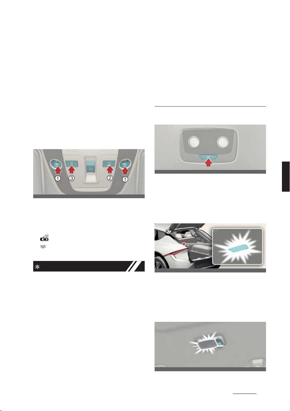
71
5
5
Features of your vehicle Interior lights
Interior lights
Automatic turn-off function
Operation
僅 The interior lights will turn off.
- After approximately 20 minutes.
Operating condition(s)
僅 The vehicle is in the OFF position.
僅 The lights are in the ON position.
Map lamp
Operation
僅 Press the lamp (1) to turn the map
lamp ON.
僅 (2): DOOR mode
僅 (3): Front and rear room lamps on
and off.
INFORMATION
僅 The map lamp and room lamp come
on approximately 30 seconds.
- When a door is opened.
- When doors are unlocked with a
smart key as long as the doors are
not opened.
僅 The map lamp and room lamp will
stay on
- If a door is opened with the vehicle
in the ACC or OFF position. (5 min
-
utes)
- If the door is opened with the vehi
-
cle in the ON position. (continu
-
ously)
僅 The map lamp and room lamp will go
out
- If the vehicle is changed to the ON
position or all doors are locked.
(immediately)
Room lamp
Operation
僅 Press the switch to turn the room
lamp on or off.
Luggage space lamp
Operation
僅 Open the tailgate. The lamp will turn
on.
Vanity mirror lamp
OCV041061L
OCV041063L
OCV041062L
OCV041064L
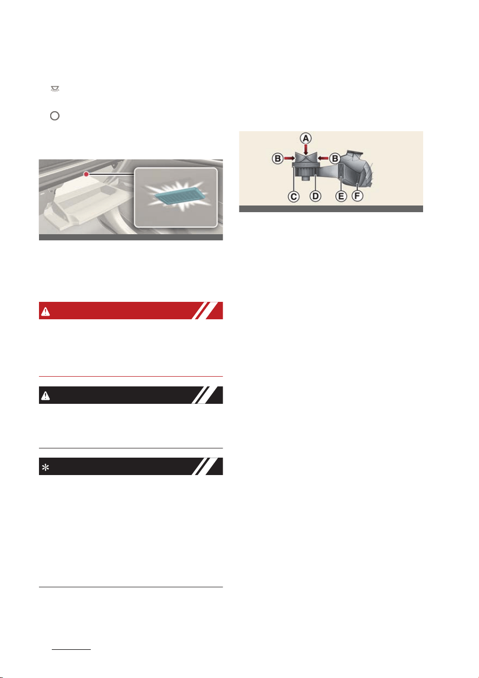
Features of your vehicle
725
Climate control system
Operation
僅 : The lamp will turn on if this button
is pressed.
僅 : The lamp will turn off if this button
is pressed again.
Glove box lamp
Operation
僅 The glove box lamp comes on when
the glove box is opened.
WARNING
Do not use the interior lights when driv
-
ing in the dark. Accidents could happen
because the view may be obscured by
interior lights.
CAUTION
Do not use the interior lights for
extended periods when the vehicle is not
running. It may cause battery discharge.
NOTICE
僅 The DOOR mode and ROOM mode
can not be selected at a time.
僅 To prevent unnecessary charging sys
-
tem drain, close the vanity mirror
cover after using the mirror.
僅 To prevent unnecessary charging sys
-
tem drain, close the glove box
securely after using the glove box.
Climate control system
Climate control system compo
-
nents
A: Outside air
B: Recirculated air
C: Climate control air filter
D: Blower
E: Evaporator core
F: Heater core
The climate control air filter installed
behind the front trunk filters the dust or
other pollutants that come into the vehi
-
cle from the outside through the heating
and air conditioning system.
If dust or other pollutants accumulate in
the filter over a period of time, the air
flow from the air vents may decrease.
This leads to moisture accumulating on
the inside of the windshield even when
the outside (fresh) air position is
selected.
If this happens, have the climate control
air filter replaced by a professional
workshop. Kia recommends visiting an
authorized Kia dealer/service partner.
OCV041065L
ONQ5EP041426L
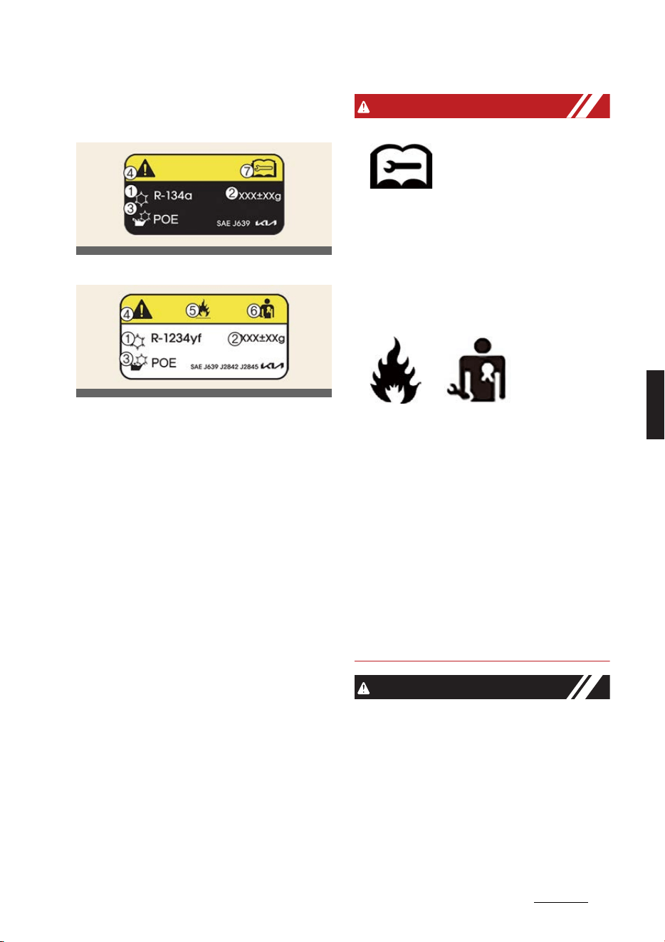
73
5
5
Features of your vehicle Climate control system
Air conditioning refrigerant label
Example Type A
Example Type B
1
Classification of refrigerant
2
Amount of refrigerant
3
Classification of Compressor lubricant
4
Caution
5
Flammable Refrigerant
6
A registered technician must service
the air conditioning system
7
Service manual
You can find out which air conditioning
refrigerant is applied your vehicle at the
label inside of the motor room.
Refer to "Refrigerant label" on page 9-9
for more detail on the location of air con
-
ditioning refrigerant label.
WARNING
僅 Vehicles equipped with R-134a
Because the refrigerant is
at very high pressure, the
air conditioning system
should only be serviced by
trained and certified technicians. It is
important that the correct type and
amount of oil and refrigerant is used.
Otherwise, it may cause damage to
the vehicle and personal injury.
僅 Vehicles equipped with R-1234yf*
Since the refrigerant is mildly flamma
-
ble and operated at high pressure, the
air conditioning system should only
be serviced by trained and certified
technicians.
It is important that the correct type
and amount of oil and refrigerant are
used. All refrigerants should be
reclaimed with proper equipment.
Venting refrigerants directly to the
atmosphere is harmful to individuals
and environment. Failure to heed
these warnings can lead to serious
injuries.
CAUTION
僅AC repair
It is important that the correct type
and amount of oil and refrigerant is
used, otherwise, damage to the vehi
-
cle may occur. To prevent damage,
the air conditioning system in your
vehicle should only be serviced by
trained and certified Kia technicians.
OCV041067L
OCV041068L

Features of your vehicle
745
Climate control system
僅 The air conditioning system should
only be used with the windows and
sunroof closed to prevent condensa
-
tion inside the vehicle that may cause
damage to electrical components.
NOTICE
僅 Replace the filter according to the
maintenance schedule. If the vehicle
is being driven in severe conditions
such as dusty or rough roads, more
frequent air conditioner filter inspec
-
tions and changes are required.
僅 When the air flow rate suddenly
decreases, have the system checked
by a professional workshop. Kia rec
-
ommends visiting an authorized Kia
dealer/service partner.

75
5
5
Features of your vehicle Automatic climate control system
Automatic climate control system
1
Driver's temperature control knob
2
Passenger's temperature control knob
3 AUTO
(automatic control) button
4
OFF button
5
Fan speed control button
6
Mode selection button
7
Front-windshield defroster button
8
Rear-window defroster button
9 SYNC
button
10
Air intake control button
11
Air conditioning
A/C
button
12
Driver only select button
13 HEAT
button
14
Infotainment/climate control mode switching button
OCV041312L
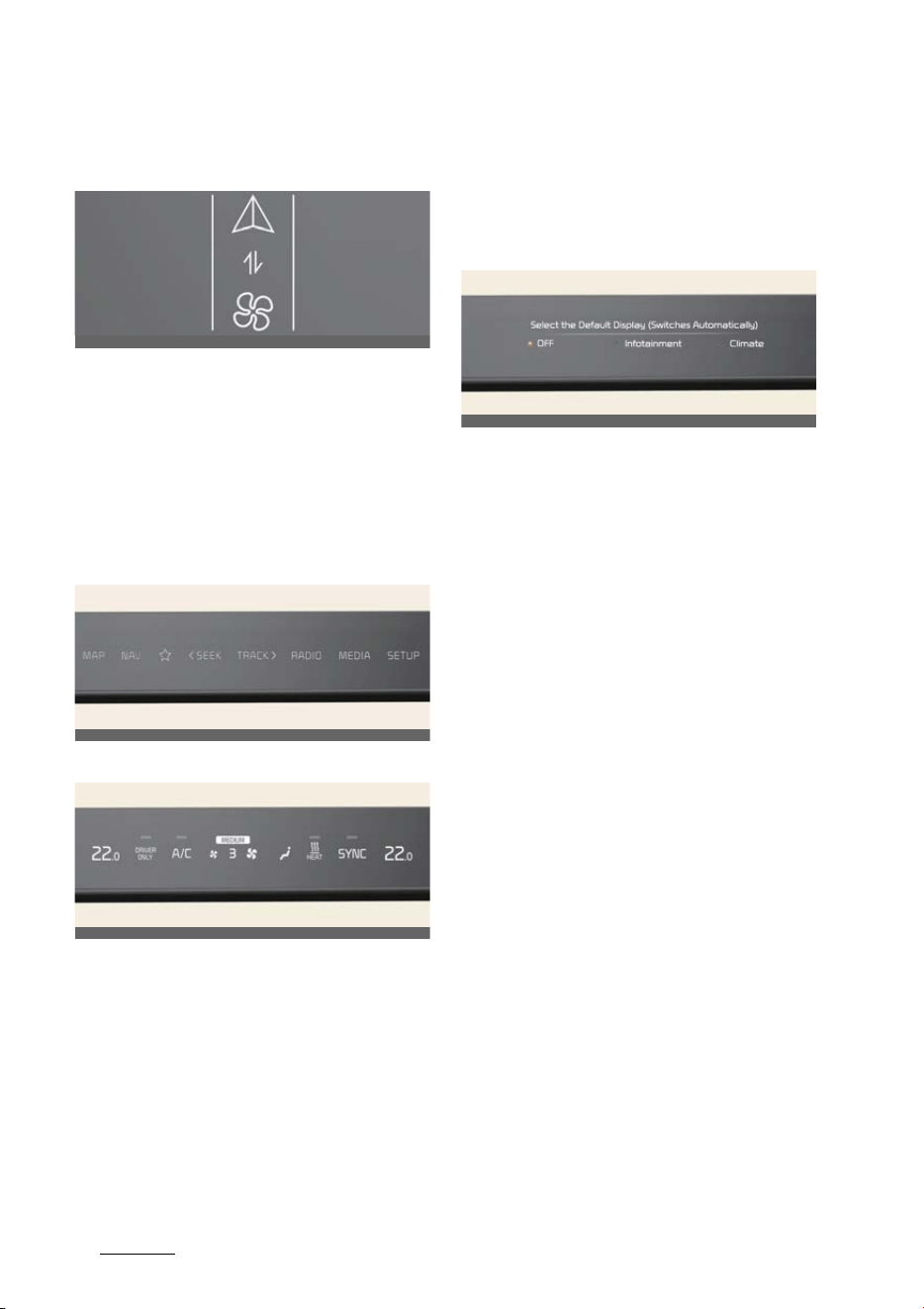
Features of your vehicle
765
Automatic climate control system
Using the infotainment/climate
switchable controller
Press the button on the switchable con
-
troller to switch between infotainment
system or climate control panel.
Press and hold the button to select the
default mode for the control panel.
Switching between panels
Infotainment control panel
Climate control panel
Press the button on the switchable con
-
troller to select the desired control panel.
The selected control panel icon will be
illuminated and the control panel will be
changed.
僅 The knob display will be illuminated
according to the selected control
panel mode.
僅 When the vehicle is in the ACC posi
-
tion, only the infotainment system will
be activated.
Setting the default mode
Press and hold the button to select the
default mode for the control panel.
僅 After the setting, the control panel will
return to the default mode after a cer
-
tain period of time even if the control
panel is switched to the different
mode.
僅 If the mode is set to 'OFF', the control
panel will display the mode used
recently.
OCV041315
OCV041316
OCV041548L
OCV041559L
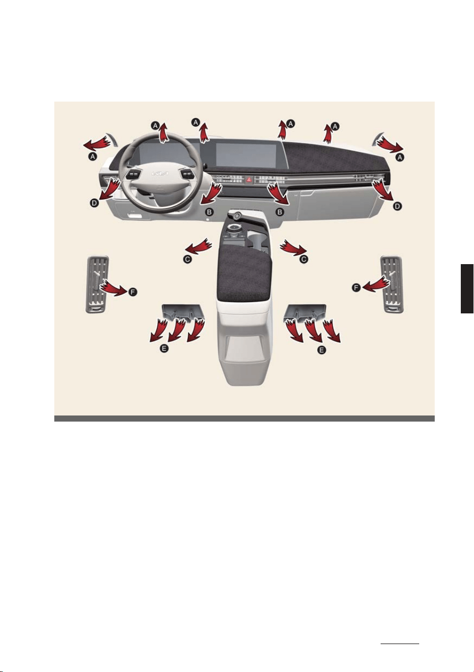
77
5
5
Features of your vehicle Automatic climate control system
Operating the climate control system
Left-hand drive
OCV041300L
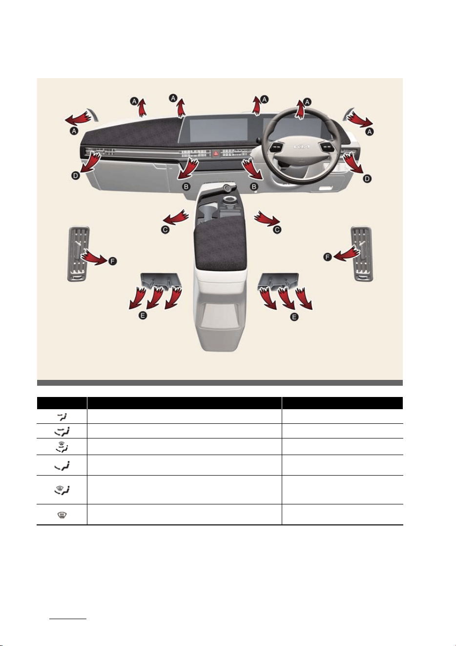
Features of your vehicle
785
Automatic climate control system
Right-hand drive
Mode Operation Air flow
Air flow is directed toward the upper body and face. B, D, F
Air flow is directed towards the face and the floor. B, C, D, F
Air flow is directed toward the face, the floor and the windshield. A, B, C, D, E, F
Most of the air flow is directed to the floor, with a small amount of air
directed to the windshield, side-window defrosters, and side air vents.
A, C, D, E
Most of the air flow is directed to the floor and the windshield, with a
small amount directed to the side-window defrosters and side air
vents.
A, C, D, E
Most of the air flow is directed to the windshield, with a small amount
of air directed to the side-window defrosters and side air vents.
A, D
OCV041300R
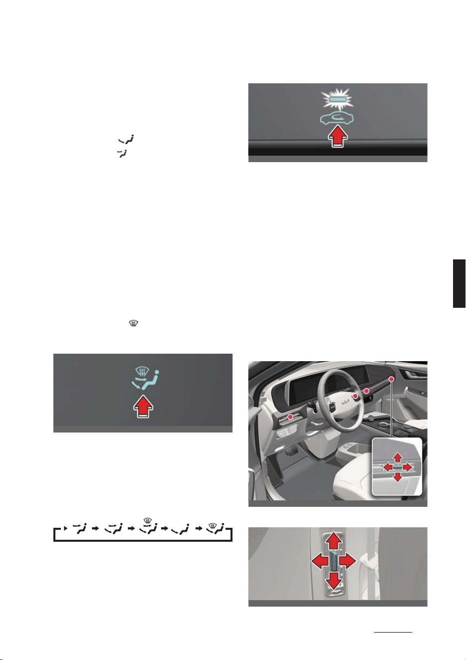
79
5
5
Features of your vehicle Automatic climate control system
Operation
1. Start the vehicle.
2. Set the mode-selection buttons as
desired. To improve the effectiveness
of heating and cooling:
僅Heating: ( )
僅 Cooling: ( )
3. Set the temperature control to the
desired temperature level.
4. Set the air intake control to the posi
-
tion for outside (fresh) air if required.
5. Set the position of the fan speed con
-
trol so that it runs at the desired
speed.
6. If desired, turn the air conditioning ON
with the temperature set high in order
to dehumidify the air before it enters
into the cabin.
If the windshield fogs up, select the
Front Defrost ( ) mode.
Selecting air flow modes
Operation
僅 Select the direction of the air flow
through the ventilation system.
The air flow outlet ports are enabled
in the following sequence:
Controlling the air intake
Operation
僅 Select the outside (fresh) air position
or recirculated air position.
僅 Outside (fresh) air position: Air enters
the vehicle from outside. The indicator
light will turn off.
僅Recirculated air position: Air from the
passenger compartment will be
drawn back into the heating system.
The indicator light illuminates.
Controlling the instrument panel
vents
Front
Rear
OCV041301L
OCV041302L
OCV041304L
OCV041322L
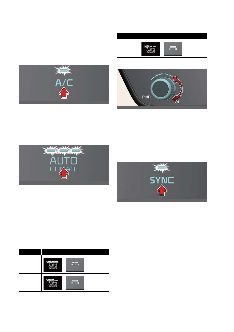
Features of your vehicle
805
Automatic climate control system
Operation
僅 Adjust the direction of air delivered
from the vents.
Air conditioning A/C
Operation
僅 Press the
A/C
button.
Controlling heating and air condi
-
tioning automatically
Operation
1. Set the desired temperature.
2. Press the
AUTO
button to control:
僅Mode
僅 Fan speed
僅Air intake
僅 Air conditioning
Controlling the temperature
Operation
僅 Turn the knob left or right to the
desired temperature.
Adjusting the driver and passen
-
ger side temperature to the same
value
Operation
1. Press the
SYNC
button.
2. Turn the driver's side temperature
control knob.
Changing temperature scale
Operation
僅Go to
Settings
→
Units
→
Tempera
-
ture
on the infotainment system.
Level Indicator LCD Display Air flow
High
1~8 (EU)
2~8
Medium 1~6
OCV041303L
OCV041303
Low 1~4
Level Indicator LCD Display Air flow
OCV041305L
OCV041307L
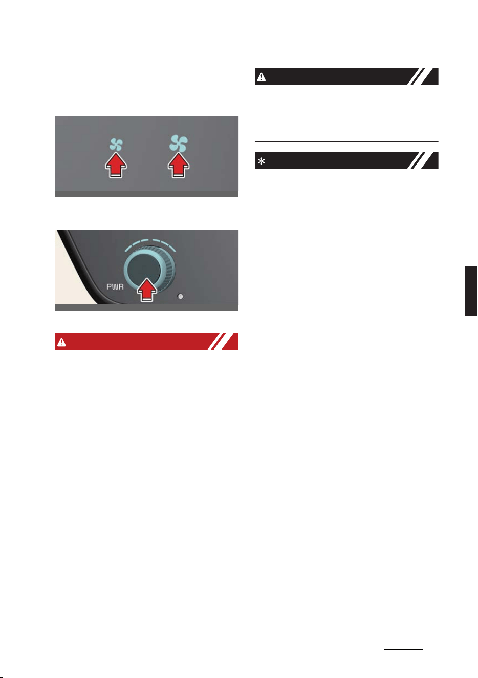
81
5
5
Features of your vehicle Automatic climate control system
Controlling fan speed
Operation
僅 Press the left or right button to adjust
the speed.
僅 Press the knob to turn the blowers off.
WARNING
僅 Continuously using the climate control
system in the recirculated air position
may allow humidity to increase inside
the vehicle which may fog the glass
and obscure visibility.
僅 Do not sleep in a vehicle with the air
conditioning or heating system on. It
may cause serious harm or death due
to a drop in the oxygen level and/or
body temperature.
僅 Continuously using the climate control
system in the recirculated air position
can cause drowsiness or sleepiness,
and loss of vehicle control. Set the air
intake control to the outside (fresh) air
position as much as possible while
driving.
CAUTION
Operating the blower when the EV but
-
ton is in the ON position could cause the
battery to discharge. Operate the blower
when the vehicle is running.
NOTICE
僅 Prolonged operation of the heater in
the recirculated air position (without
air conditioning selected) may cause
fogging of the windshield and side
windows and make the air in the pas
-
senger compartment stale. In addi
-
tion, prolonged use of the air
conditioning with the re circulated air
position selected will result in exces
-
sively dry air in the passenger com
-
partment.
僅 To turn the automatic operation off,
select any button or switch of the fol
-
lowing:
- Mode selection button
- Air conditioning button
- Front-windshield defroster button
(Press the button one more time to
deselect the front windshield
defroster function. The AUTO sign
will illuminate on the information
display once again.)
- Fan speed control knob
The selected function will be con
-
trolled manually while other functions
operate automatically.
僅 For your convenience and to improve
the effectiveness of the climate con
-
trol, use the AUTO button and set the
temperature to 22 °C (72 °F).
僅 Never place anything over the sensor
located on the instrument panel to
ensure better control of the heating
and cooling system.
OCV041306L
OCV041308L
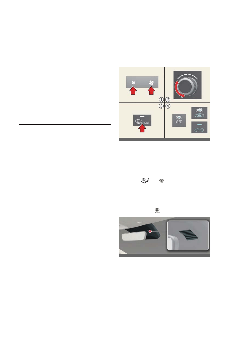
Features of your vehicle
825
Windshield defrosting and defogging
僅 To help improve microphone voice
input sound, fan speed may automati
-
cally slow down for a couple of min
-
utes when you activate voice
recognition or hands free.
僅 When charging or right after charging
the high voltage battery, the cooling
will be made using air conditioner sys
-
tem in order to control the high volt
-
age battery temperature.
At this time, the noise might occur by
the air conditioner compressor and
cooling fan, but this is due to normal
operation.
Windshield defrosting and
defogging
Defrosting/defogging the wind
-
shield
Operation
1. Set the fan speed to the desired posi
-
tion.
2. Select the desired temperature.
3. Select ( ) or ( ).
4. Outside (fresh) air and air condition
-
ing will be selected automatically.
Auto defogging for automatic cli
-
mate control
Operation
僅 For Europe
- Air conditioning will turn ON.
- Air intake control will change to
Fresh mode.
OCV041323_4
OCV041309L
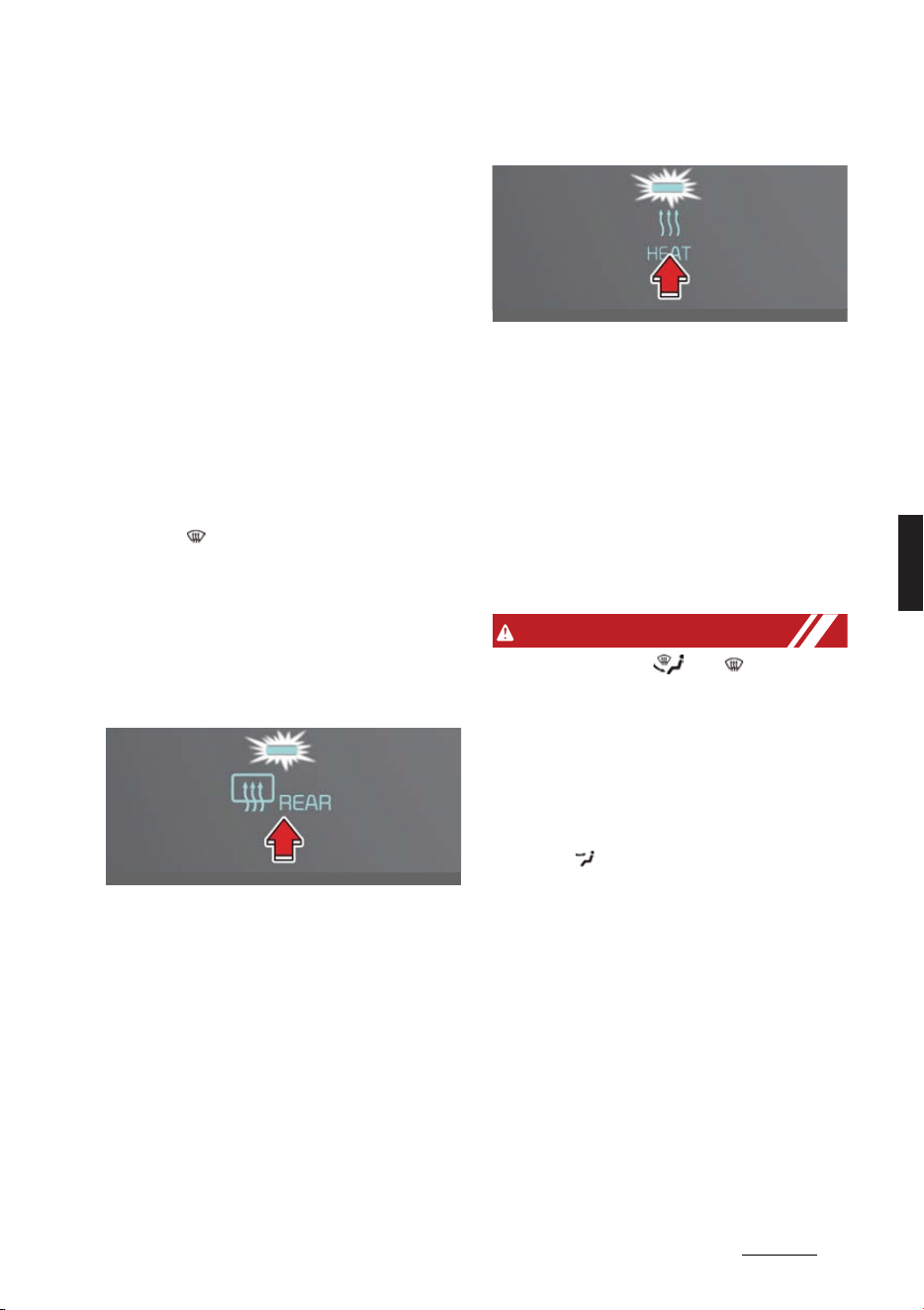
83
5
5
Features of your vehicle Windshield defrosting and defogging
- Mode will change to defrost to
direct airflow to the windshield.
- Fan speed will increase.
僅Except Europe
- Air conditioning will turn ON.
- Air intake control will change to
Fresh mode.
- Fan speed will increase.
- Mode will change to defrost to
direct airflow to the windshield
Canceling or resetting auto
defogging
Operation
僅 Press ( ) for 3 seconds.
- The button indicator will blink 3
times if canceled.
- The button indicator will blink 6
times if reset.
Rear window/outside mirror
defroster
Operation
僅 Press the Rear-window defroster but
-
ton. The indicator lights up when the
defroster is ON.
僅 It turns OFF after approximately 20
minutes or when the vehicle is in OFF
position.
Heat button
Operation
僅 Press the heat button. The indicator
illuminates when the heat function is
ON.
僅 The air conditioner and heater uses
energy from the battery. If you use
the heater or air conditioner for too
long, distance to empty can be
reduced due to too much power con
-
sumption.
WARNING
僅 Do not use the ( ) or ( ) position
during cooling operation in extremely
humid weather. The difference
between the temperature of the out
-
side air and the windshield could
cause the outer surface of the wind
-
shield to fog up, causing loss of visibil
-
ity. In this case, set the mode selection
to the ( ) position and fan speed con
-
trol to the lower speed.
僅 Continued use of the climate control
system operation in Recirculation
mode for a prolonged period of time
may cause drowsiness to the occu
-
pants in the cabin. This may lead to
loss of vehicle control which may lead
to an accident.
僅 Continued use of the climate control
system operation in Recirculation
mode with the air conditioning OFF
may allow humidity to increase inside
the cabin. This may cause condensa
-
OCV041310L
OCV041535L

Features of your vehicle
845
Windshield defrosting and defogging
tion to accumulate on the windshield
and obscure visibility.
僅 Do not sleep in your vehicle or remain
parked in your vehicle with the win
-
dows up and either the heater or the
air conditioning ON for prolonged
periods of time. Doing so may
increase the levels of carbon dioxide
in the cabin which may lead to serious
injury or death.
CAUTION
To prevent damage to the conductors
bonded to the inside surface of the rear
window, never use sharp instruments or
window cleaners containing abrasives to
clean the window.
NOTICE
僅 When the air conditioning is turned on
by Auto defogging system, if you try
to turn off the air conditioning, the air
conditioning will not be turned off.
僅 To maintain the effectiveness and
efficiency of the Auto Defogging Sys
-
tem, do not select Recirculation mode
while the system is operating.
僅 When the Auto Defogging System is
operating, the fan speed adjustment
knob, the temperature adjustment
knob, and the air intake control button
are all disabled.
僅 Do not remove the sensor cover
located on the upper end of the driver
side windshield glass.
Damage to system parts could occur
and may not be covered by your vehi
-
cle warranty.
僅 If the battery (12V) is discharged or
disconnected, Auto dehumidify set
-
tings will be reset. Readjust the set
-
tings to turning Auto dehumidify
option ON or OFF. For detailed infor
-
mation, refer to Navigation Quick Ref
-
erence Guide.
Auto. controls that use climate
control settings (if equipped)
The temperature of the driver’s seat
warmer, air ventilated seat and heated
steering wheel is automatically con
-
trolled depending on the inside and out
-
side temperature of the vehicle when
the vehicle is running.
Operation
僅 Select
Settings
→
Vehicle
→
Seat
→
Heating/Ventilation
→
Auto. Con
-
trols That Use Climate Control Set
-
tings
→
Steering wheel warmer
/
Seat warmer/ventilation
on the info
-
tainment screen.
僅 The heated steering wheel and seat
warmer/ventilation defaults to the
OFF position whenever the vehicle is
restarted. However, if the "Auto. con
-
trols that use climate control settings"
is ON, the heated steering wheel and
seat warmer/ventilation will turn on
and off depending on the inside and
outside temperature.
NOTICE
For detailed information, refer to Navi
-
gation Quick Reference Guide.
Smart ventilation (if equipped)
The smart ventilation system maintains
pleasant/fresh air conditioning inside the
passenger compartment by automati
-
cally detecting/controlling the tempera
-
ture and humidity level, when you drive
the vehicle with the climate control sys
-
tem in OFF position. When the smart
ventilation system starts to operate, the

85
5
5
Features of your vehicle Storage compartment
message appears for approximately 5
seconds.
The smart ventilation system stops
when:
僅 OFF button is selected.
僅 Any of the button of the climate con
-
trol is selected for operation.
NOTICE
The smart ventilation system may not
operate when the vehicle is driven at low
speed.
Storage compartment
Center console storage/glove box
Operation
僅 Pull the lid upward to open the center
console storage.
僅 Push the button of the glove box, and
it will open.
僅 There is a hook for charging cable fix
-
ing on the upper part of the center
console storage.
WARNING
僅 To reduce the risk of personal injury in
the event of sudden stop or collision,
do not place uncovered or unsecured
bottles, glasses, cans, etc., in the stor
-
age compartment while the vehicle is
in motion.
僅 Do not store glasses, gas lighter, por
-
table battery, canned beverage, spray
can, propane cylinder, cosmetic tube
or other flammable/explosive materi
-
als in the vehicle. These items may
catch fire and/or explode if the vehicle
is exposed to hot temperatures for
extended periods.
僅 To reduce the risk of injury in an acci
-
dent or sudden stop, always keep the
glove box door closed while driving.
OCV041069L_3
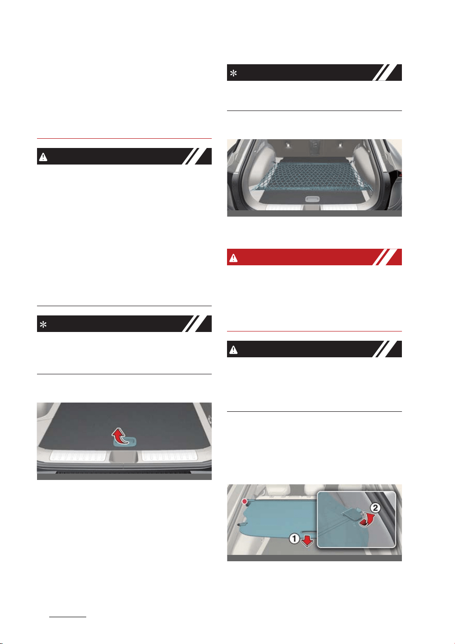
Features of your vehicle
865
Storage compartment
僅 Do not hang any other items (e.g.,
plastic bags) on the charging cable
fixing hook. It is dangerous to hang
objects other than intended use, as
the items may fall while driving and
interfere with the brake pedal.
CAUTION
僅 To avoid possible theft, do not leave
valuables in the storage compart
-
ment.
僅 Always keep the storage compart
-
ment covers closed while driving. Do
not attempt to place so many items in
the storage compartment that the
storage compartment cover cannot
close securely.
僅 Do not keep food in the glove box for
a long time.
NOTICE
If the armrest does not open in the event
of a collision, slide the armrest from the
driver's side to the passenger's side seat.
Luggage tray (if equipped)
Operation
1. Grab the cover handle and lift the
cover.
2. Fold the rear luggage board to the
front.
3. Lift the luggage board up.
NOTICE
The maximum load weight for the lug
-
gage tray is 60 kg (130 lbs.)
Luggage net holder
There are 4 holders located in the cargo
area.
WARNING
Avoid eye injury. Do not overstretch the
luggage net, Always keep your face and
body out of the luggage net's recoil path.
Do not use when the strap has visible
signs of wear or damage.
CAUTION
To prevent damage to the goods or the
vehicle, care should be taken when car
-
rying fragile or bulky objects in the lug
-
gage compartment.
Cargo security screen (if
equipped)
Installing the cargo security
screen
1
Cargo security screen handle
2
Cargo security screen guide
OCV041071L
OCV041070L
OCV041072L
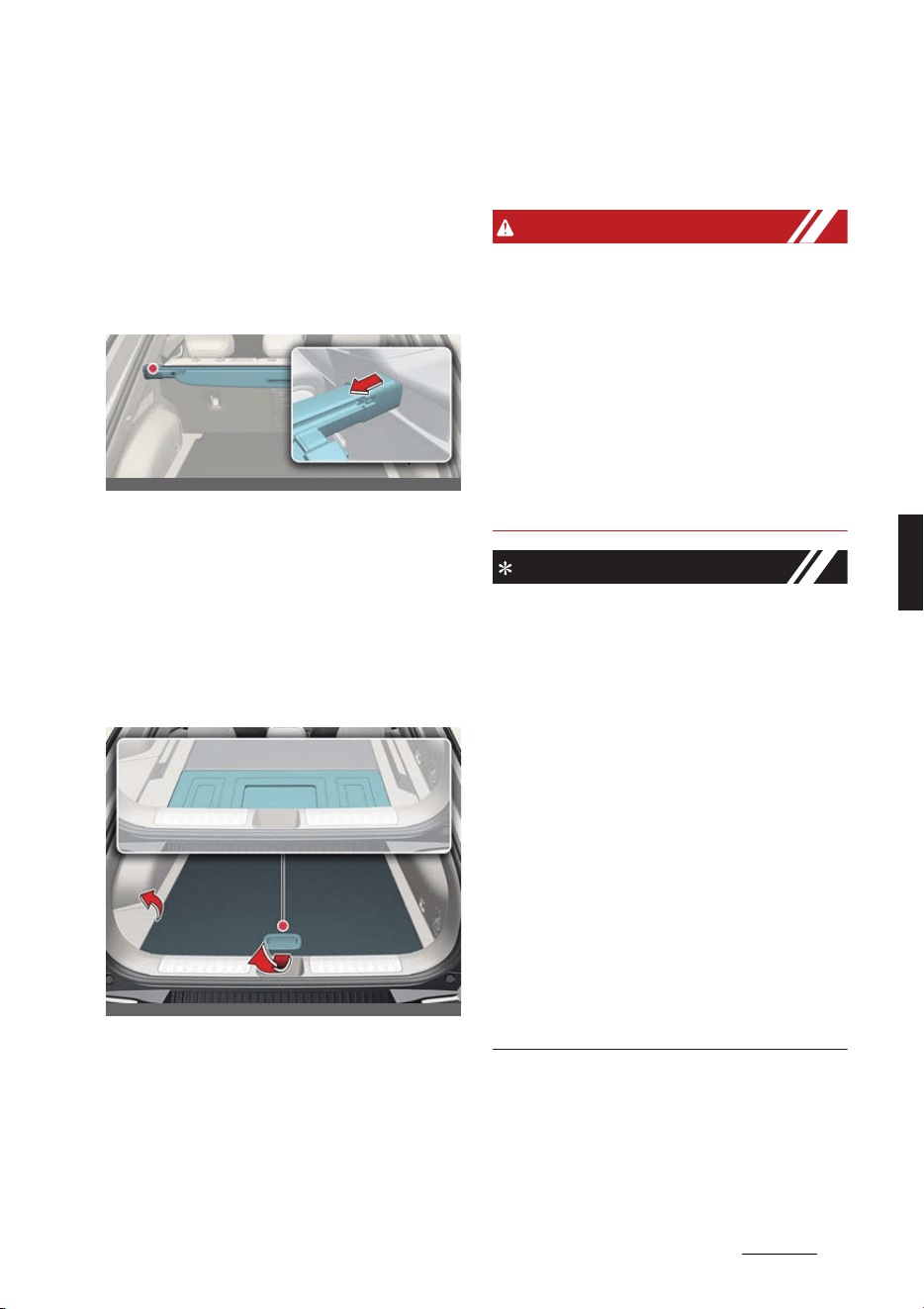
87
5
5
Features of your vehicle Storage compartment
Operation
1. Pull the cargo security screen towards
the rear of the vehicle by the handle
(1).
2. Insert the guide pin into the guide (2).
Removing the cargo security
screen
Operation
1. Push the guide pin in the direction.
2. Pull the cargo security screen out.
3. Open the luggage tray and keep the
cargo security screen in the tray.
Removing the cargo security
screen from luggage tray
Operation
1. Pull the luggage tray board up.
2. Push the guide pin into the center.
3. While pushing the guide pin, pull out
the cargo security screen.
4. The luggage side tray can be
removed to remove the cargo security
screen more easily.
WARNING
僅 Do not place objects on the cargo
security screen. Such objects may
move around inside the vehicle and
possibly injure vehicle occupants
during an accident or when braking.
僅 Never allow anyone to ride in the lug
-
gage compartment. It is designed for
luggage only.
僅 Maintain the balance of the vehicle
and locate the weight as forward as
possible.
NOTICE
僅 Since the cargo security screen may
be damaged or malformed, do not put
luggage on it when it is used.
僅 Pull out the cargo security screen
using the handle in the center to pre
-
vent the guide pin from falling out of
the guide.
僅 The cargo security screen may not
automatically slide back in if the cargo
security screen is not fully pulled out.
Fully pull it out and then let go.
僅 The cargo security screen and rear
seat may be damaged when the rear
seatback is reclined.
僅 Note that if you release the handle
while pulling the luggage screen han
-
dle all the way, the screen may wind
up quickly and be damaged.
OCV041073L
OCV041074L
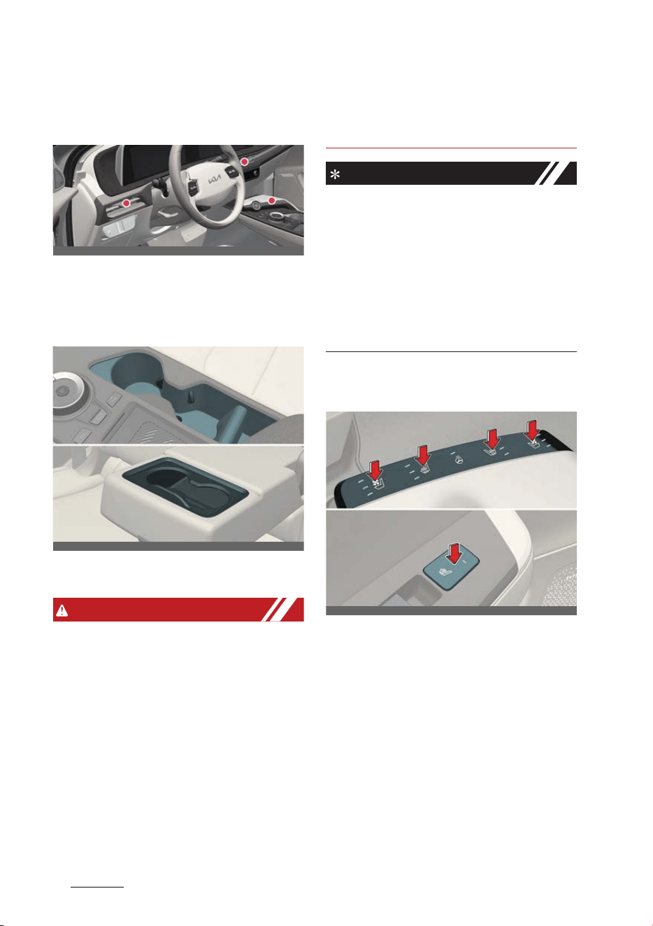
Features of your vehicle
885
Interior features
Interior features
Ambient lights (if equipped)
The ambient lights are installed in the
front crash pad, front doors, and the
top/bottom of the center console.
Cup holders
Cups or small drink cans can be placed
in the cup holders.
WARNING
僅 Do not place uncovered cups with hot
liquid in the cup holder while the vehi
-
cle is in motion. If the hot liquid spills,
you burn yourself. Such a burn to the
driver could lead to loss of control of
the vehicle.
僅 To reduce the risk of personal injury in
the event of sudden stop or collision,
do not place uncovered or unsecured
bottles, glasses, cans, etc., in the cup
holder while the vehicle is in motion.
僅 Keep cans or bottles out of direct sun
light and do not put them in a vehicle
that is heated up. It may explode.
NOTICE
僅 Keep your drinks sealed while driving
to prevent spilling your drink. If liquid
spills, it may get into the vehicle's
electrical/electronic system and dam
-
age electrical/electronic parts.
僅 When cleaning spilled liquids, do not
dry the cup holder at high tempera
-
ture. This may damage the cup
holder.
Seat warmer/ventilation (if
equipped)
The seat warmer/ventilation is provided
to warm/cool the front seats.
* The seat ventilation is provided only on
the front seats.
Operation
僅 Push either of the buttons to warm
the driver's seat or the front passen
-
ger's seat.
僅 It defaults to the OFF position when
the vehicle is in the ON position.
OCV041076K
OCV041077L_2
OCV041078L_2
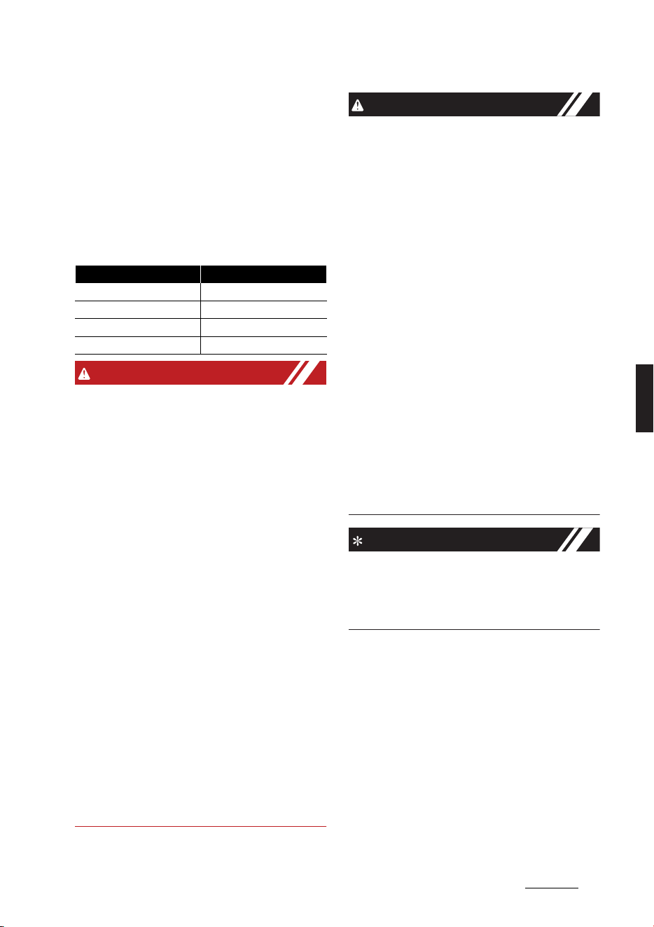
89
5
5
Features of your vehicle Interior features
僅 The seat warmer/ventilation automat
-
ically controls the seat temperature
depending on the ambient tempera
-
ture when the vehicle is running. For
more details, refer to "Auto. controls
that use climate control settings (if
equipped)" on page 5-84.
僅 The temperature setting of the seat
will change as follows:
WARNING
The seat warmers can cause a SERIOUS
BURN, even at low temperatures and
especially if used for long periods of
time. Passengers must be able to feel if
the seat is becoming too warm so they
can turn it off, if needed.
Seat warmers consumes huge amount
of electricity. Please avoid using seat
warmers while the vehicle is off in order
to prevent the battery discharge.
People who cannot detect temperature
change or pain to the skin should use
extreme caution, especially the following
types of passengers:
僅 Infants, children, elderly or handi
-
capped persons, or hospital outpa
-
tients
僅 Persons with sensitive skin or those
that burn easily
僅 Fatigued individuals
僅 Intoxicated individuals
僅 Individuals taking medication that can
cause drowsiness or sleepiness
(sleeping pills, cold tablets, etc.)
CAUTION
僅 When cleaning the seats, do not use
an organic solvent such as paint thin
-
ner, benzene, alcohol and gasoline.
Doing so may damage the surface of
the heater or seats.
僅 To prevent overheating the seat
warmer, do not place anything on the
seats that insulates against heat, such
as blankets, cushions or seat covers
while the seat warmer is in operation.
僅 Do not place heavy or sharp objects
on seats equipped with seat warmers.
Damage to the seat warming compo
-
nents could occur.
僅 Do not change the seat cover. It may
damage the seat warmer or air venti
-
lation system.
僅 When cleaning the seats, do not use
an organic solvent such as paint thin
-
ner, benzene, alcohol and gasoline.
Doing so may damage the air ventila
-
tion seat.
NOTICE
With the seat warmer buttons in the ON
position, the heating system in the seat
turns off or on automatically depending
on the seat temperature.
Temperature Duration
OFF -
High 30 minutes
Medium 60 minutes
Low -
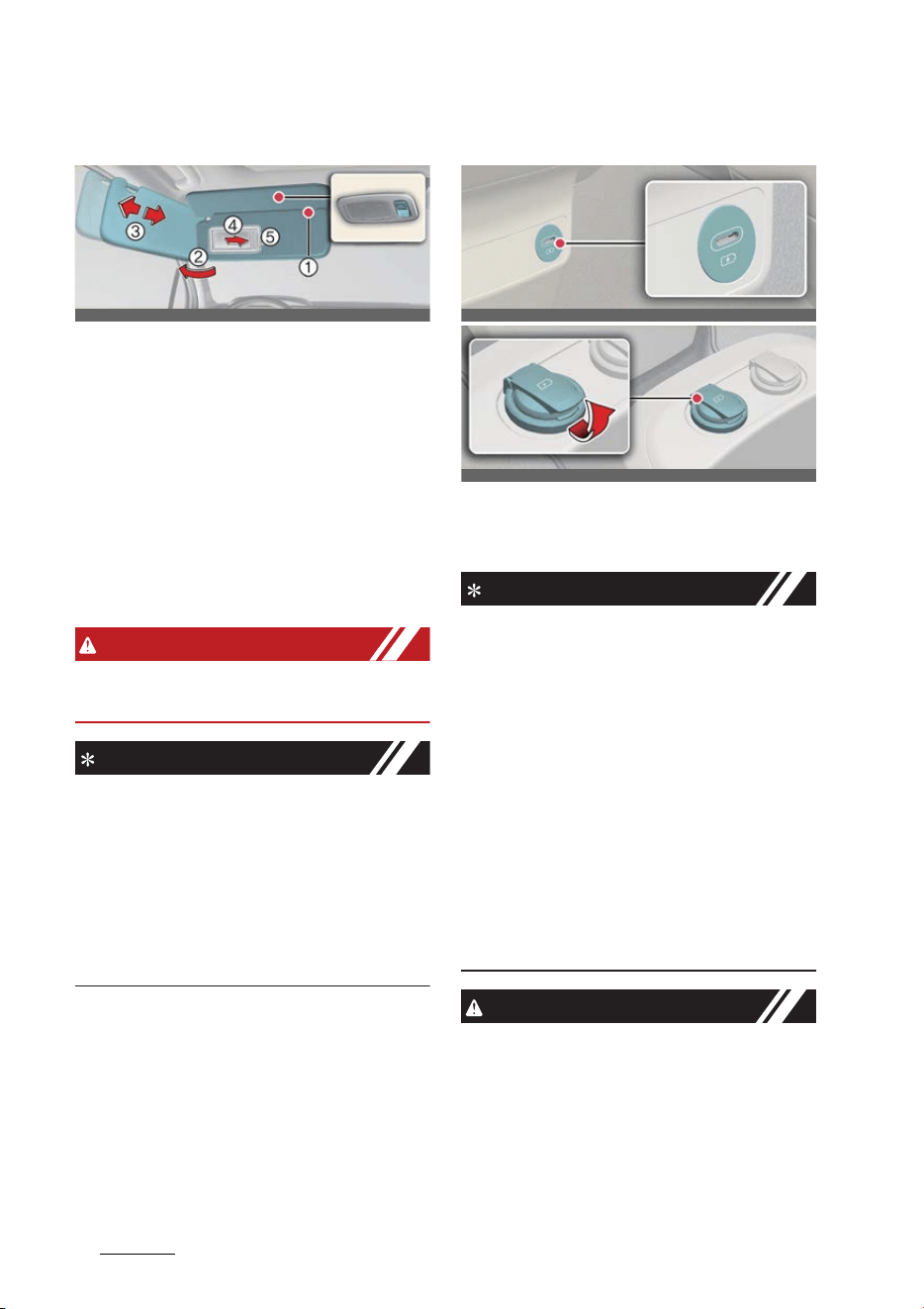
Features of your vehicle
905
Interior features
Sun visor
Operation
1. Pull down and unsnap it from the
bracket (1).
2. Swing it to the side (2).
僅 Slide the sun visor if necessary (3).
僅 Pull down and slide the mirror
cover (4) to use the vanity mirror.
僅 The ticket holder (5) is provided for
the purpose of holding a tollgate
ticket.
WARNING
For your safety, do not block your view
when using the sun visor.
NOTICE
僅 Do not put several tickets in the ticket
holder at one time. This could cause
damage to the ticket holder.
僅 Always have the switch in the off posi
-
tion when the vanity mirror lamp is
not in use. If the sun visor is closed
without the lamp off, it may discharge
the battery or damage the sun visor.
USB charger
The USB charger allows drivers and pas
-
sengers to charge their digital devices
such as smart phones and tablets.
INFORMATION
僅 Quick Charge 2.0 is available on the
smart phone or the table PC equipped
with fast charging capabilities. The
applicable is as follows: (https://
www.qualcomm.com/documents/
quickcharge-device-list) The smart
phone or PC tablet without fast
charging is charged at a regular
speed.
僅 Rated output
- Digital devices with fast charging:
9.0 V, 1.67 A
- Digital devices with normal
charging: 5.0 V, 2.1 A
CAUTION
僅 Use the USB car charger with the
vehicle on. Otherwise, Vehicle battery
can be discharged.
僅 Use the official USB cable of the man
-
ufacturer of the digital device to be
charged.
OCV041079L
OCV041080L
OCV041544L
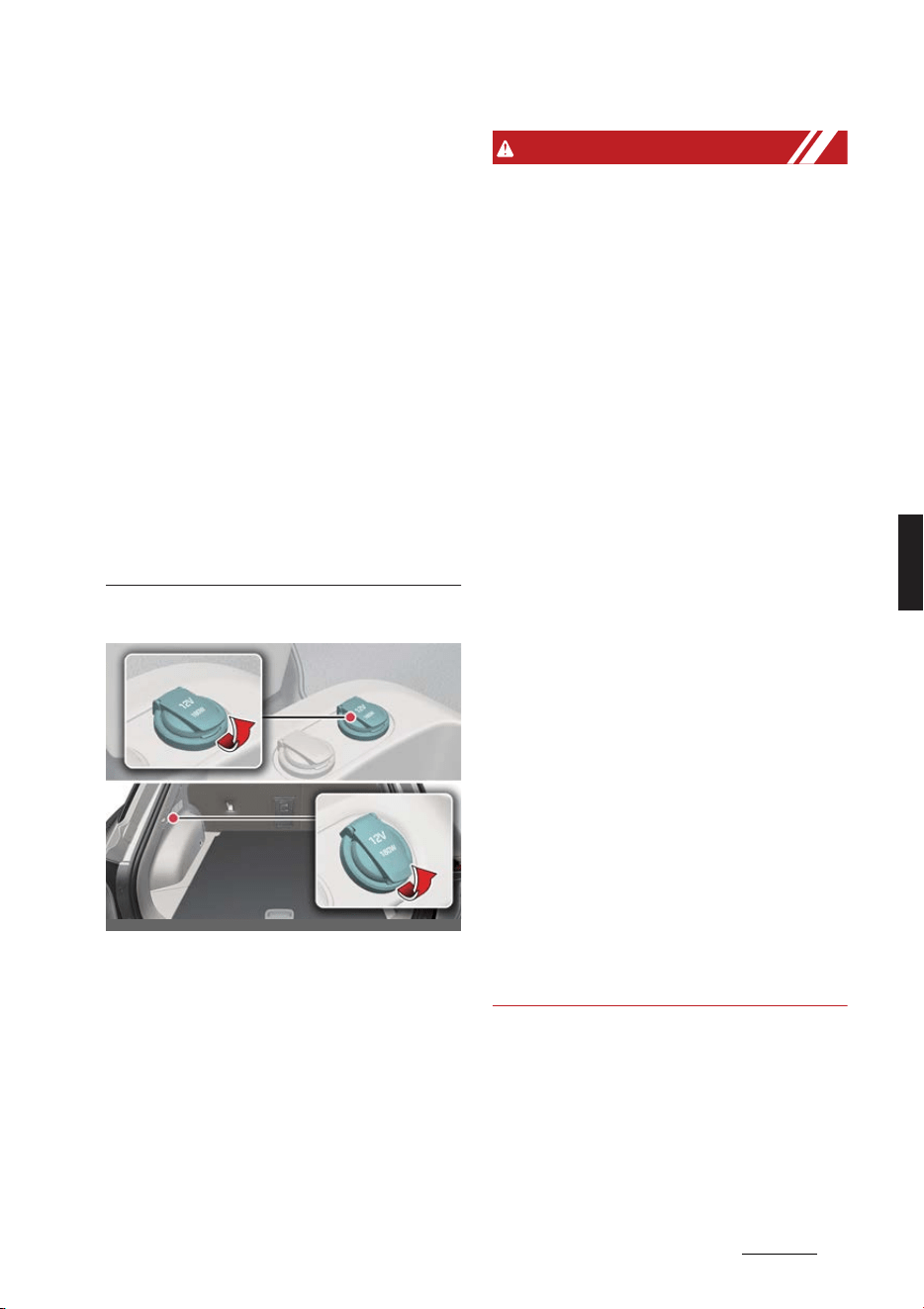
91
5
5
Features of your vehicle Interior features
僅 Make sure that any foreign object,
drinks, and water do not come into
contact with the USB car charger.
Water or foreign object can damage
the USB charger.
僅 Do not use the device those current
consumption exceeds 2.1 A.
僅Do not connect an electrical device
that generates excessive electromag
-
netic noise to the USB car port. If you
do so, noise can be caused or vehicle
electronic devices can be interrupted
while audio or AV is on.
僅 If the charger is connected incorrectly,
it can cause serious damage on the
devices. Please note that damages
due to incorrect usage are not cov
-
ered by warranty service.
Power outlet (if equipped)
The power outlet allows drivers and pas
-
sengers to charge their digital devices
such as smart phones and tablets.
Operating condition(s)
僅 The devices should draw less than 15
A when The vehicle is in the ON posi
-
tion.
WARNING
僅 Use the power outlet only when the
vehicle is on and remove the acces
-
sory plug after use. Using the acces
-
sory plug for prolonged periods of
time with the vehicle off could cause
the battery to discharge.
僅 Only use 12 V electric accessories
which are less than 15 A in electric
capacity.
僅Adjust the air-conditioner or heater to
the lowest operating level when using
the power outlet.
僅 Close the cover when not in use.
僅 Some electronic devices can cause
electronic interference when plugged
into a vehicle's power outlet. These
devices may cause excessive audio
static and malfunctions in other elec
-
tronic systems or devices used in your
vehicle.
僅 Push the plug in as far as it will go. If
good contact is not made, the plug
may overheat and the fuse may open.
僅 Plug in battery equipped electronic
devices with reverse current protec
-
tion. The current from the battery may
flow into the vehicle's electrical/elec
-
tronic system and cause system mal
-
function.
僅 Do not put a finger or a foreign object
(pen, etc.) into a power outlet and do
not touch with a wet hand. You may
get an electric shock.
OCV041081L_4
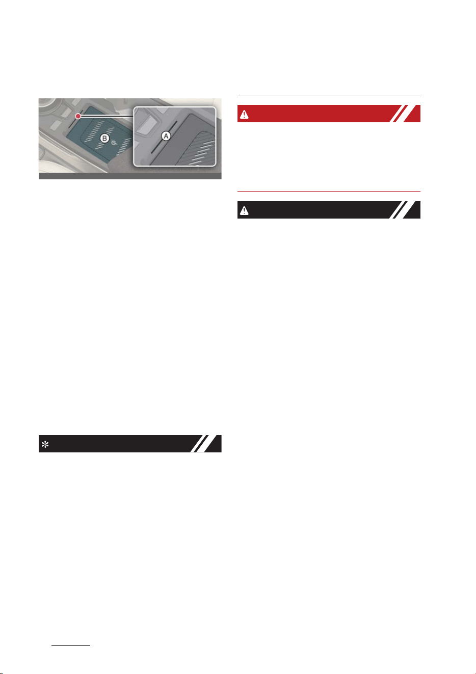
Features of your vehicle
925
Interior features
Wireless smartphone charging
system (if equipped)
A: Indicator
B: Charging pad
Operation
僅 Place the smartphone at the center of
the wireless charging pad.
僅 The indicator light will change to
orange once the wireless charging
begins. The light will change to green
when charging is complete.
僅 You can choose to turn the wireless
charging function ON or OFF through
the infotainment system.
Operating condition(s)
僅 The wireless charging system is
designed for one smart phone
equipped with Qi charging only.
INFORMATION
僅 If the wireless charging does not work,
gently move your smart phone
around the pad until the charging
indicator light turns orange. Depend
-
ing on the smart phone, the charging
indicator light may not turn green
even after the charging is complete.
僅 If the wireless charging is not func
-
tioning properly, the orange light will
blink and flash for ten seconds then
turn off. In such cases, remove the
smart phone from the pad and
replace it on the pad again, or double
check the charging status.
WARNING
If any metallic object such as coins is
located between the wireless charging
system and the smart phone, the
charging may be disrupted. Also, the
metallic object may heat up.
CAUTION
僅 When the interior temperature of the
wireless charging system rises above
a set temperature, the wireless
charging will cease to function. After
the interior temperature drops below
the threshold, the wireless charging
function will resume.
僅 If there is any metallic object between
the smart phone and the wireless
charging pad, immediately remove
the smart phone. Remove the metallic
object after it has completely cooled
down.
僅 The wireless charging may not func
-
tion properly when there is a heavy
accessory cover on the smart phone.
僅 The wireless charging will stop when
using the wireless smart key search
function to prevent radio wave disrup
-
tion.
僅 The wireless charging will stop when
the smart key is moved out of the
vehicle in ON position.
僅 The wireless charging will stop when
any of the doors is opened (applicable
for vehicles equipped with smart
keys).
僅 The wireless charging will stop when
the vehicle is turned OFF.
僅 The wireless charging will stop when
the smart phone is not in complete
OCV041311L

93
5
5
Features of your vehicle Interior features
contact with the wireless charging
pad.
僅 Items equipped with magnetic com
-
ponents such as credit card, tele
-
phone card, bankbook, any
transportation ticket and such may
become damaged during wireless
charging.
僅 Place the smart phone on the center
of the charge pad for best results. The
smart phone may not charge when
placed near the rim of the charging
pad. When the smart phone does get
charged, it may heat up excessively.
僅 For smart phones without built-in
wireless charging system, an appro
-
priate accessory has to be equipped.
僅 Smart phones of some manufacturers
may display messages on weak cur
-
rent. This is due to the particular char
-
acteristic of the smart phone and
does not imply a malfunction on wire
-
less charging function.
僅 The indicator light of some manufac
-
turers' smart phones may still be
orange after the smart phone is fully
charged. This is due to the particular
characteristic of the smart phone and
not a malfunction of the wireless
charging.
僅 When any smart phone without a
wireless charging function or a metal
-
lic object is placed on the charging
pad, a small noise may sound. This
small sound is due to the vehicle dis
-
cerning compatibility of the object
placed on the charging pad. It does
not affect your vehicle or the smart
phone in any way.
僅 The wireless cellular phone charging
system may not support certain cellu
-
lar phones, which are not verified for
the Qi specification ( ).
僅 For certain cellular phones with their
own protection, the wireless charging
speed may decrease and the wireless
charging may stop.
NOTICE
For some manufacturers' smart phones,
the system may not warn you even
though the smart phone is left on the
wireless charging unit. This is due to the
particular characteristic of the smart
phone and not a malfunction of the
wireless charging.
Coat hook
A coat hook is next to the left rear grab
handle.
WARNING
Do not hang other objects such as hang
-
ers or hard objects except clothes. Also,
do not put heavy, sharp or breakable
objects in the clothing's pockets. In an
accident or when the curtain air bag is
inflated, it may cause vehicle damage or
body injury.
CAUTION
Do not hang heavy clothes, since they
may damage the hook.
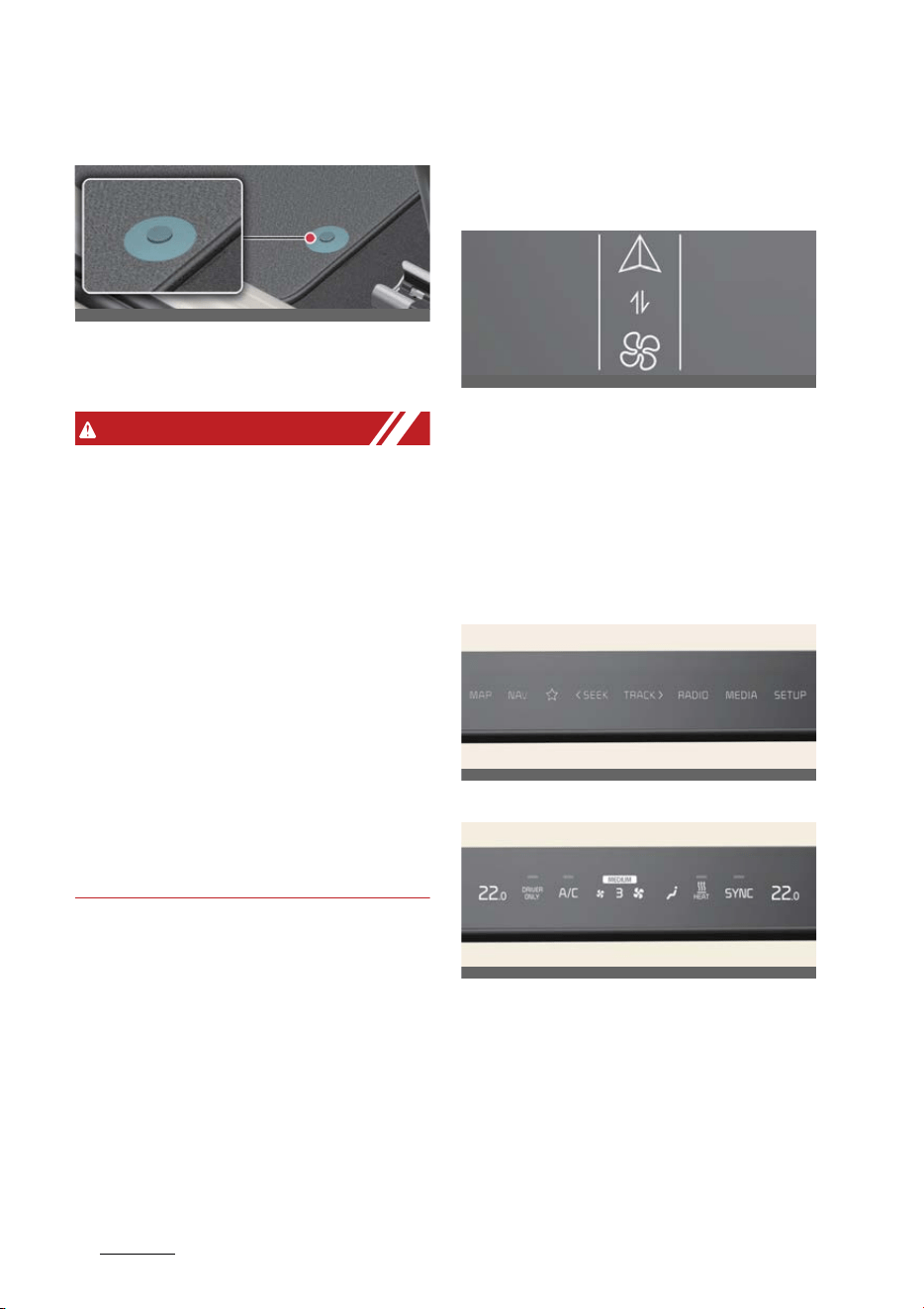
Features of your vehicle
945
Infotainment system
Floor mat anchors
Make sure the floor mat is attached to
the anchors to keep it from sliding for
-
ward.
WARNING
僅 Do not install after market floor mats
that are not capable of being securely
attached to the vehicle's floor mat
anchors. Unsecured floor mats can
interfere with pedal operation.
僅 Use floor mats not too thick and
designed to be properly secured on
the floor to avoid the interference with
pedals. Make sure that installing the
floor mats without removing plastic
films on carpets may damage or
break floor mat fix rings, resulting in
the mats to be unsecured. Especially
for a driver's seat, the unsecured mats
may cause unintended acceleration/
brake. Ensure to remove all the plastic
films on the carpets before installing
the mats.
Infotainment system
Using the infotainment/climate
switchable controller
Press the button on the switchable con
-
troller to switch between infotainment
system or climate control panel.
Press and hold the button to select the
default mode for the control panel.
Switching between panels
Infotainment control panel
Climate control panel
Press the button on the switchable con
-
troller to select the desired control panel.
The selected control panel icon will be
illuminated and the control panel will be
changed.
僅 The knob display will be illuminated
according to the selected control
panel mode.
OCV041082L
OCV041315
OCV041316
OCV041548L
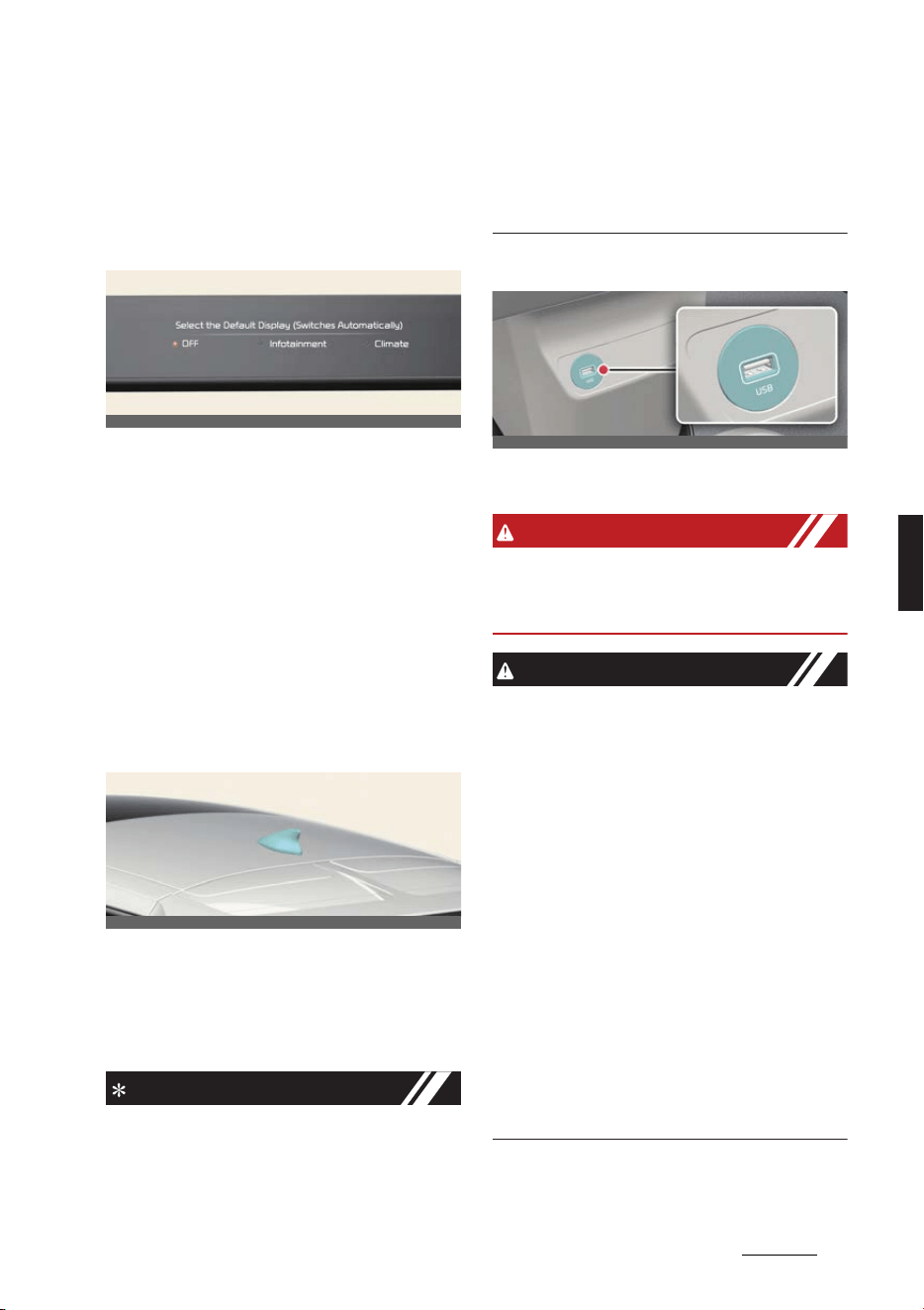
95
5
5
Features of your vehicle Infotainment system
僅 When the vehicle is in the ACC posi
-
tion, only the infotainment system will
be activated.
Setting the default mode
Press and hold the button to select the
default mode for the control panel.
僅 After the setting, the control panel will
return to the default mode after a cer
-
tain period of time even if the control
panel is switched to the different
mode.
僅 If the mode is set to 'OFF', the control
panel will display the mode used
recently.
Audio system
Sharkfin antenna
The roof antenna transmits and receives
wireless signals such as AM/FM, DAB,
GNSS, LTE etc.
* The signals which antenna can transmit
and receive vary by the vehicle option.
NOTICE
僅 If you install an aftermarket HID head
lamp, your vehicle's audio and elec
-
tronic device may malfunction.
僅 Avoid adding metallic coatings such
as Ni, Cd, etc. These can degrade the
receiving AM and FM broadcast sig
-
nals.
USB port
You can use an USB port to plug in the
USB.
WARNING
Do not use a cellular phone while driv
-
ing. Stop at a safe location to use a cellu
-
lar phone.
CAUTION
僅 Depending on the size, length, or
shape of the USB stick, the USB
device may be damaged or deformed.
When the stick is stuck, forcibly pull
-
ing the USB stick can cause damage
to the port. If the USB stick does not
fit, do not forcibly push the USB stick
to the port and try another USB stick
with different specifications.
僅 When using a communication system
such as a cellular phone or a radio set
inside the vehicle, a separate external
antenna must be fitted. When a cellu
-
lar phone or a radio set is used with
only the internal antenna, it may inter
-
fere with the vehicle's electrical sys
-
tem and adversely affect the safe
operation of the vehicle.
OCV041559L
OCV041083L
OCV041084L


6Driving your vehicle
Driv ing your vehicle
Before driving ................................................................................6-6
僅 Necessary vehicle inspections.................................................................... 6-6
僅 Good driving practices .................................................................................. 6-6
僅 Good braking practices................................................................................. 6-7
Vehicle power ................................................................................6-8
僅 Starting the vehicle..........................................................................................6-8
Reduction gear ............................................................................6-10
僅 Changing gear.................................................................................................6-10
僅 Shift-lock system.............................................................................................6-11
僅 LCD display messages................................................................................. 6-13
Regenerative braking system .................................................... 6-15
僅 Adjusting regenerative braking with paddle shifter....................... 6-15
僅 One pedal driving .......................................................................................... 6-15
僅 i-Pedal ................................................................................................................. 6-16
Smart regeneration system........................................................ 6-17
僅 Operating smart regeneration system................................................. 6-17
僅 Smart regeneration system malfunction and limitations.............6-18
Brake system................................................................................6-22
僅 In the event of brake failure......................................................................6-22
僅 Brake disc cleaning .......................................................................................6-22
僅 Parking brake ..................................................................................................6-24
僅 AUTO HOLD .....................................................................................................6-28
Vehicle safety system .................................................................6-29
僅 Anti-lock Brake System (ABS) ..................................................................6-29
僅 Electronic Stability Control (ESC) ............................................................6-29
僅 Hill-start Assist Control (HAC) ................................................................. 6-30
僅 Multi-Collision Brake (MCB) ...................................................................... 6-31
僅 Vehicle Stability Management (VSM).................................................... 6-31
僅 Emergency Stop Signal (ESS) ...................................................................6-32
僅 Brake Assist System (BAS).........................................................................6-32

6 Driving your vehicle
Electronic Limited Slip Differential (For GT)........................... 6-33
Electronic Control Suspension .................................................. 6-34
Drive mode integrated control system .................................... 6-35
僅 DRIVE MODE....................................................................................................6-35
僅 DRIVE MODE characteristics for 4WD..................................................6-36
Drift Mode (For GT).....................................................................6-37
Maximum Power Output Mode (For GT)................................. 6-38
All wheel drive (4WD) ................................................................ 6-39
僅 For safe 4WD operation..............................................................................6-39
僅 Emergency precautions .............................................................................. 6-41
Active air flap .............................................................................. 6-42
僅 Active air flap malfunction.........................................................................6-42
Forward Collision-Avoidance Assist (FCA) ............................. 6-43
僅 Forward Collision-Avoidance Assist settings.....................................6-46
僅 Forward Collision-Avoidance Assist operation ................................ 6-48
僅 Forward Collision-Avoidance Assist malfunction and
limitations...........................................................................................................6-55
Lane Keeping Assist (LKA) ........................................................ 6-62
僅 Lane Keeping Assist settings ....................................................................6-62
僅 Lane Keeping Assist operation ................................................................6-64
僅 Lane Keeping Assist malfunction and limitations............................6-65
Blind-Spot Collision-Avoidance Assist (BCA) ......................... 6-67
僅 Blind-Spot Collision-Avoidance Assist settings.................................6-69
僅 Blind-Spot Collision-Avoidance Assist operation............................ 6-70
僅 Blind-Spot Collision-Avoidance Assist malfunction and
limitations...........................................................................................................6-73
Safe Exit Warning (SEW) ............................................................6-77
僅 Safe Exit Warning (SEW) settings ...........................................................6-78
僅 Safe Exit Warning operation .....................................................................6-78
僅 Safe Exit Warning malfunction and limitations ................................6-79

6Driving your vehicle
Safe Exit Assist (SEA)..................................................................6-81
僅 Safe Exit Assist settings...............................................................................6-82
僅 Safe Exit Assist operation...........................................................................6-83
僅 Safe Exit Assist malfunction and limitations..................................... 6-84
Manual Speed Limit Assist (MSLA) .......................................... 6-86
僅 Manual Speed Limit Assist operation................................................... 6-86
Intelligent Speed Limit Assist (ISLA)........................................ 6-88
僅 Intelligent Speed Limit Assist settings.................................................. 6-89
僅 Intelligent Speed Limit Assist operation..............................................6-90
僅 Intelligent Speed Limit Assist malfunction and limitations..........6-92
Driver Attention Warning (DAW) ............................................. 6-94
僅 Driver Attention Warning settings ..........................................................6-95
僅 Driver Attention Warning operation ......................................................6-96
僅 Driver Attention Warning malfunction and limitations................. 6-98
Blind-Spot View Monitor (BVM) ............................................. 6-100
僅 Blind-Spot View Monitor settings ........................................................6-100
僅 Blind-Spot View Monitor operation.....................................................6-100
僅 Blind-Spot View Monitor malfunction................................................6-100
Cruise Control (CC) ................................................................... 6-101
僅 Cruise Control operation...........................................................................6-101
Smart Cruise Control (SCC)..................................................... 6-104
僅 Smart Cruise Control settings................................................................ 6-105
僅 Smart Cruise Control operation............................................................ 6-108
僅 Smart Cruise Control display and control........................................ 6-109
僅 Smart Cruise Control malfunction and limitations........................ 6-114
Navigation-based Smart Cruise Control (NSCC)................... 6-118
僅 Navigation-based Smart Cruise Control settings .......................... 6-118
僅 Navigation-based Smart Cruise Control operation....................... 6-119
僅 Navigation-based Smart Cruise Control limitations.................... 6-120
Lane Following Assist (LFA)..................................................... 6-123

6 Driving your vehicle
僅 Lane Following Assist settings ...............................................................6-123
僅 Lane Following Assist operation............................................................6-124
僅 Lane Following Assist malfunction and limitations.......................6-126
Highway Driving Assist (HDA).................................................6-126
僅 Highway Driving Assist settings............................................................ 6-127
僅 Highway Driving Assist operation ........................................................6-128
僅 Highway Driving Assist malfunction and limitations....................6-134
Rear View Monitor (RVM).........................................................6-136
僅 Rear View Monitor settings .....................................................................6-136
僅 Rear View Monitor operation..................................................................6-136
僅 Rear View Monitor malfunction and limitations.............................6-137
Surround View Monitor (SVM).................................................6-138
僅 Surround View Monitor settings............................................................6-139
僅 Surround View Monitor operation....................................................... 6-140
僅 Surround View Monitor malfunction and limitations................... 6-141
Rear Cross-Traffic Collision-Avoidance Assist (RCCA) ........6-142
僅 Rear Cross-Traffic Collision-Avoidance Assist settings ..............6-143
僅 Rear Cross-Traffic Collision-Avoidance Assist operation.......... 6-144
僅 Rear Cross-Traffic Collision-Avoidance Assist malfunction
and limitations ...............................................................................................6-147
Reverse Parking Distance Warning (PDW) ........................... 6-150
僅 Reverse Parking Distance Warning settings.....................................6-151
僅 Reverse Parking Distance Warning operation.................................6-151
僅 Reverse Parking Distance Warning malfunction and
precautions......................................................................................................6-152
Forward/Reverse Parking Distance Warning (PDW)............6-154
僅 Forward/Reverse Parking Distance Warning settings.................6-154
僅 Forward/Reverse Parking Distance Warning operation.............6-155
僅 Forward/Reverse Parking Distance Warning malfunction and pre-
cautions.............................................................................................................6-157
Reverse Parking Collision-Avoidance Assist (PCA) ............. 6-159

6Driving your vehicle
僅 Reverse Parking Collision- Avoidance Assist settings .................6-159
僅 Reverse Parking Collision- Avoidance Assist operation ............. 6-161
僅 Reverse Parking Collision- Avoidance Assist malfunction and lim-
itations ...............................................................................................................6-162
Remote Smart Parking Assist (RSPA).....................................6-166
僅 Remote Smart Parking Assist settings .............................................. 6-168
僅 Remote Smart Parking Assist operation............................................6-169
僅 Remote Smart Parking Assist malfunction and limitations.......6-183
Declaration of conformity ........................................................6-187
Special driving conditions ........................................................6-194
Winter driving ............................................................................6-198
Trailer towing.............................................................................6-201
僅 Hitches.............................................................................................................6-202
僅 Safety chains.................................................................................................6-202
僅 Trailer brakes................................................................................................6-202
僅 Driving with a trailer...................................................................................6-202
僅 Maintenance when towing a trailer ....................................................6-205
僅 If you do decide to tow a trailer............................................................6-205
Vehicle weight .......................................................................... 6-207
僅 Base curb weight.........................................................................................6-207
僅 Vehicle curb weight....................................................................................6-207
僅 Cargo weight.................................................................................................6-207
僅 GAW (Gross axle weight).........................................................................6-207
僅 GAWR (Gross axle weight rating) ........................................................6-207
僅 GVW (Gross vehicle weight)...................................................................6-207
僅 GVWR (Gross vehicle weight rating) ..................................................6-207
僅 Overloading...................................................................................................6-207
僅 Loading Your Vehicle ................................................................................6-208

Driving your vehicle
66
Before driving
Driving your vehicle
Before driving
Necessary vehicle inspections
Be sure to check the following fluid lev
-
els on a regular basis at the exact inter
-
val:
僅 Brake fluid
僅 Washer fluid
For more details, refer to "Maintenance"
on page 8-3.
WARNING
Focus on the road while driving. The
driver's primary responsibility is in the
safe and legal operation of the vehicle.
Use of any handheld devices, other
equipment or vehicle systems that dis
-
tract the driver should not be used
during vehicle operation.
Before entering vehicle
僅Be sure that all windows, outside mir
-
rors, and outside lights are clean.
僅 Check the condition of the tires.
僅 Check under the vehicle for any sign
of leaks.
僅 Make sure there are no obstacles
behind you if you intend to back up.
Before starting the vehicle
僅 Close and lock all doors.
僅 Position the seat so that all controls
are easily reached.
僅 Buckle your seat belt.
僅 Adjust both inside and outside rear
view mirrors.
僅Be sure that all lights work.
僅 Check all gauges.
僅 Check the operation of warning lights
when the vehicle is in the ON position.
僅 Release the parking brake and make
sure the brake warning light is off.
WARNING
僅 Always check the surrounding areas
near your vehicle for people, espe
-
cially children, before putting a vehi
-
cle into D (Drive) or R (Reverse).
僅 Securely store items in your vehicle.
When you make a sudden stop or turn
the steering wheel rapidly, loose
objects may drop on the floor and it
could interfere with the operation of
the foot pedals, possibly causing an
accident.
僅 Do not drive while under the influence
of alcohol, drugs, or other impairing
substances. Drinking and driving is
dangerous. Even a small amount of
alcohol will affect your reflexes, per
-
ceptions and judgment.
Driving while under the influence of
drugs or other impairing substances is
as dangerous as or more dangerous
than driving drunk.
僅 Always wear appropriate shoes when
operating your vehicle. Unsuitable
shoes (high heels, ski boots, sandals,
etc.) may interfere with your ability to
use the brake and accelerator pedals.
Good driving practices
僅 Never shift from P or N to any other
position with the accelerator pedal
pressed.
僅 Never shift to P when the vehicle is
moving.
僅 Stop the vehicle completely before
shifting to R or D.
僅 Never change the gear to N and coast
down the hill. This is extremely haz
-
ardous. Always make sure that the
vehicle is in R or D when it is moving.

7
6
6
Driving your vehicle Before driving
僅 Always use the parking brake. Do not
depend on P to keep the vehicle from
moving.
僅 Exercise extreme caution when driv
-
ing on a slippery surface. Be espe
-
cially careful when braking,
accelerating, or shifting gears. The
vehicle speed can change abruptly,
causing the tires to lose traction and
the vehicle to lose control.
WARNING
僅 If your vehicle becomes stuck in snow,
mud, sand, etc., then you may
attempt to rock the vehicle free by
moving it forward and backward. Do
not attempt this procedure if people
or objects are anywhere near the
vehicle. During the rocking operation
the vehicle may suddenly move for
-
ward or backward as it becomes
unstuck, causing injury or damage to
nearby people or objects.
僅 When driving uphill or downhill,
always shift to D (Drive) for driving
forward or shift to R (Reverse) for
driving backwards, and check the
gear position indicated on the cluster
before driving. Driving in the opposite
direction of the selected gear can lead
to a dangerous situation by shutting
off the vehicle and affecting the brak
-
ing performance.
僅 ALWAYS wear your seat belt. In a colli
-
sion, an unbelted occupant is signifi
-
cantly more likely to be seriously
injured or killed than a properly belted
occupant.
僅 Avoid high speeds when cornering or
turning.
僅 Do not make quick steering wheel
movements, such as sharp lane
changes or fast, sharp turns.
僅 The risk of a rollover is greatly
increased if you lose control of your
vehicle at highway speeds.
僅 Losing control often occurs if two or
more wheels drop off the roadway
and the driver oversteers to reenter
the roadway.
僅 In the event your vehicle leaves the
roadway, do not steer sharply.
Instead, slow down before pulling
back into the travel lanes.
僅 Never exceed posted speed limits.
Good braking practices
僅 Be sure the parking brake is not
engaged and the parking brake indi
-
cator light is off before driving.
僅 The vehicle will not stop as quickly if
the brakes are wet. Apply the brakes
lightly until the braking action returns
to normal.
僅 If you get a flat tire while driving,
apply the brakes gently and keep the
vehicle straight ahead while it slows
down. Pull the vehicle slowly and
safely off the road and stop in a safe
place.
僅 Be cautious when parking on a hill.
Firmly engage the parking brake and
shift to P.
僅 If your vehicle is facing downhill, turn
the front wheels into the curb to help
keep the vehicle from rolling.
If your vehicle is facing uphill, turn the
front wheels away from the curb to
help keep the vehicle from rolling.
僅 Block the wheels if there is no curb or
if it is required by other conditions to
keep the vehicle from rolling.
僅 The parking brake can freeze in the
engaged position under certain condi
-
tions such as snow or ice around or

Driving your vehicle
86
Vehicle power
near the rear brakes or if the brakes
are wet.
If there is risk of the parking brake
freezing, apply it only temporarily
while shifting to P and block the rear
wheels so that the vehicle cannot roll.
Then, release the parking brake.
僅 Do not hold the vehicle on an incline
with the accelerator pedal. This can
cause the reduction gear to overheat.
Always use the brake pedal or parking
brake.
僅 Do not pump the brake pedal as the
vehicle is equipped with ABS.
僅 The vehicle is equipped with elec
-
tronic hydraulic brake. Due to mal
-
function or power instability, the
brake booster may not operate nor
-
mally and cause the brake pedal to
feel stiff, resulting in longer braking
distances. In this case, stop the vehicle
by depressing the brake pedal stron
-
ger than usual. Have the system
inspected by a professional workshop.
Kia recommends visiting an autho
-
rized Kia dealer/service partner.
僅 The sound of electronic hydraulic
brake operating or its motor may be
heard temporarily when:
- Repeatedly depressing the brake
pedal
- Opening driver's door
Vehicle power
Starting the vehicle
Power button
Operation
僅OFF
- Press the EV button in P to turn the
vehicle off.
僅 ACC (Accessory)
- Press the EV button once without
depressing the brake pedal.
- The steering wheel is unlocked.
- The electrical accessories can be
operated.
- Turns off automatically after
approximately 1 hour to prevent
battery discharge.
僅ON
- Press the EV button twice without
depressing the brake pedal.
- The warning lights can be checked.
僅START/RUN
- Press the EV button while depress
-
ing the brake pedal in P (Park).
Vehicles equipped with an anti-
theft steering column lock
The steering wheel is locked when:
僅 The vehicle is in the OFF position
僅 The doors are opened
OCV051001L

9
6
6
Driving your vehicle Vehicle power
Starting the vehicle with smart
key
The vehicle will check for the smart key
when:
僅 The vehicle doors are opened
僅 The EV button is pressed
If the smart key is not in the vehicle, the
indicator ( ) and the message will
appear on the instrument cluster.
WARNING
僅 Never press the EV button while the
vehicle is in motion. This would result
in loss of directional control and brak
-
ing function, which could cause an
accident.
僅 Before leaving the driver's seat,
always make sure the gear is shifted
to P (Park) position, set the parking
brake fully and shut the vehicle off.
Unexpected and sudden vehicle
movement may occur if these precau
-
tions are not taken.
僅 Never reach for the EV button or any
other controls through the steering
wheel while the vehicle is in motion.
The presence of your hand or arm in
the area could cause loss of vehicle
control, an accident and serious
bodily injury or death.
僅 Do not place any movable objects
around the driver's seat as they may
move while driving, interfere with the
driver and lead to an accident.
僅 The vehicle will start, only when the
smart key is in the vehicle. Never
allow children or any person who is
unfamiliar with the vehicle touch the
EV button or related parts. Pushing
the EV button while the smart key is in
the vehicle may result in unintended
vehicle activation and/or unintended
vehicle movement.
CAUTION
僅 In an emergency situation while the
vehicle is in motion, you are able to
turn the vehicle off and to the ACC
position by pressing the EV button for
more than 2 seconds or 3 times
repeatedly within 3 seconds. If the
vehicle is still moving, to restart the
vehicle:
- Press the EV button when vehicle
speed is over approximately 5 km/h
(3 mph).
僅 If the vehicle is turned off while the
vehicle is in motion, do not attempt to
move the gear to the P (Park) position.
If the traffic and road conditions per
-
mit, you may put the gear in the N
(Neutral) position while the vehicle is
still moving and press the EV button
in an attempt to restart the vehicle.
僅 Do not press the EV button for more
than 10 seconds except when the stop
lamp fuse is blown.
NOTICE
僅 If you leave the EV button in the ACC
or ON position for a long time, the
battery will discharge.
僅 If you press the EV button without
pressing the brake pedal, the vehicle
will not start and the EV button
changes as follow:
- OFF → ACC → ON → OFF or ACC
僅 If the steering wheel doesn't unlock
properly, the EV button will not work.
Press the EV button while turning the
steering wheel right and left to release
the tension.
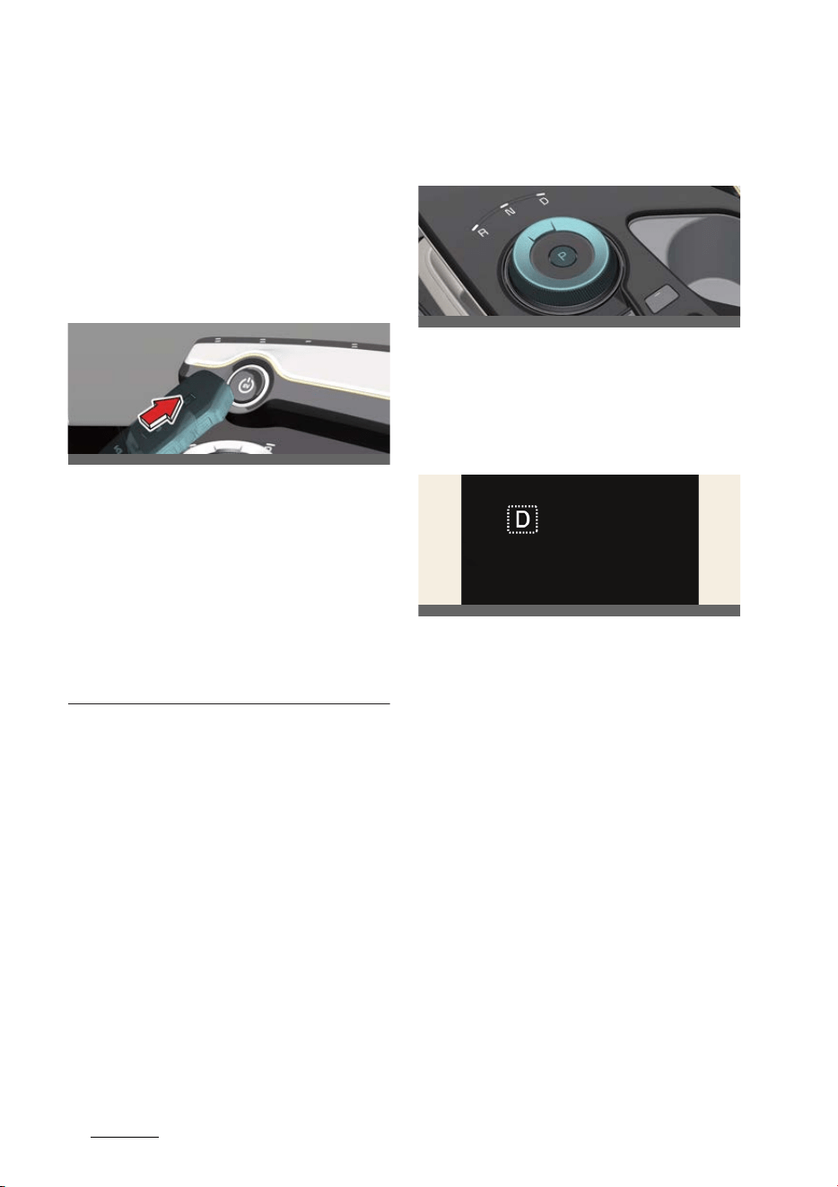
Driving your vehicle
106
Reduction gear
僅 You are able to turn off the vehicle
only when the vehicle is not in motion.
僅 If the battery is weak or the smart key
does not work correctly, you can start
the vehicle by pressing the EV button
with the smart key. When you press
the EV button directly with the smart
key, the smart key should contact the
button at a right angle.
僅 When the stop lamp fuse is blown,
you cannot start the vehicle normally.
Replace the fuse with a new one. If it
is not possible, you can start the vehi
-
cle by pressing the EV button for 10
seconds while it is in the ACC position.
The vehicle can start without pressing
the brake pedal. But for your safety
always press the brake pedal before
starting the vehicle.
Reduction gear
Changing gear
Operation
僅 Turn the shift dial.
僅 Press P button to shift to P (Park).
Gear position
The indicator in the instrument cluster
displays the gear position when the EV
button is in ON position.
Automatic shift to P (Park)
Operating condition(s)
僅 The driver door is opened in R
(Reverse), N (Neutral), D (Drive) while
vehicle is in ON position.
僅 The vehicle is in OFF position while
the gear is in R (Reverse), N (Neutral),
D (Drive).
Non-operating condition(s)
僅 When the vehicle is above certain
speed
OCV051002L
OCV051003L
OCV051104L
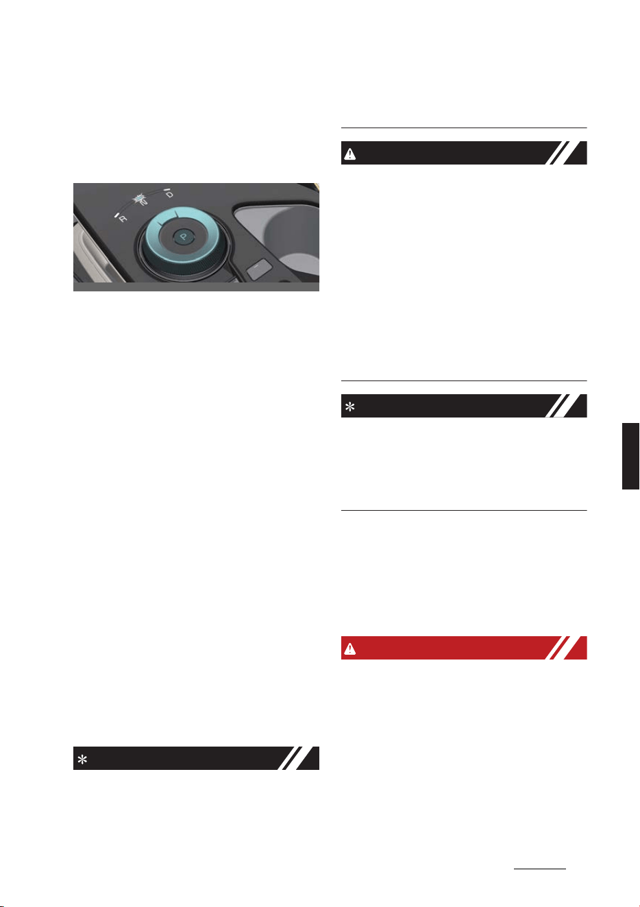
11
6
6
Driving your vehicle Reduction gear
N (Neutral) in vehicle ON/ACC
position
If you want to stay in N (Neutral) when
the vehicle is the ACC or ON state, do
the following.
Operation
1. Deactivate AUTO HOLD and release
the parking brake when the vehicle is
in ON position.
2. Depress the brake pedal.
3. Turn the shift dial to N (Neutral).
4. Take your foot off the brake pedal,
and the message will appear on the
instrument cluster.
5. Press and hold the OK button on the
steering wheel for more than 1 sec
-
ond.
If the Electronic Parking Brake is
applied, release the Electronic Parking
Brake manually while depressing the
brake pedal.
If equipped with Electronic Parking
Brake, it is not released automatically
when you turn the shift dial to N (Neu
-
tral).
6. Press the EV button after the mes
-
sage appears on the instrument clus
-
ter. The vehicle stays in N (Neutral)
after turning off the vehicle.
INFORMATION
However, if you open the driver's door
within 3 minutes in ACC position, the
gear will automatically shift to P (Park)
and the vehicle will change to OFF posi
-
tion.
CAUTION
Do not open the driver's door when
going through an automatic car wash
tunnel machine. Failure to follow this
instruction can damage your vehicle or
the car wash machine.
If the driver's door is opened within 3
minutes after shifting to N (Neutral),
your vehicle will automatically shift the
gear to P (Park).
For vehicles equipped with Electronic
Parking Brake (EPB), the parking brake
is automatically applied.
NOTICE
With the gear in N (Neutral), the vehicle
will be in the ACC position. Note that the
doors cannot be locked in ACC position
or the battery (12V) may discharge if left
in the ACC position for a long period.
Shift-lock system
Shift-lock system prevents shifting the
gear from P (Park) into N (Neutral)/R
(Reverse)/D (Drive) or N (Neutral) into R
(Reverse)/D (Drive) unless the brake
pedal is depressed.
WARNING
僅 ALWAYS check the surrounding areas
near your vehicle for people, espe
-
cially children, before shifting a vehi
-
cle into D (Drive) or R (Reverse).
僅 Before leaving the driver's seat,
always make sure the gear is in the P
(Park) position, then set the parking
brake, and place the Power button in
the OFF position. Unexpected and
OCV051003

Driving your vehicle
126
Reduction gear
sudden vehicle movement can occur
if these precautions are not followed.
僅 Shifting into P (Park) while the vehicle
is in motion may cause you to lose
control of the vehicle.
僅 After the vehicle has stopped, always
make sure P (Park) gear position is
selected, apply the parking brake, and
turn the vehicle off.
僅 Do not use the P (Park) position in
place of the parking brake.
僅 When you park the vehicle, make sure
Electronic Parking Brake is applied
even though the gear is in the P (Park)
position.
僅 If equipped with Electronic Parking
Brake, parking brake is applied auto
-
matically when the gear is shifted to P
(Park).
CAUTION
Always come to a complete stop before
shifting into or out of R (Reverse); you
may damage the reduction gear if you
shift into R (Reverse) while the vehicle is
in motion, except on "Rocking the vehi
-
cle" (refer to "Rocking the vehicle" on
page 6-195).
NOTICE
僅 Always depress the brake pedal while
shifting to another gear.
僅 You cannot shift the gear while the
charging cable is connected.
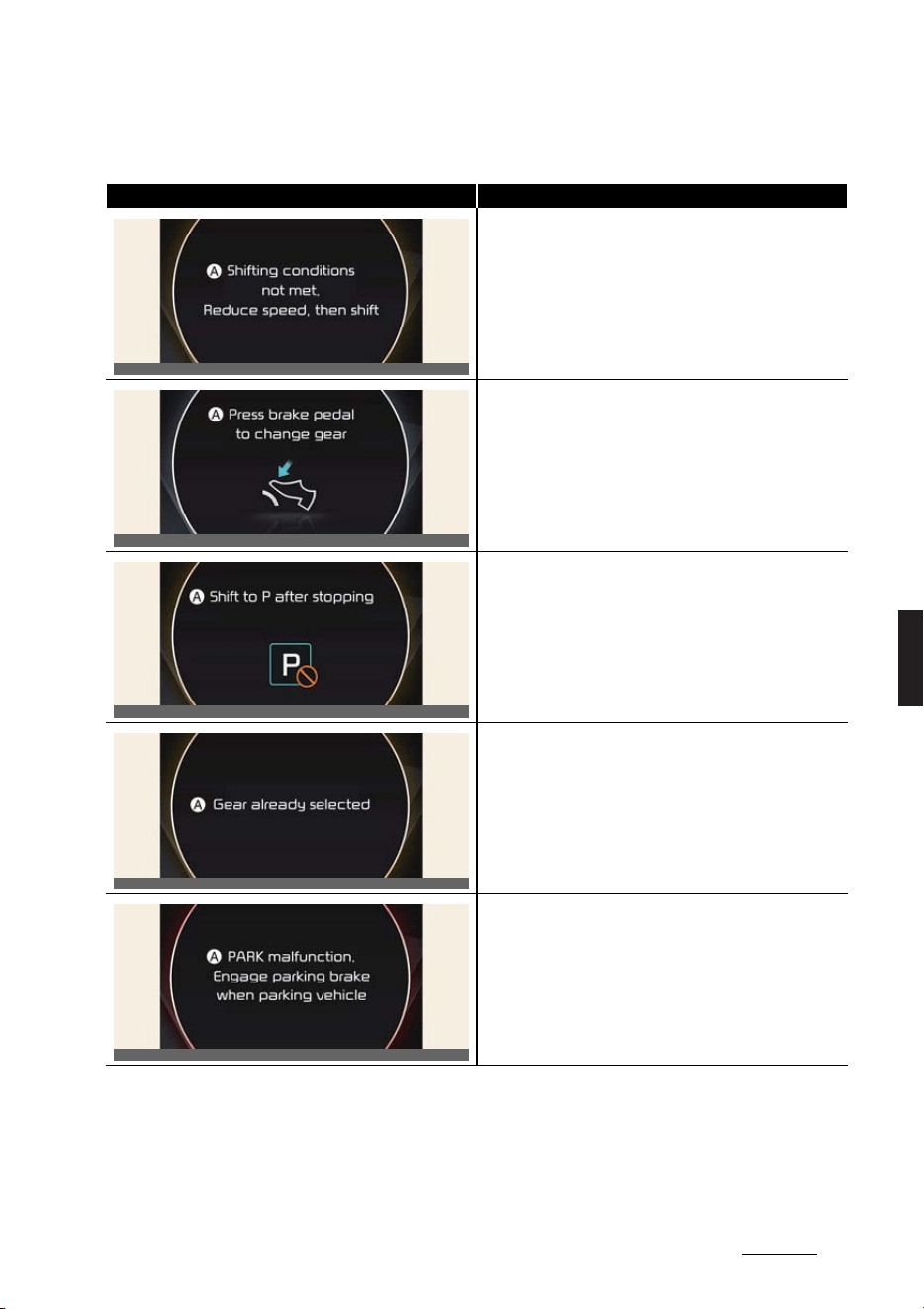
13
6
6
Driving your vehicle Reduction gear
LCD display messages
Message Content
A:
Shifting conditions not met. Reduce speed, then shift
僅 When driving speed is too fast to shift the gear.
僅 When the gear is shifted while the vehicle is in Utility mode.
A:
Press brake pedal to change gear
僅 When the brake pedal is not depressed while shifting the
gear.
A:
Shift to P after stopping
僅 When the gear is shifted to P (Park) while the vehicle is mov
-
ing.
A:
Gear already selected
僅 When the selected gear button is pressed again.
A:
PARK malfunction. Engage parking brake when parking
vehicle
僅 When there is a problem with function engaging P (Park)
position.
OCV051105L
OCV051106L
OCV051107L
OCV051108L
OCV051109L

Driving your vehicle
146
Reduction gear
A:
Check P button
僅 When there is problem with the P button.
A:
Check shifter dial
僅 When there is problem with the shift dial.
A:
Rotary shifter stuck
僅 When the shifter dial is continuously stuck or there is problem
with the shifter dial.
A:
Shift button held down
僅 When the shift button is stuck.
Message Content
OCV051110L
OCV051111L
OCV051112L
OCV051228L
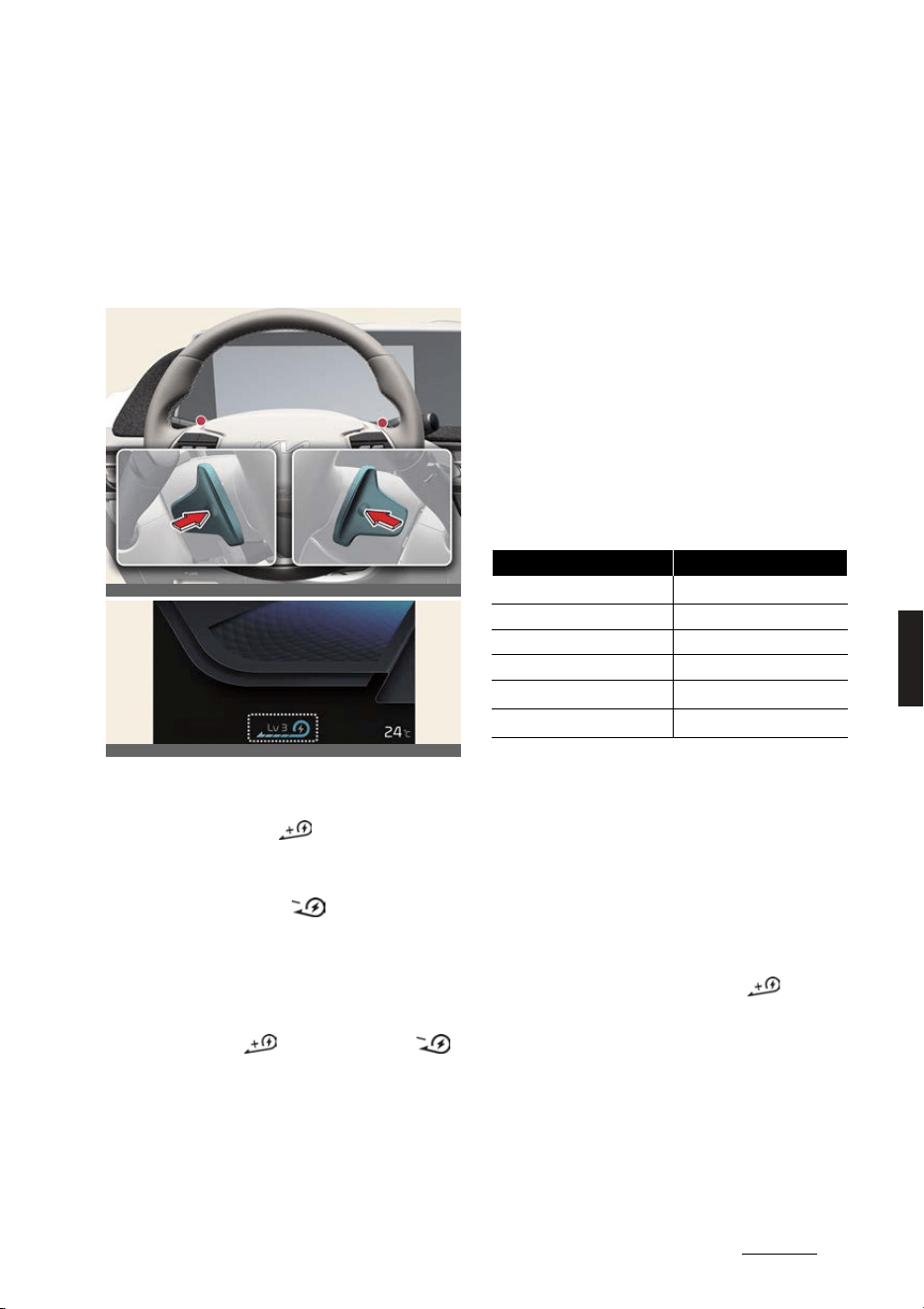
15
6
6
Driving your vehicle Regenerative braking system
Regenerative braking system
The regenerative braking system allows
you to charge the battery when you use
the brakes to stop the vehicle.
Adjusting regenerative braking
with paddle shifter
Operation
僅 Pull the left side ( ) of the paddle
shifter to increase regenerative brak
-
ing and deceleration.
僅 Pull the right side ( ) of the paddle
shifter to decrease regenerative brak
-
ing and deceleration.
Non-operating condition(s)
僅 The left side ( ) and right side ( )
of paddle shifters are pulled simulta
-
neously.
僅 Decelerating the vehicle by depress
-
ing the brake pedal.
僅 Cruise Control or Smart Cruise Con
-
trol is operating.
僅 The regenerative braking system is
activated in 100% charge.
僅 The vehicle is in
SNOW
mode.
僅 The trailer is installed.
Regenerative braking system
according to DRIVE MODE
僅 Initial setting of the regenerative brak
-
ing level and adjustable range vary
according to the selected drive mode.
僅 The setting will return to 1 when the
vehicle is restarted from 0.
僅 For more details, refer to "Drive mode
integrated control system" on page 6-
35.
*1: Except for GT
*2: Only for GT
One pedal driving
The driver can stop the vehicle by pull
-
ing and holding the left side paddle
shifter.
Operation
僅 Pull and hold the left side ( ) of the
paddle shifter while coasting.
僅 When the vehicle speed is above 3
km/h (1 mph), regenerative braking
level will return to the previously set
level when the paddle shifter is
released.
僅 When the vehicle speed is below 3
km/h (1 mph), the vehicle stopping
OCV051004L_2
OCV041133L
Drive mode Adjustable range
SNOW
*1
0~1
ECO
0~3
NORMAL
0~3
SPORT
0~3
GT
*2
0~3
MY DRIVE
*2
0~3

Driving your vehicle
166
Regenerative braking system
control will be maintained when the
paddle shifter is released.
僅 While one pedal driving function is
operating, the driver can control the
vehicle stopping position by accelera
-
tor pedal.
Operating condition(s)
僅 The driver's door is closed.
僅 EPB is automatically activated when:
- The driver's door is opened.
- Seat belt is not fastened
- The hood is opened.
- The tailgate is opened.
- Vehicle stops for more than
approximately 5 minutes
- At the request of other systems.
i-Pedal
i-Pedal is controlled by acceleration
pedal. It provides vehicle speed control
without manually controlling the paddle
shifter.
Operation
1. Pull the left side ( ) of the paddle
shifter to level 3 regenerative braking
system.
2. Pull the left side of the paddle shifter
once again when the regenerative
braking level reaches level 3.
僅 Check i-Pedal indicator symbol
i-
Pedal
on the instrument cluster.
WARNING
僅 Do not solely rely on one pedal driving
to stop the vehicle. Stopping the vehi
-
cle may not be possible depending
vehicle and road conditions. Pay
attention to the road condition ahead
and apply the brake if necessary.
僅 Avoid increasing the regenerative
braking level suddenly on slippery
roads (like snow or icy conditions)
because it may lead slipping of the
tires and skidding of vehicle. It can be
dangerous due to the loss of the vehi
-
cle's steering force.
CAUTION
When the vehicle is stopped or parked
by i-Pedal on the steep hills, be sure to
depress the brake pedal.
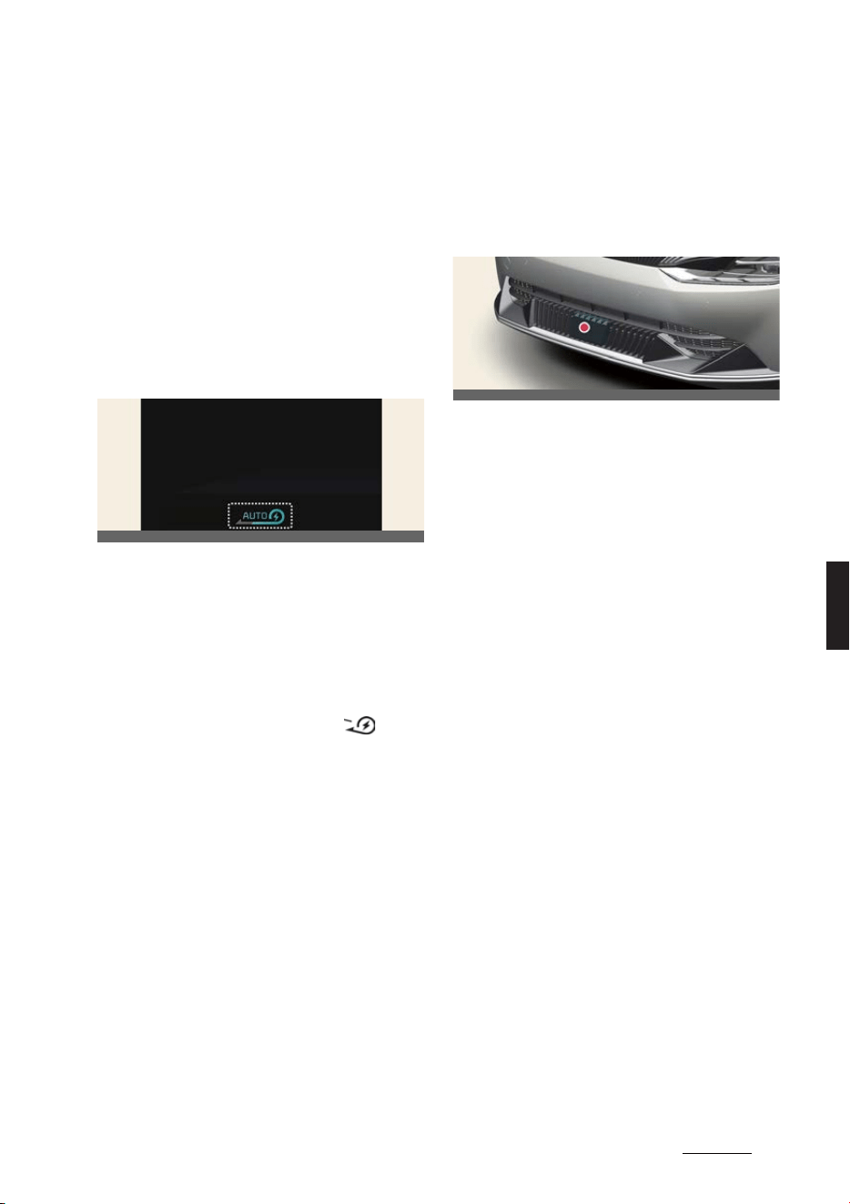
17
6
6
Driving your vehicle Smart regeneration system
Smart regeneration system
The Smart Regeneration System con
-
trols the regenerative braking automati
-
cally according to the road gradient and
driving condition of the vehicle in front.
The system minimizes the unnecessary
operation of the brake and acceleration
pedal, improving the electric efficiency
and assisting the driver.
Operating smart regeneration
system
Operation
1. Select
Settings
→
ECO Vehicle
→
Smart Recuperation
→
Faster decel
-
eration
/
Normal deceleration
/
Slow
deceleration
on the infotainment sys
-
tem.
2. Pull and hold the right side ( ) of
the paddle shifter for more than
approximately 1 second.
僅
AUTO
symbol will be displayed on
the cluster.
僅 The regenerative braking level can
be adjusted based on the driver's
deceleration style.
Operating condition(s)
僅 When the vehicle speed is above
approximately 10 km/h (6 mph)
僅 The road gradient changes
僅 Distance from the vehicle ahead
reduces or increases
僅 Speed of the vehicle ahead reduces or
increases
Detecting sensor
Front radar
Always make sure the radar sensor
cover is clean and free of dirt, snow, and
debris.
Dirt, snow, or foreign substances on the
lens may adversely affect the sensing
performance of the sensor. In this case,
the system operation may stop tempo
-
rarily and not operate normally.
Temporarily canceling smart
regeneration system
Operating condition(s)
僅 The vehicle is shifted to N (Neutral), R
(Reverse) or P (Park).
僅 Cruise Control or Smart Cruise Con
-
trol is operating.
僅 ESC (Electronic Stability Control) or
ABS is operating.
Setting default smart regenera
-
tion system level
Operation
僅 Pull the paddle shifter when the smart
regeneration system is ON. The level
adjustment by smart regeneration
system will operate above set level.
OCV041134L
OCV051005L
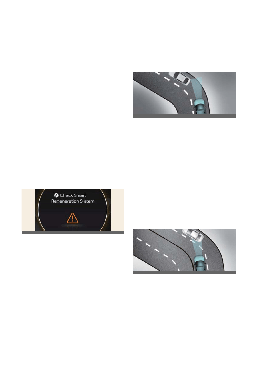
Driving your vehicle
186
Smart regeneration system
Resuming smart regeneration
system
Operation
僅 Pull and hold the right side of the pad
-
dle shifter for more than approxi
-
mately 1 second again.
Turning smart regeneration sys
-
tem off
Operation
僅 Pull and hold the right side of the pad
-
dle shifter for more than approxi
-
mately 1 second.
Smart regeneration system mal
-
function and limitations
Smart regeneration system mal
-
function
A:
Check Smart Regeneration System
The message will appear when the sys
-
tem is not functioning normally. The sys
-
tem will be canceled and the word
AUTO
on the cluster will disappear and
instead display regenerative braking
level. Check for foreign substances on
the front radar. Remove any dirt, snow,
or foreign material that could interfere
with the radar sensors. If the system still
does not operate normally, have the
vehicle inspected by a professional
workshop. Kia recommends visiting an
authorized Kia dealer/service partner.
Limitations of smart regeneration
system
Driving on a curved road
When driving on the curve, the system
may not detect the vehicle in your lane
and the regenerative braking level will
reduce automatically, making you feel
that the vehicle is accelerating.
Also, if the system suddenly recognizes
the vehicle in front, the regenerative
braking level will increase automatically,
making you feel that the vehicle is decel
-
erating.
The driver must maintain a safe braking
distance, and if necessary, depress the
brake pedal to reduce your driving
speed in order to maintain a safe dis
-
tance.
The smart regeneration system may rec
-
ognize a vehicle in an adjacent lane
when driving on a curved road. In this
case, the system increase the braking
level and slow the vehicle.
Always pay attention to road and driving
conditions while driving. If necessary,
depress the brake pedal to reduce your
driving speed in order to maintain a safe
distance. Also, when necessary, you may
OCV051114L
OCV051006L
OCV051007L
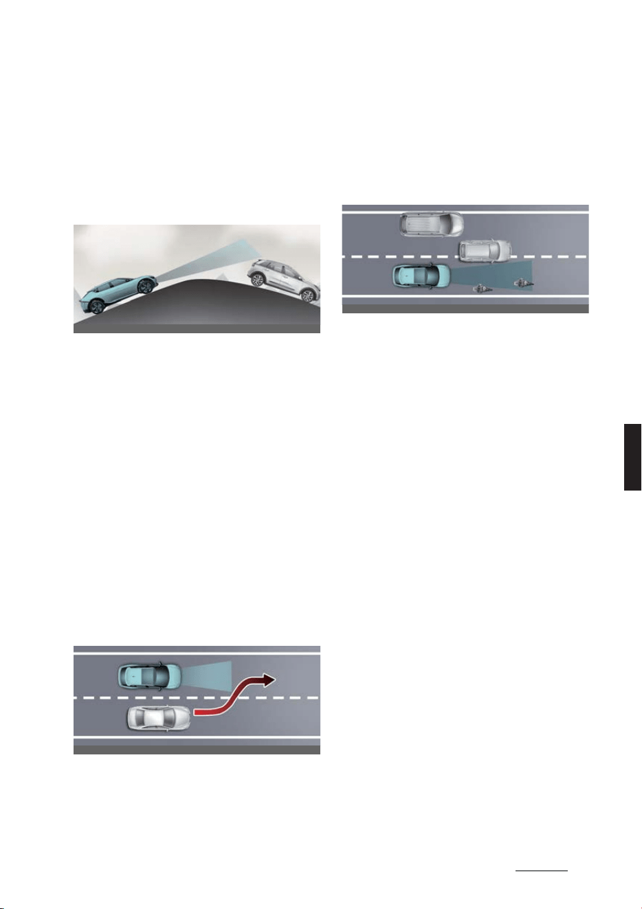
19
6
6
Driving your vehicle Smart regeneration system
depress the accelerator pedal to prevent
the system from unnecessarily deceler
-
ating your vehicle.
Always check the traffic conditions
around the vehicle.
Driving on a sloped road
When driving on an uphill or downhill,
the system may not detect the vehicle in
your lane and the regenerative braking
level will reduce automatically, making
you feel that the vehicle is accelerating.
Also, if the system suddenly recognizes
the vehicle in front, the regenerative
braking level will increase automatically,
making you feel that the vehicle is decel
-
erating.
The driver must maintain a safe braking
distance, and if necessary, depress the
brake pedal to reduce your driving
speed in order to maintain a safe dis
-
tance.
Changing lanes
When a vehicle changes lanes in front of
you, the smart regeneration system may
not immediately detect the vehicle,
especially if the vehicle changes lanes
abruptly. In this case, you must maintain
a safe braking distance, and if neces
-
sary, depress the brake pedal to reduce
your driving speed in order to maintain a
safe distance.
Recognizing the vehicle
Some vehicles in your lane cannot be
recognized by the sensor:
僅 Narrow vehicles such as motorcycles
or bicycles
僅 Vehicles offset to one side
僅 Slow-moving vehicles or sudden-
decelerating vehicles
僅 Stopped vehicles (When the vehicle
ahead drives away, the system may
not detect a stopped vehicle.)
僅 Vehicles with small rear profile such
as trailers with no loads
A vehicle ahead cannot be recognized
correctly by the sensor if any of follow
-
ing occurs:
僅 When the vehicle is pointing upwards
due to overloading in the luggage
compartment
僅 While the steering wheel is operating
僅 When driving to one side of the lane
僅 When driving on narrow lanes or on
curves
Apply the brake or accelerator pedal if
necessary.
OCV051008L
OCV051009L
OCV051010L

Driving your vehicle
206
Smart regeneration system
WARNING
僅 When vehicle speed is under 10 km/h
(6 mph), the Smart Regeneration Sys
-
tem is canceled. The driver must
adjust the vehicle speed by depress
-
ing the accelerator or brake pedal
according to the road condition ahead
and driving condition.
僅 Smart Regeneration System relies on
front view camera in the vehicle. For
-
eign substances on the front view
camera may cause the malfunction of
Smart Recuperation System. Be sure
to maintain clear view for the front
view camera.
僅 The Smart Regeneration System will
not operate when the Forward Colli
-
sion- Avoidance Assist (FCA) warning
light on the cluster is illuminated. The
driver must adjust the vehicle speed
by depressing the accelerator or
brake pedal according to the road
condition ahead and driving condi
-
tion.
僅 The Smart Regeneration System
which automatically controls the
regenerative braking level when
coasting is only a supplemental sys
-
tem for the driver's convenience. Do
not solely rely on this system to stop
the vehicle. The system cannot com
-
pletely stop the vehicle in all situations
nor avoid all collisions. The brake con
-
trol may be insufficient depending on
the speed of the vehicle in front and
when the vehicle in front suddenly
stops, a vehicle cuts in suddenly and
there is a steep slope. Always look
ahead cautiously to prevent unex
-
pected and sudden situations from
occurring.
僅 When the Smart Regeneration System
is canceled automatically, adjust the
vehicle speed directly by depressing
the accelerator or brake pedal accord
-
ing to the road and driving conditions
ahead.
僅 When using the Smart Regeneration
System take the following precau
-
tions:
- If an emergency stop is necessary,
you must apply the brakes.
- Keep a safe distance according to
road conditions and vehicle speed.
If the vehicle to vehicle distance is
too close during a high-speed driv
-
ing, a serious collision may result.
- Always maintain sufficient braking
distance and decelerate your vehi
-
cle by applying the brakes if neces
-
sary.
- The Smart Regeneration System is
designed to detect and monitor the
vehicle ahead in the roadway
through radar signals. It is not
designed to detect oncoming vehi
-
cles, pedestrians, bicycles, motor
-
cycles, or smaller wheeled objects
such as luggage bags, shopping
carts, or strollers.
- Vehicles moving in front of you with
a frequent lane change may cause
a delay in the system's reaction or
may cause the system to react to a
vehicle actually in an adjacent lane.
Always drive cautiously to prevent
unexpected and sudden situations
from occurring.
- The Smart Regeneration System
may not recognize complex driving
situations so always pay attention
to driving conditions and control
your vehicle speed.

21
6
6
Driving your vehicle Smart regeneration system
CAUTION
僅 Do not apply license plate frame or
foreign objects such as a bumper
sticker or a bumper guard near the
radar sensor. Doing so may adversely
affect the sensing performance of the
radar.
僅 Always keep the radar sensor and
lens cover clean and free of dirt and
debris.
僅 Use only a soft cloth to wash the vehi
-
cle. Do not spray pressurized water
directly on the sensor or sensor cover.
僅 Be careful not to apply unnecessary
force on the radar sensor or sensor
cover. If the sensor is forcibly moved
out of proper alignment, the Smart
Regeneration System may not oper
-
ate correctly. In this case, a warning
message may not be displayed. Have
the vehicle inspected by a profes
-
sional workshop. Kia recommends vis
-
iting an authorized Kia dealer/service
partner.
僅If the front bumper becomes dam
-
aged in the area around the radar
sensor, the Smart Regeneration Sys
-
tem may not operate properly. Have
the vehicle inspected by a profes
-
sional workshop. Kia recommends vis
-
iting an authorized Kia dealer/service
partner.
僅 Use only Kia Genuine Parts or those
of an equivalent standard to repair or
replace a damaged sensor or sensor
cover. Do not apply paint to the sen
-
sor cover
NOTICE
The Smart Regeneration System may
not operate temporarily due to:
僅 Electrical interference
僅 Modifying the suspension
僅 Differences of tire abrasion or tire
pressure
僅 Installing different type of tires

Driving your vehicle
226
Brake system
Brake system
In the event of brake failure
Operation
僅 Make an emergency stop with the
parking brake.
Operating condition(s)
僅 The brake has failed
Power-assisted brakes
Operation
僅 Apply greater force to the brake
pedal.
Operating condition(s)
僅 The vehicle is stalled
Brake over accelerator
Operation
1. Apply the brakes steady and firmly.
2. Stop the vehicle safely.
3. Shift to P. Turn off the vehicle and
apply the parking brake.
4. Inspect the accelerator pedal for any
interference.
Operating condition(s)
僅 The accelerator pedal is stuck
High Performance Brake
As this vehicle is equipped with the High
Performance Brake (largediameter
brakes for enhanced braking perfor
-
mance), noise such as a squeal, squeak
or groan is generated while braking. This
is normal and the friction may create cir
-
cle patterns on the disc surface. This is
also a normal situation which does not
affect braking performance.
NOTICE
僅 Occasional brake noise is normal. If a
continuous grinding or continuous
squeal sound is present, the brake lin
-
ing may be worn-out. Kia recom
-
mends to contact an authorized Kia
dealer/service partner.
僅 If the vehicle has continuous vibration
or shudder in the steering wheel while
braking, Kia recommends to contact
an authorized Kia dealer/service part
-
ner.
WARNING
Frequent speeding and braking may
deform components and wear the disc
brake causing vibration when braking.
Prevent brake damage by avoiding
excessive braking.
Brake wear, noise, vibration from exces
-
sive braking or deformation of the
brakes caused by repeatedly braking in
high speed, racing on tracks, etc. can be
excluded from warranty coverage.
Disc brakes wear indicator
The front or rear brakes will squeal when
the brake pads are worn. Always replace
the front or rear brake pads as pairs.
Brake disc cleaning
If there is a surface rust on the brake
disc or squeal can be heard, select level
0 of the regenerative brake system.
The regenerative brake system will be
temporarily deactivated to clean the
brake disc.
Depressing a brake while driving
approximately 10 times, the regenera
-
tive brake system will not be operated

23
6
6
Driving your vehicle Brake system
during Brake Disc Cleaning mode is acti
-
vated (Regenerative brake system level
0). The energy consumption may
increases.
After Brake Disc Cleaning mode oper
-
ates, the regenerative brake system will
activate again.
WARNING
僅 Avoid applying the parking brake to
stop the vehicle while it is moving
except in an emergency situation.
Applying the parking brake while the
vehicle is moving at normal speeds
can cause a sudden loss of control of
the vehicle. If you must use the park
-
ing brake to stop the vehicle, use
great caution in applying the brake.
僅 Avoid continuous application of the
brakes when descending a long or
steep hill. Continuous brake applica
-
tion will cause the brakes to overheat
and could result in a temporary loss of
braking performance.
僅 Do not ignore high pitched wear
sounds from your brakes. If you
ignore this audible warning, you will
eventually lose braking performance,
which could lead to a serious accident.
CAUTION
僅 Do not drive with your foot resting on
the brake pedal. This will create
abnormally high brake temperatures
which can cause excessive brake lin
-
ing and pad wear.
僅 Do not continue to drive with worn
brake pads. Continuing to drive with
worn brake pads can damage the
braking system and result in costly
brake repairs.
NOTICE
僅 Do not continue depressing the brake
pedal if the
READY
indicator is OFF.
The battery may be discharged.
僅 Noise and vibration generated during
braking is normal.
僅 Under normal operation, electric
brake pump noise and motor vibra
-
tion may occur temporarily in below
cases.
- When the pedal is depressed sud
-
denly.
- When the pedal is repeatedly
depressed in short intervals.
- When the ABS function is activated
while braking.
僅 If none are found and the condition
persists, have your vehicle towed to a
professional workshop and inspected.
Kia recommends visiting an autho
-
rized Kia dealer/service partner.
僅 Brake dust may accumulate on the
wheels, even under normal driving
conditions. Some dust is inevitable as
the brakes wear and contribute to
brake noise.
僅 The driving efficiency could decrease
due to regenerative system deacti
-
vated.
僅 When stepping on the brake pedal
under a certain driving or weather
condition. you may witness your car
make a sound of squealing or some
other noises. This is not a brake mal
-
function but a normal phenomenon.
僅 When driving on the road to which
deicing chemicals are applied, the
vehicle may witness noises from the
brake or abnormal abrasion of tires
because of such deicing chemicals.
You should operate brake additionally
so that you would be able to remove
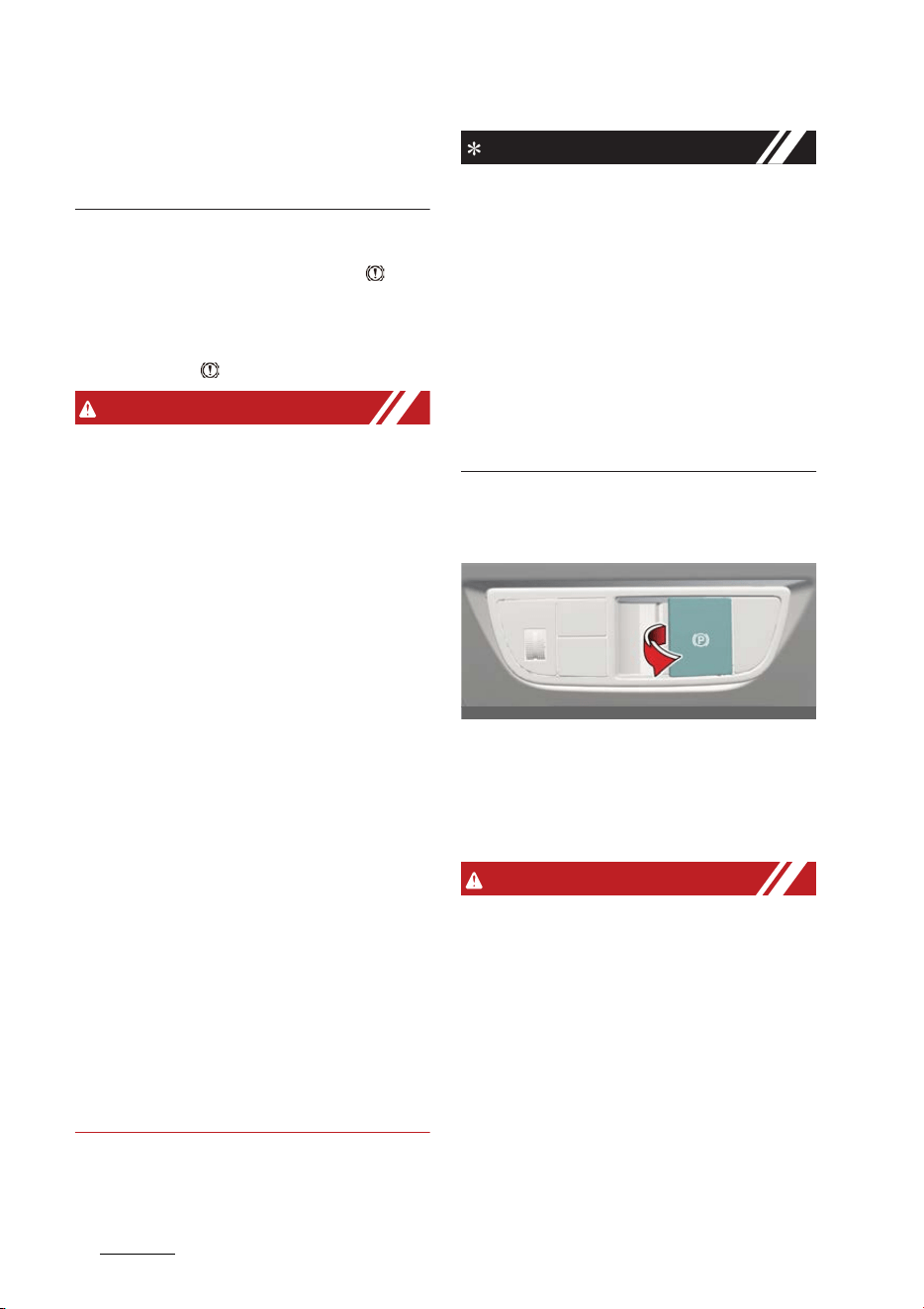
Driving your vehicle
246
Brake system
the deicing chemicals on the brake
disk and pad under a safe traffic con
-
dition.
Parking brake
Check if the brake warning light ( ) illu
-
minates when the vehicle is in the
START or ON position. Be sure the park
-
ing brake is fully released and the brake
warning light ( ) is off before driving.
WARNING
僅 To reduce the risk of SERIOUS
INJURY or DEATH, do not operate the
parking brake while the vehicle is
moving except in an emergency situa
-
tion. It could damage the brake sys
-
tem and lead to an accident.
僅 Whenever leaving the vehicle or park
-
ing, always come to a complete stop
and continue to depress the brake
pedal. Make sure the gear is shifted to
P (Park) position, then apply the park
-
ing brake, and set the EV button to
OFF position. Vehicles with the park
-
ing brake not fully engaged are at risk
for moving inadvertently and causing
injury to yourself or others.
僅 NEVER allow anyone who is unfamil
-
iar with the vehicle to touch the park
-
ing brake. If the parking brake is
released unintentionally, serious
injury may occur.
僅 Only release the parking brake when
you are seated inside the vehicle with
your foot firmly on the brake pedal.
僅 Never allow a passenger to touch the
parking brake. If the parking brake is
released unintentionally, serious
injury may occur.
NOTICE
僅 Do not apply the accelerator pedal
while the parking brake is engaged. If
you depress the accelerator pedal
with the parking brake engaged,
warning will sound. Damage to the
parking brake may occur.
僅 Driving with the parking brake on can
overheat the braking system and
cause premature wear or damage to
brake parts. Make sure the parking
brake is released and the brake warn
-
ing light is off before driving.
Electronic Parking Brake EPB
Applying the EPB manually
Operation
僅 Depress the brake pedal and pull the
EPB switch up to apply the parking
brake.
WARNING
僅 Risk of accident and injury due to chil
-
dren left unattended in the vehicle. If
you leave children unaccompanied in
the vehicle, they may be able to set
the vehicle in motion, for example by:
- Releasing the parking brake.
- Shifting the gear out of P (Park)
position.
- Starting the vehicle. In addition,
they may operate vehicle equip
-
ment.
OCV051011L

25
6
6
Driving your vehicle Brake system
僅 Never leave children and animals
unattended in the vehicle.
僅 When leaving the vehicle, always take
the smart key with you and lock the
vehicle.
NOTICE
僅 On a steep incline or when pulling a
trailer, if the vehicle does not remain
at a standstill, do as follows:
- Apply the EPB.
- Pull up the EPB switch for more
than 3 seconds.
僅 A click or electric brake motor whine
sound may be heard while operating
or releasing the EPB. These conditions
are normal and indicate that the EPB
is functioning properly.
Applying the EPB automatically
Operating condition(s)
僅Shifting to P (Park).
僅 Vehicle in OFF position with AUTO
HOLD enabled
僅 When the vehicle moves a bit in P
僅 At the request of other systems.
僅 The conditions below apply when
Auto Hold is enabled:
- The driver's door is opened.
- The hood is opened.
- The tailgate is opened.
- The vehicle stops for more than
approximately 10 minutes on a
steep slope
- At the request of other systems.
僅 If equipped with Electronic Parking
Brake, parking brake is applied auto
-
matically when the gear is shifted to P
(Park).
CAUTION
僅 If you notice a continuous noise or
burning smell when the EPB is used
for emergency braking, have your
vehicle checked by a professional
workshop. Kia recommends to visit an
authorized Kia dealer/service partner.
僅 If the gear is shifted to N (Neutral)
while Electronic Parking Brake is
applied, it is not released automati
-
cally. If you don't release Electronic
Parking Brake manually before using
an automatic car wash tunnel
machine or etc., this may result in
damage to the vehicle or the auto
-
matic car wash tunnel machine.
NOTICE
For Electronic Parking Brake
EPB
equipped vehicles with AUTO HOLD
function used while driving, if the EV
button is in OFF position, the EPB will be
engaged automatically. Therefore,
AUTO HOLD function should be turned
off before the EV button is in OFF posi
-
tion.
Releasing EPB manually
Operation
僅 Depress the brake pedal. Make sure
the gear is in P and push the EPB
switch down to release the parking
brake.
Releasing EPB automatically
Operation
1. Start the vehicle.
2. Fasten the driver's seat belt.

Driving your vehicle
266
Brake system
3. Close the driver's door, hood and tail
-
gate.
4. When the vehicle is ON, depress the
brake pedal and shift to R or D.
5. Depress the accelerator pedal while
the gear is in R, D or manual mode.
WARNING
僅 Never allow a passenger, children, or
animal to touch the Electronic Parking
Brake.
僅 Do not input any other objects around
the Electronic Parking Brake. It may
be operated unintentionally.
CAUTION
僅 Do not drive your vehicle with the EPB
applied. It may cause excessive brake
pad and brake rotor wear.
僅 Whenever leaving the vehicle or park
-
ing, make sure the gear is shifted to P
(Park) position, then apply the parking
brake. Block the tires if necessary.
僅 Electronic Parking Brake may not be
released because it can freeze in win
-
ter. Do not use Electronic Parking
Brake and shift the gear to P (Park),
block the tires, and park the vehicle
on the flat and safe road. If the Elec
-
tronic Parking Brake is applied when
you shift the gear to P (Park), release
the Auto Hold and Electronic Parking
Brake, and park the vehicle with the
tires blocked.
僅 When driving with the Electronic Park
-
ing Brake applied, brake system may
be overheated, brake lines may be
worn, and the Electronic Parking
Brake may be damaged.
僅 A click or electric brake motor whine
sound may be heard while operating
or releasing the Electronic Parking
Brake.
僅If you hand over the vehicle to other
people, make sure they understand
how to use the Electronic Parking
Brake for safety.
僅When the battery charge is not suffi
-
cient, Electronic Parking Brake may
not be applied or released. In this
case, connect to the auxiliary battery.
NOTICE
僅 For the Middle East, EPB is released
regardless of seat belt fastening.
僅 Do not follow these procedures when
driving on a flat level ground. The
vehicle may suddenly move forward:
- For your safety, depress the brake
pedal and release the parking
brake manually with the EPB switch
when you drive downhill or when
Reversing the vehicle.
- For your safety, you can engage
the EPB even though the vehicle is
in the OFF position, but you cannot
release it.
僅 If the parking brake warning light is
still on even though the EPB has been
released, have the system checked by
a professional workshop. Kia recom
-
mends visiting an authorized Kia
dealer/service partner.
EPB warning message
Operating condition(s)
僅 Attempting to drive off using the
accelerator pedal with the EPB
applied
僅 Driver's seat belt is not fastened and
the vehicle hood, driver's door or the
tailgate is opened.
僅 There is a problem with the vehicle

27
6
6
Driving your vehicle Brake system
僅 Conversion from AUTO HOLD to EPB
is not working properly
僅 EPB is applied while AUTO HOLD is
activated due to Electronic Stability
Control (ESC) signal
EPB malfunction indicator
If the EPB malfunction indicator remains
on, turns on while driving, or does not
turn on when the vehicle is in the ON
position, this indicates that the EPB may
be malfunctioning.
Have your vehicle checked by a profes
-
sional workshop as soon as possible. Kia
recommends to visit an authorized Kia
dealer/service partner.
NOTICE
僅 The EPB warning light may illuminate
if the EPB switch operates abnormally.
Shut the vehicle off and turn it on
again after a few minutes. The warn
-
ing light will go off and the EPB switch
will operate normally. However, if the
EPB warning light is still on, have the
system checked by a professional
workshop. Kia recommends to visit an
authorized Kia dealer/service partner.
僅 If the parking brake warning light
does not illuminate or blinks even
though the EPB switch was pulled up,
the EPB is not applied.
僅 If the parking brake warning light
blinks when the EPB warning light is
on, press the EPB switch, then pull it
up. Once more press it back to its
original position and pull it back up. If
the EPB warning does not go off, have
the system checked by a professional
workshop. Kia recommends to visit an
authorized Kia dealer/service partner.
Emergency braking with the EPB
switch
Operation
僅 Pull and hold the EPB switch up to
engage the emergency brake.
WARNING
Do not operate the Electronic Parking
Brake
EPB
while the vehicle is moving
except in an emergency situation. Apply
-
ing the EPB while the vehicle is moving
at normal speeds can cause a sudden
loss of control of the vehicle. If you must
use the EPB to stop the vehicle, use
great caution in applying the brake.
NOTICE
During emergency braking by the EPB,
the parking brake warning light will illu
-
minate to indicate that the system is
operating.
When the EPB does not release
properly
Operation
1. Load the vehicle on a flatbed tow
truck.
2. Take your vehicle to a professional
workshop to check the system. Kia
recommends visiting an authorized
Kia dealer/service partner.
OCV041136L
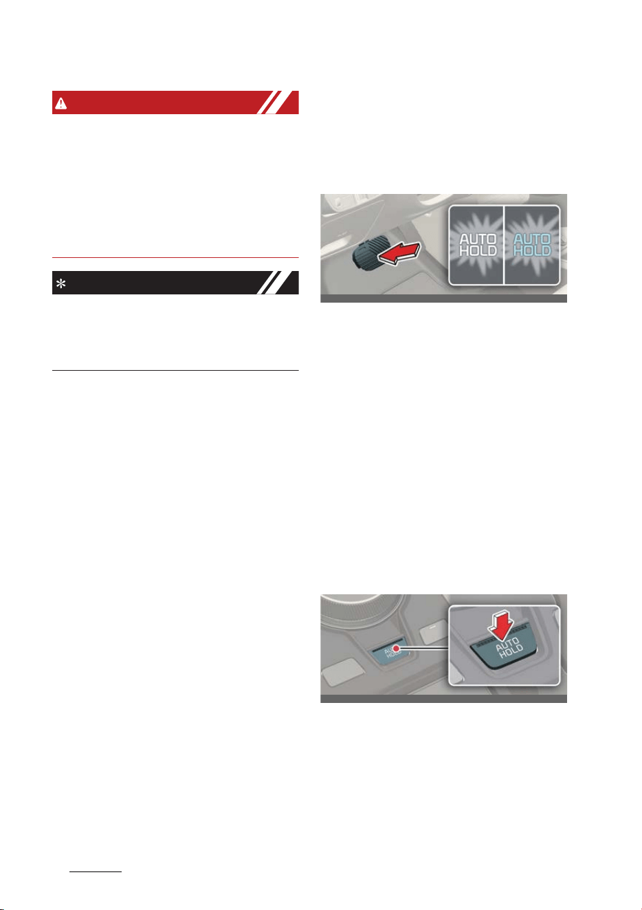
Driving your vehicle
286
Brake system
WARNING
Do not operate the Electronic Parking
Brake
EPB
while the vehicle is moving
except in an emergency situation. Apply
-
ing the EPB while the vehicle is moving
at normal speeds can cause a sudden
loss of control of the vehicle. If you must
use the EPB to stop the vehicle, use
great caution in applying the brake.
NOTICE
During emergency braking by the EPB,
the parking brake warning light will illu
-
minate to indicate that the system is
operating.
AUTO HOLD
The AUTO HOLD maintains the vehicle
in a stopped position without depressing
the brake pedal.
Applying AUTO HOLD
Operation
1. Press the AUTO HOLD button. The
AUTO HOLD indicator will light up in
white.
2. The AUTO HOLD indicator changes
from white to green when the vehicle
is stopped.
3. AUTO HOLD will be released auto
-
matically when the accelerator pedal
is pressed in D, R, or manual mode.
The AUTO HOLD indicator will change
from green to white.
4. Press the AUTO HOLD button again
while pressing the brake pedal to can
-
cel the AUTO HOLD operation.
Operating condition(s)
僅 Brake pedal is depressed after the
vehicle has started.
OCV051012L_2
OCV051013L

29
6
6
Driving your vehicle Vehicle safety system
Non-operating condition(s)
僅 P (Park) gear position is selected.
僅 The EPB is applied.
AUTO HOLD warning messages
Operating condition(s)
僅 When the EPB is automatically applied
from AUTO HOLD
僅 AUTO HOLD to EPB conversion is not
working properly
僅 Brake pedal is not applied when the
AUTO HOLD button is pressed
WARNING
To reduce the risk of an accident, do not
activate AUTO HOLD while driving
downhill, Reversing or parking your
vehicle.
NOTICE
僅 If the AUTO HOLD indicator lights up
yellow, the AUTO HOLD is not work
-
ing properly. Take your vehicle to a
professional workshop and have the
system checked. Kia recommends vis
-
iting an authorized Kia dealer/service
partner.
僅 A click or electric brake motor whine
sound may be heard while operating
or releasing the EPB, but these condi
-
tions are normal and indicate that the
EPB is functioning properly.
僅 If the vehicle is restarted with the Auto
Hold system is in the standby position
or operating, the Auto hold system will
continue to operate in the standby
position.
Vehicle safety system
Anti-lock Brake System (ABS)
The Anti-lock Brake System (ABS) pre
-
vents the wheels from locking up in
order to steer and stabilize the vehicle.
If the ABS warning light ( ) stays on,
contact a professional workshop as soon
as possible. Kia recommends visiting an
authorized Kia dealer/service partner.
NOTICE
僅 A click sound may be heard in the
vehicle compartment when the vehi
-
cle begins to move after the vehicle is
started. These conditions are normal
and indicate that the Anti-lock Brake
System is functioning properly.
僅 When you jump start your vehicle
because of a drained battery, the
vehicle may not run as smoothly and
the ABS warning light may turn on at
the same time. This happens because
of low battery voltage. It does not
mean your ABS has malfunctioned.
- Do not pump your brakes!
- Have the battery recharged before
driving the vehicle.
Electronic Stability Control (ESC)
Electronic Stability Control (ESC) is
designed to stabilize the vehicle during
cornering maneuvers.
ESC is not a substitute for safe driving
practices. Factors such as speed, road
conditions, and driver steering input can
all affect whether ESC will be effective in
preventing loss of control.
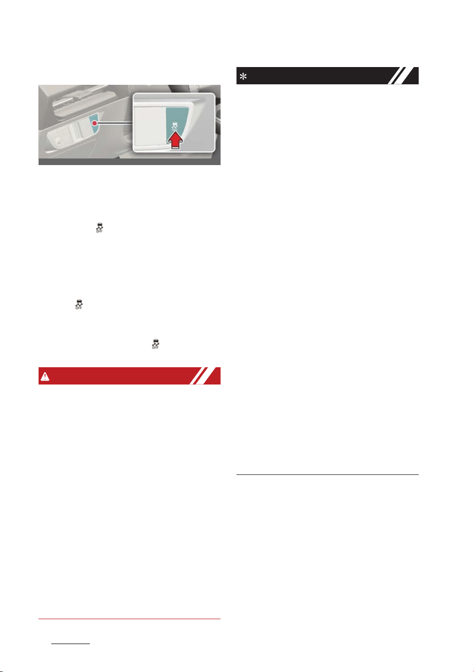
Driving your vehicle
306
Vehicle safety system
Operating ESC
Operation
僅 Press the ESC OFF button for approxi
-
mately half a second to turn ESC off.
ESC OFF ( ) indicator light will illumi
-
nate and the warning chime will
sound.
僅 Press and hold the ESC OFF button
again for approximately 3 seconds to
turn ESC and traction control off. ESC
OFF ( ) indicator light will illuminate
and the warning chime will sound.
僅 To turn ESC on again, press the ESC
OFF button. ESC OFF ( ) indicator
light will go off.
WARNING
僅 For maximum protection, always wear
your seat belt. No system, no matter
how advanced, can compensate for
all driver error and/or driving condi
-
tions. Always drive responsibly.
僅 Drive carefully even though your vehi
-
cle has Electronic Stability Control. It
can only assist you in maintaining
control under certain circumstances.
僅 When ESC (electric vehicle control) is
deactivated, the vehicle will loose the
traction and stability if the vehicle is
driven by abrupt steering wheel con
-
trol. It is possible that the tire may
make a collision with the connected
parts of the tire. We recommend to do
not turn off ESC while driving the
vehicle for your safety.
NOTICE
僅 A click sound may be heard in the
vehicle compartment when the vehi
-
cle begins to move after the vehicle is
started. These conditions are normal
and indicate that the Electronic Stabil
-
ity Control system is functioning prop
-
erly.
僅When operating the vehicle on a
dynamometer, ensure that the ESC is
turned off (ESC OFF light illuminated).
If the ESC is left on, it may prevent the
vehicle speed from increasing, and
result in false diagnosis.
僅 Turning the ESC off does not affect
ABS or brake system operation.
僅 Select level 0 of the regenerative
braking system and depress the
brake pedal around 10 times to effi
-
ciently apply brake disc cleaning.
僅 Brake disc cleaning may decrease the
driving distance by restraining the
regenerative braking system. After
brake disc cleaning, the regenerative
braking system may be restored by
selecting any other recuperation level
other than 0.
僅 If the regenerative braking system is
not restored after the brake disc
cleaning, Kia recommends visiting an
authorized Kia dealer/service partner.
Hill-start Assist Control (HAC)
Hill-start Assist Control (HAC) prevents
the vehicle from rolling back by applying
the brakes automatically for approxi
-
mately 2 seconds (maximum of 5 sec
-
onds when the accelerator pedal is
slightly depressed during HAC opera
-
tion).
OCV051014L

31
6
6
Driving your vehicle Vehicle safety system
The brakes are released when the accel
-
erator pedal is engaged or after approxi
-
mately 2 seconds.
WARNING
HAC does not replace the need to apply
brakes while stopped on an incline.
While stopped, make sure you maintain
brake pressure sufficient to prevent your
vehicle from rolling backward and caus
-
ing an accident. Don't release the brake
pedal until you are ready to accelerate
forward.
Multi-Collision Brake (MCB)
Multi-Collision Brake controls the brake
automatically in the event of an accident
where the air bag deploys to reduce the
risk of additional accidents that may
occur.
System operation
僅 From the time the air bag deploys,
Multi-Collision Brake monitors the
depression intensity of the brake
pedal and accelerator pedal for a
short period. The system operates
when the following conditions are
met:
- Vehicle speed is under 180 km/h
(112 mph) at the time of collision.
- The brake pedal and accelerator
pedal are hardly depressed.
僅 When the driver steps on the brake
pedal over a certain level while Multi-
Collision Brake is active, the braking
power takes priority over automatic
braking by Multi-Collision Brake sys
-
tem. However, if the driver takes his/
her foot off the brake pedal, Multi-
Collision Brake system will maintain
automatic braking.
System off
僅 Multi-Collision Brake is canceled in
the following situations:
- The accelerator pedal is depressed
over a certain level.
- The vehicle stops.
- ESC (Electronic Stability Control) or
electronic devices has malfunc
-
tioned.
- In a situation system cannot oper
-
ate normally.
- Ten seconds have passed since the
brake has been controlled auto
-
matically by Multi-Collision Brake
system.
WARNING
僅 Multi-Collision Brake decreases vehi
-
cle speed after a collision and reduces
the risk of a second collision, but it
does not prevent a second collision.
You may drive away from the collision
spot to avoid other dangerous situa
-
tions by depressing the accelerator
pedal.
僅 After the vehicle is stopped by Multi
Collision Brake, the system stops con
-
trolling the brakes.
Depending on the situation, the driver
should depress the brake or the accel
-
erator pedal to prevent further acci
-
dents.
Vehicle Stability Management
(VSM)
Vehicle Stability Management (VSM)
provides further enhancements to vehi
-
cle stability and steering response.
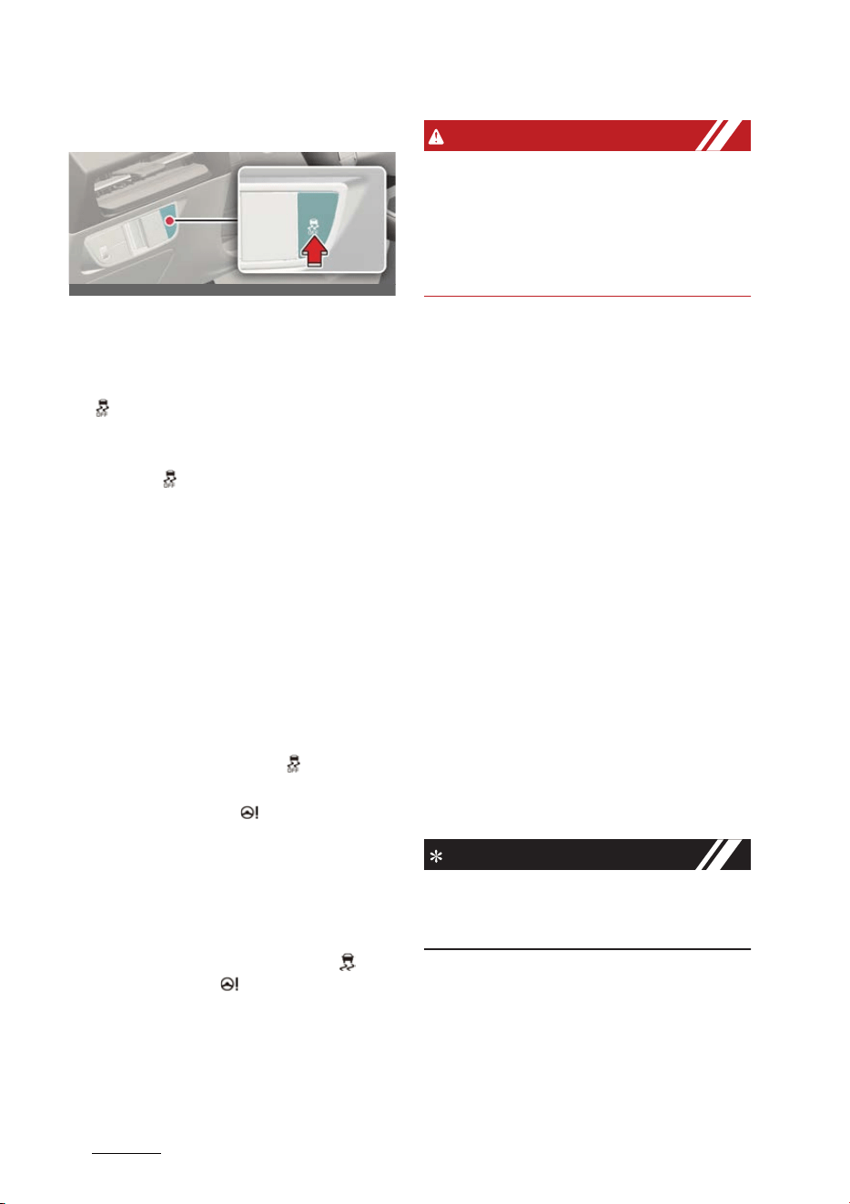
Driving your vehicle
326
Vehicle safety system
Operating VSM
Operation
僅 Press the ESC OFF button to turn VSM
off and the ESC OFF indicator light
( ) is illuminated.
僅 Press the ESC OFF button again to
turn VSM on and the ESC OFF indica
-
tor light ( ) will go off.
Operating condition(s)
僅 Driving on slippery roads
僅 Grip change of left and right wheels is
detected
Non-operating condition(s)
僅 Driving on a gradient or inclined sur
-
face
僅 Driving in reverse.
僅 ESC OFF indicator light ( ) remains
illuminated
僅 EPS warning light ( ) remains illumi
-
nated
VSM malfunction indicator
VSM can be deactivated when a mal
-
function has been detected in the Elec
-
tronic Power Steering system or VSM
system. If the ESC indicator light ( ) or
EPS warning light ( ) remains on, take
your vehicle to a professional workshop
and have the system checked. Kia rec
-
ommends visiting an authorized Kia
dealer/service partner.
WARNING
When replacing tires and wheels, make
sure they are the same size as the origi
-
nal tires and wheels installed. Driving
with varying tire or wheel sizes may
diminish any supplemental safety bene
-
fits of the VSM system.
Emergency Stop Signal (ESS)
The Emergency Stop Signal (ESS) alerts
the driver behind by flashing the brake
lights when braking sharply and
severely.
Operating condition(s)
僅 The vehicle suddenly stops.
僅 ABS is activated and the driving speed
is over 55 km/h (34 mph).
僅 The hazard warning flasher automati
-
cally turns ON after blinking the brake
lights when:
- The driving speed is under 40 km/h
(25 mph)
- The ABS is deactivated
- The sudden braking is over
僅 The hazard warning flasher turns OFF
when:
- The vehicle drives at a low speed
for a certain period of time.
NOTICE
The Emergency Stop Signal (ESS) sys
-
tem will not activate, when the hazard
warning flashers are already on.
Brake Assist System (BAS)
The Brake Assistant System provides
additional pressure when the brake
pedal is momentarily and strongly
depressed in a situation sudden braking
is required while driving.
OCV051014L
33
6
6
Driving your vehicle Electronic Limited Slip Differential (For GT)
The Brake Assistant System reduces the
time for ABS(Anti-Lock Brake System)
control to enter and consequently
reduces the braking distance, by provid
-
ing additional pressure up to the point of
ABS intervention.
BAS operation
僅 When the vehicle speed is more than
30 km/h (20 mph) and the ABS con
-
trol is not entered.
僅 When the brake pedal is depressed
strongly over a certain level.
僅 When the friction of the road surface
is above a certain level.
BAS operation off
僅 The vehicle speed is below 10 km/h (6
mph).
僅 The brake pedal is depressed over a
certain conditions.
僅 The friction of the road surface is
below a certain level.
WARNING
The system may not operate depending
on driver's driving habit, the degree to
which the brake pedal is depressed and
the road surface condition.
Electronic Limited Slip Differ
-
ential (For GT)
Electronic Limited Slip Differential con
-
trols the differential functions of the
wheels to help:
僅 Improve steering performance when
circling at high speed.
僅 Improve launching performance.
僅 Prevent slipping on rainy or snowy
roads due to dissimilar friction of the
left and right wheels.
WARNING
Never run the wheels with one of wheels
lifted on a jack. It is extremely dangerous
for a vehicle equipped with Electronic
Limited Slip Differential.
Drive Mode Selection
The characteristic of Electronic Limited
Slip Differential varies according to
which drive mode is selected by using
the DRIVE MODE switch.
For more details, refer to "Drive mode
integrated control system" on page 6-
35"
Selected mode Characteristic of e-LSD
ECO / NORMAL
NORMAL
SPORT
SPORT
GT
SPORT+
MY DRIVE
NORMAL/SPORT/SPORT+

Driving your vehicle
346
Electronic Control Suspension
Warning Messages
Electronic Limited Slip Differen
-
tial temporarily disabled due to
overheating
Overheating of related parts will tempo
-
rarily disable Electronic Limited Slip Dif
-
ferential. Wait until the vehicle cools
down.
Limited-slip differential disabled.
Tire diameter mismatch / Tire size
mismatch. Limited-slip differen
-
tial disabled. Check tire sizes
If your vehicle is equipped with different
tires (size, type, etc.), the message will
appear. To use Electronic Limited Slip
Differential, equip the vehicle with the
same tires.
Check Limited Slip Differential
When Electronic Limited Slip Differential
is not working properly, this warning
message will appear on the cluster LCD
display. If this occurs, Kia recommends
visiting an authorized Kia dealer/service
partner.
Electronic Control Suspension
(if equipped)
Electronic Control Suspension controls
the vehicle suspension automatically
using vehicle sensors to maximize driv
-
ing comfort by taking into account the
driving conditions such as speed, sur
-
face of the road, cornering, stopping
requirements and acceleration.
System Malfunction
A :
Check Electronic Suspension
When Electronic Control Suspension is
not working properly, this warning mes
-
sage will appear on the cluster LCD dis
-
play. If this occurs, Kia recommends the
system inspected by an authorized Kia
dealer/service partner.
OCVGT042191L
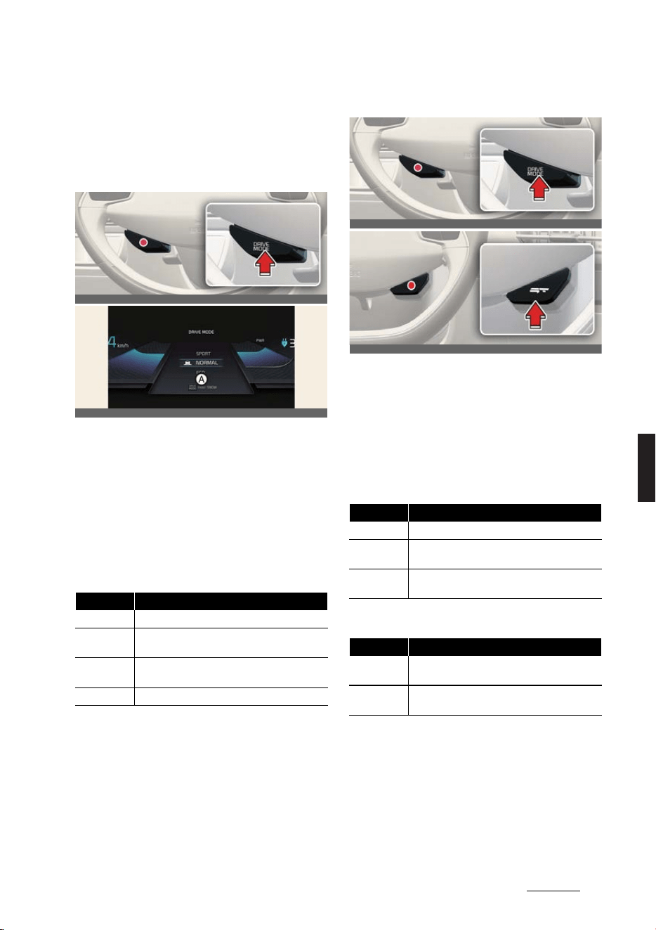
35
6
6
Driving your vehicle Drive mode integrated control system
Drive mode integrated control
system
DRIVE MODE
Selecting DRIVE MODE
A:
Hold
Operation
僅
DRIVE MODE
will change to
NOR
-
MAL
mode when the vehicle is
restarted.
ECO
mode will be main
-
tained when the vehicle is restarted.
僅 Press the
DRIVE MODE
button.
Selecting DRIVE MODE (For GT)
Operation
僅
DRIVE MODE
will change to
NOR
-
MAL
mode when the vehicle is
restarted.
ECO
mode will be main
-
tained when the vehicle is restarted.
僅 Press the
DRIVE MODE
button.
僅 Press the
GT
button.
Mode Characteristics
SPORT
Provides sporty but firm riding
NORMAL
Driving on general roads, city center and high
-
ways
ECO
Improves electric energy efficiency for eco-
friendly driving
SNOW
Provides safe driving on the snowy roads
OCV051015L
OCV051115L
Mode Characteristics
SPORT
Provides sporty but firm riding
NORMAL
Driving on general roads, city center and high
-
ways
ECO
Improves electric energy efficiency for eco-
friendly driving
Mode Characteristics
GT
Provides sportier and firm riding for maximum
performance
MY DRIVE
MODE
Adjustsmodes of each driving system.
OCV051015L
OCVGT052281L
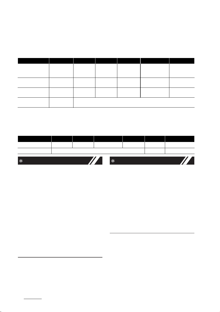
Driving your vehicle
366
Drive mode integrated control system
DRIVE MODE characteristics for 4WD (if equipped)
DRIVE MODE/GT button
* :Press the
GT
button.
Infotainment system
NOTICE
僅 If there is a problem with the instru
-
ment cluster, the drive mode will be in
NORMAL
mode and may not change
to
ECO
mode or
SPORT
mode.
僅 Efficiency depends on the driver's
driving habit and road condition.
僅In
SPORT
mode, the electric energy
efficiency may decrease.
僅 When you mildly drive the vehicle in
NORMAL
mode, the driving mode
changes to
ECO
mode to improve
electric energy efficiency. However,
the actual efficiency may differ in
accordance with your driving situa
-
tions.
INFORMATION
It is possible to set the climate system
control and brake mode separately.
Select
Settings
→
Vehicle
→
Drive
mode
→
Brake mode
or
ECO mode cli
-
mate control
from the infotainment sys
-
tem.
The infotainment system may change
after software updates. For more infor
-
mation, refer to the manual provided in
the infotainment system and the quick
reference guide.
DRIVE MODE SNOW NORMAL ECO SPORT GT
*
MY DRIVE
*
Characteristics Snow driving
Normal driv
-
ing mode
High electric
energy effi
-
ciency mode
Sporty driving
mode
More sportier and
firm riding mode
Adjusts modes of
each driving sys
-
tem
Button activation
Press more than
1 second
Press Press Press Press Press
Cluster indicator
SNOW
NORMAL
(Popup)
ECO SPORT GT MY
Regenerative braking
level
0~1 0~3
DRIVE MODE SNOW NORMAL ECO SPORT
GT
MY DRIVE
Climate system control
NORMAL NORMAL ECO
/
NORMAL
*
NORMAL NORMAL NORMAL
Brake mode
NORMAL
/
SPORT
* -
NORMAL
/
SPORT
*

37
6
6
Driving your vehicle Drift Mode (For GT)
Drift Mode (For GT)
Drift Mode is a driving mode that auto
-
matically activates rear wheels(2WD)
and brakes or Electronic Limited Slip Dif
-
ferential(e-LSD) to easily achieve drift
with a small steering wheel angle and
accelerator pedal
To Activate Drift Mode
Pull and hold the left and right paddle
shift levers for more than 3 seconds at
the same time to switch to drift mode.
When activated Drift Mode, the message
"Drift Mode activated" and the Drift indi
-
cator will illuminate on the instrument
panel.
To activate the Drift Mode, satisfy all of
the following conditions:
僅 Gear in P (Park)
僅 ESC off is in state 2 (completely push
the ESC OFF button for 3-5 second)
僅 The drive mode is SPORT or GT mode
僅 Depress the brake pedal to the bot
-
tom
Drift Mode Disabled
The DRIFT mode will be cancelled or lim
-
ited when:
僅 If the driving mode is changed to a
mode other than SPORT or GT mode
during DRIFT mode operation
僅 The ESC OFF stage 2 is released
僅 When pull and hold the left and right
paddle shift levers for more than 3
seconds at the same times during
DRIFT mode operation
僅 The power down indicator light ( )
or service warning( ) indicator is
illuminate
僅 The ESC or e-LSD indicator is illumi
-
nate
WARNING
僅 The driver should hold the responsi
-
bility to safely drive and control the
vehicle when using DRIFT mode.
僅 Use the drift mode in wide and flat
road surface without pedestrians,
vehicles or obstacles for the safety of
vehicles and pedestrians.
僅 Always look ahead cautiously to pre
-
vent unexpected and sudden situa
-
tions from occurring.
僅 If you drive in DRIFT mode continu
-
ously, it can cause premature wear or
damage to your drive shafts, brake
components and reduction gear.

Driving your vehicle
386
Maximum Power Output Mode (For GT)
Maximum Power Output Mode
(For GT)
Maximum Power Output Mode opti
-
mizes temperature of power electric sys
-
tems including high voltage battery to
provide high acceleration performance
of the GT. Available power output will be
displayed on the split screen when this
mode is activated.
To Activate Maximum Power
Output Mode
With the vehicle on, select Maximum
Power Output Mode in the split screen
from the infotainment system. Maximum
Power Output Mode can be turned on
and off with the activation button on the
screen. It will be automatically turned off
when EV ready is turned off.
Maximum Power Output Mode will not
be activated when one of the following
conditions are not satisfied. In this case,
Maximum Power Output Mode button
will be inactivated.
僅EV Ready
僅 70% or more of SOC
僅 Power electric system status is in nor
-
mal
Maximum Power Output Mode
deactivation
Maximum Power Output Mode can be
automatically turned off when one of the
following conditions are not met.
僅EV Ready
僅 70% or more of SOC
僅 Power electric system status is in nor
-
mal
WARNING
When Maximum Power Output Mode is
turned on, additional power could be
consumed by thermal optimization of
power electric system by which the driv
-
ing range of electric vehicle could be
reduced.

39
6
6
Driving your vehicle All wheel drive (4WD)
All wheel drive (4WD) (if
equipped)
When All Wheel Drive (4WD) is activated,
driving forces are distributed appropri
-
ately to front and rear wheels. It could
improve driving performance by maxi
-
mizing the driving force of vehicles on
severe road conditions such as steep
hills, unpaved, slippery, etc.
Advantage of electronic 4WD
僅 Improvement of straight stability
僅 Improvement of driving performance
on curve
僅 Secure stability on severe condition
such as wet and sandy roads.
僅 Improvement of energy efficiency
from driving mode automatic control.
For safe 4WD operation
Before driving
僅 Make sure all passengers are wearing
seat belts.
僅 Sit upright and closer to the steering
wheel than usual. Adjust the steering
wheel to a position comfortable for
you to drive.
Driving on snow-covered or icy
roads
僅 Start off slowly by applying the accel
-
erator pedal gently
僅 Use snow tires or tire chains.
僅 Keep sufficient distance between your
vehicle and the vehicle in front of you.
僅 Using the regenerative braking helps
the steering on the downhill. However
it is difficult to adjust the vehicle while
coasting, so avoid using the third level
of regenerative braking as much as
possible.
僅 Avoid speeding, rapid acceleration,
sudden brake applications, and sharp
turns to prevent skids.
僅 It is difficult to start again if the vehicle
stops on an uphill road. Keep your dis
-
tance from other vehicles and drive
slowly.
Driving in sand or mud
僅 Maintain a slow, constant speed.
僅 Use tire chains driving in mud if nec
-
essary.
僅 Keep sufficient distance between your
vehicle and the vehicle in front of you.
僅 Reduce vehicle speed and always
check the road condition.
僅 Avoid speeding, rapid acceleration,
sudden brake applications, and sharp
turns to prevent getting stuck.
Driving up or down hills
僅 Driving uphill
- Before starting off, check if it is
possible to drive uphill.
僅 Driving downhill
- Drive straight as possible.
Driving through water
僅 Try to avoid driving in deep standing
water.
僅 If you need to drive in water, stop
your vehicle, set the vehicle in Multi
Terrain mode and drive under 8 km/h
(5 mph).
僅 Do not change gear while driving in
water.

Driving your vehicle
406
All wheel drive (4WD)
Additional driving conditions
僅 Become familiar with the off-road
conditions before driving.
僅 Always pay attention when driving
off-road and avoid dangerous areas.
僅 Drive slowly when driving in heavy
wind.
僅 Reduce vehicle speed when corner
-
ing. The center of gravity of 4WD
vehicles is higher than conventional
2WD vehicles, making them more
likely to roll over when you rapidly
turn corners.
僅 Always hold the steering wheel firmly
when you are driving off-road.
WARNING
僅 If the 4WD warning light ( ) stays on
the instrument cluster, your vehicle
may have a malfunction with the 4WD
system. When the 4WD warning light
( ) illuminates, have your vehicle
checked by a professional workshop.
Kia recommends visiting an autho
-
rized Kia dealer/service partner.
僅 Do not drive in conditions that exceed
the vehicles intended design such as
challenging off-road conditions.
僅 Avoid high speeds when cornering or
turning.
僅 Do not make quick steering wheel
movements, such as sharp lane
changes or fast, sharp turns.
僅 The risk of a rollover is greatly
increased if you lose control of your
vehicle at highway speeds.
僅 Loss of control often occurs if two or
more wheels drop off the roadway
and the driver over steers to reenter
the roadway.
僅 In the event your vehicle leaves the
roadway, do not steer sharply.
Instead, slow down before pulling
back into the travel lanes.
僅 Exercise extreme caution driving up
or down steep hills. The vehicle may
flip depending on the grade, terrain
and water/mud conditions.
僅 Do not grab the inside of the steering
wheel when you are driving off-road.
You may hurt your arm by a sudden
steering maneuver or from steering
wheel rebound due to an impact with
objects on the ground. You could lose
control of the steering wheel which
may lead to serious injury or death.
CAUTION
Always drive slowly in water. If you drive
too fast, water may get into the motor
compartment, causing your vehicle to
suddenly stop.
NOTICE
僅 Do not drive in water if the level is
higher than the bottom of the vehicle.
僅Check your brake condition once you
are out of mud or water. Depress the
brake pedal several times as you
move slowly until you feel normal
braking return.
僅 Shorten your scheduled maintenance
interval if you drive in offroad condi
-
tions such as sand, mud or water
(refer to "Scheduled maintenance ser
-
vice" on page 8-6.)
僅 Make sure that 4WD vehicle is towed
by a flatbed tow truck.
僅 4WD vehicles could change the
engagement status of the motor
according to the situation required.
Auto changing the driving mode
(2WD/4WD) helps improve energy
efficiency and driving stability.
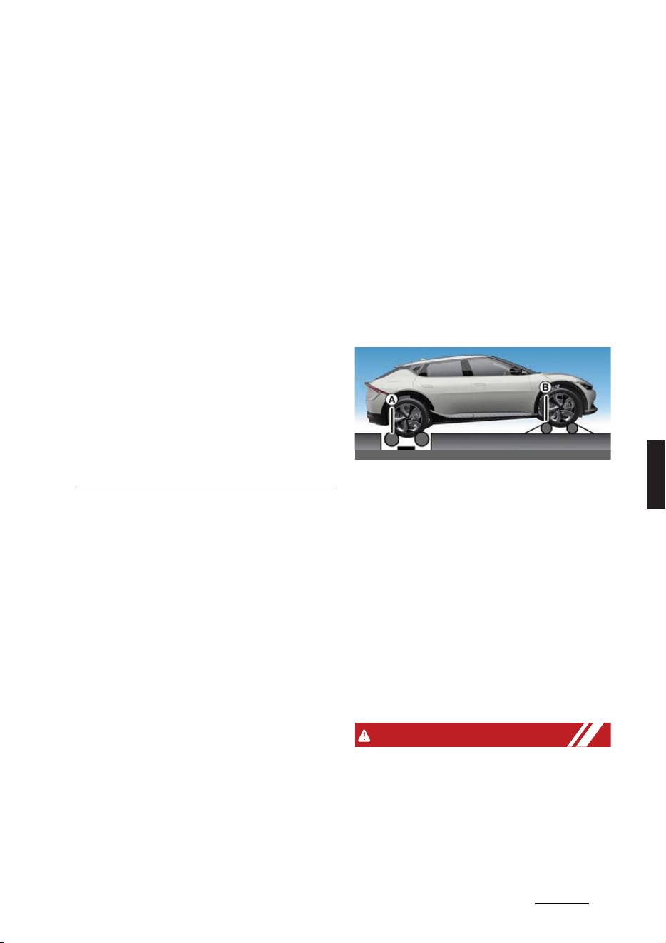
41
6
6
Driving your vehicle All wheel drive (4WD)
僅 When the vehicle is stuck in snow,
sand or mud, place a non-slip material
under the drive wheels to provide
traction OR slowly spin the wheels in
forward and reverse directions which
causes a rocking motion that may free
the vehicle.
僅 When putting the tire chains to the
tire, be sure to attach the chain to the
two rear wheels. In this case, drive
below 30 km/h (20 mph) and mini
-
mize the driving distance. High-speed
or long-term driving with putting the
tire chains may cause malfunction or
damage to the four-wheel drive.
僅 If tire chains must be used, use fabric
snow chain and install the tire chain
after reviewing the instructions pro
-
vided with the tire chains. For more
information on Snow Tires and Tire
Chains, refer to "Akstur að vetri til" on
page B-2.
Emergency precautions
Tires
When replacing the tires, be sure to
equip all four tires with the tire and
wheel of the same size, type, tread,
brand and load-carrying capacity.
In case of emergency such as tire punc
-
ture, repair it using TMK (Tire Mobility
Kit) for temporary use. Afterwards, have
the tire be inspected by an authorized
Kia dealer/service partner.
Towing
4WD vehicles must be towed with a
wheel lift and dollies or flatbed equip
-
ment with all the wheels off the ground.
For more information, refer to "Towing"
on page 7-15.
Vehicle inspection
僅 When the vehicle is on a car lift, do not
operate the front and rear wheels
separately. All four wheels should be
operated.
僅 Never engage the parking brake while
running the vehicle on a car lift. This
may damage the 4WD system.
Dynamometer testing
A 4WD vehicle must be tested on a spe
-
cial four wheel chassis dynamometer.
If a 2WD roll tester must be used, per
-
form the following procedure.
僅 A: Roll tester (Speedometer)
僅 B: Temporary free roller
Operation
1. Check the tire pressures recom
-
mended for your vehicle.
2. Place the rear wheels on the roll tester
for a speedometer test as shown in
the illustration.
3. Release the parking brake.
4. Place the front wheels on the tempo
-
rary free roller as shown in the illustra
-
tion.
WARNING
僅 Do not use tire and wheel with differ
-
ent size and type from the one origi
-
nally installed on your vehicle. It can
affect the safety and performance of
your vehicle, which could lead to
steering failure or rollover causing
serious injury.
OCV061004L
Driving your vehicle
426
Active air flap
僅 Never start or run the vehicle while a
4WD vehicle is raised on a jack.The
vehicle can slip or roll off of a jack
causing serious injury or death to you
or those nearby.
僅 Keep away from the front of the vehi
-
cle while the vehicle is in gear on the
dynamometer. The vehicle can jump
forward and cause serious injury or
death.
Active air flap
Active air flap system controls the air
flap below the front bumper to cool the
vehicle parts and improve energy effi
-
ciency.
Active air flap malfunction
A:
Check the active air flap system
The active air flap system may not oper
-
ate normally if the air flap is temporarily
opened due to foreign factors or if the
controller is contaminated by snow or
rain, etc.
When the message is popped up on the
display, stop the vehicle in a safe place
and check the status of the air flap.
Start the vehicle after performing the
necessary work like foreign matter
removal and waiting 10 minutes. If the
pop-up remains up, have the vehicle
inspected by a professional workshop.
Kia recommends visiting an authorized
Kia dealer/service partner.
CAUTION
僅 Regardless of the pop-up, if the air
flaps aren't in the same position, stop
the vehicle and wait for 10 minutes
and start the vehicle and inspect the
air flap.
OCV041202L
OCV041192L
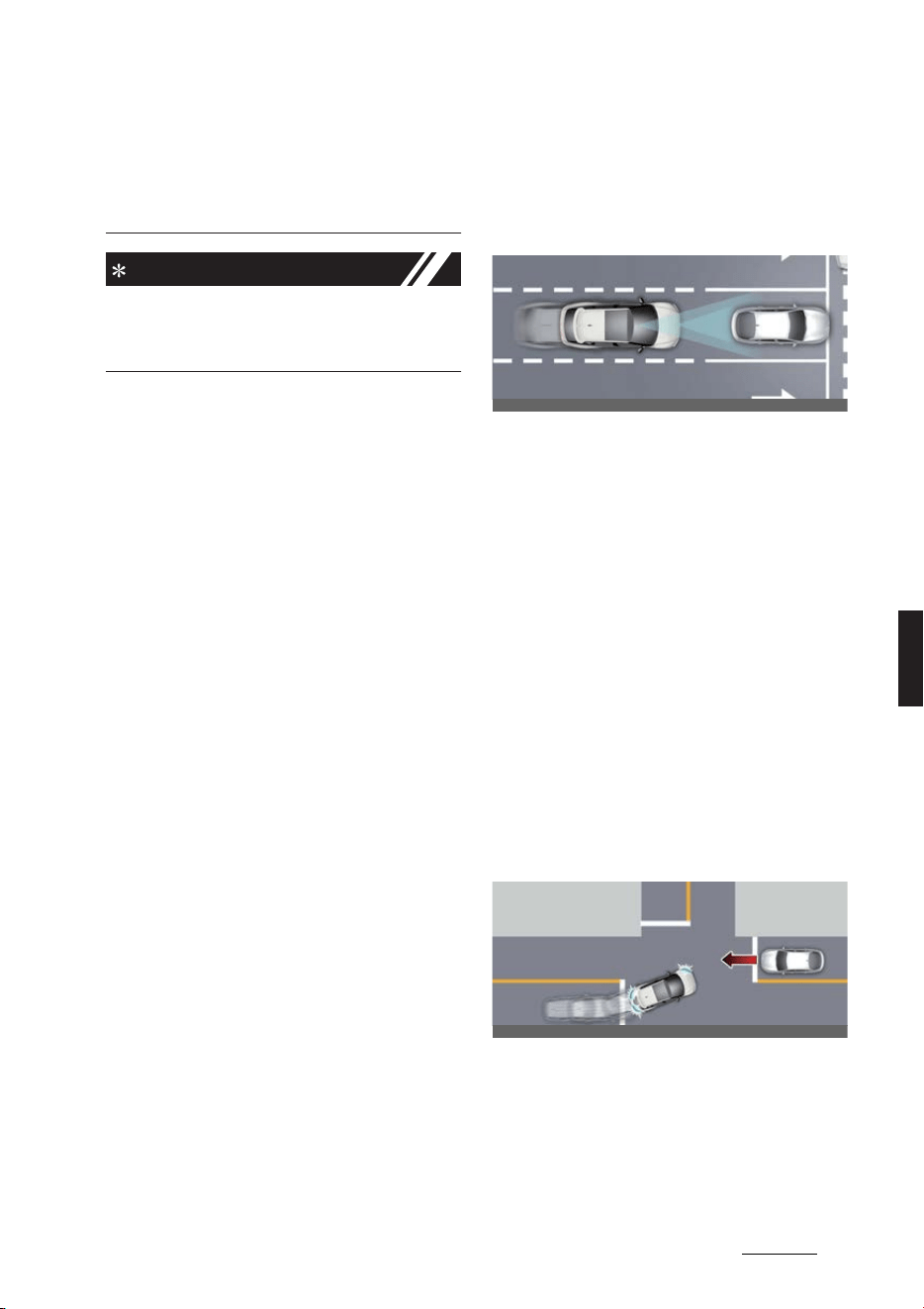
43
6
6
Driving your vehicle Forward Collision-Avoidance Assist (FCA)
僅 The active air flap system is actuated
by motors. Do not disturb actuation or
apply force excessively. It may cause
failure.
NOTICE
Active air flap system could be activate
regardless of the vehicle condi
-
tion.(Parking, driving, charging, etc.)
Forward Collision-Avoidance
Assist (FCA) (if equipped)
Basic function
Forward Collision-Avoidance Assist is
designed to help detect and monitor the
vehicle ahead or help detect a pedes
-
trian or cyclist in the roadway and warn
the driver that a collision is imminent
with a warning message and an audible
warning, apply emergency braking.
In addition, if equipped with front corner
radars, when driving at high speeds, For
-
ward Collision-Avoidance Assist will help
detect vehicles in front and adjacent
lanes. If a collision is imminent when
changing lanes, Forward Collision-
Avoidance Assist will apply emergency
braking to help prevent a collision (if
equipped).
Junction Turning function
Junction Turning function will help avoid
a collision with an oncoming vehicle in
an adjacent lane when turning left (left-
hand drive) or right (right-hand drive) at
a crossroad with the turn signal on by
applying emergency braking.
OCV051019L
OCV051020L
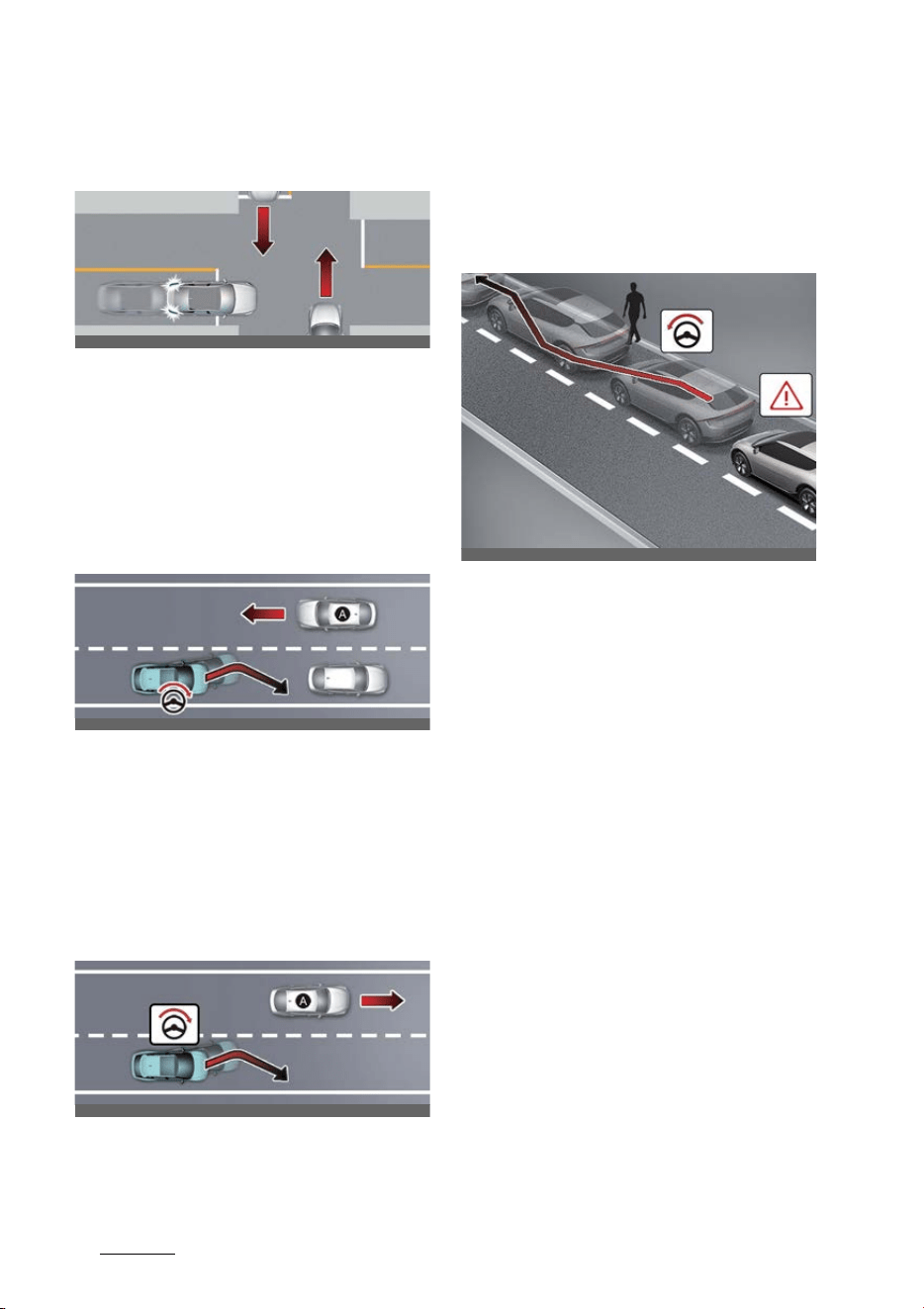
Driving your vehicle
446
Forward Collision-Avoidance Assist (FCA)
Junction Crossing function (if
equipped)
Junction Crossing function will help
avoid a collision with oncoming vehicles
on the left or right side when crossing an
intersection by applying emergency
braking.
Lane-Change Oncoming function
(if equipped)
[A]: Oncoming vehicle
Lane-Change Oncoming function will
help avoid a collision with an oncoming
vehicle when changing lanes by assist
-
ing the driver's steering.
Lane-Change Side function (if
equipped)
[A]: Front-side vehicle
Lane-Change Side function will help
avoid a collision with the vehicle ahead
in the next lane when changing lanes by
assisting the driver's steering.
Evasive Steering Assist function
(if equipped)
僅 Driver steering assist
Evasive Steering Assist function will
help avoid a collision with a vehicle,
pedestrian or cyclist ahead in the
same lane. When a risk of collision is
detected, Evasive Steering Assist
function will warn the driver and if the
driver steers to avoid collision it will
assist the driver's steering.
僅 Evasive steering assist
Evasive Steering Assist function helps
avoid a collision with a pedestrian or
cyclist ahead in the same lane. When
a risk of collision is detected, Evasive
Steering Assist function will warn the
driver and if there is space to avoid
collision in the lane, it will assist the
driver's steering.
OCV051232L
OCV051021L
OCV051022L
OCV051023L
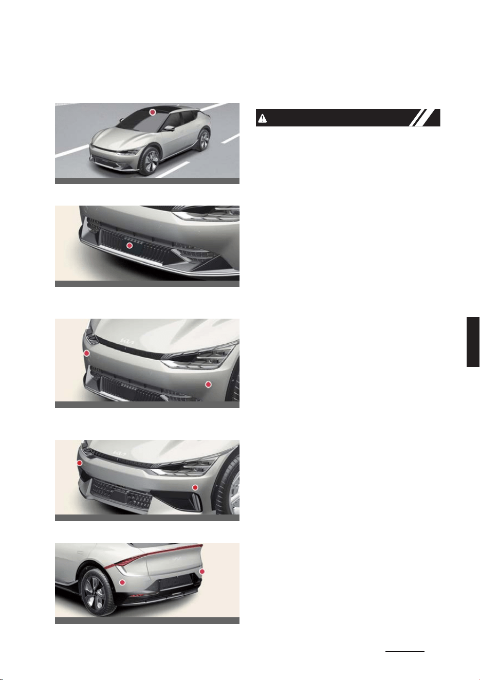
45
6
6
Driving your vehicle Forward Collision-Avoidance Assist (FCA)
Detecting sensor
Front view camera
Front radar
Front corner radar (Type A) (if
equipped)
Front corner radar (Type B) (if
equipped)
Rear corner radar (if equipped)
Refer to the picture above for the
detailed location of the detecting sen
-
sors.
CAUTION
Take the following precautions to main
-
tain optimal performance of the detect
-
ing sensor:
僅 Never disassemble the detecting sen
-
sor or sensor assembly, or apply any
impact on it.
僅 If the detecting sensors have been
replaced or repaired, have the vehicle
inspected by a professional workshop.
Kia recommends visiting an autho
-
rized Kia dealer/service partner.
僅 Never install any accessories or stick
-
ers on the front windshield, or tint the
front windshield.
僅 Pay extreme caution to keep the front
view camera dry.
僅 Never place any reflective objects (i.e.
white paper, mirror) over the dash
-
board.
僅 Do not apply license plate frame or
objects, such as a bumper sticker, film
or a bumper guard, near the front
radar cover.
僅 Always keep the front radar and cover
clean and free of dirt and debris.
Use only a soft cloth to wash the vehi
-
cle. Do not spray pressurized water
directly on the sensor or sensor cover.
僅 If unnecessary force has been applied
to the radar or around the radar, For
-
ward Collision-Avoidance Assist may
not properly operate even though a
warning message does not appear on
the cluster. Have the vehicle
inspected by a professional workshop.
Kia recommends visiting an autho
-
rized Kia dealer/service partner.
OCV051017L
OCV051005L
OCV051024L
OCVGT052282L
OCV051025L

Driving your vehicle
466
Forward Collision-Avoidance Assist (FCA)
僅 The genuine Kia front radar sensor
covers, bumper, front corner radar
and rear corner radar are parts with
quality and performance ensured. If
arbitrarily applying paint on or chang
-
ing the cover, Forward Collision-
Avoidance Assist may not function
properly.
Use only Kia Genuine Parts or those
of an equivalent standard with proven
quality and performance to repair or
replace the radar sensor covers.
僅 Vehicles equipped with front corner
radar and/or rear corner radar
- Do not apply license plate frame or
objects, such as a bumper sticker,
film or a bumper guard, near the
front corner radar or rear corner
radar.
- The function may not work prop
-
erly when the bumper has been
replaced, or the surroundings of
the front corner radar or rear cor
-
ner radar has been damaged or
paint has been applied.
- If a trailer, carrier, etc. is installed, it
may adversely affect the perfor
-
mance of the rear corner radar or
Forward Collision-Avoidance Assist
may not operate properly.
Forward Collision-Avoidance
Assist settings
Forward Safety
A:
Driver assistance
1 Forward safety
2 Active assist
3 Warning only
4 Off
With the vehicle on, select
Settings
→
Vehicle
→
Driver assistance
→
For
-
ward safety
from the infotainment sys
-
tem screen to set whether or not to use
each function.
僅
Active assist
: Forward Collision-
Avoidance Assist will warn the driver
with a warning message, an audible
warning and steering wheel vibration
depending on the collision risk levels.
Braking assist or steering assist (if
equipped) will be applied depending
on the collision risk.
僅
Warning only
: Forward Collision-
Avoidance Assist will warn the driver
with a warning message, an audible
warning and steering wheel vibration
depending on the collision risk levels.
Braking and steering (if equipped) will
not be assisted. The driver must apply
the brake pedal or steer the vehicle if
necessary.
僅
Off
: Forward Collision-Avoidance
Assist will turn off. The warning light
( ) will illuminate on the cluster.
The driver can monitor Forward Colli
-
sion-Avoidance Assist On/Off status
from the Settings menu. If the warning
light ( ) remains On when Forward Col
-
lision-Avoidance Assist is On, have the
vehicle inspected by a professional
workshop. Kia recommends visiting an
authorized Kia dealer/service partner.
OCV041563L
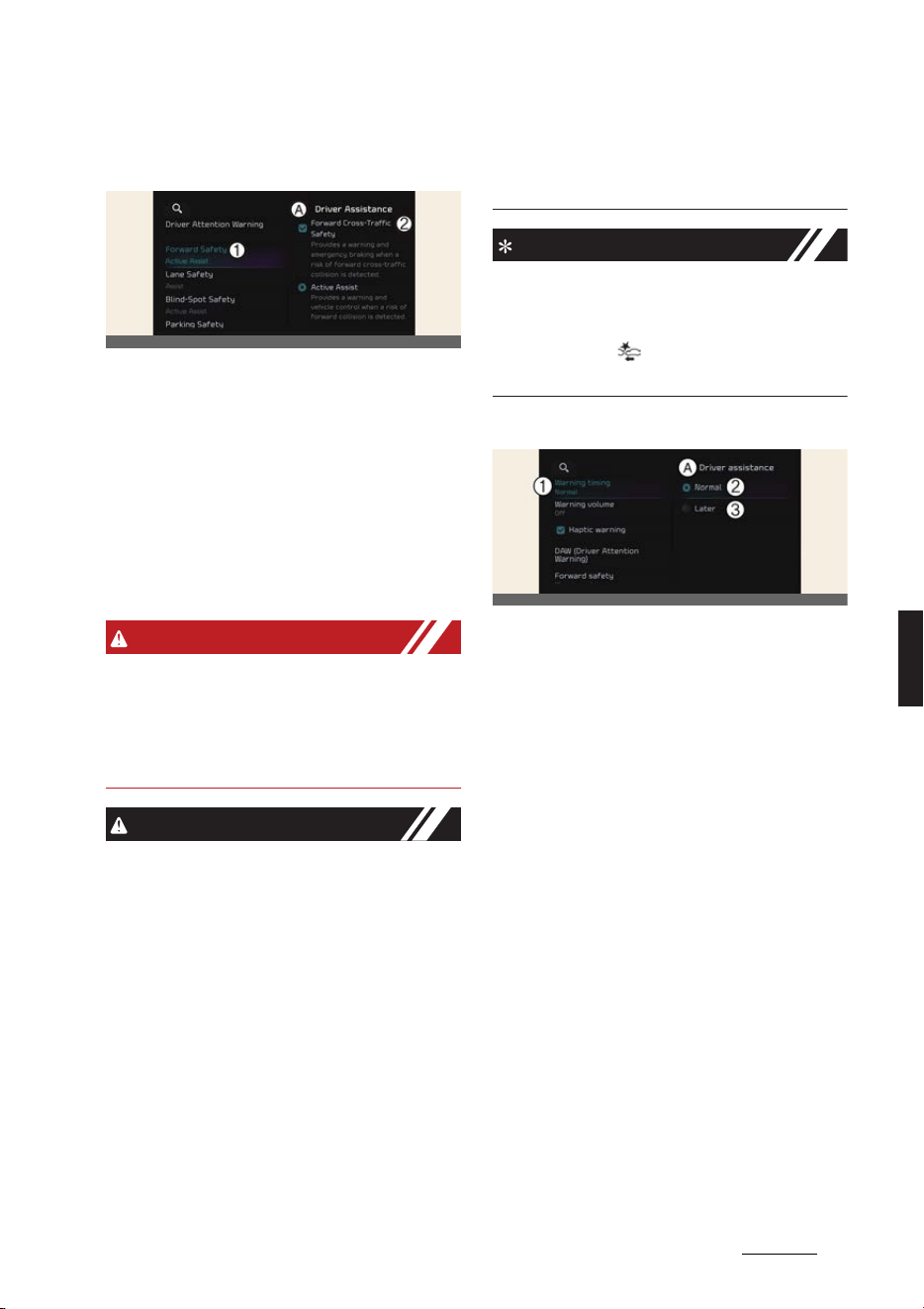
47
6
6
Driving your vehicle Forward Collision-Avoidance Assist (FCA)
Forward Cross-Traffic Safety (if
equipped)
A:
Driver assistance
1 Forward safety
2 Fwd. cross-traffic safety
With the vehicle on, select
Settings
→
Vehicle
→
Driver assistance
→
For
-
ward safety
→
Fwd. cross-traffic
safety
from the infotainment system
screen to turn on Junction Crossing
function and deselect to turn off the
function.
WARNING
When the vehicle is restarted, Forward
Collision-Avoidance Assist will always
turn on. However, if
Off
is selected, the
driver should always be aware of the
surroundings and drive safely.
CAUTION
僅If
Warning only
is selected, braking
and steering (if equipped) is not
assisted.
僅 The settings for Forward Safety
include 'Basic function' and 'Junction
Turning', ‘Lane-Change Oncoming',
'Lane-Change Side' and 'Evasive
Steering Assist' (if equipped).
僅 If Forward Safety is set to
Off
, Junc
-
tion Crossing function will not operate
even when
Fwd. cross-traffic safety
(if equipped) is selected.
僅 Steering wheel vibration can be
turned on or off. Select or deselect
Settings
→
Vehicle
→
Driver assis
-
tance
→
Haptic warning
from the
infotainment system screen.
NOTICE
Forward Collision-Avoidance Assist will
turn off when ESC is turned off by press
-
ing and holding the ESC OFF button. The
warning light ( ) will illuminate on the
cluster.
Warning timing
A:
Driver assistance
1 Warning timing
2 Normal
3 Late
With the vehicle on, select
Settings
→
Vehicle
→
Driver assistance
→
Warn
-
ing timing
from the infotainment sys
-
tem screen to change the initial warning
activation time for Forward Collision-
Avoidance Assist.
僅
Normal
: Use in a normal driving envi
-
ronment. If the function operates too
sensitively, set to the warning timing
to
Late
.
僅
Late
: The warning timing will be slow
OCV041564L
OCVGT042587L
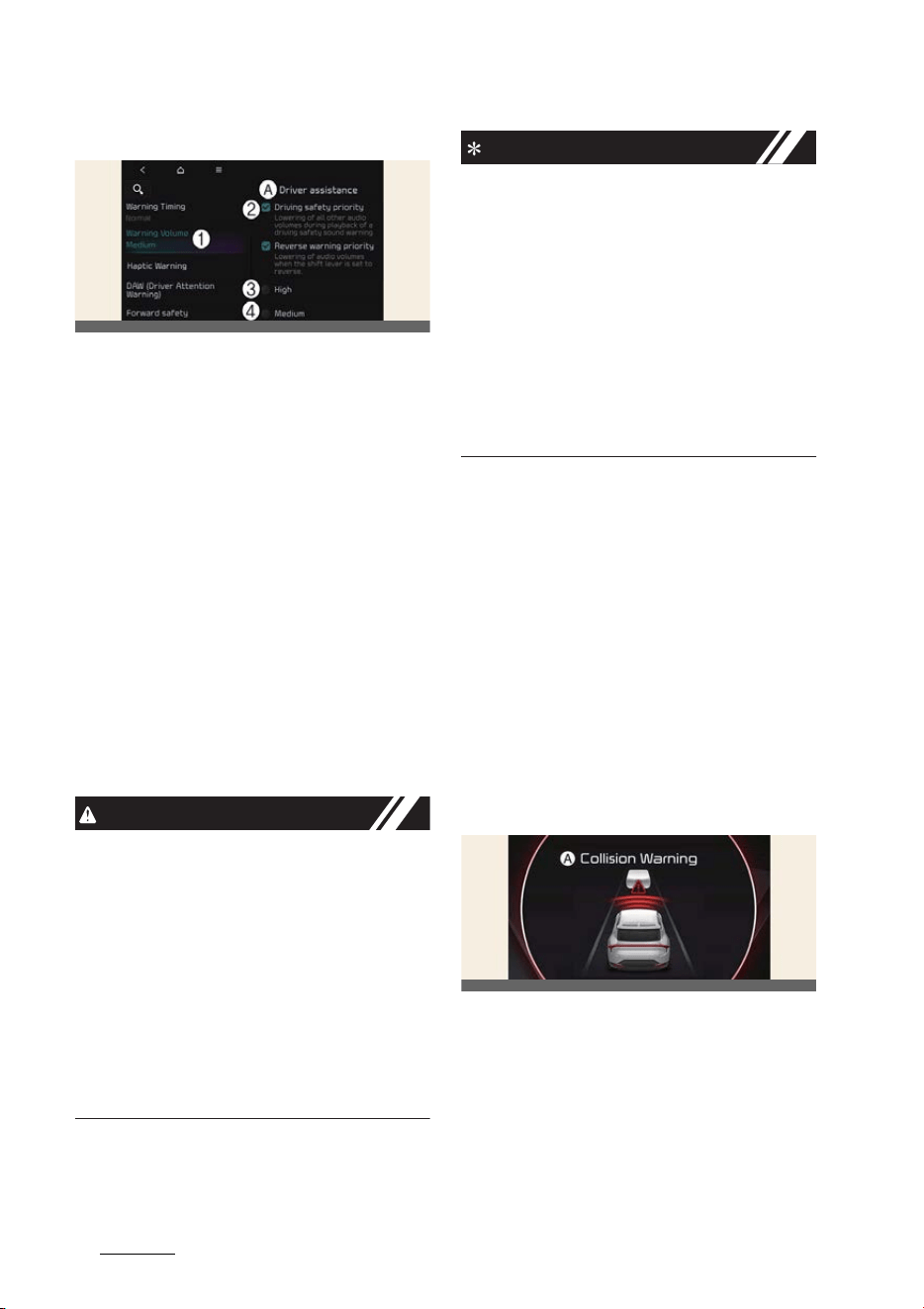
Driving your vehicle
486
Forward Collision-Avoidance Assist (FCA)
Warning volume
A:
Driver assistance
1 Warning volume
2 Driving safety priority
3 High
4 Medium
5 Low
6 Off
With the vehicle on, Settings
→
Vehi
-
cle
→
Driver assistance
→
Driving
safety
→
Warning volume
on the info
-
tainment system to change the Warning
volume to adjust the Warning volume
levels;
High
,
Medium
,
Low
or
Off
.
If
Driving safety priority
is selected, the
audio volume will temporarily decrease
to warn the driver with the audible warn
-
ing for safe driving.
CAUTION
僅 The setting of the Warning Timing
and Warning Volume applies to all
functions of Forward Collision-Avoid
-
ance Assist.
僅Even though
Normal
is selected for
Warning Timing, if the front vehicle
suddenly stops, the warning may
seem late.
僅 Select
Later
for Warning Timing when
traffic is light and when driving speed
is slow.
NOTICE
僅 If the vehicle is restarted, Warning vol
-
ume will maintain the last setting.
僅If
Off
is selected, the Warning volume
of Forward Collision-Avoidance Assist
will not turn off, but the volume will
sound as
Low
.
僅If
Off
is selected, steering wheel
vibration will not turn off.
僅 If you change the Warning volume,
the Warning volume of other Driver
Assistance systems may change.
Forward Collision-Avoidance
Assist operation
Basic function
Warning and control
The basic function for Forward Collision-
Avoidance Assist is warned and con
-
trolled by the following level.
僅 Collision Warning
僅Emergency Braking
僅 Stopping vehicle and ending brake
control
Collision Warning
A:
Collision Warning
The warning message, an audible warn
-
ing and the steering wheel will vibrate to
warn the driver of a collision.
Collision Warning will be activated in fol
-
lowing conditions.
僅 Vehicle: Your vehicle speed is approx
-
imately 10~200 km/h (6~124 mph)
OCVGT042562L
OCV051116L
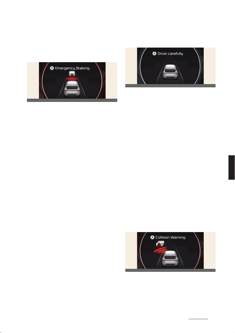
49
6
6
Driving your vehicle Forward Collision-Avoidance Assist (FCA)
僅 Pedestrian or cyclist: Your vehicle
speed is approximately 10~85 km/h
(6~53 mph)
Emergency braking
A:
Emergency braking
The warning message, an audible warn
-
ing and the steering wheel will vibrate to
warn the driver that emergency braking
will be assisted. The brake assist will be
activated and it helps avoiding collision
of a vehicle, pedestrian and cyclist.
Emergency Braking will be activated in
following conditions depending on the
target and the level of risk.
僅 Vehicle (weak braking): Your vehicle
speed is approximately 10~200 km/h
(6~124 mph)
僅 Vehicle (strong braking): Your vehicle
speed is approximately 10~85 km/h
(6~53 mph)
僅 If equipped with front corner radar,
the function judges that avoiding a
collision is difficult even by changing
the driving lane, it will operate when
your vehicle speed is between
approximately 10~100 km/h (6~62
mph).
僅 The function operation range may
decrease due to the front traffic con
-
dition or the surroundings of the vehi
-
cle.
僅 Pedestrian or cyclist: Your vehicle
speed is approximately 10~65 km/h
(6~40 mph)
Stopping vehicle and ending
brake control
A:
Drive carefully
When the vehicle is stopped due to
emergency braking, the warning mes
-
sage will appear on the cluster.
For your safety, the driver should
depress the brake pedal immediately
and check the surroundings.
僅 Brake control will end after the vehicle
is stopped by emergency braking for
approximately 2 seconds.
Junction Turning function
Warning and control
The basic function for Junction Turning
function is warned and controlled by the
following level.
僅 Collision Warning
僅Emergency Braking
僅 Stopping vehicle and ending brake
control
Collision Warning
A:
Collision Warning
The warning message, an audible warn
-
ing and the steering wheel will vibrate to
warn the driver of a collision.
OCV051117L
OCV051118L
OCV051121L
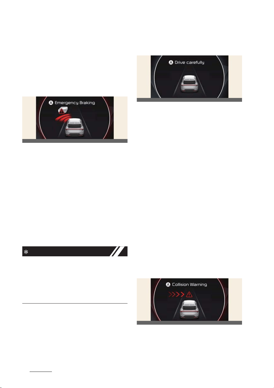
Driving your vehicle
506
Forward Collision-Avoidance Assist (FCA)
Collision Warning will be activated in fol
-
lowing conditions.
僅 Vehicle speed: Approximately 10~30
km/h (6~19 mph)
僅 Oncoming vehicle speed: Approxi
-
mately 30~70 km/h (19~44 mph)
Emergency braking
A:
Emergency braking
The warning message, an audible warn
-
ing and the steering wheel will vibrate to
warn the driver that emergency braking
will be assisted. The brake assist will be
activated and it helps avoiding collision
of a vehicle.
Emergency Braking will be activated in
following conditions.
僅 Vehicle speed: Approximately 10~30
km/h (6~19 mph)
僅 Oncoming vehicle speed: Approxi
-
mately 30~70 km/h (19~44 mph)
NOTICE
If the driver's seat is on the left side,
Junction Turning function will operate
only when the driver turns left. If the
driver's seat position is on right side, the
function will operate only when you turn
right.
Stopping vehicle and ending
brake control
A:
Drive carefully
When the vehicle is stopped due to
emergency braking, the warning mes
-
sage will appear on the cluster.
For your safety, the driver should
depress the brake pedal immediately
and check the surroundings.
僅 Brake control will end after the vehicle
is stopped by emergency braking for
approximately 2 seconds.
Junction Crossing function (if
equipped)
Warning and control
The basic function for Junction Crossing
function is warned and controlled by the
following level.
僅 Collision Warning
僅Emergency Braking
僅 Stopping vehicle and ending brake
control
Collision Warning
OCV051122L
OCV051118L
OCV051124L
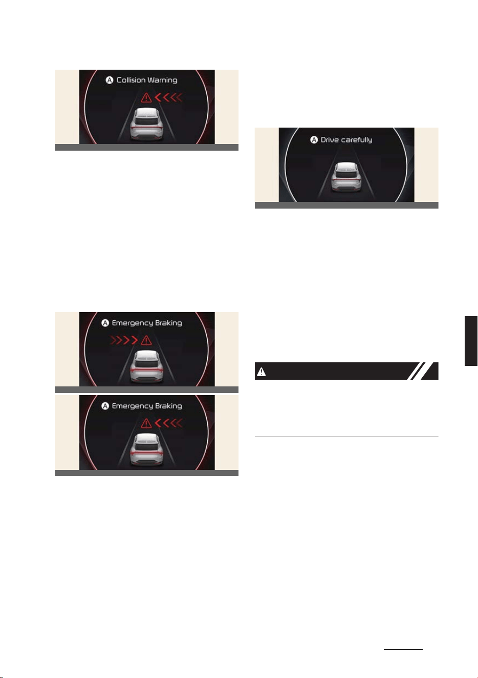
51
6
6
Driving your vehicle Forward Collision-Avoidance Assist (FCA)
A:
Collision Warning
The warning message, an audible warn
-
ing and the steering wheel will vibrate to
warn the driver of a collision.
Collision Warning will be activated in fol
-
lowing conditions.
僅 Vehicle speed: Approximately 10~30
km/h (6~19 mph)
僅 Crossing vehicle speed: Approxi
-
mately 10~60 km/h (6~37 mph)
Emergency braking
A:
Emergency braking
The warning message, an audible warn
-
ing and the steering wheel will vibrate to
warn the driver that emergency braking
will be assisted. The brake assist will be
activated and it helps avoiding collision
of a vehicle.
Emergency Braking will be activated in
following conditions.
僅 Vehicle speed: Approximately 10~30
km/h (6~19 mph)
僅 Crossing vehicle speed: Approxi
-
mately 10~20 km/h (6~12 mph)
Stopping vehicle and ending
brake control
A:
Drive carefully
When the vehicle is stopped due to
emergency braking, the
Drive carefully
warning message will appear on the
cluster.
For your safety, the driver should
depress the brake pedal immediately
and check the surroundings.
僅 Brake control will end after the vehicle
is stopped by emergency braking for
approximately 2 seconds.
CAUTION
If the collision angle with the crossing
vehicle is beyond a certain range, Junc
-
tion Crossing Warning and control may
be late or may not operate.
Lane-Change Oncoming function
(if equipped)
Warning and control
The basic function for Lane-Change
Oncoming function is warned and con
-
trolled by the following level.
僅 Collision Warning
僅 Emergency Steering
OCV051123L
OCV051126L
OCV051125L
OCV051118L
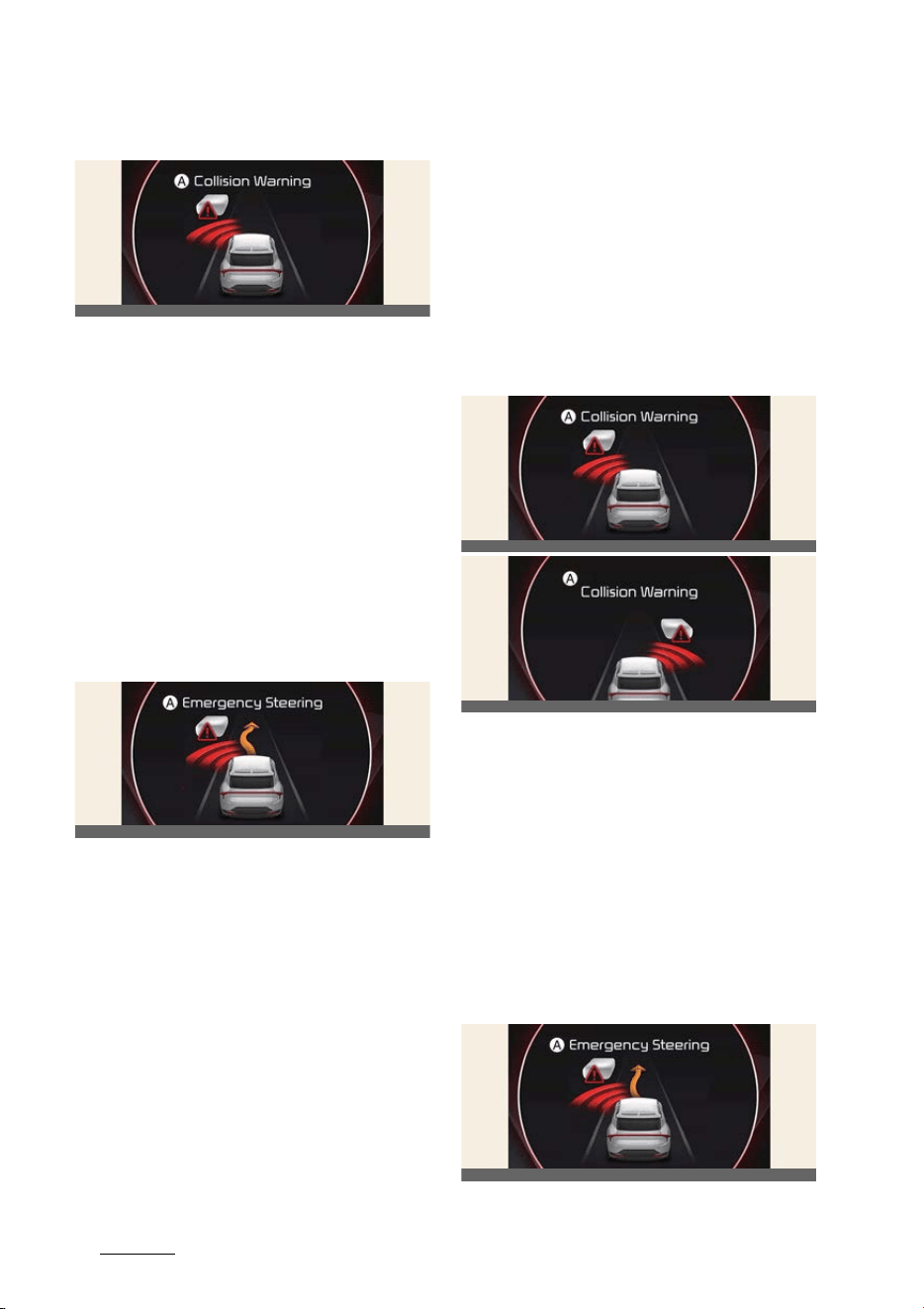
Driving your vehicle
526
Forward Collision-Avoidance Assist (FCA)
Collision Warning
A:
Collision Warning
The warning message, an audible warn
-
ing and the steering wheel will vibrate to
warn the driver of a collision.
Collision Warning will be activated in fol
-
lowing conditions.
僅 Vehicle speed: Approximately 40~145
km/h (25~90 mph)
僅 Oncoming vehicle speed: Approxi
-
mately above 10 km/h (6 mph)
僅 Relative speed: Approximately below
200 km/h (124 mph)
Emergency Steering
A:
Emergency Steering
To warn the driver that emergency
steering will be assisted, the warning
message will appear on the cluster, an
audible warning will sound and the
steering wheel will vibrate.
Emergency Steering will be activated in
following conditions.
僅 Vehicle speed: Approximately 40~145
km/h (25~90 mph)
僅 Oncoming vehicle speed: Approxi
-
mately above 10 km/h (6 mph)
僅 Relative speed: Approximately below
200 km/h (124 mph)
Lane-Change Side function (if
equipped)
Warning and control
The basic function for Lane-Change
Oncoming function is warned and con
-
trolled by the following level.
僅 Collision Warning
僅 Emergency Steering
Collision Warning
A:
Collision Warning
To warn the driver of a collision, the
warning message will appear on the
cluster, an audible warning will sound
and the steering wheel will vibrate.
Emergency Steering will be activated in
following conditions.
僅 Vehicle speed: 40~145 km/h (25~90
mph)
僅 Front-side vehicle: Driving
Emergency Steering
OCV051121L
OCV051127L
OCV051121L
OCV041193L
OCV051129L
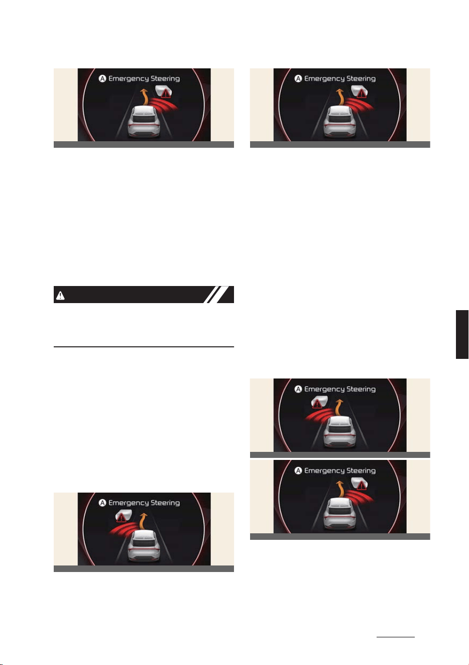
53
6
6
Driving your vehicle Forward Collision-Avoidance Assist (FCA)
A:
Emergency Steering
To warn the driver that emergency
steering will be assisted, the warning
message will appear on the cluster, an
audible warning will sound and the
steering wheel will vibrate.
Emergency Steering will be activated in
following conditions.
僅 Vehicle speed: Approximately 40~145
km/h (25~90 mph)
CAUTION
Lane-Change Side function does not
operate if the oncoming vehicle from the
front side is stopped.
Evasive Steering Assist function
(if equipped)
Warning and control
The basic function for Lane-Change
Oncoming function is warned and con
-
trolled by the following level.
僅 Emergency Steering
Emergency Steering (Driver
steering assist)
A:
Emergency Steering
To warn the driver that emergency
steering will be assisted, the warning
message will appear on the cluster, an
audible warning will sound and the
steering wheel will vibrate. If there is a
risk of collision with a vehicle, pedestrian
and cyclist in front, the steering will be
assisted to help prevent collision when
the driver steers the vehicle to avoid col
-
lision.
Emergency Steering will be activated in
following conditions.
僅 Vehicle speed: 40~85 km/h (25~53
mph)
Emergency Steering (Evasive
steering assist)
A:
Emergency Steering
To warn the driver that emergency
steering will be assisted, the warning
message will appear on the cluster, an
audible warning will sound and the
OCV051128L
OCV051129L
OCV051128L
OCV051129L
OCV051128L

Driving your vehicle
546
Forward Collision-Avoidance Assist (FCA)
steering wheel will vibrate. If there is
high risk of collision with a pedestrian
and cyclist in front, and the vehicle
speed to operate emergency braking is
within the operation range, the steering
will be assisted to help prevent collision
when there is space to avoid collision in
the driving lane.
Emergency Steering will be activated in
following conditions.
僅 Vehicle speed: 65~75 km/h (40~47
mph)
CAUTION
僅 The steering wheel may turn auto
-
matically when emergency steering is
operating.
僅 Emergency steering will automati
-
cally cancel when risk factors disap
-
pear. If necessary, the driver must
steer the vehicle.
僅 Emergency steering may not operate
or may cancel during operation if the
steering wheel is held tight or steered
in the opposite direction.
僅 When steering is assisted to avoid col
-
lision with a vehicle, pedestrian and
cyclist, Evasive steering assist will be
canceled if collisions with other
objects (vehicles, pedestrians, or
cyclists) are expected.
僅 Evasive steering assist may not oper
-
ate if space to avoid collision in the
driving lane is insufficient.
NOTICE
For more details on warning messages,
refer to Collision Warning in "Basic Func
-
tion""Collision Warning" on page 6-48.
WARNING
僅 For your safety, change the Settings
after parking the vehicle at a safe
location.
僅With
Active Assist
or
Warning only
selected, when ESC is turned off by
pressing and holding the ESC OFF
button, Forward Collision-Avoidance
Assist will turn off automatically. In
this case, Forward Collision-Avoid
-
ance Assist cannot be set from the
Settings menu and the ( ) warning
light will illuminate on the cluster
which is normal. If ESC is turned on by
pressing the ESC OFF button again,
Forward Collision-Avoidance Assist
will maintain the last setting. Forward
Collision-Avoidance Assist does not
operate in all situations or cannot
avoid all collisions.
僅 The driver should hold the responsi
-
bility to control the vehicle. Do not
solely depend on Forward Collision-
Avoidance Assist. Rather, maintain a
safe braking distance, and if neces
-
sary, depress the brake pedal to
reduce driving speed or to stop the
vehicle.
僅 Never deliberately operate Forward
Collision-Avoidance Assist on people,
objects, etc. It may cause serious
injury or death.
僅 Forward Collision-Avoidance Assist
may not operate if the driver
depresses the brake pedal to avoid
collision.
僅 Depending on the road and driving
conditions, Forward Collision-Avoid
-
ance Assist may warn the driver late
or may not warn the driver.
僅 During Forward Collision-Avoidance
Assist operation, the vehicle may stop
suddenly injuring passengers and

55
6
6
Driving your vehicle Forward Collision-Avoidance Assist (FCA)
shifting loose objects. Always have the
seat belt on and keep loose objects
secured.
僅 If any other system's warning mes
-
sage is displayed or audible warning
is generated, Forward Collision-Avoid
-
ance Assist warning message may not
be displayed and audible warning
may not be generated.
僅 You may not hear the warning sound
of Forward Collision-Avoidance Assist
if the surrounding is noisy.
僅 Forward Collision-Avoidance Assist
may turn off or may not operate prop
-
erly or may operate unnecessarily
depending on the road conditions and
the surroundings.
僅 Even if there is a problem with For
-
ward Collision-Avoidance Assist, the
vehicle's basic braking performance
will operate normally.
僅 During emergency braking, braking
control by Forward Collision-Avoid
-
ance Assist will automatically cancel
when the driver excessively depresses
the accelerator pedal or sharply steers
the vehicle.
CAUTION
僅 Depending on the condition of the
vehicle, pedestrian and cyclist in front
and the surroundings or due to reduc
-
tion of the range to detect, the speed
range to operate Forward Collision-
Avoidance Assist may reduce. For
-
ward Collision-Avoidance Assist may
only warn the driver, or it may not
operate.
僅 Forward Collision-Avoidance Assist
will operate under certain conditions
by judging the risk level based on the
condition of the oncoming vehicle,
driving direction, speed and sur
-
roundings.
僅 If your driving speed is too high or the
speed difference with the other vehi
-
cle is large, Forward Collision-Avoid
-
ance Assist may be limited or may not
work.
僅 When a collision with a surrounding
vehicle is expected, Lane-Change
Oncoming, Lane-Change Side and
Evasive Steering Assist functions will
only warn the driver. (if equipped)
NOTICE
僅 When a collision is imminent, the For
-
ward Collision-Avoidance Assist may
assist the driver with brakes if the
driver fails to brake enough.
僅 The images or colors may be dis
-
played differently depending on the
specifications of the instrument clus
-
ter or theme.
Forward Collision-Avoidance
Assist malfunction and limitations
Forward Collision-Avoidance
Assist malfunction
A:
Check Forward Safety system
When Forward Collision-Avoidance
Assist is not working properly, the warn
-
ing message will appear, and the ( )
and ( ) warning lights will illuminate on
the cluster. Kia recommends visiting an
authorized Kia dealer/service partner.
OCV051119L
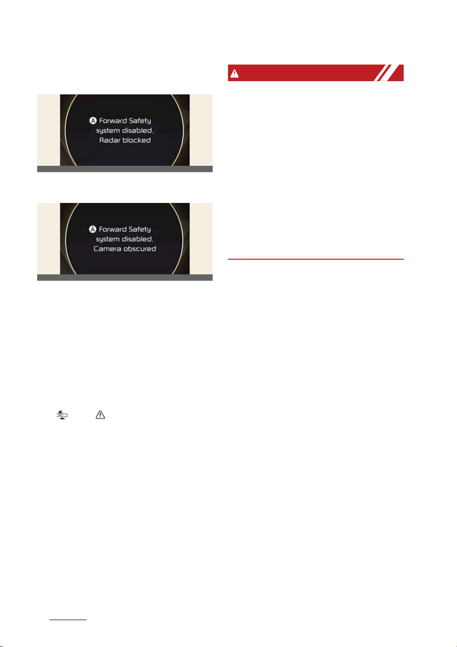
Driving your vehicle
566
Forward Collision-Avoidance Assist (FCA)
Forward Collision-Avoidance
Assist disabled
A:
Forward safety system disabled.
Radar blocked
A:
Forward safety system disabled.
Camera obscured
When the front windshield where the
front view camera is located, front radar
cover, bumper or sensor is covered with
foreign material, such as snow or rain, it
can reduce the detecting performance
and temporarily limit or disable Forward
Collision-Avoidance Assist.
If this occurs the warning message, and
the ( ) and ( ) warning lights will illu
-
minate on the cluster.
Forward Collision-Avoidance Assist will
operate normally when snow, rain or for
-
eign material is removed.
If Forward Collision-Avoidance Assist
does not operate normally after obstruc
-
tion (snow, rain, or foreign material) is
removed (including trailer, carrier, etc.
from the rear bumper), have the vehicle
inspected by a professional workshop.
Kia recommends visiting an authorized
Kia dealer/service partner.
WARNING
僅 Even though the warning message or
warning light does not appear on the
cluster, Forward Collision-Avoidance
Assist may not properly operate.
僅 Forward Collision-Avoidance Assist
may not properly operate in an area
(e.g. open terrain), where any sub
-
stance are not detected after turning
ON the vehicle.
僅 Forward Collision-Avoidance Assist
may not operate normally if the vehi
-
cle is turned off and restarted with the
front radar cover, bumper or sensor
covered.
Limitations of Forward Collision-
Avoidance Assist
Forward Collision-Avoidance Assist may
not operate normally, or it may operate
unexpectedly under the following cir
-
cumstances:
僅 The detecting sensor or the surround
-
ings are contaminated or damaged
僅 The temperature around the front
view camera is high or low due to sur
-
rounding environment
僅 The camera lens is contaminated due
to tinted, filmed or coated windshield,
damaged glass, or sticky foreign
material (sticker, bug, etc.) on the
glass
僅 Moisture is not removed or frozen on
the windshield
僅Washer fluid is continuously sprayed,
or the wiper is on
僅 Driving in heavy rain or snow, or thick
fog
僅 The field of view of the front view
camera is obstructed by sun glare
OCV051130L
OCV051120L

57
6
6
Driving your vehicle Forward Collision-Avoidance Assist (FCA)
僅 Street light or light from an oncoming
vehicle is reflected on the wet road
surface, such as a puddle on the road
僅 An object is placed on the dashboard
僅 Your vehicle is being towed
僅 The surrounding is very bright
僅 The surrounding is very dark, such as
in a tunnel, etc.
僅 The brightness changes suddenly, for
example when entering or exiting a
tunnel
僅 The brightness outside is low, and the
headlamps are not on or are not
bright
僅 Driving through steam, smoke or
shadow
僅 Only part of the vehicle, pedestrian or
cyclist is detected
僅 The vehicle in front is a bus, heavy
truck, truck with a unusually shaped
luggage, trailer, etc.
僅 The vehicle in front has no tail lights,
tail lights are located unusually, etc.
僅 The brightness outside is low, and the
tail lamps are not on or are not bright
僅 The rear of the front vehicle is small or
the vehicle does not look normal, such
as when the vehicle is tilted, over
-
turned, or the side of the vehicle is vis
-
ible, etc.
僅 The front vehicle's ground clearance
is low or high
僅 A vehicle, pedestrian or cyclist sud
-
denly cuts in front
僅 The bumper around the front radar is
impacted, damaged or the front radar
is out of position
僅 The temperature around the front
radar is high or low
僅 Driving through a tunnel or iron
bridge
僅 Driving in large areas where there are
few vehicles or structures (i.e. desert,
meadow, suburb, etc.)
僅 Driving near areas containing metal
substances, such as a construction
zone, railroad, etc.
僅 A material is near that reflects very
well on the front radar, such as a
guardrail, nearby vehicle, etc.
僅 The cyclist in front is on a bicycle
made of material that does not reflect
on the front radar
僅 The vehicle in front is detected late
僅 The vehicle in front is suddenly
blocked by a obstacle
僅 The vehicle in front suddenly changes
lane or suddenly reduces speed
僅 The vehicle in front is bent out of
shape
僅 The vehicle in front is covered with
snow
僅 You are departing or returning to the
lane
僅 Unstable driving
僅 You are on a roundabout and the
vehicle in front is not detected
僅 You are continuously driving in a cir
-
cle
僅 The vehicle in front has an unusual
shape
僅 The vehicle in front is driving uphill or
downhill
僅 The pedestrian or cyclist is not fully
detected, for example, if the pedes
-
trian is leaning over or is not fully
walking upright
僅 The pedestrian or cyclist is wearing
clothing or equipment that makes it
difficult to detect as a pedestrian or
cyclist
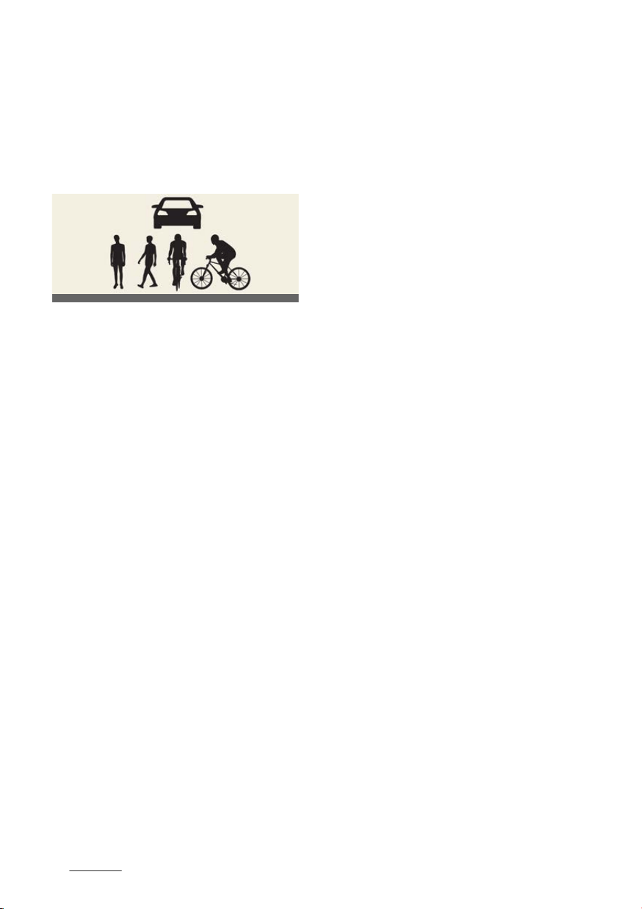
Driving your vehicle
586
Forward Collision-Avoidance Assist (FCA)
僅 The pedestrian or cyclist in front is
moving very quickly
The illustration above shows the image
the front view camera and front radar
will detect as a vehicle, pedestrian and
cyclist.
僅 The pedestrian or cyclist in front is
short or is posing a low posture
僅 The pedestrian or cyclist in front has
impaired mobility
僅 The pedestrian or cyclist in front is
moving intersected with the driving
direction
僅 There is a group of pedestrians,
cyclists or a large crowd in front
僅 The pedestrian or cyclist is wearing
clothing that easily blends into the
background, making it difficult to
detect
僅 The pedestrian or cyclist is difficult to
distinguish from the similar shaped
structure in the surroundings
僅 You are driving by a pedestrian,
cyclist, traffic signs, structures, etc.
near the intersection
僅 Driving in a parking lot
僅 Driving through a tollgate, construc
-
tion area, unpaved road, partial paved
road, uneven road, speed bumps, etc.
僅 Driving on an incline road, curved
road, etc.
僅 Driving through a roadside with trees
or streetlights
僅 The adverse road conditions cause
excessive vehicle vibrations while
driving
僅 Your vehicle height is low or high due
to heavy loads, abnormal tire pres
-
sure, etc.
僅 Driving through a narrow road where
trees or grass are overgrown
僅 There is interference by electromag
-
netic waves, such as driving in an area
with strong radio waves or electrical
noise
Junction Crossing, Lane-Change
Oncoming, Lane-Change Side,
Evasive Steering Assist function
(if equipped)
僅 The temperature around the front
corner radar or rear corner radar is
high or low
僅 A trailer or carrier is installed around
the rear corner radar
僅 The front corner radar or rear corner
radar is covered with snow, rain, dirt,
etc.
僅 The bumper around the front corner
radar or rear corner radar is covered
with objects, such as a bumper
sticker, bumper guard, bike rack, etc.
僅 The bumper around the front corner
radar or rear corner radar is impacted,
damaged or the radar is out of posi
-
tion
僅 The front corner radar or rear corner
radar is blocked by other vehicles,
walls or pillars
僅 Driving on a highway (or motorway)
ramp
僅 Driving on a road where the guardrail
or wall is in double structure
僅 The other vehicle drives very close
behind your vehicle, or the other vehi
-
OCV061029L
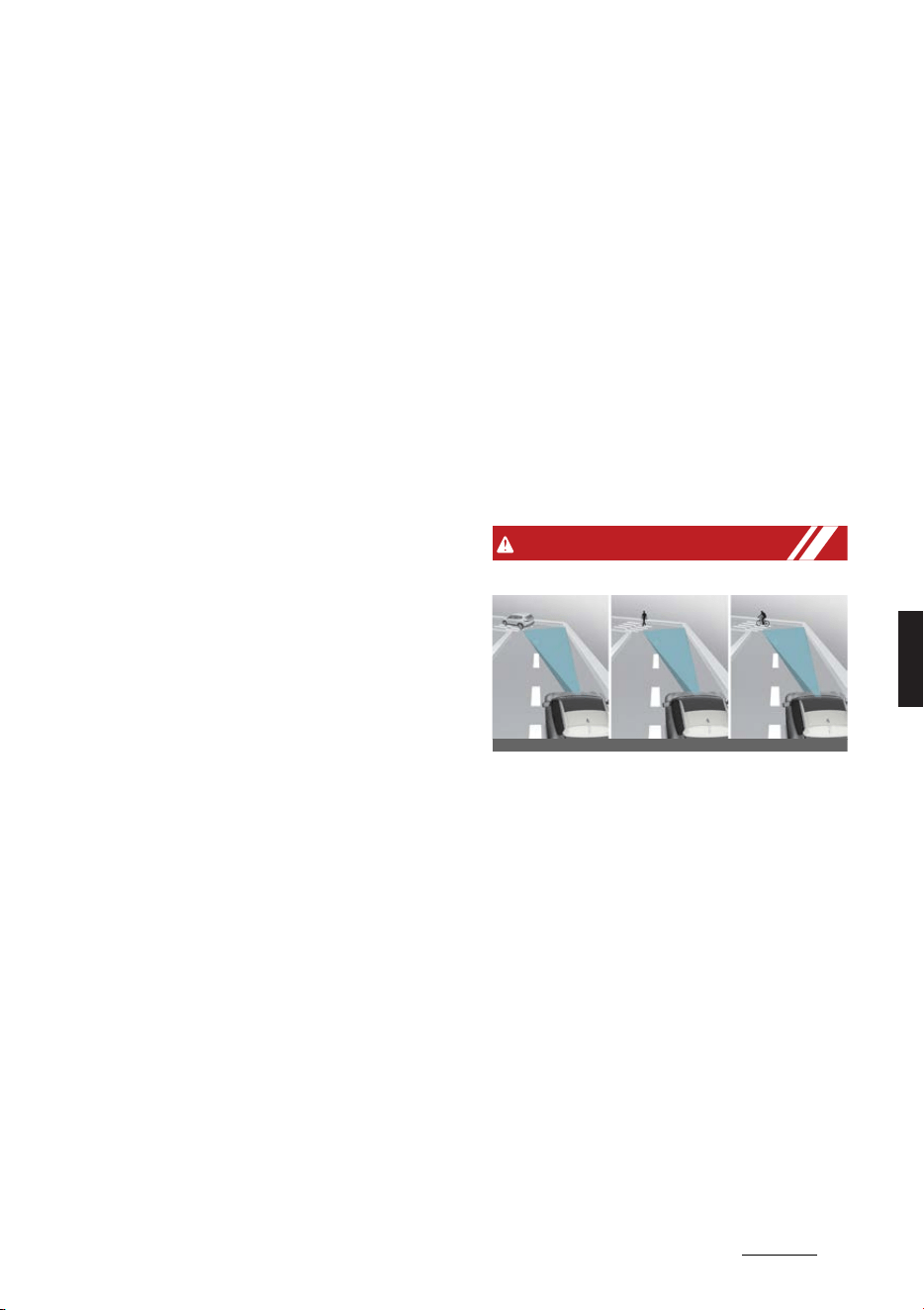
59
6
6
Driving your vehicle Forward Collision-Avoidance Assist (FCA)
cle passes by your vehicle in close
proximity
僅 The speed of the other vehicle is very
fast that it passes by your vehicle in a
short time
僅 Your vehicle passes by the other vehi
-
cle
僅 Your vehicle has started at the same
time as the vehicle next to you and
has accelerated
僅 The vehicle in the next lane moves
two lanes away from you, or when the
vehicle two lanes away moves to the
next lane from you
僅 A motorcycle or bicycle is detected
僅 A vehicle such as a flat trailer is
detected
僅 A big vehicle such as a bus or truck is
detected
僅 A small moving obstacle such as a
pedestrian, animal, shopping cart or a
baby stroller is detected
僅 A vehicle with low height such as a
sports car is detected
僅 The lane is difficult to see due to for
-
eign material, such as rain, snow,
dust, sand, oil and water puddles
僅 The color of the lane marking is not
distinguishable from the road
僅 There are markings on the road near
the lane or the markings on the road
looks similar to the lane markings
僅 The shadow is on the lane marking by
a median strip, trees, guardrail, noise
barriers, etc.
僅 The lane number increases or
decreases, or the lane markings are
crossing
僅 There are more than two lane mark
-
ings on the road
僅 The lane markings are complicated or
a structure substitutes for the lines,
such as a construction area
僅 There are road markings, such as zig
-
zag lanes, crosswalk markings and
road signs
僅 The lane suddenly disappears, such
as at the intersection
僅 The lane is very wide or narrow
僅 There is a curb or road edges without
a lane
僅 The vehicle in front is driving with one
side on the lane marking
僅 The distance to the front vehicle is
extremely short
WARNING
僅 Driving on a curved road
Forward Collision-Avoidance Assist
may not detect other vehicles, pedes
-
trians or cyclists in front of you on
curved roads adversely affecting the
performance of the sensors. This may
result in no warning, braking assist or
steering assist (if equipped) when
necessary.
When driving on a curved road, you
must maintain a safe braking dis
-
tance, and if necessary, steer the vehi
-
cle and depress the brake pedal to
reduce your driving speed in order to
maintain a safe distance.
OCV051029L_3
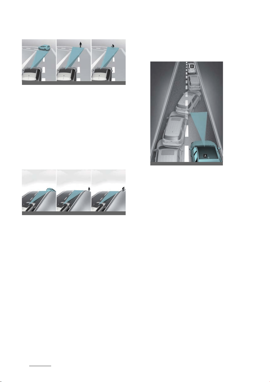
Driving your vehicle
606
Forward Collision-Avoidance Assist (FCA)
Forward Collision-Avoidance Assist
may detect a vehicle, pedestrian or
cyclist in the next lane or outside the
lane when driving on a curved road.
If this occurs, Forward Collision-Avoid
-
ance Assist may unnecessarily warn
the driver and control the brake or
steering wheel (if equipped). Always
check the traffic conditions around
the vehicle.
僅 Driving on an inclined road
Forward Collision-Avoidance Assist
may not detect other vehicles, pedes
-
trians or cyclists in front of you while
driving uphill or downhill, adversely
affecting the performance of the sen
-
sors.
This may result in unnecessary warn
-
ing, braking assist or steering assist (if
equipped) or no warning, braking
assist or steering assist (if equipped)
when necessary.
Also, vehicle speed may rapidly
decrease when a vehicle, pedestrian
or cyclist ahead is suddenly detected.
Always have your eyes on the road
while driving uphill or downhill and if
necessary, steer your vehicle and
depress the brake pedal to reduce
your driving speed in order to main
-
tain a safe distance.
僅 Changing lanes
[A]: Your vehicle, [B]: Lane changing
vehicle
When a vehicle moves into your lane
from an adjacent lane, it cannot be
detected by the sensor until it is in the
sensor's detection range. Forward
Collision-Avoidance Assist may not
immediately detect the vehicle when
the vehicle changes lanes abruptly. In
this case, you must maintain a safe
braking distance, and if necessary,
steer your vehicle and depress the
brake pedal to reduce your driving
speed in order to maintain a safe dis
-
tance.
OCV051030L_3
OCV051031L_3
OCV051238L
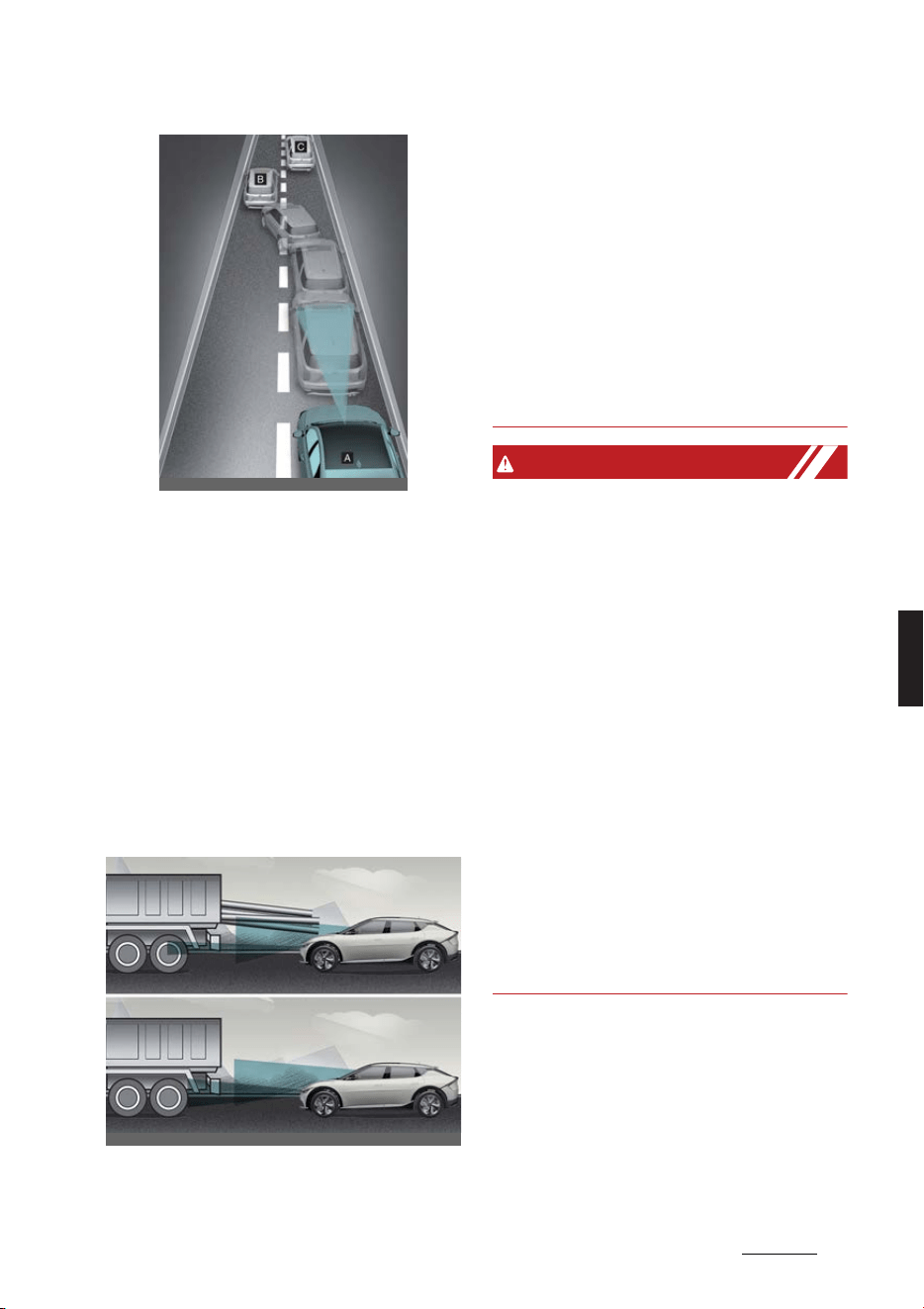
61
6
6
Driving your vehicle Forward Collision-Avoidance Assist (FCA)
[A]: Your vehicle, [B]: Lane changing
vehicle,
[C]: Same lane vehicle
When a vehicle in front of you merges
out of the lane, Forward Collision-
Avoidance Assist may not immedi
-
ately detect the vehicle that is now in
front of you. In this case, you must
maintain a safe braking distance, and
if necessary, steer your vehicle and
depress the brake pedal to reduce
your driving speed in order to main
-
tain a safe distance.
僅 Detecting a vehicle
If the vehicle in front of you has cargo
that extends rearward from the cab,
or when the vehicle in front of you has
higher ground clearance, additional
special attention is required. Forward
Collision-Avoidance Assist may not be
able to detect the cargo extending
from the vehicle. In these instances,
you must maintain a safe braking dis
-
tance from the rearmost object, and if
necessary, steer your vehicle and
depress the brake pedal to reduce
your driving speed in order to main
-
tain distance.
WARNING
僅 When you are towing a trailer or
another vehicle, we recommend that
Forward Collision-Avoidance Assist is
turned off due to safety reasons.
僅 Forward Collision-Avoidance Assist
may operate if objects that are similar
in shape or characteristics to vehicles,
pedestrians and cyclists are detected.
僅 Forward Collision-Avoidance Assist
does not operate on bicycles, motor
-
cycles, or smaller wheeled objects,
such as luggage bags, shopping carts,
or strollers.
僅 Forward Collision-Avoidance Assist
may not operate normally if interfered
by strong electromagnetic waves.
僅 Forward Collision-Avoidance Assist
may not operate for 15 seconds after
the vehicle is started, or the front view
camera is initialized.
OCV051239L
OCV051032L_2
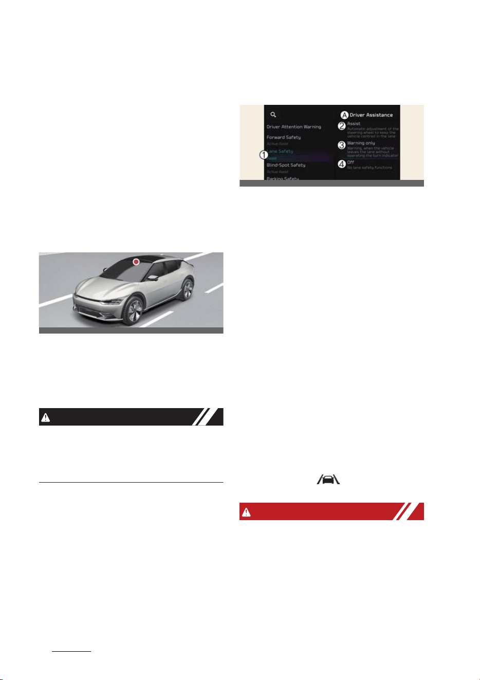
Driving your vehicle
626
Lane Keeping Assist (LKA)
Lane Keeping Assist (LKA) (if
equipped)
Lane Keeping Assist is designed to help
detect lane markings (or road edges)
while driving over a certain speed. Lane
Keeping Assist will warn the driver if the
vehicle leaves the lane without using the
turn signal, or will automatically assist
the driver's steering to help prevent the
vehicle from departing the lane.
Detecting sensor
Front view camera
The front view camera is used as a
detecting sensor to detect lane markings
(or road edges).
Refer to the picture above for the
detailed location of the detecting sensor.
CAUTION
For more details on the precautions of
the front view camera, refer to "Forward
Collision-Avoidance Assist (FCA) (if
equipped)" on page 6-43.
Lane Keeping Assist settings
Lane safety
A:
Driver assistance
1 Lane safety
2 Assist
3 Warning only
4 Off
With the vehicle on, select or deselect
Settings
→
Vehicle
→
Driver assis
-
tance
→
Lane safety
from the infotain
-
ment system screen to set whether or
not to use each function.
僅
Assist
: Lane Keeping Assist will auto
-
matically assist the driver's steering
when lane departure is detected to
help prevent the vehicle from moving
out of its lane.
僅
Warning only
: Lane Keeping Assist
will warn the driver with an audible
warning and steering wheel vibration
when lane departure is detected. The
driver must steer the vehicle.
僅
Off
: Lane Keeping Assist will turn off.
The indicator ( ) light will turn off
on the cluster.
WARNING
僅If
Warning only
is selected, steering is
not assisted.
僅 Lane Keeping Assist does not control
the steering wheel when the vehicle is
driven in the middle of the lane.
OCV051017L
OCV041565L
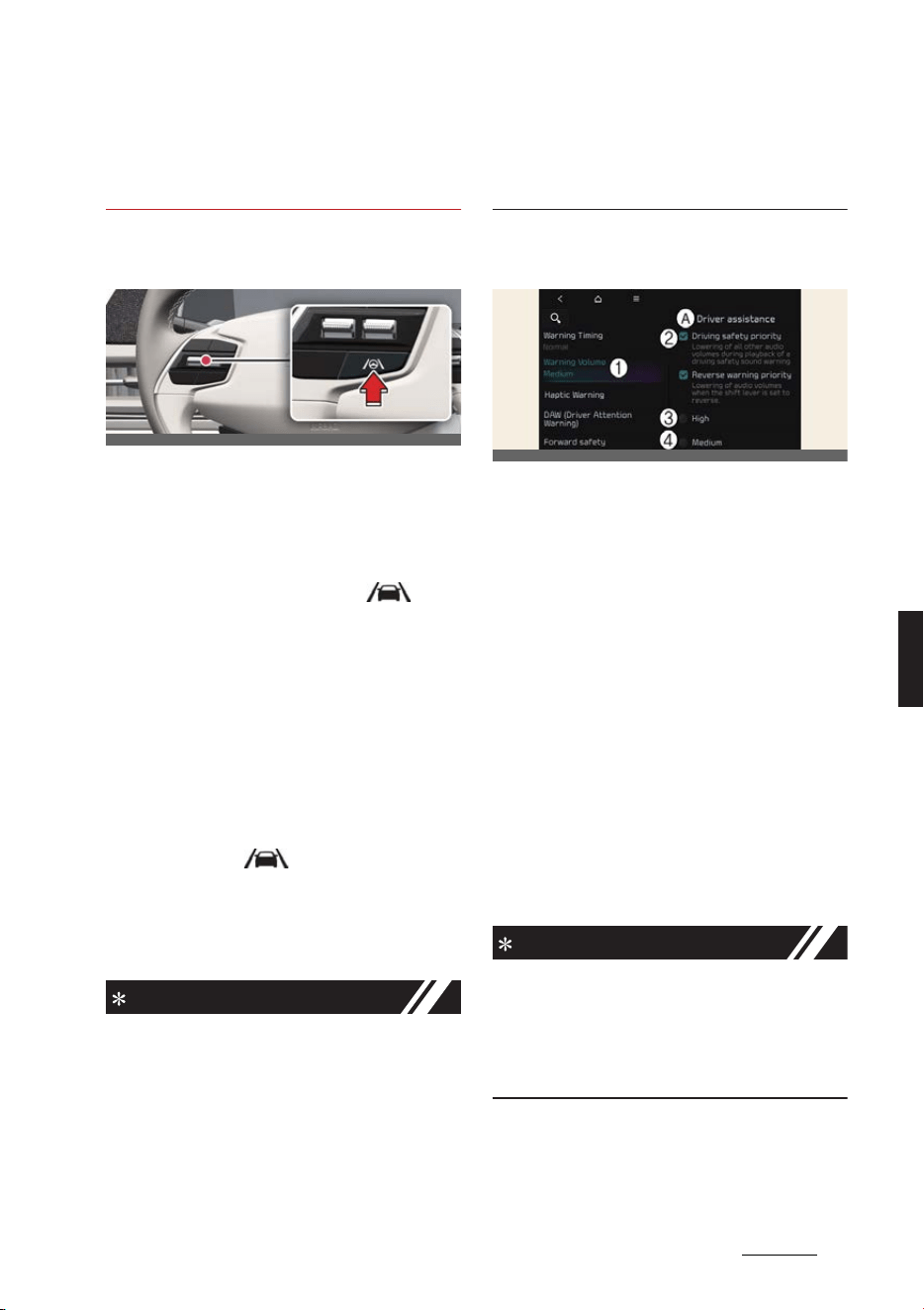
63
6
6
Driving your vehicle Lane Keeping Assist (LKA)
僅 The driver should always be aware of
the surroundings and steer the vehi
-
cle if
Off
is selected.
Turning Lane Keeping Assist On/
Off
Except Europe, Australia, Russia
With the vehicle on, press and hold the
Lane Driving Assist button located on
the steering wheel to turn on Lane Keep
-
ing Assist. The grey or green ( ) indi
-
cator light will illuminate on the cluster.
Press and hold the button again to turn
off the function.
If the vehicle is restarted, Lane Keeping
Assist will maintain the last setting.
For Europe, Australia, Russia
Whenever the vehicle is turned on, Lane
Keeping Assist will always turn on. The
white or green ( ) indicator light will
illuminate on the cluster.
When Lane Keeping Assist is on, press
and hold the Lane Driving Assist button
to turn off the function.
NOTICE
僅 When the Lane Driving Assist button
is pressed shortly, Lane Following
Assist will turn on and off.
僅 When Lane Keeping Assist is turned
off with the Lane Driving Assist but
-
ton, the Lane Safety setting also
changes to
Off
.
僅 Except Europe, Australia, Russia, if the
vehicle is restarted, Lane Keeping
Assist will maintain the last setting.
Warning volume
A:
Driver assistance
1 Warning volume
2 Driving safety priority
3 High
4 Medium
5 Low
6 Off
With the vehicle on, Settings
→
Vehi
-
cle
→
Driver assistance
→
Driving
safety
→
Warning volume
on the info
-
tainment system to change the Warning
volume to adjust the Warning volume
levels;
High
,
Medium
,
Low
or
Off
.
If
Driving safety priority
is selected, the
audio volume will temporarily decrease
to warn the driver with the audible warn
-
ing for safe driving.
NOTICE
僅 If you change the Warning volume,
the Warning volume of other Driver
Assistance systems may change.
僅If
Off
is selected, steering wheel
vibration will not turn off.
OCV051033L
OCVGT042562L
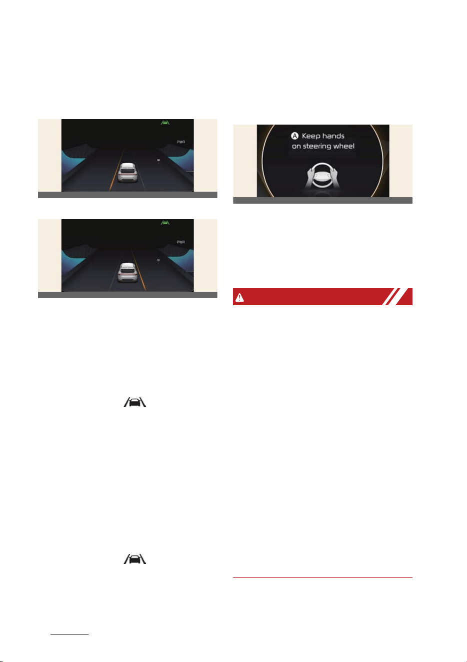
Driving your vehicle
646
Lane Keeping Assist (LKA)
Lane Keeping Assist operation
Warning and control
Left
Right
Lane Keeping Assist will warn and con
-
trol the vehicle with Lane Departure
Warning and Lane Keeping Assist.
Lane Departure Warning
僅 To warn the driver that the vehicle is
departing from the projected lane in
front, the green ( ) indicator light
will blink on the cluster, the lane line
will blink on the cluster depending on
which direction the vehicle is veering,
and an audible warning will sound.
Also, the steering wheel will vibrate.
僅 Vehicle speed: Approximately
60~200 km/h (40~120 mph).
Lane Keeping Assist
僅 To warn the driver that the vehicle is
departing from the projected lane in
front, the green ( ) indicator light
will blink on the cluster, and the steer
-
ing wheel will make adjustments to
keep vehicle inside the lane.
僅 Vehicle speed: Approximately
60~200 km/h (40~120 mph).
Hands-off warning
A:
Keep hands on steering wheel
If the driver takes their hands off the
steering wheel for several seconds, the
warning message will appear on the
cluster, and an audible warning will
sound in stages.
WARNING
僅 The steering wheel may not be
assisted if the steering wheel is held
very tight or the steering wheel is
steered over a certain degree.
僅 Lane Keeping Assist does not operate
at all times. It is the responsibility of
the driver to safely steer the vehicle
and to maintain the vehicle in its lane.
僅 The hands–off warning message may
appear late depending on road condi
-
tions. Always have your hands on the
steering wheel while driving.
僅 If the steering wheel is held very
lightly, the hands–off warning mes
-
sage may appear because Lane Keep
-
ing Assist may not detect that the
driver has their hands on the steering
wheel.
僅 If you attach objects to the steering
wheel, the hands-off warning may not
work properly.
OCV051131L
OCV051132L
OCV051133L
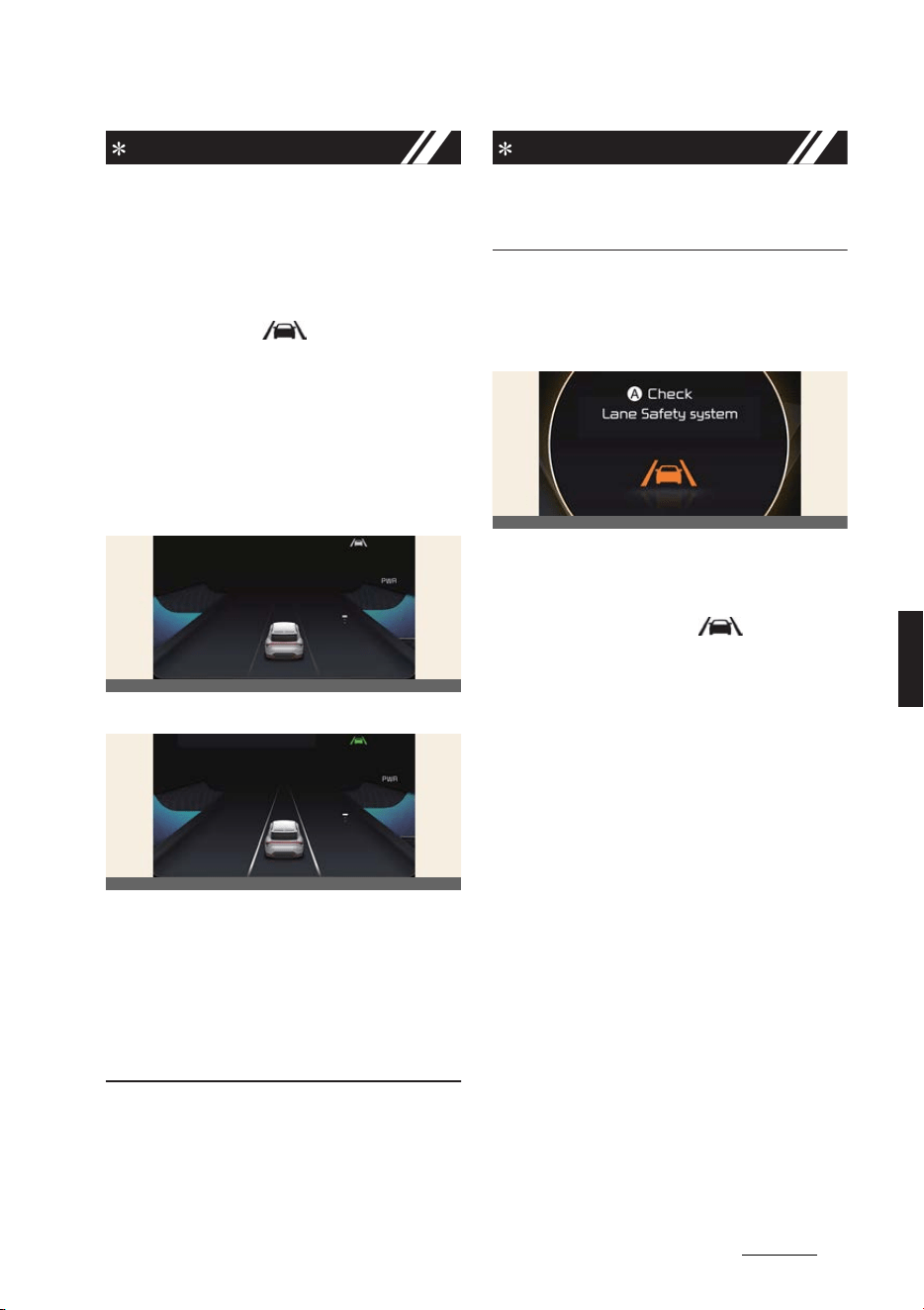
65
6
6
Driving your vehicle Lane Keeping Assist (LKA)
NOTICE
僅 For more details on setting the instru
-
ment cluster, refer to "Instrument
cluster" on page 5-45.
僅 When lane markings (or road edges)
are detected, the lane lines on the
cluster will change from gray to white
and the green ( ) indicator light
will illuminate.
僅 When the lane markings (or road
edges) are detected and Highway
Lane Change Assist is on, the lane
lines on the cluster may change to
green.
Lane undetected
Lane detected
僅 Even though the steering is assisted
by Lane Keeping Assist, the driver
may control the steering wheel.
僅 The steering wheel may feel heavier
or lighter when the steering wheel is
assisted by Lane Keeping Assist than
when it is not.
NOTICE
The images or colors may be displayed
differently depending on the specifica
-
tions of the instrument cluster or theme.
Lane Keeping Assist malfunction
and limitations
Lane Keeping Assist malfunction
A:
Check Lane Safety system
When Lane Keeping Assist is not work
-
ing properly, the warning message will
appear and the yellow ( ) indicator
light will illuminate on the cluster. If this
occurs, have the function inspected by a
professional workshop. Kia recommends
visiting an authorized Kia dealer/service
partner.
Limitations of Lane Keeping
Assist
Lane Keeping Assist may not operate
normally or may operate unexpectedly
under the following circumstances:
僅 The lane is contaminated or difficult
to distinguish because,
- The lane markings (or road edge) is
covered with rain, snow, dirt, sand,
oil, puddle etc.
- The color of the lane marking (or
road edge) is not distinguishable
from the road
- There are markings (or road edges)
on the road near the lane or the
markings (or road edges) on the
OCV051134L
OCV051135L
OCV051136L

Driving your vehicle
666
Lane Keeping Assist (LKA)
road looks similar to the lane mark
-
ings (or road edges)
- The lane marking (or road edge) is
indistinct or damaged
- The shadow is on the lane marking
(or road edge) by a median strip,
trees, guardrail, noise barriers, etc.
僅 The lane number increases or
decreases, or the lane markings are
crossing
僅 There are more than two lane mark
-
ings (or road edges) on the road
僅 The lane markings (or road edges) are
complicated or a structure substitutes
for the lines, such as a construction
area
僅 There are road markings, such as zig
-
zag lanes, crosswalk markings and
road signs
僅 The lane suddenly disappears, such
as at the intersection
僅 The lane (or road width) is very wide
or narrow
僅 There is a road edge without a lane
僅 There is a boundary structure in the
roadway, such as a tollgate, sidewalk,
curb, etc.
僅 The distance to the front vehicle is
extremely short or the vehicle in front
is covering the lane marking (or road
edge)
NOTICE
For more details on the limitations of the
front view camera, refer to "Forward Col
-
lision-Avoidance Assist (FCA) (if
equipped)" on page 6-43.
WARNING
Take the following precautions when
using Lane Keeping Assist:
僅 The driver should hold the responsi
-
bility to safely drive and control the
vehicle. Do not solely rely on the func
-
tion and drive dangerously.
僅 The operation of Lane Keeping Assist
can be canceled or not work properly
depending on road conditions and
surroundings. Always be cautious
while driving.
僅 Refer to "Limitations of Lane Keeping
Assist" if the lane is not detected prop
-
erly.
僅 When you are towing a trailer or
another vehicle, we recommend that
Lane Keeping Assist is turned off due
to safety reasons.
僅 If the vehicle is driven at high speed,
the steering wheel will not be con
-
trolled. The driver must always follow
the speed limit when using Lane
Keeping Assist.
僅 If any other function's warning mes
-
sage is displayed or audible warning
is generated, Lane Keeping Assist
warning message may not be dis
-
played and audible warning may not
be generated.
僅 You may not hear the warning sound
of Lane Keeping Assist if the sur
-
rounding is noisy.
僅 If you attach objects to the steering
wheel, steering may not be assisted
properly.
僅 Lane Keeping Assist may not operate
for 15 seconds after the vehicle is
started, or the Front view camera is
initialized.
僅 Lane Keeping Assist will not operate
when:
- The turn signal or hazard waring
flasher is turned on
- The vehicle is not driven in the cen
-
ter of the lane when the function is
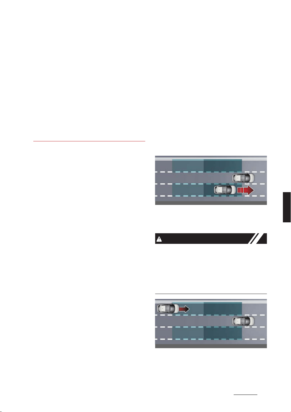
67
6
6
Driving your vehicle Blind-Spot Collision-Avoidance Assist (BCA)
turned on or right after changing a
lane
- ESC (Electronic Stability Control) or
VSM (Vehicle Stability Manage
-
ment) is activated
- The vehicle is driven on a sharp
curved road
- Vehicle speed is below 55 km/h (35
mph) or above 210 km/h (130 mph)
- The vehicle makes sharp lane
changes
- The vehicle brakes suddenly
Blind-Spot Collision-Avoid
-
ance Assist (BCA) (if
equipped)
Blind-Spot Collision-Avoidance Assist is
designed to help detect and monitor
approaching vehicles in the driver's blind
spot area and warn the driver of a possi
-
ble collision with a warning message and
audible warning.
In addition, if there is a risk of collision
when changing lanes or driving forward
out of a parking space, Blind-Spot Colli
-
sion-Avoidance Assist will help avoid col
-
lision by applying the brake.
Blind-Spot Collision-Avoidance Assist
helps detect and inform the driver that a
vehicle is in the blind spot.
CAUTION
The detecting range may vary depend
-
ing on the speed of your vehicle. How
-
ever, even if there is a vehicle in the
blind spot area, the function may not
warn you when you pass by at high
speeds.
Blind-Spot Collision-Avoidance Assist
helps detect and inform the driver that a
vehicle is approaching at high speed
from the blind spot area.
OCV051034L
OCV051035L
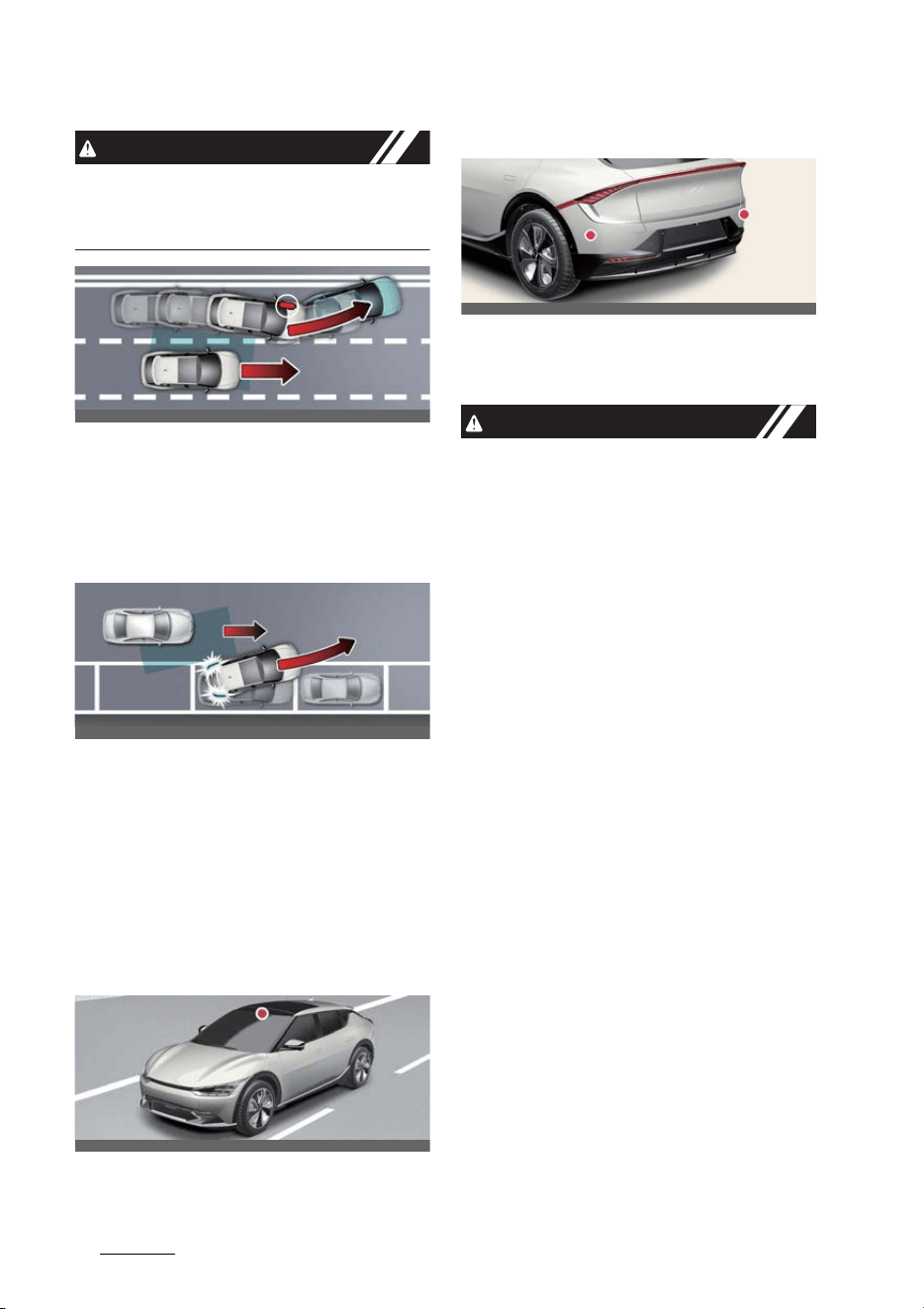
Driving your vehicle
686
Blind-Spot Collision-Avoidance Assist (BCA)
CAUTION
Warning timing may vary depending on
the speed of the vehicle approaching at
high speed.
When changing lanes by detecting the
lane ahead, if Blind-Spot Collision-Avoid
-
ance Assist judges that there is a colli
-
sion risk with an approaching vehicle in
the blind spot, it will help avoid collision
by applying the brake.
When you are driving forward out of a
parking space, if Blind-Spot Collision-
Avoidance Assist judges that there is a
collision risk with an approaching vehicle
in the blind spot, it will help avoid colli
-
sion by applying the brake.
Detecting sensor
Front view camera
Rear corner radar
Refer to the picture above for the
detailed location of the detecting sen
-
sors.
CAUTION
Take the following precautions to main
-
tain optimal performance of the detect
-
ing sensor:
僅 Never disassemble the rear corner
radar or radar assembly, or apply any
impact on it.
僅 If there is impact on the rear corner
radar or near the radar, even though
the warning message does not appear
on the cluster, Blind-Spot Safety sys
-
tem may not operate properly. Have
the function be inspected by a profes
-
sional workshop. Kia recommends vis
-
iting an authorized Kia dealer/service
partner.
僅 If the rear corner radars have been
replaced or repaired, have the vehicle
inspected by a professional workshop.
Kia recommends visiting an autho
-
rized Kia dealer/service partner.
僅 The genuine Kia rear bumpers which
the rear corner radar sensors are
mounted are parts with quality and
performance ensured. If arbitrarily
applying paint on or changing the
bumper, the Blind-Spot Collision-
Avoidance Assist may not function
properly.
Use only Kia Genuine Parts or those
of an equivalent standard with proven
OCV051036L
OCV051037L
OCV051017L
OCV051025L
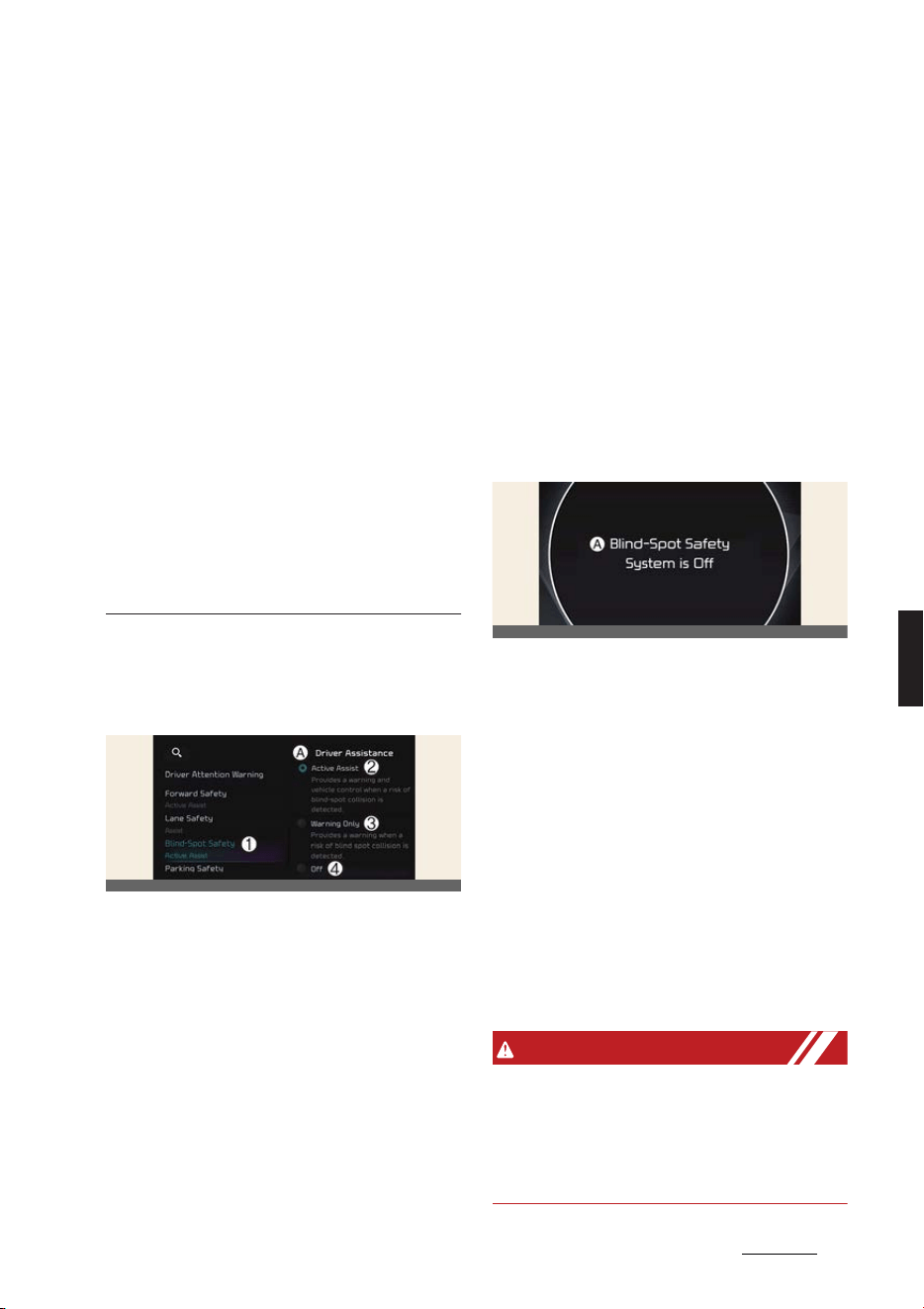
69
6
6
Driving your vehicle Blind-Spot Collision-Avoidance Assist (BCA)
quality and performance to repair or
replace the bumper.
僅 Do not apply license plate frame or
objects, such as a bumper sticker, film
or a bumper guard near the rear cor
-
ner radar.
僅 Blind-Spot Collision-Avoidance Assist
may not work properly if the bumper
has been replaced, or the surround
-
ings of the rear corner radar has been
damaged or paint has been applied.
僅 If a trailer, carrier or other equipments
is installed, it may adversely affect the
performance of the rear corner radar
or the function may not operate.
For more details on the precautions of
the front view camera, refer to "Forward
Collision-Avoidance Assist (FCA) (if
equipped)" on page 6-43.
Blind-Spot Collision-Avoidance
Assist settings
Blind-spot safety
A:
Driver assistance
1 Blind-spot safety
2 Active assistance
3 Warning only
4 Off
With the vehicle on, select or deselect
Settings
→
Vehicle
→
Driver assis
-
tance
→
Blind-spot safety
from the
infotainment system screen to set
whether or not to use each function.
僅
Active assistance
: Blind-Spot Colli
-
sion-Avoidance Assist will warn the
driver with a warning message, an
audible warning, steering wheel vibra
-
tion and braking assist will be applied
depending on the collision risk levels.
僅
Warning only
: Blind-Spot Collision-
Avoidance Assist will warn the driver
with a warning message, an audible
warning and steering wheel vibration
depending on the collision risk levels.
Braking will not be assisted.
僅
Off
: Blind-Spot Collision-Avoidance
Assist will turn off.
A:
Blind-Spot Safety System is Off
When the vehicle is restarted with Blind-
Spot Collision-Avoidance Assist off, the
Blind-Spot Safety System is Off
mes
-
sage will appear on the cluster.
If you change the setting from
Off
to
Active Assist
or
Warning only
, the
warning light on the outside rear view
mirror will blink for three seconds.
In addition, if the vehicle is turned on,
when Blind-Spot Collision-Avoidance
Assist is set to
Active Assist
or
Warning
only
, the warning light on the outside
rear view mirror will blink for three sec
-
onds.
WARNING
僅If
Warning only
is selected, braking is
not assisted.
僅If
Off
is selected, the driver should
always be aware of the surroundings
and drive safely.
OCV041566L
OCV051137L
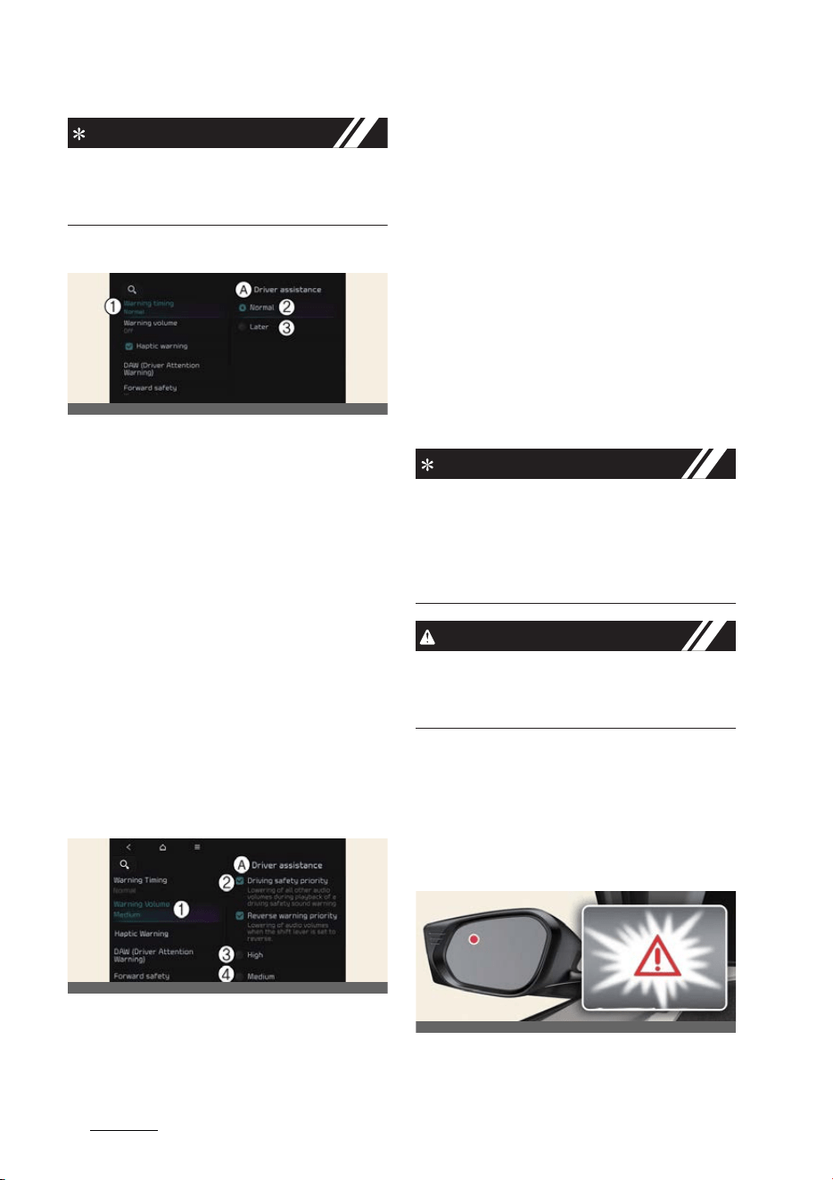
Driving your vehicle
706
Blind-Spot Collision-Avoidance Assist (BCA)
NOTICE
If the vehicle is restarted, Blind-Spot Col
-
lision-Avoidance Assist will maintain the
last setting.
Warning timing
A:
Driver assistance
1 Warning timing
2 Normal
3 Late
With the vehicle on, select
Settings
→
Vehicle
→
Driver assistance
→
Warn
-
ing timing
from the infotainment sys
-
tem screen to change the initial warning
activation time for Blind-Spot Collision-
Avoidance Assist.
To select the Warning time
Normal
or
Late
.
僅
Normal
: Use under normal driving
conditions. If it feels too sensitive, set
the warning timing to
Late
.
僅
Late
: The warning timing will be late
Warning volume
A:
Driver assistance
1 Warning volume
2 Driving safety priority
3 High
4 Medium
5 Low
6 Off
With the vehicle on,
Settings
→
Vehicle
→
Driver assistance
→
Driving safety
→
Warning volume
on the infotainment
system to change the Warning volume
to adjust the Warning volume levels;
High
,
Medium
,
Low
or
Off
.
If
Driving safety priority
is selected, the
audio volume will temporarily decrease
to warn the driver with the audible warn
-
ing for safe driving.
NOTICE
僅 If you change the Warning volume,
the Warning volume of other Driver
Assistance systems may change.
僅If
Off
is selected, steering wheel
vibration will not turn off.
CAUTION
The setting of the Warning volume
applies to all functions of Blind-Spot Col
-
lision-Avoidance Assist.
Blind-Spot Collision-Avoidance
Assist operation
Warning and control
Vehicle detection
OCVGT042587L
OCVGT042562L
OCV051038L
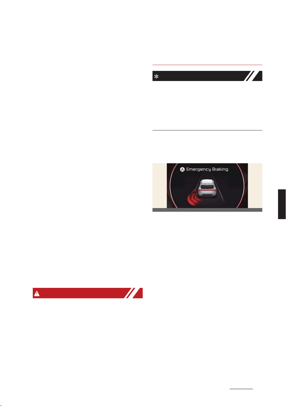
71
6
6
Driving your vehicle Blind-Spot Collision-Avoidance Assist (BCA)
僅 Warning light will appear in the out
-
side rear view mirror and head-up dis
-
play (if equipped).
Blind-Spot Collision-Avoidance Assist
will operate as following circumstances.
僅 Vehicle speed: Above 20 km/h (12
mph)
僅 The speed of the vehicle in the blind
spot area: Above 10 km/h (7 mph)
Collision warning
Collision warning will operate when the
turn signal to change the lane in the
direction of the vehicle in the blind spot
area.
僅If
Warning only
is selected from the
Settings menu, the collision warning
will operate when your vehicle
approaches the lane the blind spot
vehicle is detected.
僅 To warn the driver of a collision, the
warning light on the side view mirror
and head-up display (if equipped) will
blink. At the same time, an audible
warning will sound and the steering
wheel will vibrate.
僅 When the turn signal is turned off or
you move away from the lane, the col
-
lision warning will be canceled and
the function will return to vehicle
detection state.
WARNING
僅 The detecting range of the rear corner
radar is determined by a standard
road width, therefore, on a narrow
road, the function may detect other
vehicles in the two lanes away and
warn you. In contrast, on a wide road,
the function may not be able to detect
a vehicle driving in the next lane and
may not warn you.
僅 When the hazard warning flasher is
on, the collision warning by the turn
signal will not operate.
NOTICE
If the driver's seat is on the left side, the
collision warning may occur when you
turn left. If the driver's seat is on the right
side, the collision warning may occur
when you turn right. Maintain a proper
distance with the vehicles in the lane.
Collision-Avoidance Assist (while
driving)
A:
Emergency braking
僅 To warn the driver of a collision, the
warning light on the side view mirror
will blink and a warning message will
appear on the cluster. At the same
time, an audible warning will sound,
warning light on the head-up display
(if equipped) will blink and the steer
-
ing wheel will vibrate. It assists in
braking control to help prevent colli
-
sion with the vehicle in the blind spot
area.
僅 Collision-Avoidance Assist will be
operated under the following circum
-
stances.
- Your vehicle speed: 60~200 km/h
(40~120 mph)
- Both lane markings of the driving
lane are detected.
OCVGT052283L
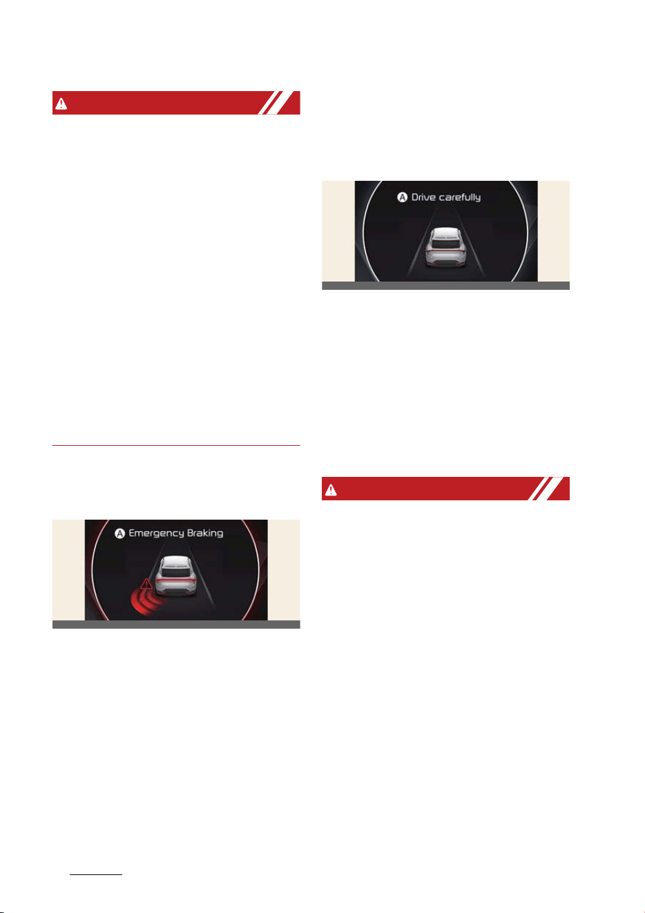
Driving your vehicle
726
Blind-Spot Collision-Avoidance Assist (BCA)
WARNING
僅 Collision-Avoidance Assist will be can
-
celed under the following circum
-
stances:
- Your vehicle enters the next lane by
a certain distance
- Your vehicle is away from the colli
-
sion risk
- The steering wheel is sharply
steered
- The brake pedal is depressed
- Forward Collision-Avoidance Assist
is operating
僅 After Blind-Spot Collision-Avoidance
Assist operation or changing lane, you
must drive to the center of the lane.
The function will not operate if the
vehicle is not driven in the center of
the lane.
Collision-Avoidance Assist (while
departing)
A:
Emergency braking
僅 To warn the driver of a collision, the
warning light on the outside rear view
mirror will blink and a warning mes
-
sage will appear on the cluster. At the
same time, an audible warning will
sound, warning light on the head-up
display (if equipped) will blink and the
steering wheel will vibrate.
僅 Blind-Spot Collision-Avoidance Assist
will operate when your vehicle speed
is below 3 km/h (2 mph) and the
speed of the vehicle in the blind spot
area is above 5 km/h (3 mph).
僅 Emergency braking will be assisted to
help prevent collision with the vehicle
in the blind spot area.
A:
Drive carefully
When the vehicle is stopped due to
emergency braking, the warning mes
-
sage will appear on the cluster. For your
safety, the driver should depress the
brake pedal immediately and check the
surroundings.
僅 Brake control will end after the vehicle
is stopped by emergency braking for
approximately 2 seconds.
WARNING
Take the following precautions when
using Blind-Spot Collision-Avoidance
Assist:
僅 For your safety, change the Blind-
Spot Safety system Settings after
parking the vehicle at a safe location.
僅 If any other function's warning mes
-
sage is displayed or audible warning
is generated, Blind-Spot Collision-
Avoidance Assist's warning message
may not be displayed and audible
warning may not be generated.
僅 You may not hear the warning sound
of Blind-Spot Collision-Avoidance
Assist if the surrounding is noisy.
僅 Blind-Spot Collision-Avoidance Assist
may not operate if the driver applies
the brake pedal to avoid collision.
OCVGT052283L
OCV051118L
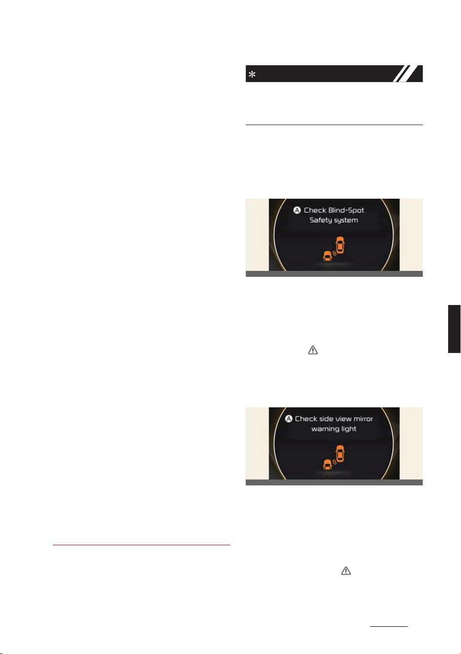
73
6
6
Driving your vehicle Blind-Spot Collision-Avoidance Assist (BCA)
僅 When Blind-Spot Collision-Avoidance
Assist is operating, braking control by
the function will automatically cancel
when the driver excessively depresses
the accelerator pedal or control the
steering wheel.
僅 During Blind-Spot Collision-Avoidance
Assist operation, the vehicle may stop
suddenly injuring passengers and
shifting loose objects. Always have the
seat belt on and keep loose objects
secured.
僅 Even if there is a problem with Blind-
Spot Collision-Avoidance Assist, the
vehicle's basic braking performance
will operate normally.
僅 Blind-Spot Collision-Avoidance Assist
does not operate in all situations or
cannot avoid all collisions.
僅 Blind-Spot Collision-Avoidance Assist
may warn the driver late or may not
warn the driver depending on the
road and driving conditions.
僅 Driver should maintain control of the
vehicle at all times. Do not depend on
Blind-Spot Collision-Avoidance Assist.
Maintain a safe braking distance, and
if necessary, depress the brake pedal
to reduce driving speed or to stop the
vehicle.
僅 The brake control may not operate
properly depending on the status of
ESC (Electronic Stability Control).
There will only be a warning when:
- The ESC (Electronic Stability Con
-
trol) warning light is on
- ESC (Electronic Stability Control) is
engaged in a different function
NOTICE
The images or colors may be displayed
differently depending on the specifica
-
tions of the instrument cluster or theme.
Blind-Spot Collision-Avoidance
Assist malfunction and limitations
Blind-Spot Collision-Avoidance
Assist malfunction
A:
Check Blind-Spot Safety system
When Blind-Spot Collision-Avoidance
Assist is not working properly, the warn
-
ing message will appear on the cluster
for several seconds, and the master
warning light ( ) will illuminate. Have
Blind-Spot Collision-Avoidance Assist be
inspected by a professional workshop.
Kia recommends visiting an authorized
Kia dealer/service partner.
A:
Check side view mirror warning
light
When the outside rear view mirror warn
-
ing light is not working properly, the
warning message will appear on the
cluster for several seconds, and the
master warning light ( ) will illuminate.
Have Blind-Spot Collision-Avoidance
Assist be inspected by a professional
OCV051139L
OCV051140L
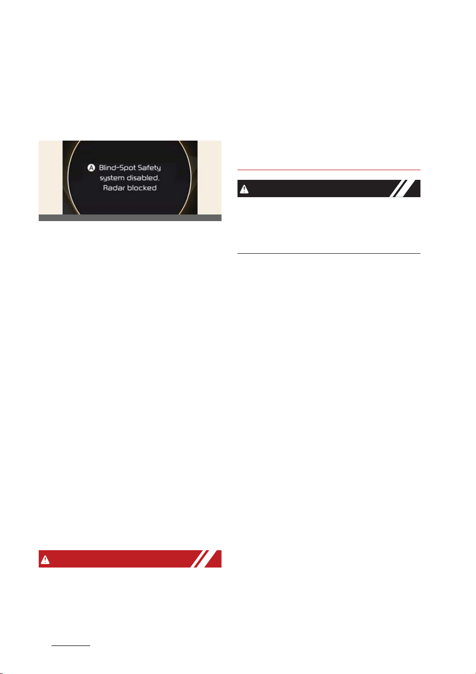
Driving your vehicle
746
Blind-Spot Collision-Avoidance Assist (BCA)
workshop. Kia recommends visiting an
authorized Kia dealer/service partner.
Blind-Spot Collision-Avoidance
Assist disabled
A:
Blind-spot safety system disabled.
Radar blocked
When the rear bumper around the rear
corner radar or sensor is covered with
foreign material, such as snow or rain, or
installing a trailer or carrier, it can reduce
the detecting performance and tempo
-
rarily limit or disable Blind-Spot Colli
-
sion-Avoidance Assist.
If this occurs, a warning message will
appear on the cluster. However it is not a
malfunction.
Blind-Spot Collision-Avoidance Assist
will operate normally when such foreign
material or trailer, other equipments is
removed, and then the vehicle is
restarted. Always keep it clean.
If Blind-Spot Collision-Avoidance Assist
does not operate normally vehicle rear
luggage, other equipment or foreign
material is removed, have Blind-Spot
Collision-Avoidance Assist be inspected
by a professional workshop. Kia recom
-
mends visiting an authorized Kia dealer/
service partner.
WARNING
僅 Even though the warning message
does not appear on the cluster, Blind-
Spot Collision-Avoidance Assist may
not properly operate.
僅 Blind-Spot Collision-Avoidance Assist
may not properly operate in an area
(e.g. open terrain) where any sub
-
stance are not detected right after the
vehicle is turned on, or when the
detecting sensor is blocked with for
-
eign material right after the vehicle is
turned on.
CAUTION
Turn off Blind-Spot Collision-Avoidance
Assist to install a trailer, carrier, etc., or
remove the trailer, carrier, etc. to use
Blind-Spot Collision-Avoidance Assist.
Limitations of Blind-Spot Colli
-
sion-Avoidance Assist
Blind-Spot Collision-Avoidance Assist
may not operate normally as following
circumstances:
僅 There is inclement weather, such as
heavy snow, heavy rain, etc.
僅 The rear corner radar is covered with
snow, rain, dirt, etc.
僅 The temperature around the rear cor
-
ner radar is high or low
僅 The rear corner radar is covered by
vehicle or pillar, walls etc.
僅 Driving on a highway (or motorway)
ramp and tollgate.
僅 The road pavement (or the peripheral
ground) abnormally contains metallic
components (i.e. possibly due to sub
-
way construction).
僅 There is a fixed object near the vehi
-
cle, such as sound barriers, guardrails,
double guardrails, central dividers,
entry barriers, street lamps, signs,
tunnels, walls, etc. (including double
structures)
僅 Driving through a narrow road where
trees or grass are overgrown
OCV051141L
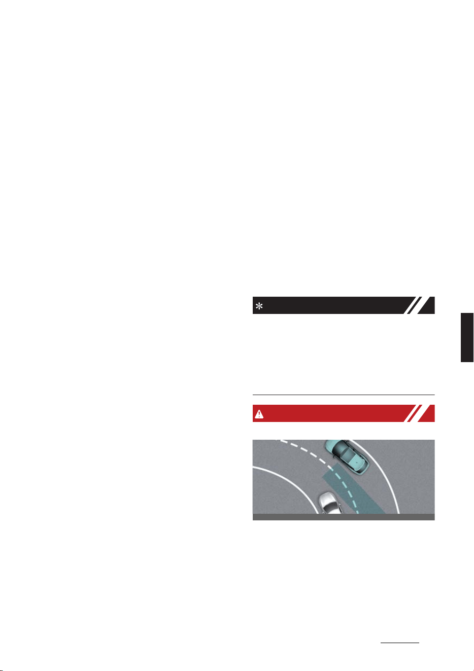
75
6
6
Driving your vehicle Blind-Spot Collision-Avoidance Assist (BCA)
僅 Driving in large areas where there are
few vehicles or structures (i.e. desert,
meadow, suburb, etc.)
僅 Driving on a wet road surface, such as
a puddle on the road
僅 The other vehicle drives very close
behind your vehicle, or the other vehi
-
cle passes by your vehicle in close
proximity
僅 The speed of the other vehicle is very
fast that it passes by your vehicle in a
short time
僅 Your vehicle passes by the other vehi
-
cle
僅Your vehicle changes lane
僅 Your vehicle has started at the same
time as the vehicle next to you and
has accelerated
僅 The vehicle in the next lane moves
two lanes away from you, or when the
vehicle two lanes away moves to the
next lane from you
僅 A trailer or carrier is installed around
the rear corner radar
僅 The bumper around the rear corner
radar is covered with objects, such as
a bumper sticker, bike rack, etc.
僅 The bumper around the rear corner
radar is impacted, damaged or the
radar is out of position
僅 Your vehicle height is low or high due
to heavy loads, abnormal tire pres
-
sure, etc.
Blind-Spot Collision-Avoidance Assist
may not operate normally, or it may
operate unexpectedly when the follow
-
ing objects are detected:
僅 A motorcycle or bicycle is detected
僅 A vehicle such as a flat trailer is
detected
僅 A big vehicle such as a bus or truck is
detected
僅 A moving obstacle such as a pedes
-
trian, animal, shopping cart or a baby
stroller is detected
僅 A vehicle with low height such as a
sports car is detected
Braking control may not work as follow
-
ing circumstances:
僅 The vehicle severely vibrates while
driving over a bumpy road, uneven
road or concrete patch
僅 Driving on a slippery surface due to
snow, water puddle, ice, etc.
僅 The tire pressure is low or a tire is
damaged
僅 The brake is reworked
僅 The vehicle makes abrupt lane
changes
NOTICE
For more details on the limitations of the
front view camera, refer to "Forward Col
-
lision-Avoidance Assist (FCA) (if
equipped)" on page 6-43 and "Lane
Keeping Assist (LKA) (if equipped)" on
page 6-62.
WARNING
僅 Driving on a curved road
Blind-Spot Collision-Avoidance Assist
may not operate properly when driv
-
ing on a curved road. Blind-Spot Colli
-
sion-Avoidance Assist may not detect
the vehicle in the next lane.
Always pay attention to road and driv
-
ing conditions while driving.
OCV051039L
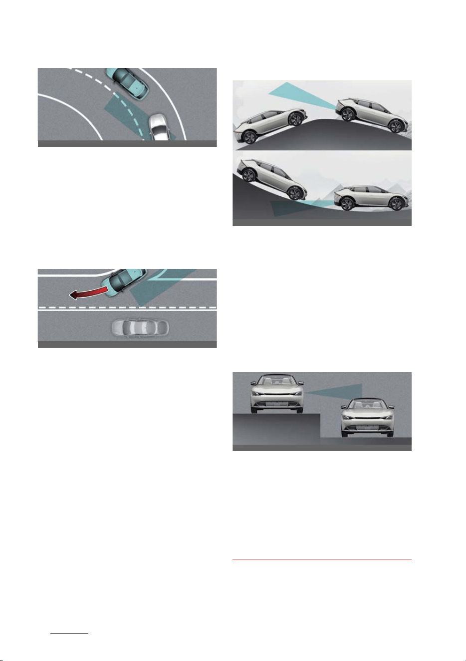
Driving your vehicle
766
Blind-Spot Collision-Avoidance Assist (BCA)
Blind-Spot Collision-Avoidance Assist
may not operate properly when driv
-
ing on a curved road. Blind-Spot Colli
-
sion-Avoidance Assist may detect a
vehicle in the same lane.
Always pay attention to road and driv
-
ing conditions while driving.
僅 Driving where the road is merging/
dividing
Blind-Spot Collision-Avoidance Assist
may not operate properly when driv
-
ing where the road merges or divides.
Blind-Spot Collision-Avoidance Assist
may not detect the vehicle in the next
lane.
Always pay attention to road and driv
-
ing conditions while driving on the
road merges or divides.
僅 Driving on an inclined road
Blind-Spot Collision-Avoidance Assist
may not operate properly when driv
-
ing on a sloped road. Blind-Spot Colli
-
sion-Avoidance Assist may not detect
the vehicle in the next lane or may
incorrectly detect the ground or struc
-
ture.
Always pay attention to road and driv
-
ing conditions while driving.
僅 Driving where the heights of the lanes
are different
Blind-Spot Collision-Avoidance Assist
may not operate properly when driv
-
ing where the heights of the lanes are
different. Blind-Spot Collision-Avoid
-
ance Assist may not detect the vehicle
on a road with different lane heights.
Always pay attention to road and driv
-
ing conditions while driving.
OCV051040L
OCV051041L
OCV051042L_2
OCV051043L
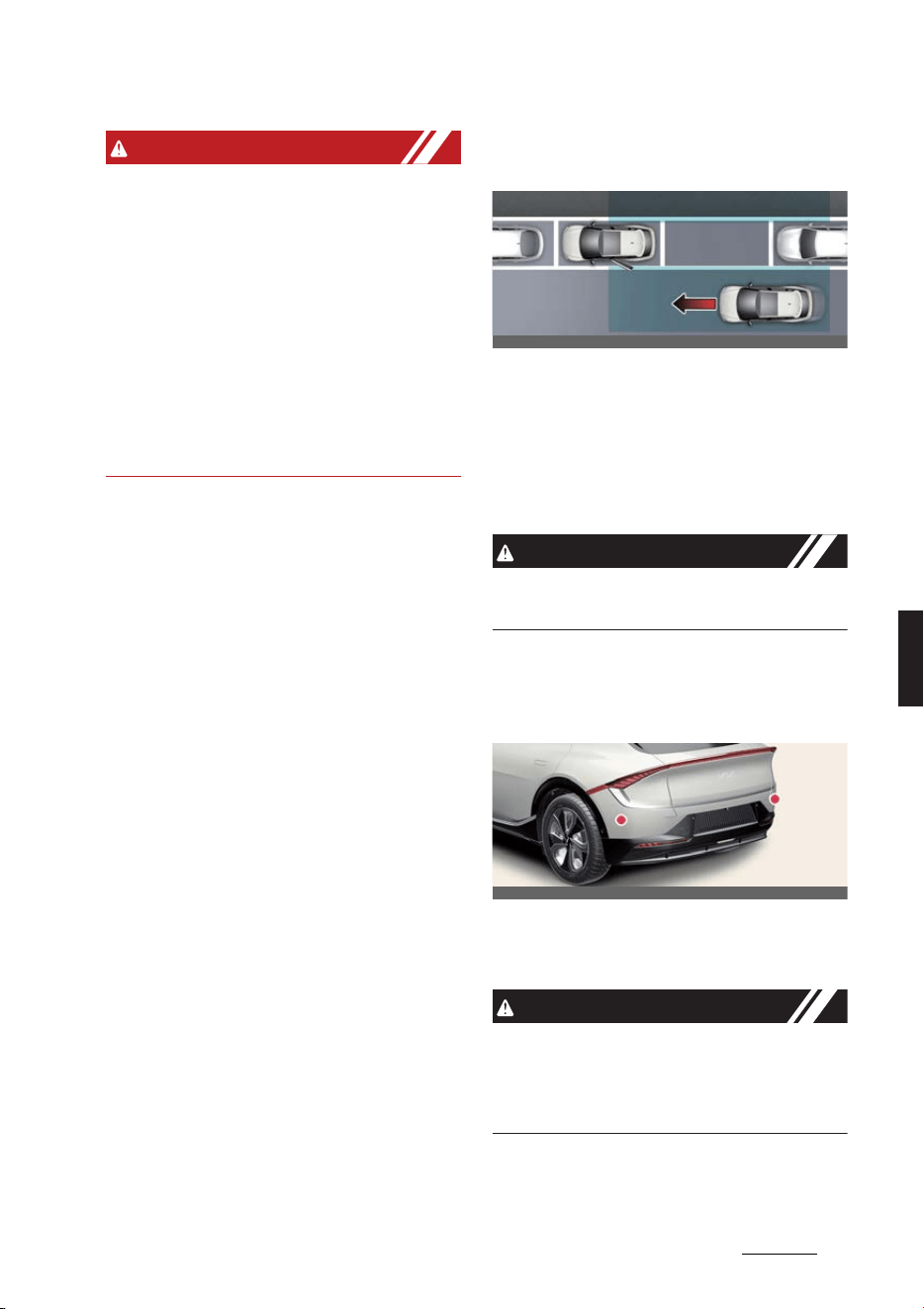
77
6
6
Driving your vehicle Safe Exit Warning (SEW)
WARNING
僅 When you are towing a trailer or
another vehicle, make sure that you
turn off Blind-Spot Collision-Avoid
-
ance Assist.
僅 Blind-Spot Collision-Avoidance Assist
may not operate normally if interfered
by strong electromagnetic waves.
僅 Blind-Spot Collision-Avoidance Assist
may not operate for approximately 15
seconds after the vehicle is started, or
the front view camera or rear corner
radars are initialized.
Safe Exit Warning (SEW) (if
equipped)
After the vehicle stops, when an
approaching vehicle from the rear area
is detected as soon as a passenger
opens a door, Safe Exit Warning will
warn the driver with a warning message
and an audible warning to help prevent
a collision.
CAUTION
Warning timing may vary depending on
the speed of the approaching vehicle.
Detecting sensor
Rear corner radar
Refer to the picture above for the
detailed location of the detecting sen
-
sors.
CAUTION
For more details on the precautions of
the rear corner radars, refer to "Blind-
Spot Collision-Avoidance Assist (BCA) (if
equipped)" on page 6-67.
OCV051044L
OCV051025L
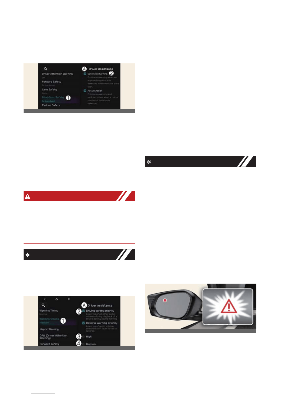
Driving your vehicle
786
Safe Exit Warning (SEW)
Safe Exit Warning (SEW) settings
SEW (Safe Exit Warning)
A:
Driver assistance
1 Blind-spot safety
2 SEW (Safe Exit Warning)
With the vehicle on, select
Settings
→
Vehicle
→
Driver assistance
→
Blind-
spot safety
→
SEW (Safe Exit Warning)
from the infotainment system screen to
turn on Safe Exit Warning and deselect
to turn off the function.
WARNING
The driver should always be aware of
unexpected and sudden situations from
occurring. If
SEW (Safe Exit Warning)
is
deselected, Safe Exit Warning cannot
assist you.
NOTICE
If the vehicle is restarted, Safe Exit Warn
-
ing will maintain the last setting.
Warning volume
A:
Driver assistance
1 Warning volume
2 Driving safety priority
3 High
4 Medium
5 Low
6 Off
With the vehicle on, Settings
→
Vehi
-
cle
→
Driver assistance
→
Driving
safety
→
Warning volume
on the info
-
tainment system to change the Warning
volume to adjust the Warning volume
levels;
High
,
Medium
,
Low
or
Off
.
If
Driving safety priority
is selected, the
audio volume will temporarily decrease
to warn the driver with the audible warn
-
ing for safe driving.
NOTICE
僅 If you change the Warning volume,
the Warning volume of other Driver
Assistance systems may change.
僅If
Off
is selected, steering wheel
vibration will not turn off.
Safe Exit Warning operation
Warning
Safe Exit Warning warns the following
actions.
Collision warning when exiting
vehicle
OCV041567L
OCVGT042562L
OCV051038L
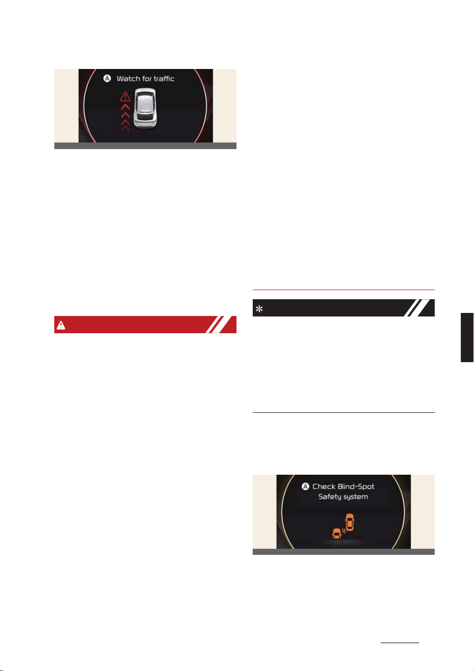
79
6
6
Driving your vehicle Safe Exit Warning (SEW)
A:
Watch for traffic
僅 The warning light on the side view
mirror will blink and the warning mes
-
sage will appear on the cluster, and an
audible warning will sound.
僅 Safe Exit Warning will warn under the
following circumstances:
- Your vehicle speed: below 3 km/h
(2 mph)
- The speed of the approaching vehi
-
cle from the rear: above 6 km/h (4
mph)
WARNING
Take the following precautions when
using Safe Exit Warning:
僅 For your safety, change the Settings
after parking the vehicle at a safe
location.
僅 If any other function's warning mes
-
sage is displayed or audible warning
is generated, Safe Exit Warning warn
-
ing message may not be displayed
and audible warning may not be gen
-
erated.
僅 You may not hear the warning sound
of Safe Exit Warning if the surround
-
ing is noisy.
僅 Safe Exit Warning does not operate in
all situations or cannot prevent all col
-
lisions.
僅 Safe Exit Warning may warn the
driver late or may not warn the driver
depending and driving conditions.
Always check vehicle surroundings.
僅 The driver and passengers are
responsible for accidents that occurs
while exiting the vehicle. Always check
the surroundings before you exit the
vehicle.
僅 Safe Exit Warning does not operate if
there is a problem with Blind-Spot
Collision-Avoidance Assist.
僅 The warning message of Blind-Spot
Collision-Avoidance Assist will appear
when:
- Blind-Spot Collision-Avoidance
Assist sensor or the sensor sur
-
rounding is polluted or covered
- Blind-Spot Collision-Avoidance
Assist fails to warn passengers or
falsely warn passengers
NOTICE
僅 After the vehicle is turned off, Safe
Exit Warning operates for 3 minutes,
but turns off immediately if the doors
are locked.
僅 Images or colors may be displayed
differently depends on the instrument
cluster specifications or theme.
Safe Exit Warning malfunction
and limitations
Safe Exit Warning malfunction
A:
Check Blind-Spot Safety system
When Safe Exit Warning is not working
properly, the warning message will
appear on the cluster, and the master
OCV051142L
OCV051139L
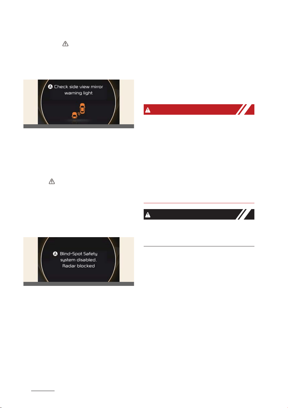
Driving your vehicle
806
Safe Exit Warning (SEW)
warning light ( ) will illuminate on the
cluster. Have Safe Exit Warning be
inspected by a professional workshop.
Kia recommends visiting an authorized
Kia dealer/service partner.
A:
Check side view mirror warning
light
When the side view mirror warning light
is not working properly, the warning
message will appear on the cluster for
several seconds, and the master warn
-
ing light ( ) will illuminate on the clus
-
ter. Have Safe Exit Warning be inspected
by a professional workshop. Kia recom
-
mends visiting an authorized Kia dealer/
service partner.
Safe Exit Warning disabled
A:
Blind-spot safety system disabled.
Radar blocked
When the rear bumper around the rear
corner radar or sensor is covered with
foreign material, such as snow or rain, or
installing a trailer or carrier, it can reduce
the detecting performance and tempo
-
rarily limit or disable Safe Exit Warning.
If this occurs, the
Blind-Spot Safety
system disabled. Radar blocked
warn
-
ing message will appear on the cluster.
Safe Exit Warning will operate normally
when such foreign material or trailer, etc.
is removed, and then the vehicle is
restarted.
If Safe Exit Warning does not operate
normally after it is removed, Kia recom
-
mends visiting an authorized Kia dealer/
service partner.
WARNING
僅 Even though the warning message
does not appear on the cluster, Safe
Exit Warning may not properly oper
-
ate.
僅 Safe Exit Warning may not properly
operate in an area (e.g., open terrain),
where any substance are not detected
right after the vehicle is turned on, or
when the detecting sensor is blocked
with foreign material right after the
vehicle is turned on.
CAUTION
Turn off Safe Exit Warning to install a
trailer, carrier, etc., or remove the trailer,
carrier, etc. to use Safe Exit Warning.
Limitations of Safe Exit Warning
Safe Exit Warning may not operate nor
-
mally, or Safe Exit Warning may operate
unexpectedly under the following warn
-
ing.
僅 Getting out of the vehicle where trees
or grass are overgrown
僅 Getting out of the vehicle where the
road is wet
僅 The approaching vehicle is very fast
or very slow
OCV051140L
OCV051141L
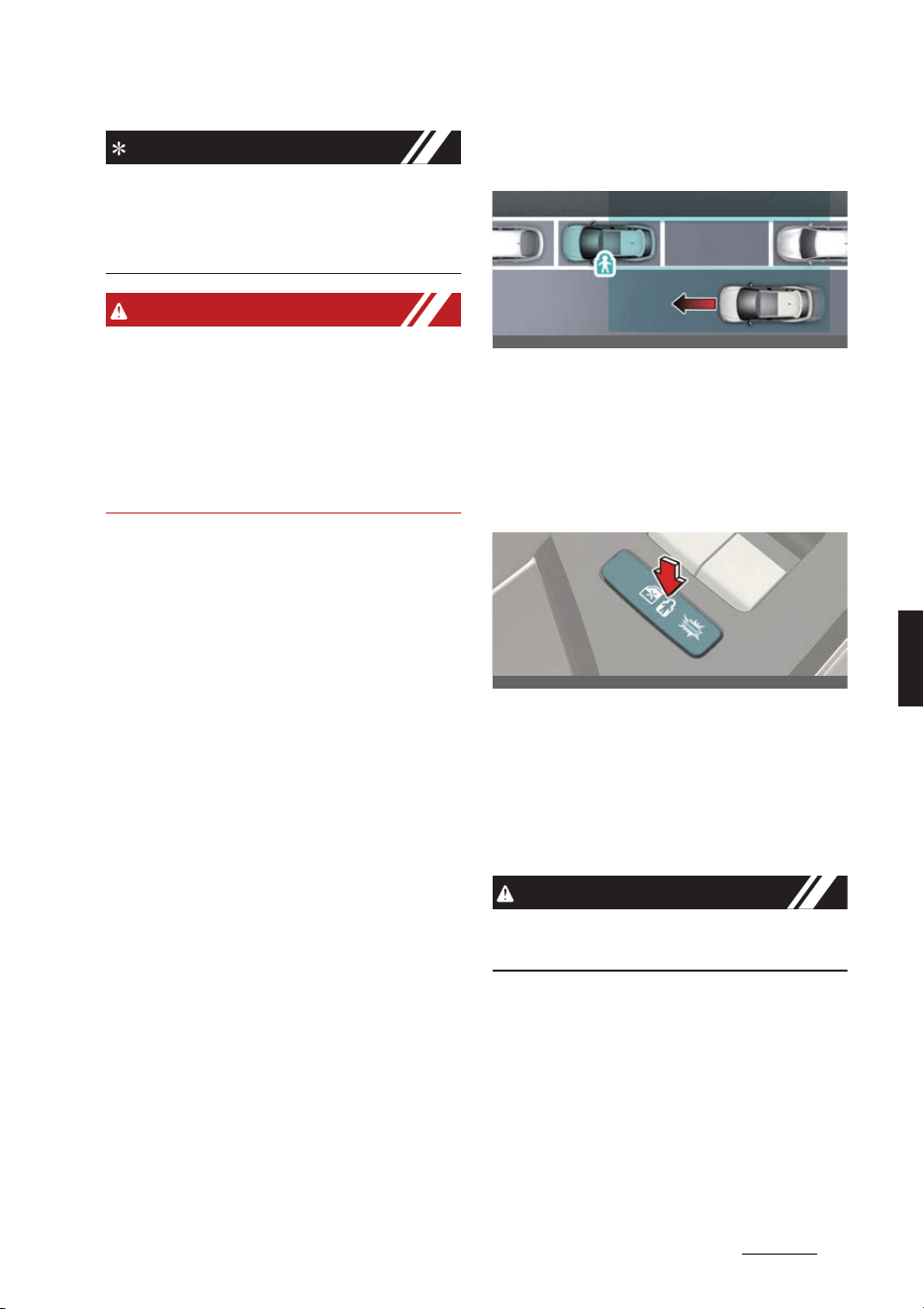
81
6
6
Driving your vehicle Safe Exit Assist (SEA)
NOTICE
For more details on the precautions of
the rear corner radars, refer to "Blind-
Spot Collision-Avoidance Assist (BCA) (if
equipped)" on page 6-67.
WARNING
僅 Safe Exit Warning may not operate
normally if interfered by strong elec
-
tromagnetic waves.
僅 Safe Exit Warning may not operate for
3 seconds after the vehicle is
restarted, or the rear corner radars
are initialized.
Safe Exit Assist (SEA) (if
equipped)
After the vehicle stops, when an
approaching vehicle from the rear area
is detected as soon as a passenger
opens a door, Safe Exit Assist will warn
the driver with a warning message and
an audible warning to help prevent a
collision.
In addition, when the electronic child
safety lock button is in the LOCK posi
-
tion and an approaching vehicle from
the rear area is detected, the electronic
child safety lock button will not unlock
even if the driver presses the button to
prevent the rear doors from opening.
CAUTION
Warning timing may vary depending on
the speed of the approaching vehicle.
OCV051045K
OCV041012L
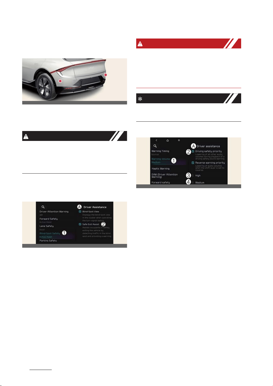
Driving your vehicle
826
Safe Exit Assist (SEA)
Detecting sensor
Rear corner radar
Refer to the picture above for the
detailed location of the detecting sen
-
sors.
CAUTION
For more details on the precautions of
the rear corner radars, refer to "Blind-
Spot Collision-Avoidance Assist (BCA) (if
equipped)" on page 6-67.
Safe Exit Assist settings
SEA (Safe Exit Assist)
A:
Driver assistance
1 Blind-spot safety
2 SEA (Safe Exit Assist)
With the vehicle on, select
Settings
→
Vehicle
→
Driver assistance
→
Blind-
spot safety
→
SEA (Safe Exit Assist)
from the infotainment system screen to
turn on Safe Exit Assist and deselect to
turn off Safe Exit Assist.
WARNING
The driver should always be aware of
unexpected and sudden situations from
occurring. If
SEA (Safe Exit Assist)
is
deselected, Safe Exit Assist cannot assist
you.
NOTICE
If the vehicle is restarted, Safe Exit Assist
will maintain the last setting.
Warning volume
A:
Driver assistance
1 Warning volume
2 Driving safety priority
3 High
4 Medium
5 Low
6 Off
With the vehicle on, Settings
→
Vehi
-
cle
→
Driver assistance
→
Driving
safety
→
Warning volume
on the info
-
tainment system to change the Warning
volume to adjust the Warning volume
levels;
High
,
Medium
,
Low
or
Off
.
If
Driving safety priority
is selected, the
audio volume will temporarily decrease
to warn the driver with the audible warn
-
ing for safe driving.
OCV051025L
OCV041568L
OCVGT042562L
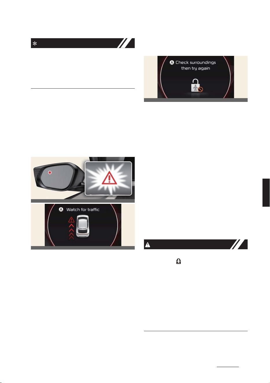
83
6
6
Driving your vehicle Safe Exit Assist (SEA)
NOTICE
僅 If you change the Warning volume,
the Warning volume of other Driver
Assistance systems may change.
僅If
Off
is selected, steering wheel
vibration will not turn off.
Safe Exit Assist operation
Warning and control
Safe Exit Assist warns and controls with
the following actions.
Collision warning when exiting
vehicle
A:
Watch for traffic
僅 The warning light on the side view
mirror will blink and the warning mes
-
sage will appear on the cluster, and an
audible warning will sound.
僅 Safe Exit Assist will warn under the
following circumstances:
- Your vehicle speed: below 3 km/h
(2 mph)
- The speed of the approaching vehi
-
cle from the rear: above 6 km/h (4
mph)
Safe Exit Assist linked with Elec
-
tronic child safety lock
A:
Check surroundings then try again
僅 When Electric child safety lock is oper
-
ating and an approaching vehicle
from the rear area is detected, the
rear doors cannot be unlocked even if
the driver tries to unlock the rear
doors using the electronic child safety
lock button. The warning light on the
outside rearview mirror will blink and
the warning message will appear on
the cluster.
僅 Safe Exit Assist will warn under the
following circumstances:
- Your vehicle speed: below 3 km/h
(2 mph)
- The speed of the approaching vehi
-
cle from the rear: above 6 km/h (4
mph)
CAUTION
If the driver presses the electronic child
lock button ( ) again within 10 seconds
after the warning message appears,
Safe Exit Assist judges that the driver
has unlocked the door and the door will
open regardless of vehicles approach
-
ing. The electronic child safety lock will
turn off (button indicator OFF). Always
check the surroundings before turning
off the electronic child safety lock but
-
ton.
OCV051038L
OCV051142L
OCV051143L
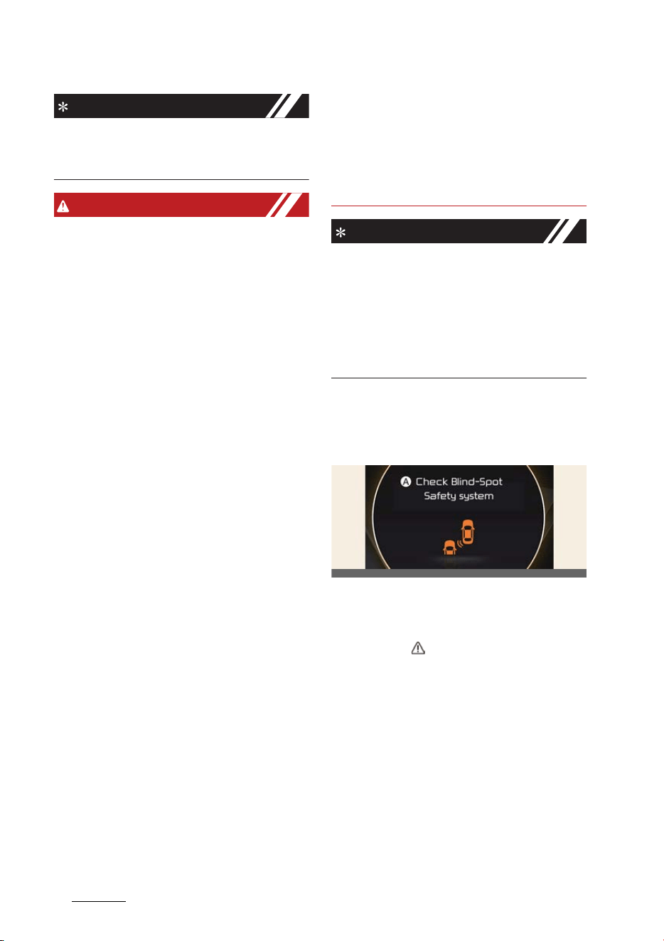
Driving your vehicle
846
Safe Exit Assist (SEA)
NOTICE
If a rear door is opened from the outside,
it will open regardless of Safe Exit Assist
operation.
WARNING
Take the following precautions when
using Safe Exit Assist:
僅 For your safety, change the Settings
after parking the vehicle at a safe
location.
僅 If any other function's warning mes
-
sage is displayed or audible warning
is generated, Safe Exit Assist warning
message may not be displayed and
audible warning may not be gener
-
ated.
僅 You may not hear the warning sound
of Safe Exit Assist if the surrounding is
noisy.
僅 Safe Exit Assist does not operate in all
situations or cannot prevent all colli
-
sions.
僅 Safe Exit Assist may warn the driver
late or may not warn the driver
depending on the road and driving
conditions. Always check vehicle sur
-
roundings.
僅 The driver and passengers are
responsible for accidents that occurs
while exiting the vehicle. Always check
the surroundings before you exit the
vehicle.
僅 Never deliberately operate Safe Exit
Assist. Doing so may lead to serious
injury or death.
僅 Safe Exit Assist does not operate if
there is a problem with Blind-Spot
Collision-Avoidance Assist.
僅 The warning message of Blind-Spot
Collision-Avoidance Assist will appear
when:
- Blind-Spot Collision-Avoidance
Assist sensor or the sensor sur
-
rounding is polluted or covered
- Blind-Spot Collision-Avoidance
Assist fails to warn passengers or
falsely warn passengers
NOTICE
僅 After the vehicle is turned off, Safe
Exit Assist operates for 3 minutes, but
turns off immediately if the doors are
locked.
僅 Images or colors may be displayed
differently depends on the instrument
cluster specifications or theme.
Safe Exit Assist malfunction and
limitations
Safe Exit Assist malfunction
A:
Check Blind-Spot Safety system
When Safe Exit Assist is not working
properly, the warning message will
appear and ( ) warning lights will illumi
-
nate on the cluster, and Safe Exit Assist
will turn off automatically or Safe Exit
Assist will be limited. Have Safe Exit
Assist be inspected by a professional
workshop. Kia recommends visiting an
authorized Kia dealer/service partner.
OCV051139L
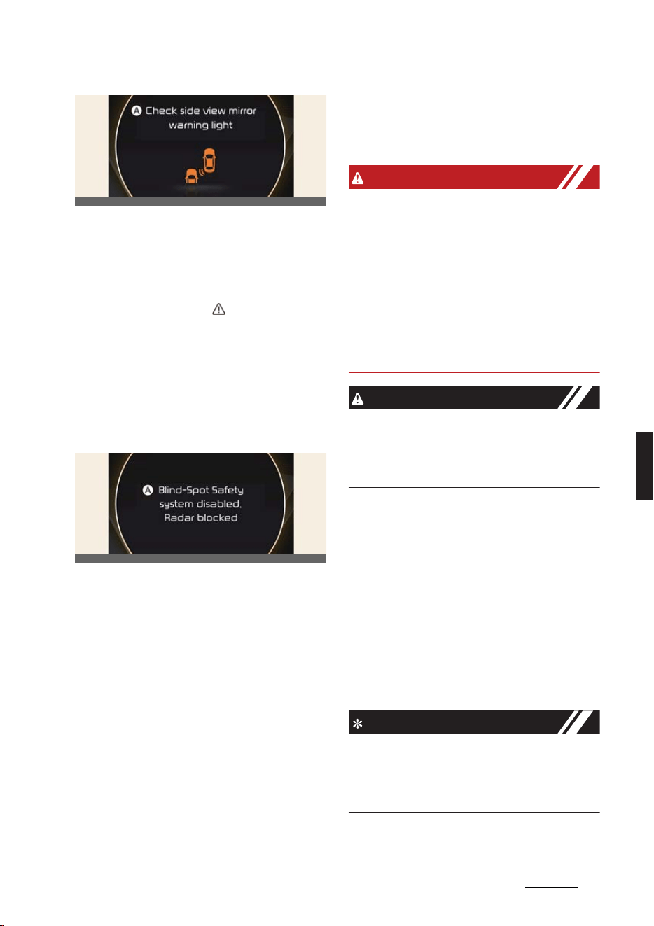
85
6
6
Driving your vehicle Safe Exit Assist (SEA)
A:
Check side view mirror warning
light
When the side view mirror warning light
is not working properly, the warning
message will appear on the cluster for
several seconds, and ( ) warning light
will illuminate on the cluster. Have Safe
Exit Assist be inspected by a profes
-
sional workshop. Kia recommends visit
-
ing an authorized Kia dealer/service
partner.
Safe Exit Assist disabled
A:
Blind-Spot Safety system disabled.
Radar blocked
When the rear bumper around the rear
corner radar or sensor is covered with
foreign material, such as snow or rain, or
installing a trailer or carrier, it can reduce
the detecting performance and tempo
-
rarily limit or disable Safe Exit Assist.
If this occurs, the
Blind-Spot Safety
system disabled. Radar blocked
warn
-
ing message will appear on the cluster.
Safe Exit Assist will operate normally
when such foreign material or trailer, etc.
is removed, and then the vehicle is
restarted.
If Safe Exit Assist does not operate nor
-
mally after it is removed, Kia recom
-
mends visiting an authorized Kia dealer/
service partner.
WARNING
僅 Even though the warning message
does not appear on the cluster, Safe
Exit Assist may not properly operate.
僅 Safe Exit Assist may not properly
operate in an area (e.g., open terrain),
where any substance are not detected
right after the vehicle is turned on, or
when the detecting sensor is blocked
with foreign material right after the
vehicle is turned on.
CAUTION
Turn off Safe Exit Assist to install a
trailer, carrier, other equipment, or
remove the trailer, carrier, etc. to use
Safe Exit Assist.
Limitations of Safe Exit Assist
Safe Exit Assist may not operate nor
-
mally, or Safe Exit Assist may operate
unexpectedly under the following cir
-
cumstances:
僅 Getting out of the vehicle where trees
or grass are overgrown
僅 Getting out of the vehicle where the
road is wet
僅 The approaching vehicle is very fast
or very slow
NOTICE
For more details on the limitations of the
rear corner radar, refer to "Blind-Spot
Collision-Avoidance Assist (BCA) (if
equipped)" on page 6-67.
OCV051140L
OCV051141L
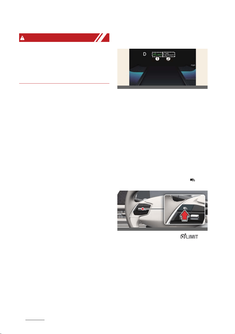
Driving your vehicle
866
Manual Speed Limit Assist (MSLA)
WARNING
僅 Safe Exit Assist may not operate nor
-
mally if interfered by strong electro
-
magnetic waves.
僅 Safe Exit Assist may not operate for 3
seconds after the vehicle is started, or
the rear corner radars are initialized.
Manual Speed Limit Assist
(MSLA)
1
Speed Limit indicator
2
Set speed
You can set the speed limit when you do
not want to drive over a specific speed.
If you drive over the preset speed limit,
the warning function operates (set
speed limit will blink and chime will
sound) until the vehicle speed returns
within the speed limit.
Manual Speed Limit Assist opera
-
tion
Setting speed limit
1. Press and hold Driving Assist ( ) but
-
ton at the desired speed.
The speed limit indicator ( )
light will illuminate on the cluster.
2. Push the + switch up or - switch down,
and release it at the desired speed.
Push the + switch up or - switch down
and hold it. The speed will increase or
decrease to the nearest multiple of
ten (multiple of five in mph) at first,
and then increase or decrease by 10
km/h (5 mph).
OCV041169
OCV051046L
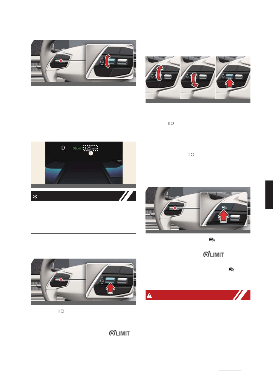
87
6
6
Driving your vehicle Manual Speed Limit Assist (MSLA)
3. The set speed limit (1) will be dis
-
played on the cluster. If you would like
to drive over the preset speed limit,
depress the accelerator pedal fully.
The set speed limit will blink and
chime will sound until you return the
vehicle speed within the speed limit.
NOTICE
When the accelerator pedal is not
depressed beyond the pressure point,
vehicle speed will maintain within the
speed limit.
Temporarily pausing Manual
Speed Limit Assist
Press the ( ) switch to temporarily
pause the set speed limit. The set speed
limit will turn off or become gray color
but the Speed Limit indicator ( )
will stay on.
Resuming Manual Speed Limit
Assist
To resume Manual Speed Limit Assist
after the function was paused, operate
the +, -, ( ) switch.
If you push the + switch up or - switch
down, vehicle speed will be set to the
current speed on the cluster.
If you press the ( ) switch, vehicle
speed will resume to the preset speed.
Turning off Manual Speed Limit
Assist
Press the Driving Assist ( ) button to
turn Manual Speed Limit Assist off. The
Speed Limit indicator ( ) will go
off.
Always press the Driving Assist ( ) but
-
ton to turn Manual Speed Limit Assist off
when not in use.
WARNING
Take the following precautions when
using Manual Speed Limit Assist:
僅 Always set the vehicle speed to the
speed limit in your country.
僅 Keep Manual Speed Limit Assist off
when the function is not in use, to
avoid inadvertently setting a speed.
OCV051047L
OCV041170
OCV051049L
OCV051050L_3
OCV051046L
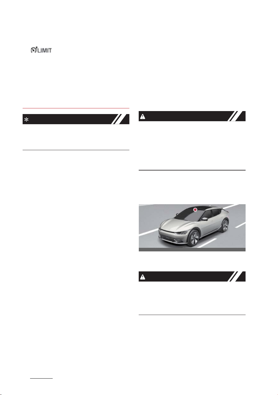
Driving your vehicle
886
Intelligent Speed Limit Assist (ISLA)
Check that the Speed Limit indicator
( ) is off.
僅 Manual Speed Limit Assist does not
substitute for proper and safe driving.
It is the responsibility of the driver to
always drive safely and should always
be aware of unexpected and sudden
situations from occurring. Pay atten
-
tion to the road conditions at all times.
NOTICE
The images or colors may be displayed
differently depending on the specifica
-
tions of the instrument cluster or theme.
Intelligent Speed Limit Assist
(ISLA) (if equipped)
Intelligent Speed Limit Assist uses infor
-
mation from the detected road sign and
navigation system to inform the driver of
the speed limit and additional road signs
of the current road. Also, the function
helps the driver to maintain within the
speed limit of the road.
CAUTION
僅 Intelligent Speed Limit Assist may not
operate properly if the function is
used in other countries.
僅 Update navigation system regularly
for Intelligent Speed Limit Assist to
operate normally.
Detecting sensor
Front view camera
Refer to the picture above for the
detailed location of the detecting sensor.
CAUTION
For more precautions related to the
camera sensor, refer to "Forward Colli
-
sion-Avoidance Assist (FCA) (if
equipped)" on page 6-43.
OCV051017L
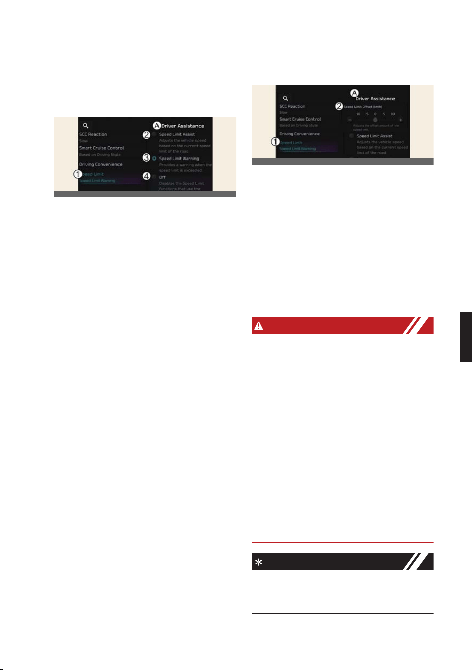
89
6
6
Driving your vehicle Intelligent Speed Limit Assist (ISLA)
Intelligent Speed Limit Assist set
-
tings
Speed limit
A:
Driver assistance
1 Speed limit
2 Speed limit assist
3 Speed limit warning
4 Off
With the vehicle on, select or deselect
Settings
→
Vehicle
→
Driver assis
-
tance
→
Speed limit
from the Settings
menu to set whether or not to use each
function.
僅If
Speed limit Assist
is selected, Intel
-
ligent Speed Limit Assist will inform
the driver of speed limit and addi
-
tional road signs. In addition, Intelli
-
gent Speed Limit Assist will inform the
driver to change set speed of Manual
Speed Limit Assist and/or Smart
Cruise Control to help the driver stay
within the speed limit.
僅If
Speed limit warning
is selected,
Intelligent Speed Limit Assist will
inform the driver of speed limit and
additional road signs. In addition,
Intelligent Speed Limit Assist will warn
the driver when the vehicle is driven
faster than the speed limit. Manual
Speed Limit Assist or Smart Cruise
Control set speed will not be automat
-
ically adjusted. The driver should
adjust the speed manually.
僅If
Off
is selected, Intelligent Speed
Limit Assist will turn off.
Speed limit offset
A:
Driver assistance
1 Speed limit
2 Speed limit offset
(km/h)
With the vehicle on, when
Settings
→
Vehicle
→
Driver assistance
→
Speed
limit
→
Speed limit offset
is selected,
the Speed Limit Offset can be changed.
Speed Limit Warning and Speed Limit
Assist will operate by applying the Speed
Limit Offset setting to the detected
speed limit.
WARNING
僅 For your safety, change the Settings
after parking the vehicle at a safe
location.
僅 Speed Limit Assist function operates
based on the Offset setting added to
the speed limit. If you want to change
the set speed according to the speed
limit, set the offset to
0
.
僅 Speed Limit Warning function warns
the driver when driving speed
exceeds the speed at which the set
Offset is added to speed limit. If you
want Speed Limit Warning to warn
you immediately when the driving
speed exceeds the speed limit, set the
offset to
0
.
NOTICE
The setting of
Speed limit offset
is not
reflected in Navigation-based Smart
Cruise Control (NSCC).
OCV041569L
OCV041570L
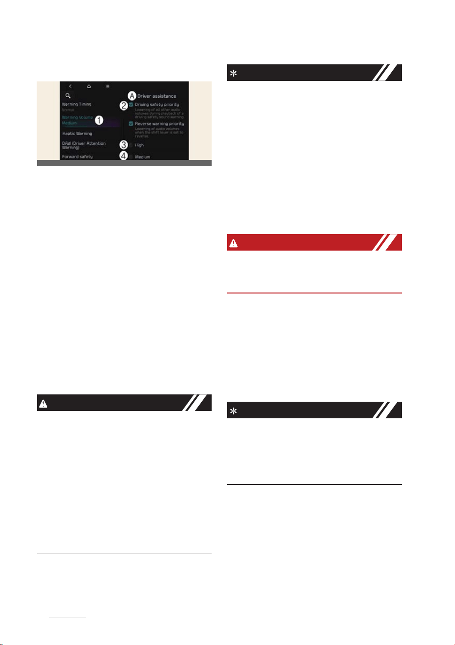
Driving your vehicle
906
Intelligent Speed Limit Assist (ISLA)
Warning volume
A:
Driver assistance
1 Warning volume
2 Driving safety priority
3 High
4 Medium
5 Low
6 Off
With the vehicle on, touch
Settings
→
Vehicle
→
Driver assistance
→
Driving
safety
→
Warning volume
on the info
-
tainment system to change the Warning
volume to adjust the Warning volume
levels;
High
,
Medium
,
Low
or
Off
.
If
Driving safety priority
is selected, the
audio volume will temporarily decrease
to warn the driver with the audible warn
-
ing for safe driving.
CAUTION
僅 The setting of the Warning Timing
and Warning Volume applies to all
functions of Forward Collision-Avoid
-
ance Assist.
僅Even though
Normal
is selected for
Warning Timing, if the front vehicle
suddenly stops, the warning may
seem late.
僅 Select
Late
for Warning Timing when
traffic is light and when driving speed
is slow.
NOTICE
僅 If the vehicle is restarted, Warning vol
-
ume will maintain the last setting.
僅If
Off
is selected, the Warning volume
of Forward Collision-Avoidance Assist
will not turn off, but the volume will
sound as
Low
.
僅If
Off
is selected, steering wheel
vibration will not turn off.
僅 If you change the Warning volume,
the Warning volume of other Driver
Assistance systems may change.
WARNING
For your safety, change the settings
after parking the vehicle at a safe loca
-
tion.
Intelligent Speed Limit Assist
operation
Warning and control
Intelligent Speed Limit Assist will warn
and control the vehicle by 'Displaying
speed limit', 'Warning overspeed' and
'Changing set speed'.
NOTICE
Intelligent Speed Limit Assist warning
and control are described based on the
Offset set to
0
. For details on Offset set
-
ting, refer to "Intelligent Speed Limit
Assist settings" on page 6-89.
OCVGT042562L
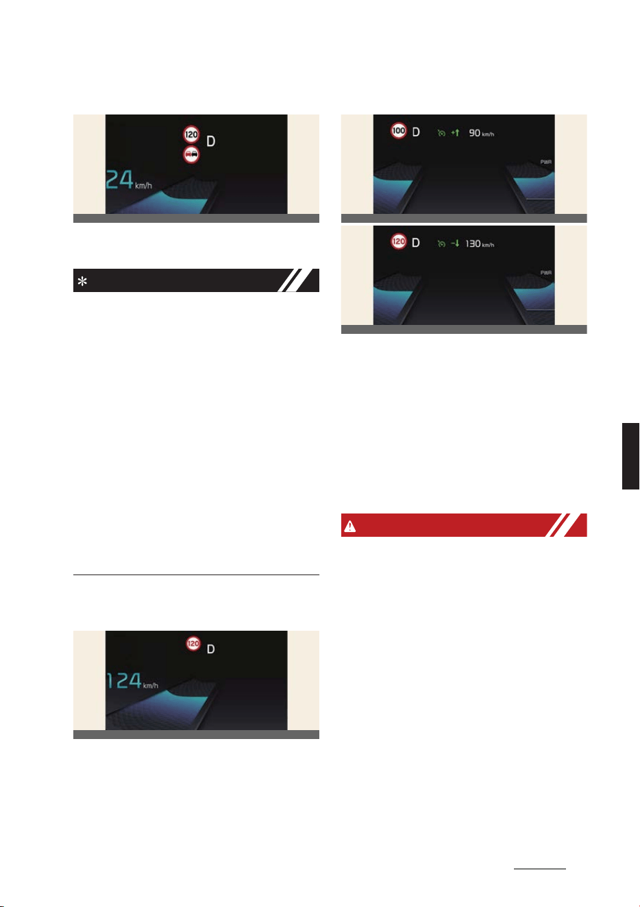
91
6
6
Driving your vehicle Intelligent Speed Limit Assist (ISLA)
Displaying speed limit
Speed limit information is displayed on
the instrument cluster.
NOTICE
僅 If speed limit information of the road
cannot be recognized, '---' sign will be
displayed. Please refer to "Limitations
of Intelligent Speed Limit Assist" if the
road signs are difficult to recognize.
僅 Intelligent Speed Limit Assist provides
additional road sign information in
addition to speed limit. The additional
road sign information provided may
vary according to your country.
僅 Supplementary sign displayed under
the speed limit or overtaking restric
-
tion sign means the conditions under
which the signs must be followed. If
the supplementary sign is not recog
-
nized, it will be displayed as blank.
Warning overspeed
When driving at a speed higher than the
displayed speed limit, the red speed limit
indicator will blink and an audible warn
-
ing sound will sound.
Changing set speed
If the speed limit of the road changes
during the operation of Manual Speed
Limit Assist or Smart Cruise Control, an
arrow in the direction of up or down is
displayed to inform the driver that the
set speed needs to be changed. At this
time, the driver can change the set
speed according to the speed limit by
using the + or - switch on the steering
wheel.
WARNING
僅 If the Offset is set over
0
, the set
speed will change to a higher speed
than the speed limit of the road. If you
want to drive below the speed limit,
set the Offset under
0
or use the -
switch on the steering wheel to lower
the set speed.
僅 Even after changing the set speed
according to the speed limit of the
road, the vehicle can still be driven
over the speed limit. If necessary,
depress the brake pedal to reduce
your driving speed.
僅 If the speed limit of the road is under
30 km/h (20 mph), the set speed
change function will not work.
OCV051146L
OCV051147L
OCV051148L
OCV051149L
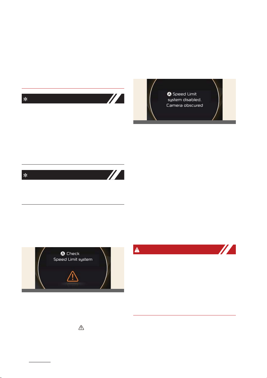
Driving your vehicle
926
Intelligent Speed Limit Assist (ISLA)
僅 Intelligent Speed Limit Assist oper
-
ates using the speed unit in the instru
-
ment cluster set by the driver. If the
speed unit is set to a unit other than
the speed unit used in your country,
Intelligent Speed Limit Assist may not
operate properly.
NOTICE
僅 For more details on function opera
-
tion of Manual Speed Limit Assist,
refer to "Manual Speed Limit Assist
(MSLA)" on page 6-86.
僅 For more details on operation of
Smart Cruise Control, refer to "Smart
Cruise Control (SCC) (if equipped)" on
page 6-104.
NOTICE
The images or colors may be displayed
differently depending on the specifica
-
tions of the instrument cluster or theme.
Intelligent Speed Limit Assist
malfunction and limitations
Intelligent Speed Limit Assist
malfunction
A:
Check Speed Limit system
When Intelligent Speed Limit Assist is not
working properly, the warning message
will appear on the cluster for several sec
-
onds, and the master ( ) warning light
will illuminate on the cluster. If this
occurs, we recommend the function
checked by an authorized Kia dealer/
service partner.
Intelligent Speed Limit Assist dis
-
abled
A:
Speed limit system disabled. Cam
-
era obscured
When the front windshield where the
front view camera is located is covered
with foreign material, such as snow or
rain, it can reduce the detecting perfor
-
mance and temporarily limit or disable
Intelligent Speed Limit Assist.
If this occurs, the warning message will
appear on the cluster. The function will
operate normally when snow, rain or for
-
eign material is removed.
If Intelligent Speed Limit Assist does not
operate normally after it is removed, we
recommend the function checked by an
authorized Kia dealer/service partner.
WARNING
僅 Even though the warning message or
warning light does not appear on the
cluster, Intelligent Speed Limit Assist
may not operate properly.
僅 Intelligent Speed Limit Assist may not
operate normally if the vehicle is
turned off and restarted with the front
view camera covered.
OCV051150L
OCV051151L

93
6
6
Driving your vehicle Intelligent Speed Limit Assist (ISLA)
Limitations of Intelligent Speed
Limit Assist
Intelligent Speed Limit Assist may not
operate normally, or the function may
operate unexpectedly under the follow
-
ing circumstances:
僅 The road sign is contaminated or
indistinguishable
- The road sign is difficult to see due
to bad weather, such as rain, snow,
fog, etc.
- The road sign is not clear or dam
-
aged
- The road sign is partially obscured
by surrounding objects or shadow
- A road sign near the road you are
driving is detected
僅 The road signs do not conform to the
standard
- The text or picture on the road sign
is different from the standard
- The road sign is installed between
the main line and the exit road or
between diverging roads
- A conditional road sign is not
installed with a sign located on the
road to enter or exit
- A sign is attached to another vehi
-
cle
僅 The distance between the vehicle and
the road signs is too far
僅 The vehicle encounters illuminating
road signs
僅 Intelligent Speed Limit Assist incor
-
rectly recognizes numbers in the
street signals or other signs as the
speed limit
僅 The minimum speed limit sign is on
the road
僅 The brightness changes suddenly, for
example when entering or exiting a
tunnel or passing under a bridge
僅 Headlamps are not used or the bright
-
ness of the headlamps are weak at
night or in the tunnel
僅 Road signs are difficult to recognize
due to the reflection of sunlight, street
lights, or oncoming vehicles
僅 The navigation information or GPS
information contain errors.
僅 The driver does not follow the guide
of the navigation.
僅 The driver is driving a new road that is
not in the navigation system yet.
僅 The field of view of the Front view
camera is obstructed by sun glare
僅 Driving on a road that is sharply
curved or continuously curved
僅 Driving through speed bumps, or driv
-
ing up and down or left to right on
steep inclines
僅 The vehicle is shaking heavily
僅 There is an error in the navigation
map information or GPS information
僅 The driver is not driving along the
navigation guide route
僅 Driving on a newly opened road
WARNING
僅 Intelligent Speed Limit Assist is a sup
-
plemental function that helps the
driver to comply with the speed limit
on the road, and may not display the
correct speed limit or control the driv
-
ing speed properly.
僅 Always set the vehicle speed to the
speed limit in your country.
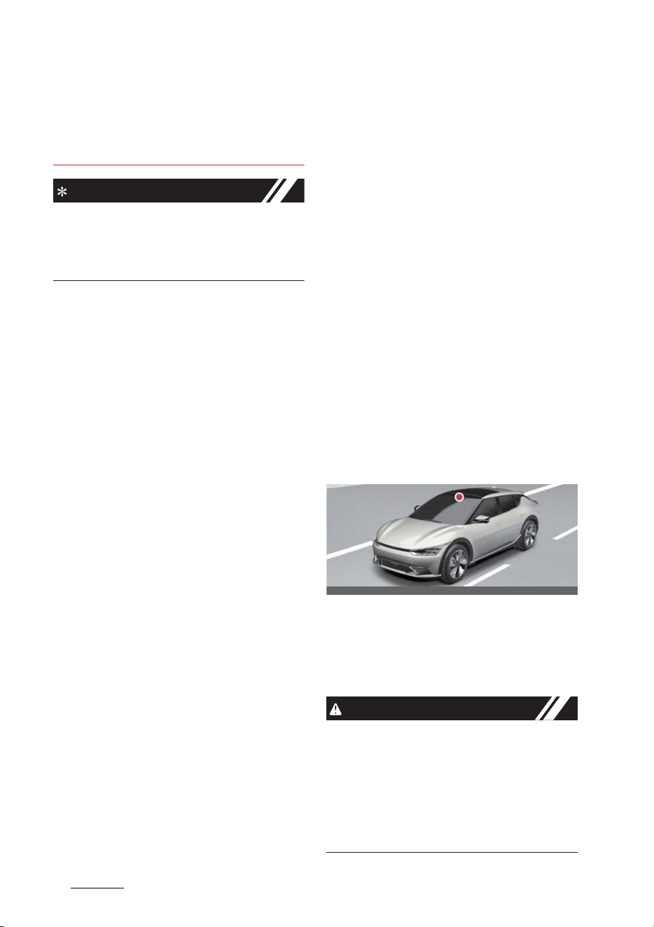
Driving your vehicle
946
Driver Attention Warning (DAW)
僅 Intelligent Speed Limit Assist may not
operate for 15 seconds after the vehi
-
cle is started, or the front view camera
is initialized.
NOTICE
For more details on the limitations of the
front view camera, refer to "Forward Col
-
lision-Avoidance Assist (FCA) (if
equipped)" on page 6-43.
Driver Attention Warning
(DAW) (if equipped)
Basic function
Driver Attention Warning will help deter
-
mine the driver's attention level by ana
-
lyzing driving pattern, driving time, etc.
while vehicle is being driven. Driver
Attention Warning will recommend a
break when the driver's attention level
falls below a certain level.
Leading vehicle departure alert
function
Leading Vehicle Departure Alert function
will inform the driver when the front
vehicle departs from a stop.
Detecting sensor
Front view camera
The front view camera is used to detect
driving patterns and front vehicle depar
-
ture while vehicle is being driven.
Refer to the picture above for the
detailed location of the detecting sensor.
CAUTION
Always keep the front view camera in
good condition to maintain optimal per
-
formance of Driver Attention Warning.
For more details on the precautions of
the front view camera, refer to "Forward
Collision-Avoidance Assist (FCA) (if
equipped)" on page 6-43.
OCV051017L

95
6
6
Driving your vehicle Driver Attention Warning (DAW)
Driver Attention Warning set
-
tings
DAW (Driver Attention Warning)
A:
Driver assistance
1 DAW (Driver Attention Warning)
2 Inattentive driving warning
3 Safety Notice Call
With the vehicle on, select or deselect
Settings
→
Vehicle
→
Driver assis
-
tance
→
DAW (Driver Attention Warn
-
ing)
from the infotainment system
screen to set whether or not to use each
function.
僅 Inattentive Driving Warning: Driver
Attention Warning will inform the
driver the driver's attention level and
will recommend taking a break when
the level falls below a certain level.
NOTICE
Whenever the vehicle is turned on, Inat
-
tentive Driving Warning will always turn
on. (For Europe, Australia, Russia)
Leading Vehicle Departure Alert
A:
Driver assistance
1 DAW (Driver Attention Warning)
2 Leading Vehicle Departure Alert
Leading Vehicle Departure Alert: The
function will inform the driver when the
front vehicle departs from a stop.
Warning timing
A:
Driver assistance
1 Warning timing
2 Normal
3 Late
With the vehicle on, select
Settings
→
Vehicle
→
Driver assistance
→
Warn
-
ing timing
from the infotainment sys
-
tem screen to change the initial warning
activation time for Driver Attention
Warning.
僅
Normal
: Use in a normal driving envi
-
ronment. If Driver Attention Warning
operates too sensitive, set the warning
timing to
Late
.
僅
Late
: The warning timing will be late
NOTICE
If you change the Warning Timing, the
warning time of other Driver Assistance
systems may change. If the vehicle is
restarted, Driver Warning Time will
maintain the last setting.
OCV041571L
OCV041572L
OCVGT042587L
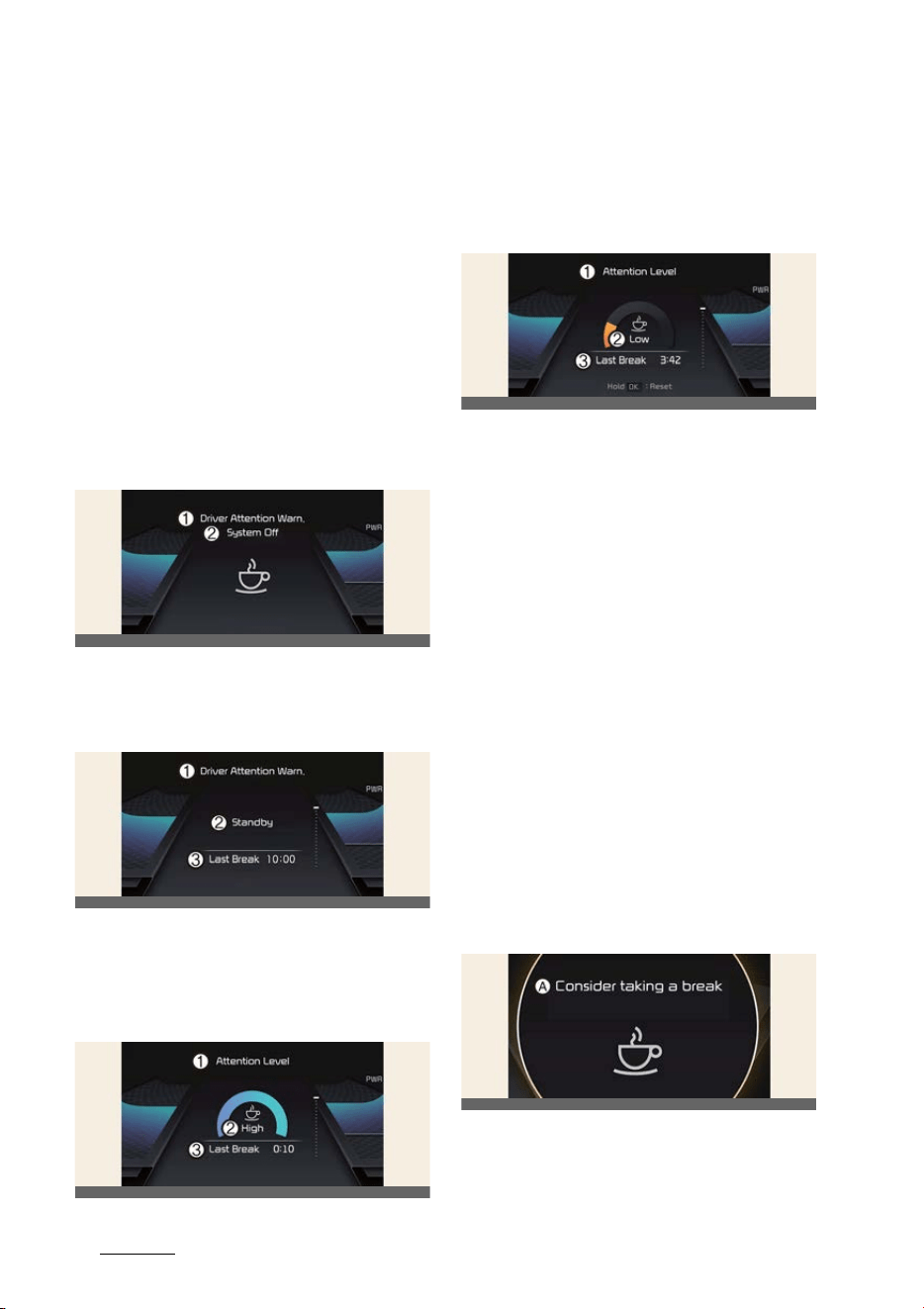
Driving your vehicle
966
Driver Attention Warning (DAW)
Driver Attention Warning opera
-
tion
Basic function
Display and warning
The basic functions of the Driver Atten
-
tion Warning include:
僅 Attention Level
僅 Consider taking a break
Attention level
Function off
1 Driver Attention Warning
2 System Off
Standby/Disabled
1 Driver Attention Warning
2 Standby
3 Last Break
Attentive driving
1 Attention Level
2 High
3 Last Break
Inattentive driving
1 Attention Level
2 Low
3 Last Break
The driver's attention level is displayed
on the scale of 1 to 5. The lower the level
is, the more inattentive the driver is. The
level decreases when the driver does not
take a break for a certain period of time.
Driver Attention Warning (DAW) oper
-
ates under the following conditions:
僅 The vehicle speed: Approximately
0~210 km/h (0~130 mph).
When the
Inattentive driving warning
is deselected from the Settings menu,
System Off
is displayed.
When vehicle speed is not within the
operating speed, the message
Standby
will be displayed.
Taking a break
A:
Consider taking a break
The warning message will appear on the
cluster and an audible warning will
OCV051152L
OCV051153L
OCV051154L
OCV051252L
OCV051156L
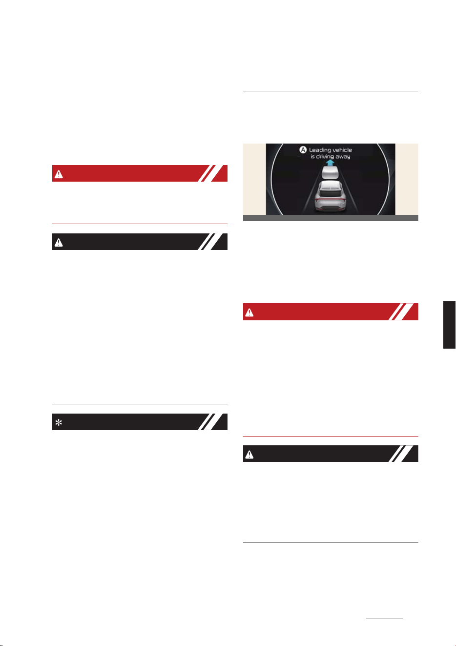
97
6
6
Driving your vehicle Driver Attention Warning (DAW)
sound to suggest that the driver take a
break, when the driver's attention level is
below 1.
Driver Attention Warning will not sug
-
gest a break when the total driving time
is shorter than 10 minutes or 10 minutes
has not passed after the last break was
suggested.
WARNING
For your safety, change the Settings
after parking the vehicle at a safe loca
-
tion.
CAUTION
僅 Driver Attention Warning may suggest
a break depending on the driver's
driving pattern or habits, even if the
driver doesn't feel fatigued.
僅 Driver Attention Warning is a supple
-
mental function and may not be able
to determine whether the driver is
inattentive.
僅 The driver who feels fatigued should
take a break at a safe location, even
though there is no break suggestion
by Driver Attention Warning.
NOTICE
僅 For more details on setting the instru
-
ment cluster, refer to "Instrument
cluster" on page 5-45.
僅 Driver Attention Warning will reset the
last break time to 00:00 in the follow
-
ing situations:
- The vehicle is turned off
- The driver unfastens the seat belt
and opens the driver's door.
- The vehicle is stopped for more
than 10 minutes.
僅 When the driver resets Driver Atten
-
tion Warning, the last break time is set
to 0:00 and the driver's attention level
is set to High.
Leading vehicle departure alert
function
A:
Leading vehicle is driving away
When the front vehicle departs from a
stop, Leading Vehicle Departure Alert
will inform the driver by displaying the
warning message on the cluster and an
audible warning will sound.
WARNING
僅 If any other function's warning mes
-
sage is displayed or audible warning
is generated, Leading Vehicle Depar
-
ture Alert warning message may not
be displayed and audible warning
may not be generated.
僅 The driver should hold the responsi
-
bility to safely drive and control the
vehicle.
CAUTION
僅 Leading Vehicle Departure Alert is a
supplemental function and may not
alert the driver whenever the front
vehicle departs from a stop.
僅 Always check the front of the vehicle
and road conditions before departure.
OCV051157L
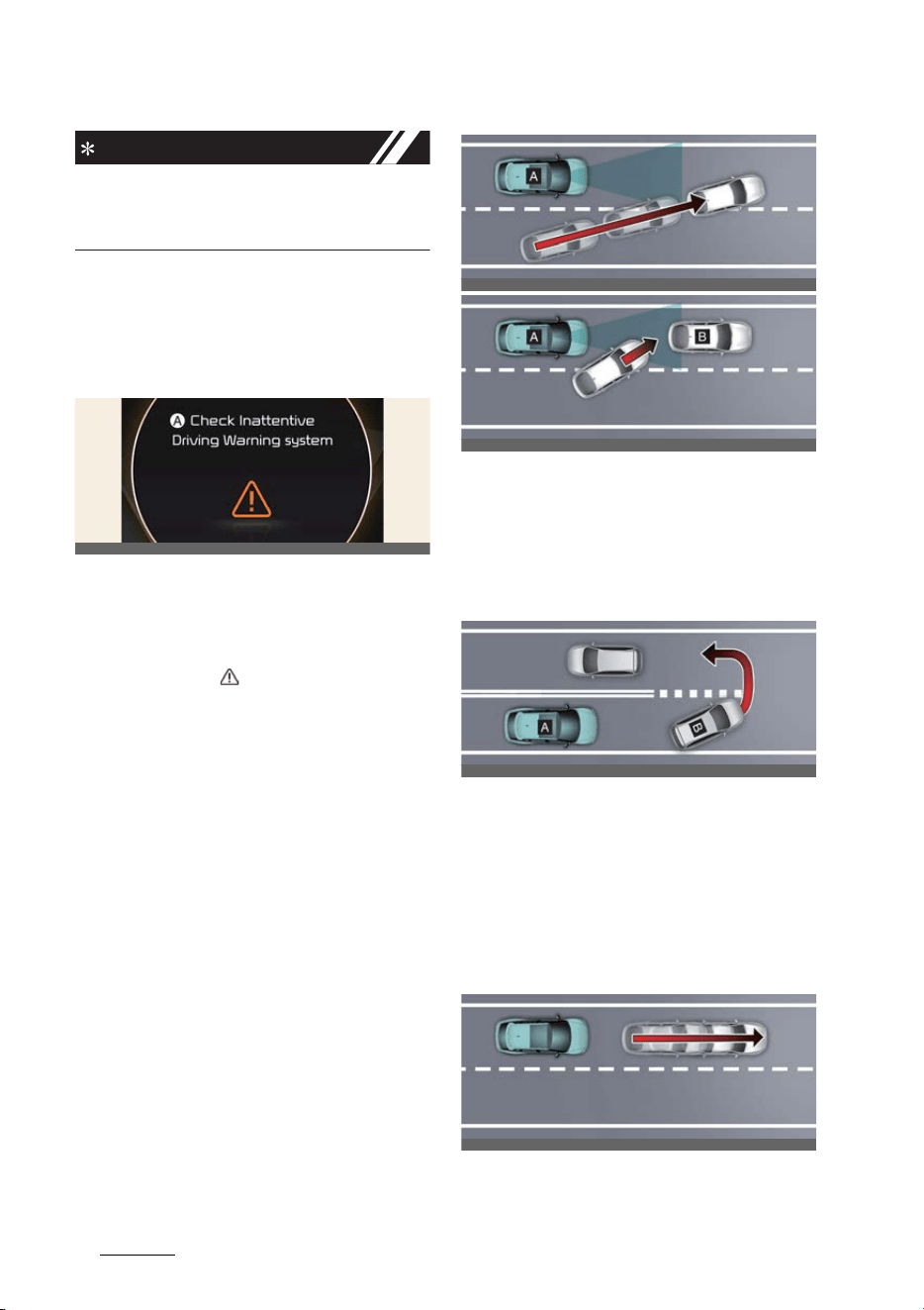
Driving your vehicle
986
Driver Attention Warning (DAW)
NOTICE
The images or colors may be displayed
differently depending on the specifica
-
tions of the instrument cluster or theme.
Driver Attention Warning mal
-
function and limitations
Driver Attention Warning mal
-
function
A:
Check Inattentive Driving Warning
system
When Driver Attention Warning is not
working properly, the warning message
will appear and ( ) warning lights will
illuminate on the cluster. If this occurs,
have Driver Attention Warning be
inspected by a professional workshop.
Kia recommends visiting an authorized
Kia dealer/service partner.
Limitations of Driver Attention
Warning
Driver Attention Warning may not work
properly in the following situations:
僅 The vehicle is driven violently
僅 The vehicle intentionally crosses over
lanes frequently
僅 The vehicle is controlled by Driver
Assistance system, such as Lane
Keeping Assist
Leading vehicle departure alert
function
僅 When the vehicle cuts in
[A]: Your vehicle, [B]: Front vehicle
If a vehicle cuts in front of your vehi
-
cle, Leading Departure Alert may not
operate properly.
僅 When the vehicle ahead sharply
steers
[A]: Your vehicle, [B]: Front vehicle
If the vehicle in front makes a sharp
turn, such as to turn left or right or
make a U- turn, etc., Leading Vehicle
Departure Alert may not operate
properly.
僅 When the vehicle ahead abruptly
departures
OCV051158L
OCV051051L
OCV051052L
OCV051053L
OCV051054L
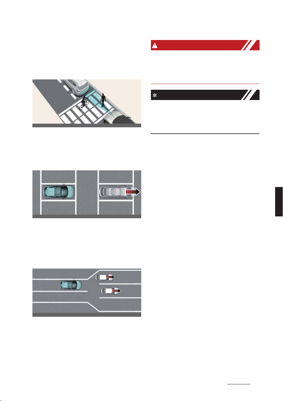
99
6
6
Driving your vehicle Driver Attention Warning (DAW)
If the vehicle in front abruptly depar
-
tures, Leading Vehicle Departure Alert
may not operate properly.
僅 When a pedestrian or bicycle is
between you and the vehicle ahead
If there is a pedestrian(s) or bicycle(s)
in between you and the vehicle in
front, Leading Vehicle Departure Alert
may not operate properly.
僅 When in a parking lot
If a vehicle parked in front drives
away from you, Leading Vehicle
Departure Alert may alert you that the
parked vehicle is driving away.
僅 When driving at a tollgate or intersec
-
tion, etc.
If you pass a tollgate or intersection
with lots of vehicles or you drive
where lanes are merged or divided
frequently, Leading Vehicle Departure
Alert may not operate properly.
WARNING
Driver Attention Warning may not oper
-
ate for 15 seconds after the vehicle is
started, or the front view camera is ini
-
tialized.
NOTICE
For more details on the precautions of
the front view camera, refer to "Forward
Collision-Avoidance Assist (FCA) (if
equipped)" on page 6-43.
OCV051055L
OCV051056L
OCV051057L
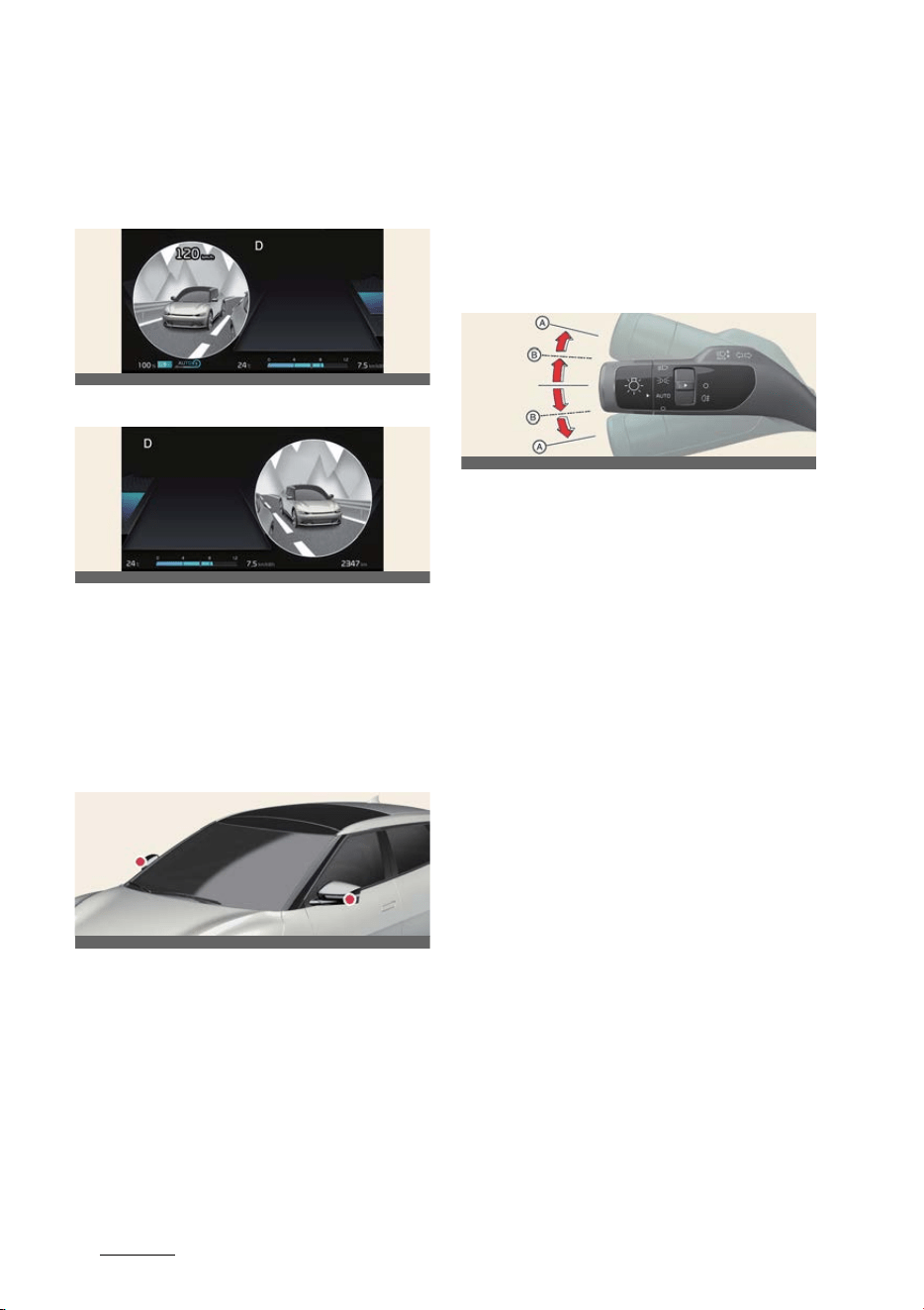
Driving your vehicle
1006
Blind-Spot View Monitor (BVM)
Blind-Spot View Monitor
(BVM) (if equipped)
Left side
Right side
Blind-Spot View Monitor displays the
rear blind spot area of the vehicle in the
cluster when the turn signal is turned on
to help safely change lanes.
Detecting sensor
Wide-side view camera
(camera located at bottom of the mirror)
Refer to the picture above for the
detailed location of the detecting sen
-
sors.
Blind-Spot View Monitor settings
Blind-Spot View
With the vehicle on, select
Settings
→
Vehicle
→
Driver assistance
→
Blind-
spot safety
→
Blind-spot view
from the
infotainment system screen to turn on
Blind-Spot View Monitor and deselect to
turn off the function.
Blind-Spot View Monitor opera
-
tion
Turn signal lever
Blind-Spot View Monitor will turn on and
off when the turn signal is turned on and
off.
Blind-Spot View Monitor
Operating conditions
僅 When the left or right turn signal turns
on, the image on the instrument clus
-
ter will turn on.
Off conditions
Blind-Spot View Monitor will turn off
when one of the following conditions are
satisfied:
僅 When the turn signal is turned off.
僅When the hazard warning flasher is
on.
僅 When other important warning is dis
-
played on the instrument cluster.
Blind-Spot View Monitor mal
-
function
When Blind-Spot View Monitor is not
working properly, or the cluster display
flickers, or the camera image does not
display normally, have Blind-Spot View
Monitor be inspected by a professional
OCV051250L
OCV051251L
OCV051058L
OCV051059L
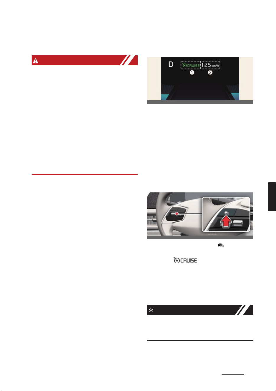
101
6
6
Driving your vehicle Cruise Control (CC)
workshop. Kia recommends visiting an
authorized Kia dealer/service partner.
WARNING
僅 The image shown on the cluster may
differ from the actual distance of the
object. Make sure to directly check the
vehicle's surroundings for safety.
僅 If the camera lens is covered with for
-
eign material, the Blind-Spot View
Monitor may not operate normally.
Always keep the camera lens clean.
However, do not use chemical sol
-
vents such as strong detergents con
-
taining high alkaline or volatile
organic solvents (gasoline, acetone
etc.). This may damage the camera
lens.
Cruise Control (CC) (if
equipped)
1
Cruise indicator
2
Set speed
Cruise Control will allow you to drive at
speeds above 30 km/h (20 mph) without
depressing the accelerator pedal.
Cruise Control operation
To set speed
1. Accelerate to the desired speed,
which must be more than 30 km/h
(20 mph).
2. Press the Driving Assist ( ) button at
the desired speed. The set speed and
Cruise ( ) indicator will illumi
-
nate on the cluster.
3. Release the accelerator pedal.
Vehicle speed will maintain the set
speed even when The accelerator
pedal must not be pressed.
NOTICE
On a steep sloped road, the vehicle may
slightly slow down or speed up while
driving uphill or downhill.
OCV051161L
OCV051046L
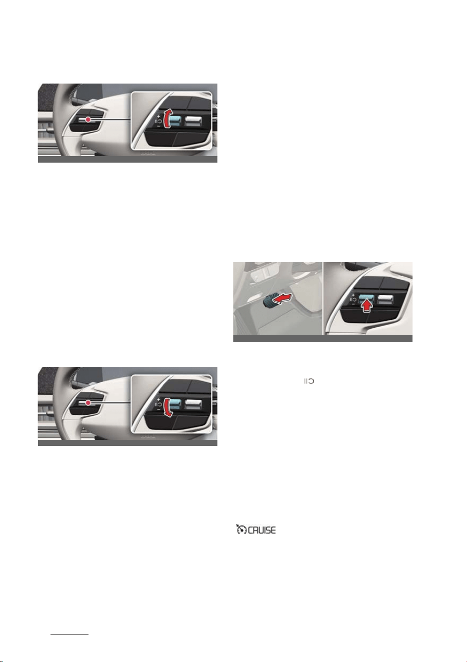
Driving your vehicle
1026
Cruise Control (CC)
To increase set speed
僅Push the + switch up and release it
immediately. The set speed will
increase by 1 km/h (1 mph) each time
the switch is operated in this manner.
僅 Push the + switch up and hold it while
monitoring the set speed on the clus
-
ter. The set speed will increase to the
nearest multiple of ten (multiple of
five in mph) at first, and then increase
by 10 km/h (5 mph) each time the
switch is operated in this manner.
Release the switch when the desired
speed is shown and the vehicle will
accelerate to that speed.
To decrease set speed
僅 Push the - switch down and release it
immediately. The set speed will
decrease by 1 km/h (1 mph) each time
the switch is operated in this manner.
僅 Push the - switch down and hold it
while monitoring the set speed on the
cluster. The set speed will decrease to
the nearest multiple of ten (multiple of
five in mph) at first, and then
decrease by 10 km/h (5 mph) each
time the switch is operated in this
manner.
Release the switch at the speed you
want to maintain.
To temporarily accelerate
If you want to speed up temporarily
when Cruise Control is on, depress the
accelerator pedal.
To return to the set speed, take your foot
off the accelerator pedal.
If you push the + switch up or - switch
down at increased speed, the cruising
speed will be set to the current
increased speed.
To temporarily pause Cruise Con
-
trol
Cruise Control will be paused when:
僅 Depressing the brake pedal.
僅 Pressing the ( ) button.
僅 Shifting the gear to N (Neutral).
僅 Decreasing vehicle speed to less than
approximately 30 km/h (20 mph).
僅 Increasing vehicle speed to more than
approximately 190 km/h (120 mph)
僅 Operating the electronic parking
brake system
EPB
.
僅 ESC (Electronic Stability Control) is
operating.
The set speed will turn off but the Cruise
( ) indicator will stay on.
OCV051248L
OCV051249L
OCV051224L_2
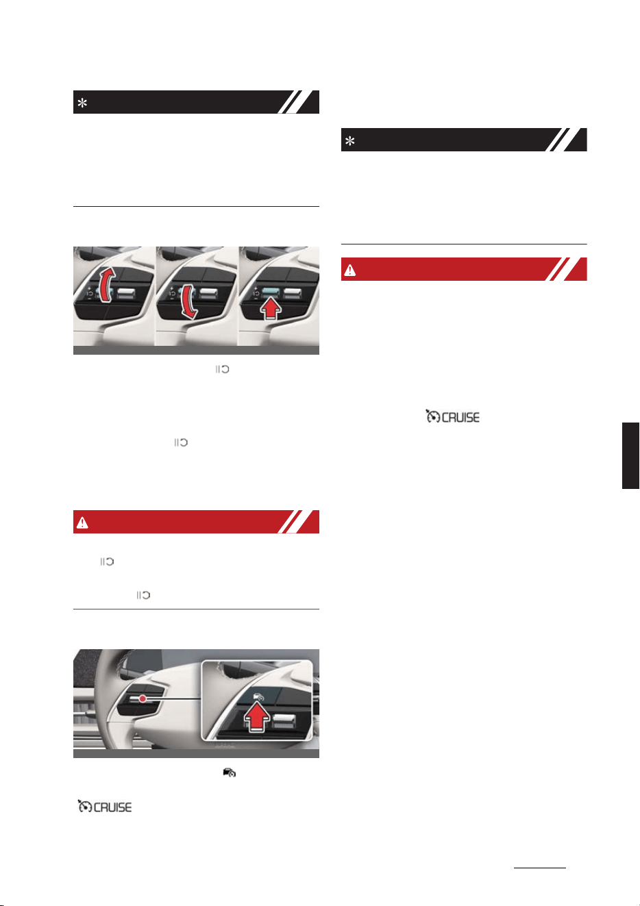
103
6
6
Driving your vehicle Cruise Control (CC)
NOTICE
If Cruise Control pauses during a situa
-
tion that is not mentioned, have the
vehicle be inspected by a professional
workshop. Kia recommends visiting an
authorized Kia dealer/service partner.
To resume Cruise Control
Push the +, - switch or ( ) button.
If you push the + switch up or - switch
down, vehicle speed will be set to the
current speed on the cluster.
If you press the ( ) button, vehicle
speed will resume to the preset speed.
Vehicle speed must be above 30 km/h
(20 mph) for Cruise Control to resume.
WARNING
Check the driving condition before using
the ( ) button. Driving speed may
sharply increase or decrease when you
press the ( ) button.
To turn off Cruise Control
Press the Driving Assist ( ) button to
turn Cruise Control off. The Cruise
( ) indicator will go off.
Always press the Driving Assist button to
turn Cruise Control off when not in use.
NOTICE
If your vehicle is equipped with Manual
Speed Limit Assist, press and hold the
Driving Assist button to turn off Cruise
Control. However, Manual Speed Limit
Assist will turn on.
WARNING
Take the following precautions when
using Cruise Control:
僅 Always set the vehicle speed under
the speed limit in your country.
僅 Keep Cruise Control off when the
function is not in use, to avoid inad
-
vertently setting a speed. Check that
the Cruise ( ) indicator is off.
僅 Cruise Control does not substitute for
proper and safe driving. It is the
responsibility of the driver to always
drive safely and should always be
aware of unexpected and sudden sit
-
uations from occurring.
僅 Always drive cautiously to prevent
unexpected and sudden situations
from occurring. Pay attention to the
road conditions at all times.
僅 Do not use Cruise Control when it may
be unsafe to keep the vehicle at a
constant speed:
- When driving in heavy traffic, or
when traffic conditions make it dif
-
ficult to drive at a constant speed
- When driving on rainy, icy, or snow-
covered roads
- When driving on hilly or windy
roads
- When driving in windy areas
OCV051050L_3
OCV051046L
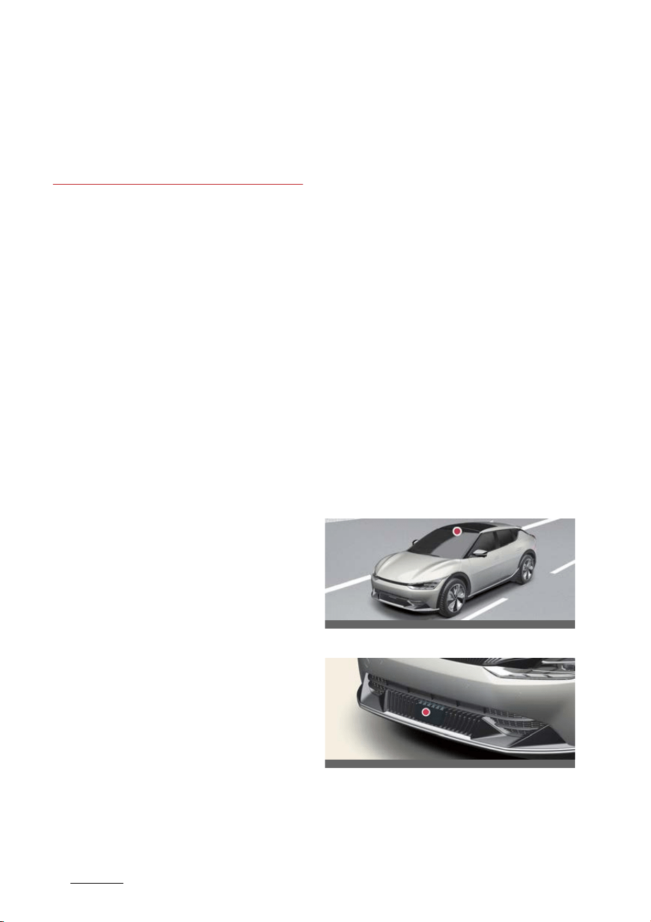
Driving your vehicle
1046
Smart Cruise Control (SCC)
- When driving with limited view
(possibly due to bad weather, such
as fog, snow, rain and sandstorm)
僅 Do not use Cruise Control when tow
-
ing a trailer.
Smart Cruise Control (SCC) (if
equipped)
Smart Cruise Control is designed to
detect the vehicle ahead and help main
-
tain the desired speed and minimum
distance with the vehicle ahead.
Overtaking Acceleration Assist
While Smart Cruise Control is operating,
if the function judges that the driver is
determined to overtake the vehicle in
front, acceleration will be assisted.
Based on Driving Style (if
equipped)
Smart Cruise Control will operate based
on the driver's driving style, such as
inter-vehicle distance, acceleration,
reaction speed.
Detecting sensor
Front view camera
Front radar
OCV051017L
OCV051005L
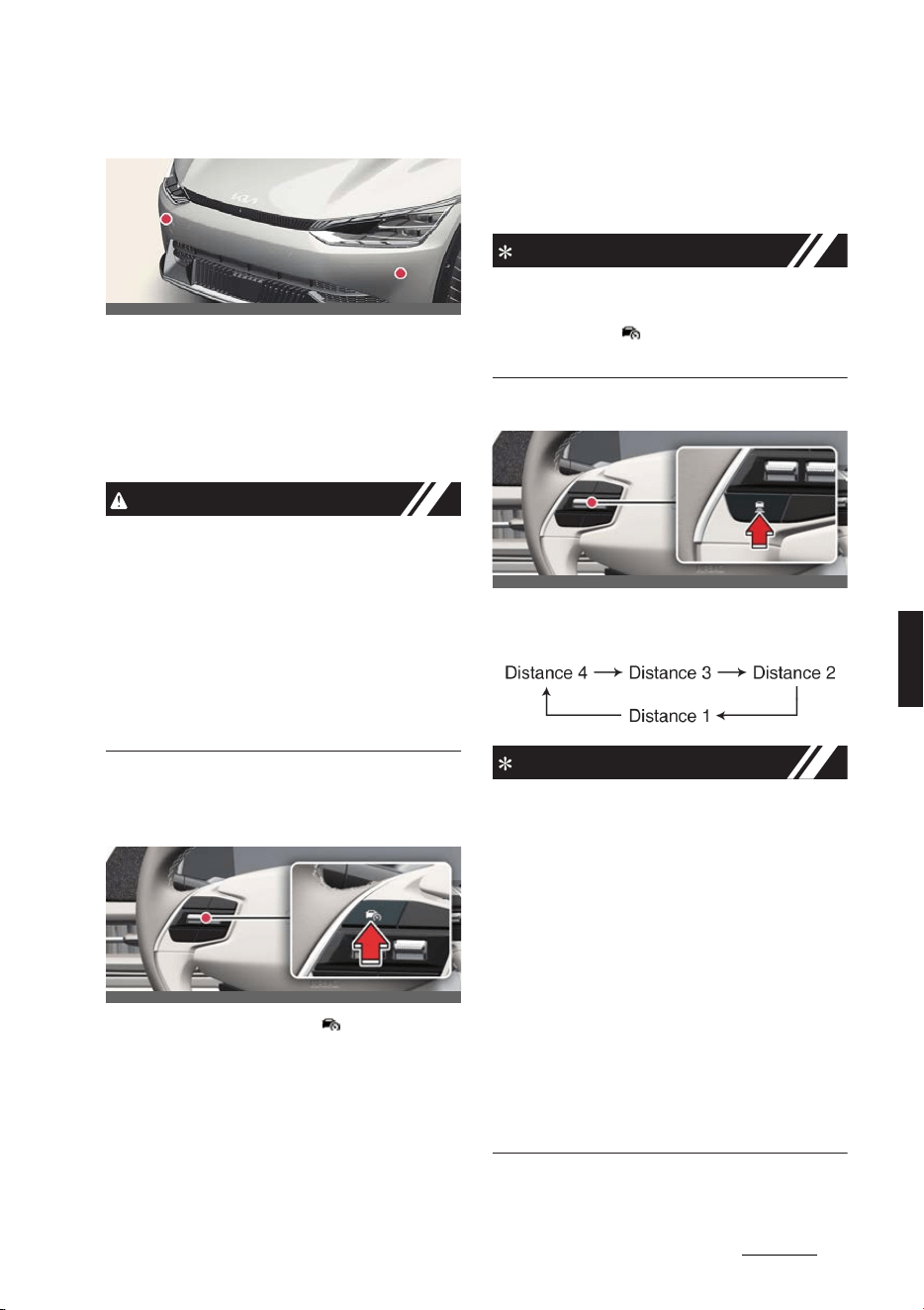
105
6
6
Driving your vehicle Smart Cruise Control (SCC)
Front corner radar (if equipped)
The front view camera, front radar, and
front corner radars (if equipped) are
used as a detecting sensor to detect the
vehicles in front.
Refer to the picture above for the
detailed location of the detecting sensor.
CAUTION
僅 Always keep the front view camera
and front radar in good condition to
maintain optimal performance of
Smart Cruise Control.
僅 For more details on the precautions of
the front view camera and front radar,
refer to "Forward Collision-Avoidance
Assist (FCA) (if equipped)" on page 6-
43.
Smart Cruise Control settings
To turn on Smart Cruise Control
Press the Driving Assist ( ) button to
turn on the function. The speed will be
set to the current speed on the cluster.
僅 If there is no vehicle in front of you,
the set speed will be maintained.
僅 If there is a vehicle in front of you, the
speed may be adjusted to maintain
the distance to the vehicle ahead. If
the vehicle ahead accelerates, your
vehicle will travel at a steady cruising
speed after accelerating to the set
speed.
NOTICE
If your vehicle speed is between 0~30
km/h (0~20 mph) when you press the
Driving Assist ( ) button, the set speed
will be set to 30 km/h (20 mph).
To set vehicle distance
Each time the button is pressed, the
vehicle distance changes as follows:
NOTICE
僅 If you drive at 90 km/h (56 mph), the
distance is maintained as follows:
- Distance 4 - approximately 52.5 m
(172 ft.)
- Distance 3 - approximately 40 m
(130 ft.)
- Distance 2 - approximately 32.5 m
(106 ft.)
- Distance 1 - approximately 25 m (82
ft.)
僅 The distance is set to the last set dis
-
tance when the vehicle is restarted, or
when Smart Cruise Control was tem
-
porarily canceled.
OCV051024L
OCV051046L
OCV051060L
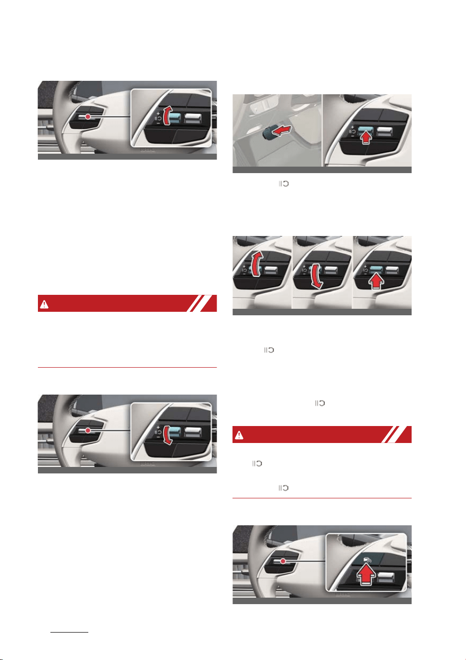
Driving your vehicle
1066
Smart Cruise Control (SCC)
To increase set speed
Push the + switch up and release it
immediately. The set speed will increase
by 1 km/h (1 mph) each time the switch
is operated in this manner.
僅Push the + switch up and hold it. The
set speed will increase by 10 km/h (5
mph) each time the switch is operated
in this manner.
僅 You can increase the set speed to 200
km/h (120 mph).
WARNING
Check the driving condition before using
the + switch. Driving speed may sharply
increase when you push up and hold the
+ switch.
To decrease set speed
Push the - switch down and release it
immediately. The set speed will decrease
by 1 km/h (1 mph) each time the switch
is operated in this manner.
僅 Push the - switch down and hold it.
The set speed will decrease by 10 km/
h (5 mph) each time the switch is
operated in this manner.
僅 You can decrease the set speed to 30
km/h (20 mph).
To temporarily cancel Smart
Cruise Control
Press the ( ) switch or depress the
brake pedal to temporarily cancel Smart
Cruise Control.
To resume Smart Cruise Control
To resume Smart Cruise Control after
the function was canceled, operate the
+, - or ( ) switch.
僅 If you push the + switch up or - switch
down, vehicle speed will be set to the
current speed on the cluster.
僅 If you push the ( ) switch, vehicle
speed will resume to the preset speed.
WARNING
Check the driving condition before using
the ( ) switch. Driving speed may
sharply increase or decrease when you
press the ( ) switch.
To turn off Smart Cruise Control
OCV051248L
OCV051249L
OCV051224L_2
OCV051050L_3
OCV051046L
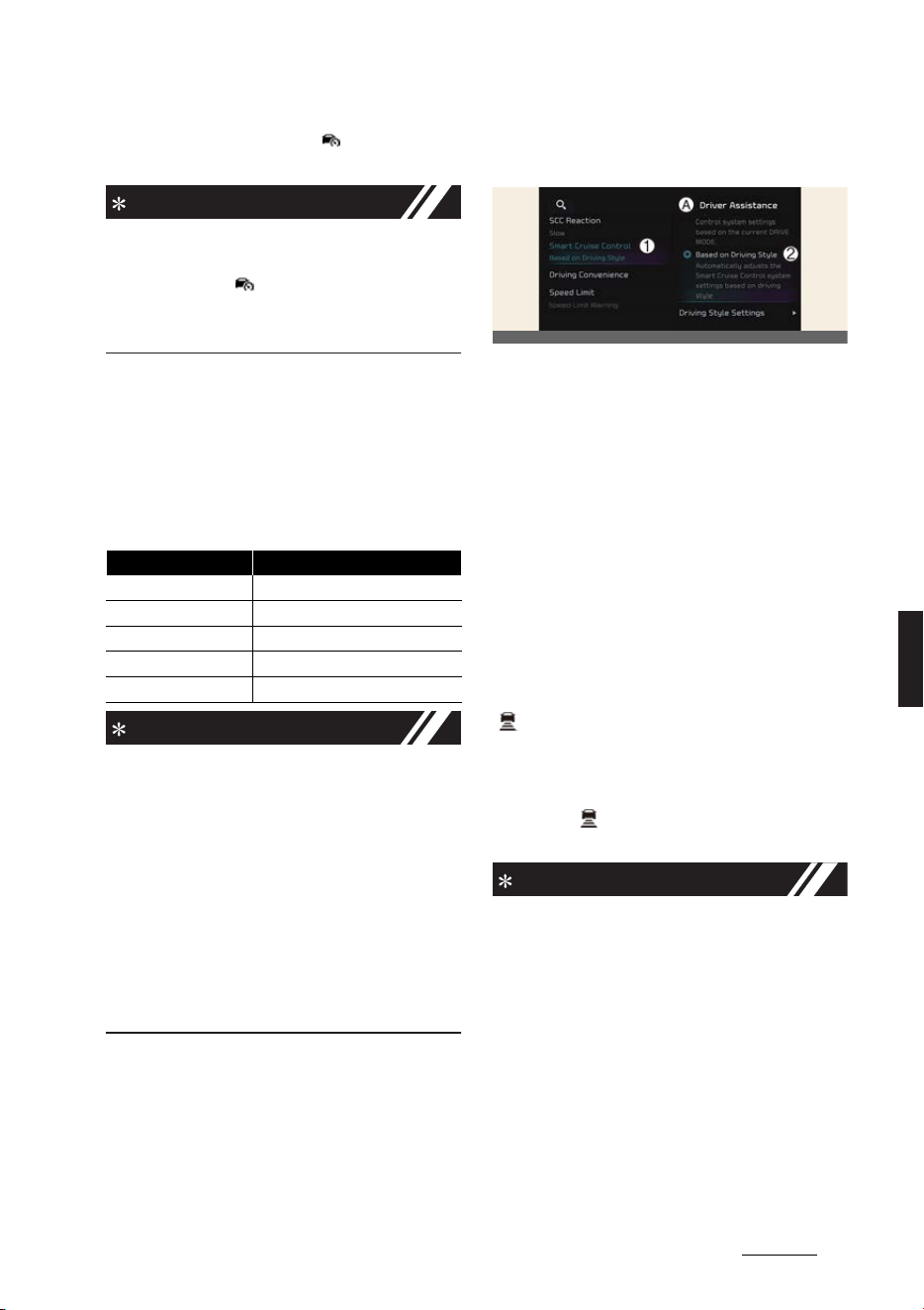
107
6
6
Driving your vehicle Smart Cruise Control (SCC)
Press the Driving Assist ( ) button to
turn Smart Cruise Control off.
NOTICE
If your vehicle is equipped with Manual
Speed Limit Assist, press and hold the
Driving Assist ( ) button to turn off
Smart Cruise Control. However Manual
Speed Limit Assist will turn on.
Based on Driving Mode
Smart Cruise Control will change accel
-
eration based on the drive mode
selected from Drive Mode Integrated
Control function. Refer to the following
chart.
NOTICE
僅 For more details on Drive Mode, refer
to "Drive mode integrated control sys
-
tem" on page 6-35.
僅 Smart Cruise Control may not turn on
or off in some of the drive modes for
the operating conditions are not satis
-
fied.
僅 If your vehicle is not equipped with
Drive Mode Integrated Control sys
-
tem, Smart Cruise Control accelerates
your vehicle at a normal level.
Based on driving style (if
equipped)
A:
Driver assistance
1 SCC (Smart Cruise Control)
2 Based on driving style
With the vehicle on, if
Settings
→
Vehi
-
cle
→
Driver assistance
→
SCC (Smart
Cruise Control)
→
Based on driving
style
is selected from the infotainment
system screen, Smart Cruise Control will
operate based on the driver's driving
style, such as vehicle distance, accelera
-
tion, reaction speed.
While Smart Cruise Control is operating
with
Based on driving mode
selected, if
you press and hold the Vehicle Distance
( ) button, Smart Cruise Control will
change to
Based on driving style
. While
Smart Cruise Control is operating with
Based on driving style
, if the Vehicle
Distance ( ) button is pressed, it will
change to
Based on driving mode
.
NOTICE
僅 If equipped with Based on Driving
Style,
Based on driving mode
and
Based on driving style
can be
selected from the infotainment sys
-
tem screen by selecting
Settings
→
Vehicle
→
Driver assistance
→
SCC
(Smart Cruise Control)
.
僅If
Based on driving mode
is selected,
Smart Cruise Control will operate
based on the drive mode selected.
僅 While Smart Cruise Control is operat
-
ing with
Based on driving style
Drive Mode Smart Cruise Control
SNOW
Normal
ECO
Slow
SPORT
Fast
NORMAL
Normal
GT
Fast
OCV041573L
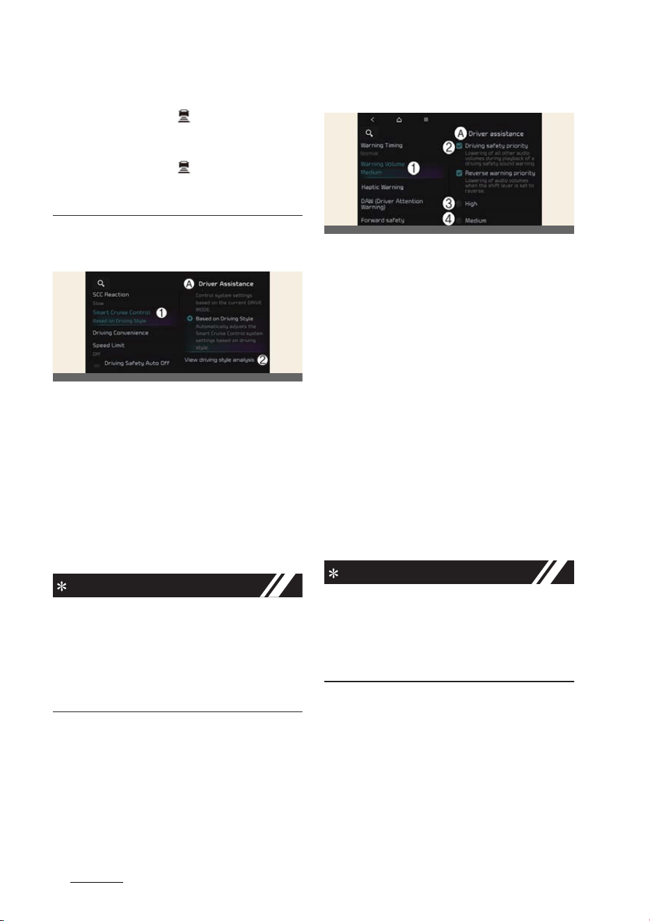
Driving your vehicle
1086
Smart Cruise Control (SCC)
selected, if you press and hold the
Vehicle Distance ( ) button, Smart
Cruise Control will change to Based
on driving mode. Press and hold the
Vehicle Distance ( ) button to
change Smart Cruise Control to
Based on driving style
mode.
View driving style analysis (if
equipped)
A:
Driver assistance
1 SCC (Smart Cruise Control)
2 View driving style analysis
With the vehicle on, select
Settings
→
Vehicle
→
Driver assistance
→
SCC
(Smart Cruise Control)
→
View driving
style analysis
from the infotainment
system screen to check the driver's driv
-
ing style, and to change each driving
style manually.
NOTICE
僅
View driving style analysis
is dis
-
played when
Based on Driving Style
is selected.
僅 Smart Cruise Control learns the
driver's driving styles only when the
driver drives the vehicle.
Warning volume
A:
Driver assistance
1 Warning volume
2 Driving safety priority
3 High
4 Medium
5 Low
6 Off
With the vehicle on,
Settings
→
Vehicle
→
Driver assistance
→
Driving safety
→
Warning volume
on the infotainment
system to change the Warning volume
to adjust the Warning volume levels;
High
,
Medium
,
Low
or
Off
.
If
Driving safety priority
is selected, the
audio volume will temporarily decrease
to warn the driver with the audible warn
-
ing for safe driving.
NOTICE
僅 If the vehicle is restarted, Warning
Volume will maintain the last setting.
僅 If you change the Warning Volume,
the Warning Volume of other Driver
Assistance systems may change.
Smart Cruise Control operation
Operating conditions
Smart Cruise Control will operate when
the following conditions are satisfied.
Basic function
僅 The gear is in D (Drive)
OCV041585L
OCVGT042562L
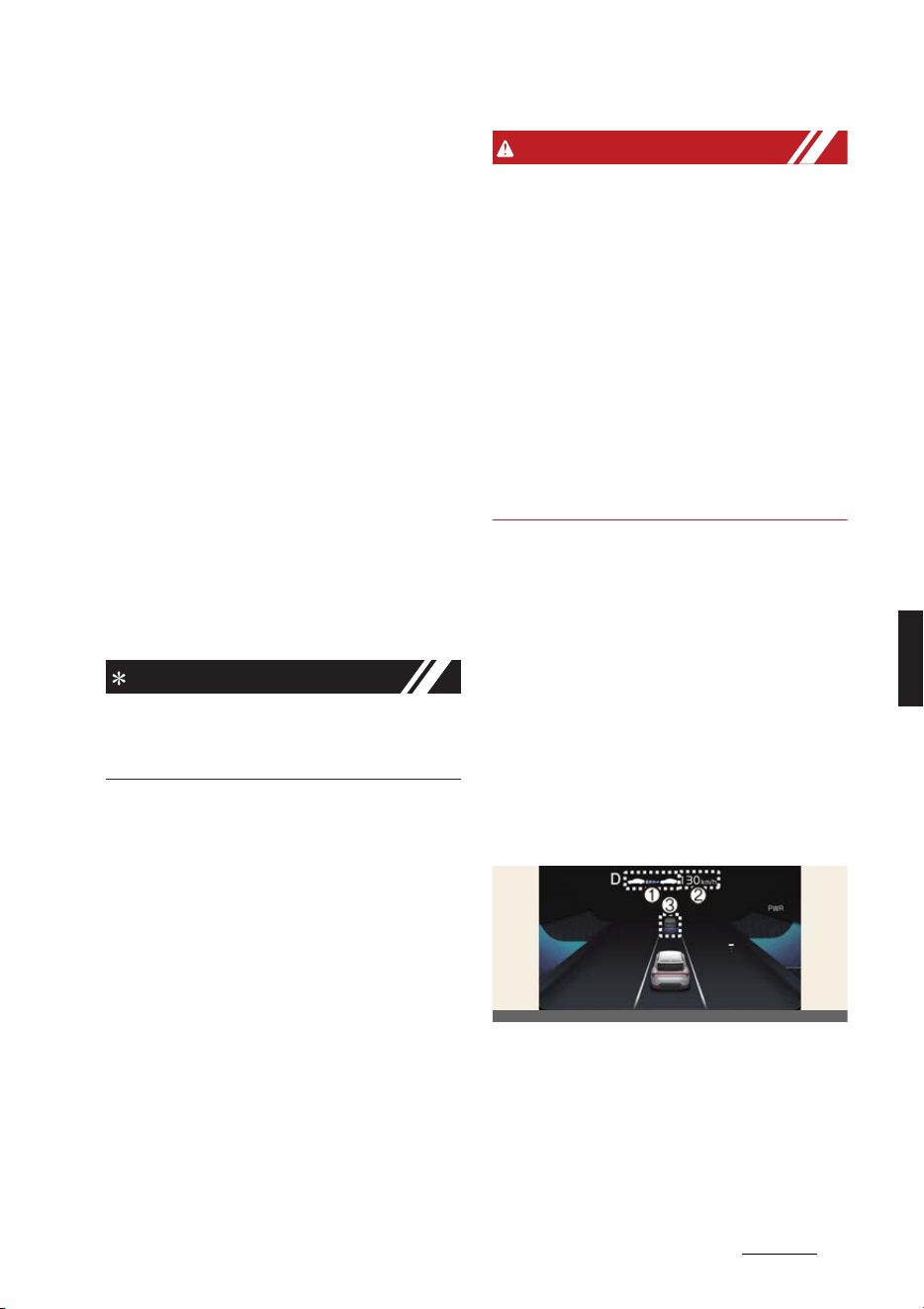
109
6
6
Driving your vehicle Smart Cruise Control (SCC)
僅 The driver's door is closed
僅 EPB (Electronic Parking Brake) is not
applied
僅 Your vehicle speed is within the oper
-
ating speed range
- When there is no vehicle in front:
10~180 km/h (5~110 mph)
- when there is a vehicle in front:
0~180 km/h (0~110 mph)
僅 ESC (Electronic Stability Control) or
ABS is on
僅 ESC (Electronic Stability Control) or
ABS is not controlling the vehicle
僅 Forward Collision-Avoidance Assist
brake control is not operating
僅 Remote Smart Parking Assist brake
control is not operating (if equipped)
僅 The vehicle is not in a power down
status (Power down indicator light is
not illuminated)
NOTICE
When stopped behind another vehicle,
the driver can turn on Smart Cruise Con
-
trol while the brake pedal is depressed.
Overtaking Acceleration Assist
Overtaking Acceleration Assist will oper
-
ate when the turn signal indicator is
turned on to the left (left-hand drive) or
turned on to the right (right-hand drive)
while Smart Cruise Control is operating,
and the following conditions are satis
-
fied:
僅 Your vehicle speed is above 60 km/h
(40 mph)
僅 The hazard warning flasher is off
僅 A vehicle is detected in front of your
vehicle
僅 Deceleration is not needed to main
-
tain distance with the vehicle in front
WARNING
僅 When the turn signal indicator is
turned on to the left (left-hand drive)
or turned on to the right (right-hand
drive) while there is a vehicle ahead,
the vehicle may accelerate temporar
-
ily. Pay attention to the road condi
-
tions at all times.
僅 Regardless of your country's driving
direction, Overtaking Acceleration
Assist will operate when the condi
-
tions are satisfied. When using the
function in countries with different
driving direction, always check the
road conditions at all times.
Smart Cruise Control display and
control
Basic function
You can see the status of the Smart
Cruise Control operation in the Driving
Assist mode on the cluster. Refer to
"Instrument cluster" on page 5-45.
Smart Cruise Control will be displayed as
below depending on the status of the
function.
僅When operating
1. Whether there is a vehicle ahead
and the selected distance level are
displayed.
2. Set speed is displayed.
3. Whether there is a vehicle ahead
and the selected target distance are
displayed.
OCV041187K
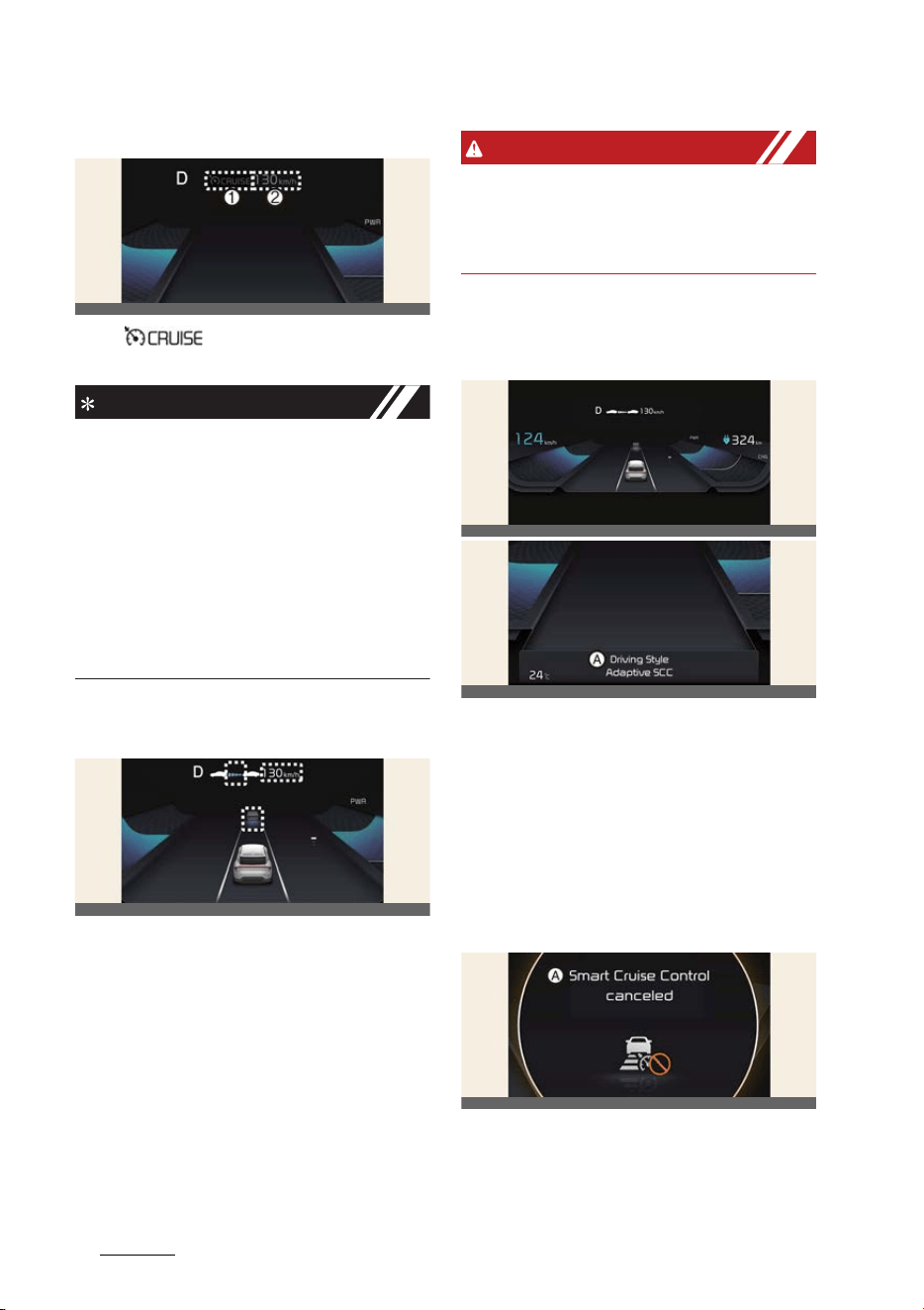
Driving your vehicle
1106
Smart Cruise Control (SCC)
僅 When temporarily canceled
1. ( ) indicator is displayed.
2. The previous set speed is shaded.
NOTICE
僅 The distance of the front vehicle on
the cluster is displayed according to
the actual distance between your
vehicle and the vehicle ahead.
僅 The target distance may vary accord
-
ing to the vehicle speed and the set
distance level. If vehicle speed is low,
even though the vehicle distance have
changed, the change of the target
vehicle distance may be small.
To temporarily accelerate
If you want to speed up temporarily
without altering the set speed while
Smart Cruise Control is operating,
depress the accelerator pedal. While the
accelerator pedal is depressed, the set
speed, distance level and target distance
will blink on the cluster.
However, if the accelerator pedal is
depressed insufficiently, the vehicle may
decelerate.
WARNING
Be careful when accelerating temporar
-
ily, because the speed and distance is
not controlled automatically even if
there is a vehicle in front of you.
Based on Driving Style operating
(if equipped)
A:
Driving Style Adaptive SCC
When Based on Driving Style is operat
-
ing, the message will appear on the clus
-
ter for 2 seconds, and the distance level
and target distance will be displayed
based on the driving style.
Smart Cruise Control temporarily
canceled
A:
Smart Cruise Control canceled
Smart Cruise Control will be temporarily
canceled automatically when:
OCV041188K
OCV041189K
OCV051164L
OCV051165L
OCV051166L
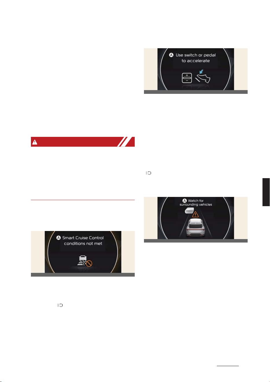
111
6
6
Driving your vehicle Smart Cruise Control (SCC)
僅 The vehicle speed is above 190 km/h
(120 mph)
僅 The vehicle is stopped for a certain
period of time
僅 The accelerator pedal is continuously
depressed for a certain period of time
僅 The conditions for the Smart Cruise
Control to operate is not satisfied
If Smart Cruise Control is temporarily
canceled automatically, a warning mes
-
sage will appear on the cluster, and an
audible warning will sound to warn the
driver.
WARNING
When Smart Cruise Control is temporar
-
ily canceled, distance with the front vehi
-
cle will not be maintained. Always have
your eyes on the road while driving, and
if necessary, depress the brake pedal to
reduce your driving speed in order to
maintain a safe distance.
Smart Cruise Control conditions
not satisfied
A:
Smart Cruise Control conditions not
met
If the Driving Assist button, + switch, -
switch or ( ) switch is operated when
Smart Cruise Control's operating condi
-
tions are not satisfied, a warning mes
-
sage will appear on the cluster, and an
audible warning will sound.
In traffic situation
A:
Use switch or pedal to accelerate
In traffic, your vehicle will stop if the
vehicle ahead of you stops. Also, if the
vehicle ahead of you starts moving, your
vehicle will start as well.
In addition, after the vehicle has stopped
and a certain time have passed, a warn
-
ing message like above will appear on
the cluster. Depress the accelerator
pedal or operate the + switch, - switch or
( ) switch to start driving.
Warning road conditions ahead
A:
Watch for surrounding vehicles
In the following situation, the warning
message will appear on the cluster, and
an audible warning will sound to warn
the driver of road conditions ahead.
僅 The vehicle in front disappears when
Smart Cruise Control is maintaining
the distance with the vehicle ahead
while driving below a certain speed.
僅 While the
Use switch or pedal to
accelerate
message is displayed on
the cluster, if there is no vehicle in
front or the vehicle is far away from
you, and the + switch, – switch or
switch is pushed.
OCV051167L
OCV051168L
OCV051169L
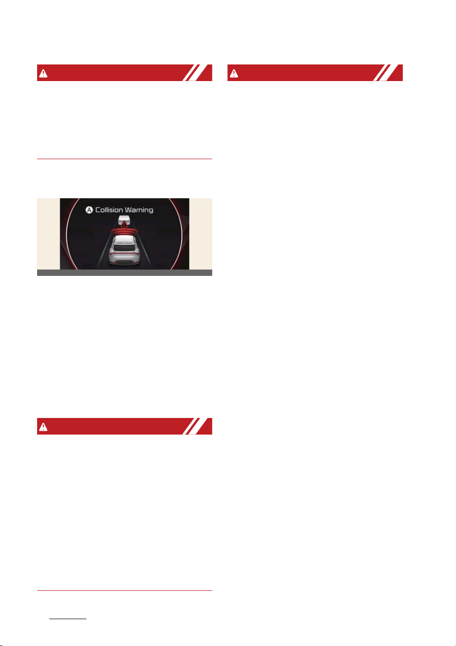
Driving your vehicle
1126
Smart Cruise Control (SCC)
WARNING
Always pay attention to vehicles or
objects that may suddenly appear in
front of you, and if necessary, depress
the brake pedal to reduce your driving
speed in order to maintain a safe dis
-
tance.
Collision warning
A:
Collision Warning
While Smart Cruise Control is operating,
when the collision risk with the vehicle
ahead is high, a warning message will
appear on the cluster, and an audible
warning will sound to warn the driver.
Always have your eyes on the road while
driving, and if necessary, depress the
brake pedal to reduce your driving
speed in order to maintain a safe dis
-
tance.
WARNING
In the following situations, Smart Cruise
Control may not warn the driver of a col
-
lision.
僅 The distance from the front vehicle is
near, and the vehicle speed of the
front vehicle is faster or similar with
your vehicle
僅 The speed of the front vehicle is very
slow or is at a standstill
僅 The accelerator pedal is depressed
right after Smart Cruise Control is
turned on
WARNING
Take the following precautions when
using Smart Cruise Control:
僅 Smart Cruise Control does not substi
-
tute for proper and safe driving. It is
the responsibility of the driver to
always check the speed and distance
to the vehicle ahead.
僅 Smart Cruise Control may not detect
unexpected and sudden situations or
complex driving situations, so always
pay attention to driving conditions
and control your vehicle speed.
僅 Keep Smart Cruise Control off when
the function is not in use to avoid
inadvertently setting a speed.
僅 Do not open the door when Smart
Cruise Control is operating, even if the
vehicle is stopped.
僅 Always be aware of the selected
speed and vehicle to vehicle distance.
僅 Keep a safe distance according to
road conditions and vehicle speed. If
the vehicle to vehicle distance is too
close during high-speed driving, a
serious collision may result. Always
pay attention to the road condition
ahead.
僅 When maintaining distance with the
vehicle ahead, if the front vehicle dis
-
appears, the function may suddenly
accelerate to the set speed. Always be
aware of unexpected and sudden sit
-
uations from occurring.
僅 Vehicle speed may decrease on an
upward sloped road and increase on a
downward sloped road.
僅 Always be aware of situations such as
when a vehicle cuts in suddenly.
僅 When you are towing a trailer or
another vehicle, we recommend that
OCV051116L

113
6
6
Driving your vehicle Smart Cruise Control (SCC)
Smart Cruise Control is turned off due
to safety reasons.
僅 Turn off Smart Cruise Control when
your vehicle is being towed.
僅 Smart Cruise Control may be can
-
celed if interfered by strong electro
-
magnetic waves.
僅 Smart Cruise Control may not detect
an obstacle in front and lead to a colli
-
sion. Always look ahead cautiously to
prevent unexpected and sudden situ
-
ations from occurring.
僅 Vehicles moving in front of you with a
frequent lane change may cause a
delay in the function's reaction or may
cause the function to react to a vehi
-
cle actually in an adjacent lane.
Always drive cautiously to prevent
unexpected and sudden situations
from occurring.
僅 Always be aware of the surroundings
and drive safely, even though a warn
-
ing message does not appear or an
audible warning does not sound.
僅 If any other function's warning mes
-
sage is displayed or warning sound is
generated, Smart Cruise Control
warning message may not be dis
-
played and warning sound may not
be generated.
僅 You may not hear the warning sound
of Smart Cruise Control if the sur
-
rounding is noisy. Always pay atten
-
tion to the road condition ahead.
僅 The vehicle manufacturer is not
responsible for any traffic violation or
accidents caused by the driver while
Smart Cruise Control is operating.
僅 Always set the vehicle speed under
the speed limit in your country.
僅 Vehicle distance, acceleration and
reaction speed may change if the
driver's driving style changes. Always
pay attention to the road condition
ahead.
CAUTION
僅 The vehicle must be driven suffi
-
ciently to reflect the actual driving
style of the driver, such as vehicle dis
-
tance, acceleration and reaction
speed.
僅 Based on Driving Style may not reflect
the driver's driving style or driving
conditions that affects driving safety.
僅 If you are driving in special conditions,
such as snow, rain, fog or steep
sloped roads, the vehicle may not be
driven according to the driver's driv
-
ing style.
NOTICE
僅 Smart Cruise Control may not operate
for 15 seconds after the vehicle is
restarted or the front view camera or
front radar is initialized.
僅 You may hear a sound when the
brake is controlled by Smart Cruise
Control.
僅 Based on Driving Style may not reflect
the driver's driving style that is not
safe such as rapid acceleration.
僅 Based on Driving Style does not
reflect any other driving style other
than vehicle distance, acceleration
and reaction speed.
僅 The paddle shifter does not operate
when Smart Cruise Control is acti
-
vated.
NOTICE
The images or colors may be displayed
differently depending on the specifica
-
tions of the instrument cluster or theme.

Driving your vehicle
1146
Smart Cruise Control (SCC)
Smart Cruise Control malfunc
-
tion and limitations
Smart Cruise Control malfunction
A:
Check Smart Cruise Control System
When Smart Cruise Control is not work
-
ing properly, a warning message will
appear, and the ( ) warning light will
illuminate on the cluster. Have Smart
Cruise Control be inspected by a profes
-
sional workshop. Kia recommends visit
-
ing an authorized Kia dealer/service
partner.
Smart Cruise Control disabled
A:
Smart Cruise Control disabled.
Radar blocked
When the front radar cover or sensor is
covered with snow, rain, or foreign
material, it can reduce the detecting per
-
formance and temporarily limit or dis
-
able Smart Cruise Control.
If this occurs, a warning message will
appear on the cluster.
Smart Cruise Control will operate nor
-
mally when snow, rain or foreign mate
-
rial is removed.
WARNING
Even though the warning message does
not appear on the cluster, Smart Cruise
Control may not properly operate.
CAUTION
Smart Cruise Control may not properly
operate in an area (e.g. open terrain),
where there is nothing to detect after
turning ON the vehicle.
Limitations of Smart Cruise Con
-
trol
Smart Cruise Control may not operate
normally under the following circum
-
stances:
僅 The detecting sensor or the surround
-
ings are contaminated or damaged
僅Washer fluid is continuously sprayed,
or the wiper is on
僅 The camera lens is contaminated due
to tinted, filmed or coated windshield,
damaged glass, or stuck of foreign
material (sticker, bug, etc.) on the
glass
僅 Moisture is not removed or frozen on
the windshield
僅 The field of view of the front view
camera is obstructed by sun glare
僅 Street light or light from an oncoming
vehicle is reflected on the wet road
surface, such as a puddle on the road
僅 The temperature around the front
view camera is high or low
僅 An object is placed on the dashboard
僅 The surrounding is very bright
僅 The surrounding is very dark, such as
in a tunnel, etc.
僅 The brightness changes suddenly, for
example when entering or exiting a
tunnel
OCV051170L
OCV051171L

115
6
6
Driving your vehicle Smart Cruise Control (SCC)
僅 The brightness outside is low, and the
headlamps are not on or are not
bright
僅 Driving in heavy rain or snow, or thick
fog
僅 Driving through steam, smoke or
shadow
僅Only part of the vehicle is detected
僅 The vehicle in front has no tail lights,
tail lights are located unusually, etc.
僅 The brightness outside is low, and the
tail lamps of the vehicle in front are
not on or are not bright
僅 The rear of the front vehicle is small or
does not look normal (i.e. tilted, over
-
turned, etc.)
僅 The front vehicle's ground clearance
is low or high
僅 A vehicle suddenly cuts in front
僅 Your vehicle is being towed
僅 Driving through a tunnel or iron
bridge
僅 Driving near areas containing metal
substances, such as a construction
zone, railroad, etc.
僅 A material is near that reflects very
well on the front radar, such as a
guardrail, nearby vehicle, etc.
僅 The bumper around the front radar is
impacted, damaged or the front radar
is out of position
僅 The temperature around the front
radar is high or low
僅 Driving in large areas where there are
few vehicles or structures (i.e. desert,
meadow, suburb, etc.)
僅 The vehicle in front is made of mate
-
rial that does not reflect on the front
radar
僅 Driving near a highway (or motorway)
interchange or tollgate
僅 Driving on a slippery surface due to
snow, water puddle, ice, etc.
僅 Driving on a curved road
僅 The vehicle in front is detected late
僅 The vehicle in front is suddenly
blocked by a obstacle
僅 The vehicle in front suddenly changes
lane or suddenly reduces speed
僅 The vehicle in front is bent out of
shape
僅 The front vehicle's speed is fast or
slow
僅 With a vehicle in front, your vehicle
changes lane suddenly at low speed
僅 The vehicle in front is covered with
snow
僅 Unstable driving
僅 You are on a roundabout and the
vehicle in front is not detected
僅 You are continuously driving in a cir
-
cle
僅 Driving in a parking lot
僅 Driving through a construction area,
unpaved road, partial paved road,
uneven road, speed bumps, etc.
僅 Driving on an incline road, curved
road, etc.
僅 Driving through a roadside with trees
or streetlights
僅 The adverse road conditions cause
excessive vehicle vibrations while
driving
僅 Your vehicle height is low or high due
to heavy loads, abnormal tire pres
-
sure, etc.
僅 Driving through a narrow road where
trees or grass are overgrown
僅 There is interference by electromag
-
netic waves, such as driving in an area
with strong radio waves or electrical
noise
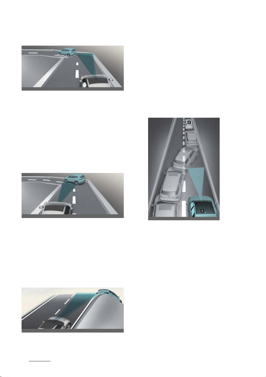
Driving your vehicle
1166
Smart Cruise Control (SCC)
僅 Driving on a curved road
On curved roads, Smart Cruise Con
-
trol may not detect a vehicle in the
same lane, and may accelerate to the
set speed. Also, vehicle speed may
rapidly decrease when the vehicle
ahead is detected suddenly.
Select the appropriate set speed on
curved roads and apply the brake
pedal or accelerator pedal according
to the road and driving conditions
ahead.
Your vehicle speed can be reduced
due to a vehicle in the adjacent lane.
Check to be sure that the road condi
-
tions permit safe operation of the
Smart Cruise Control and if necessary,
depress the brake pedal to reduce
your driving speed in order to main
-
tain a safe distance.
僅 Driving on an inclined road
During uphill or downhill driving, the
Smart Cruise Control may not detect a
moving vehicle in your lane, and
cause your vehicle to accelerate to the
set speed. Also, vehicle speed will rap
-
idly decrease when the vehicle ahead
is detected suddenly.
Select the appropriate set speed on
sloped roads and apply the brake
pedal or accelerator pedal according
to the road and driving conditions
ahead.
僅 Changing lanes
[A]: Your vehicle
[B]: Lane changing vehicle
When a vehicle moves into your lane
from an adjacent lane, it cannot be
detected by the sensor until it is in the
sensor's detection range. Smart
Cruise Control may not immediately
detect the vehicle when the vehicle
changes lanes abruptly. Always pay
attention to the road and driving con
-
ditions and drive safely. If necessary,
depress the brake pedal to reduce
your driving speed in order to main
-
tain a safe distance.
OCV051061L
OCV051062L
OCV051063L
OCV051238L
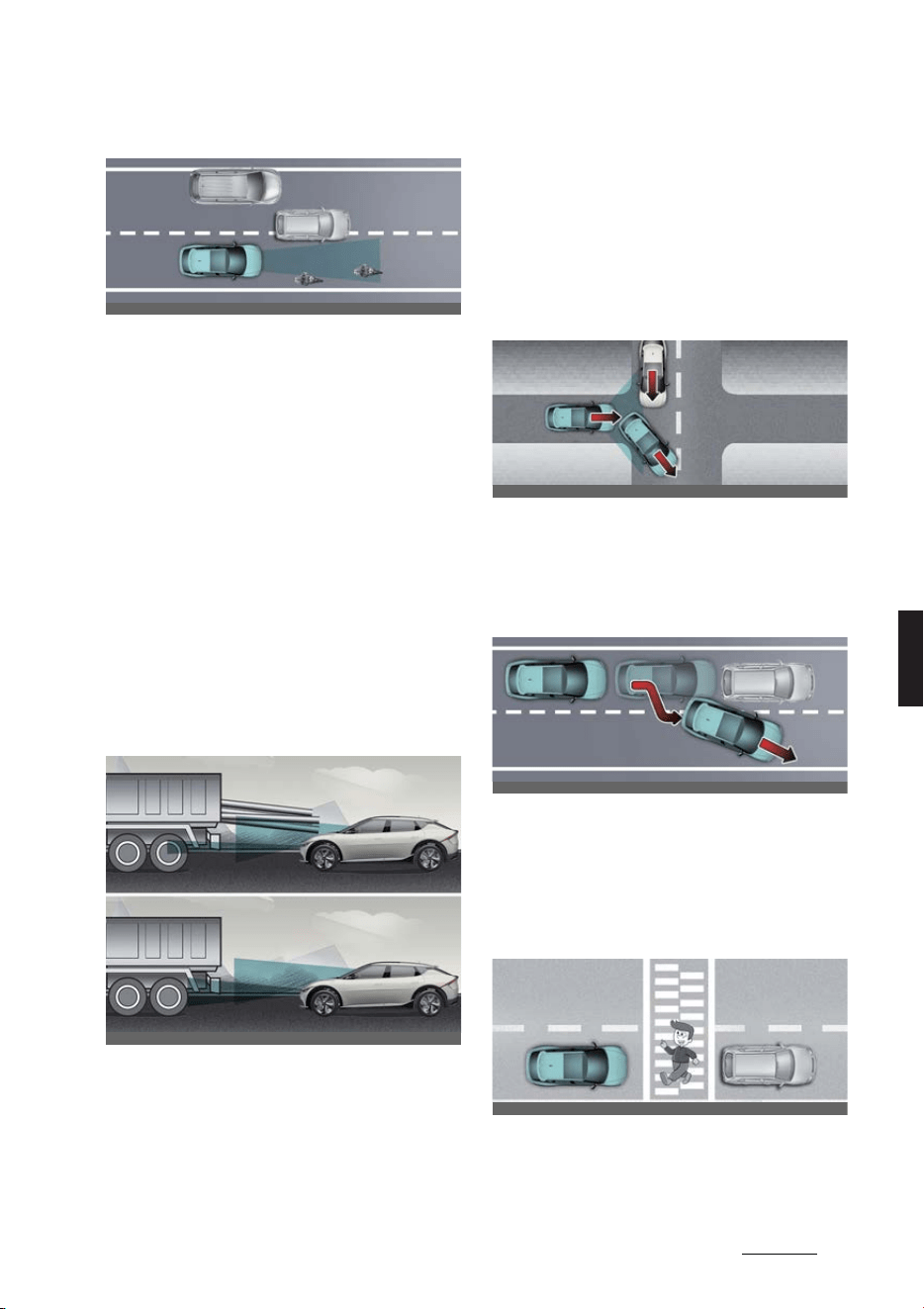
117
6
6
Driving your vehicle Smart Cruise Control (SCC)
僅 Detecting a vehicle
In the following cases, some vehicles
in your lane cannot be detected by
the sensor:
- Vehicles offset to one side
- Slow-moving vehicles or sudden-
decelerating vehicles
- Vehicles that has the front lifted
due to heavy loads
-Oncoming vehicles
- Stopped vehicles
- Vehicles with small rear profile,
such as trailers
- Narrow vehicles, such as motorcy
-
cles or bicycles
-Special vehicles
- Animals and pedestrians
In the following cases, the vehicle in
front cannot be detected by the sen
-
sor. Always pay attention to the road
and driving conditions and drive
safely. If necessary, adjust your vehi
-
cle speed.
- Vehicles with higher ground clear
-
ance or vehicles carrying loads that
stick out of the back of the vehicle
- Vehicles that has the front lifted
due to heavy loads
- You are steering your vehicle
- Driving on narrow or sharply
curved roads
僅 When a vehicle ahead disappears at
an intersection, your vehicle may
accelerate.
Always pay attention to road and driv
-
ing conditions while driving.
僅 When a vehicle in front of you merges
out of the lane, Smart Cruise Control
may not immediately detect the new
vehicle that is now in front of you.
Always pay attention to road and driv
-
ing conditions while driving.
僅 Always look out for pedestrians when
your vehicle is maintaining a distance
with the vehicle ahead.
OCV051010L
OCV051032L_2
OCV051064L
OCV051065L
OCV051066L
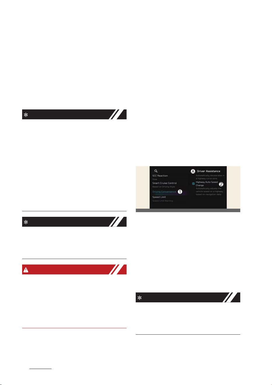
Driving your vehicle
1186
Navigation-based Smart Cruise Control (NSCC)
Navigation-based Smart
Cruise Control (NSCC) (if
equipped)
Navigation-based Smart Cruise Control
will help automatically adjust vehicle
speed when driving on highways (or
motorways) by using road information
from the navigation function while Smart
Cruise Control is operating.
NOTICE
僅 Navigation-based Smart Cruise Con
-
trol is available only on controlled
access road of certain highways.
* Controlled access road indicates
roads with limited entrances and
exits that allow uninterrupted high
speed traffic flow. Only passenger
cars and motorcycles are allowed on
controlled access roads.
僅 Additional highways may be
expanded by future navigation
updates.
NOTICE
Navigation-based Smart Cruise Control
operates on main roads of highways (or
motorways), and does not operate on
interchanges or junctions.
WARNING
Navigation-based Smart Cruise Control
is a supplemental function and is not a
substitute for safe driving. It is the
responsibility of the driver to always
check the speed and distance to the
vehicle ahead. Always drive safely and
use caution.
Highway Curve Zone Auto Slow
-
down
If vehicle speed is high, Highway Curve
Zone Auto Slowdown function will tem
-
porarily decelerate your vehicle or limit
acceleration to help you drive safely on a
curve based on the curve information
from the navigation.
Highway Set Speed Auto Change
Highway Set Speed Auto Change func
-
tion automatically changes Smart Cruise
Control set speed based on the speed
limit information from the navigation.
Navigation-based Smart Cruise
Control settings
A:
Driver assistance
1 Driving convenience
2 Highway Auto Speed Change
With the vehicle on, select
Settings
→
Vehicle
→
Driver assistance
→
Driving
Convenience
→
Highway Auto Speed
Change
from the infotainment system
screen to turn on Navigation-based
Smart Cruise Control and deselect to
turn off the function.
NOTICE
When there is a problem with Naviga
-
tion-based Smart Cruise Control, the
function cannot be set from the Settings
menu.
OCV041575L
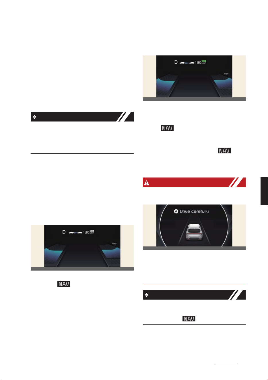
119
6
6
Driving your vehicle Navigation-based Smart Cruise Control (NSCC)
Navigation-based Smart Cruise
Control operation
Operating conditions
Navigation-based Smart Cruise Control
is ready to operate if all of the following
conditions are satisfied:
僅 Smart Cruise Control is operating
僅 Driving on main roads of highways (or
motorways)
NOTICE
For more details on how to operate
Smart Cruise Control, refer to "Smart
Cruise Control (SCC) (if equipped)" on
page 6-104.
Navigation-based Smart Cruise
Control display and control
When Navigation-based Smart Cruise
Control operates, it will be displayed on
the cluster as follows:
Navigation-based Smart Cruise
Control standby
If the operating conditions are satisfied,
the white ( ) symbol will illuminate.
Navigation-based Smart Cruise
Control operating
If temporary deceleration is required in
the standby state and Navigation-based
Smart Cruise Control is operating, the
green ( ) symbol will illuminate on
the cluster.
If the Highway Set Speed Auto Change
function operates, the green ( )
symbol and set speed will illuminate on
the cluster, and an audible warning will
sound.
WARNING
The warning message will appear in the
following circumstances:
A:
Drive carefully
僅 Navigation-based Smart Cruise Con
-
trol is not able to slow down your
vehicle to a safe speed.
NOTICE
Highway Curve Zone Auto Slowdown
and Set Speed Auto Change function
uses the same ( ) symbol.
OCV051172L
OCV051173L
OCV051118L

Driving your vehicle
1206
Navigation-based Smart Cruise Control (NSCC)
Highway Curve Zone Auto Slow
-
down
僅 Depending on the curve ahead on the
highway (or motorway), the vehicle
will decelerate, and after passing the
curve, the vehicle will accelerate to
Smart Cruise Control set speed.
僅 Vehicle deceleration time may differ
depending on the vehicle speed and
the degree of the curve on the road.
The higher the driving speed, deceler
-
ation will start faster.
Highway Set Speed Auto Change
僅 Highway Set Speed Auto Change
function will operate when Smart
Cruise Control set speed and the
highway (or motorway) speed limit is
matched.
僅 While Highway Set Speed Auto
Change function is operating, when
the highway (or motorway), speed
limit changes, Smart Cruise Control
set speed automatically changes to
the changed speed limit.
僅 If Smart Cruise Control set speed is
adjusted different from the speed
limit, Highway Set Speed Auto
Change function will be in the standby
state.
僅 If Highway Set Speed Auto Change
function has changed to the standby
state by driving on a road other than
the highway (or motorway) main road,
Highway Set Speed Auto Change
function will operate again when you
drive on the main road again without
setting the set speed.
僅 If Highway Set Speed Auto Change
function has changed to the standby
state by depressing the brake pedal,
press the ( ) switch to restart the
function.
僅 Highway Set Speed Auto Change
function does not operate on highway
interchanges or junctions.
NOTICE
僅 Highway Set Speed Auto Change
function only operates based on the
speed limits of the highway (or motor
-
way), it does not work with the speed
cameras.
僅 When Highway Set Speed Auto
Change function is operating, the
vehicle automatically accelerates or
decelerates when the highway (or
motorway) speed limit changes.
僅 The maximum set speed for Highway
Set Speed Auto Change function is
140 km/h (90 mph).
僅 If the speed limit of a new road is not
updated in the navigation, Highway
Set Speed Auto Change function may
not operate properly.
僅 If the speed unit is set to a unit other
than the speed unit used in your
country, Highway Set Speed Auto
Change function may not operate
properly.
NOTICE
The images or colors may be displayed
differently depending on the specifica
-
tions of the instrument cluster or theme.
Navigation-based Smart Cruise
Control limitations
Navigation-based Smart Cruise Control
may not operate normally under the fol
-
lowing circumstances:
僅 The navigation is not working prop
-
erly
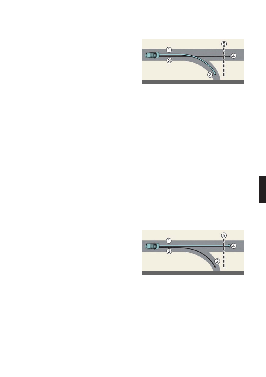
121
6
6
Driving your vehicle Navigation-based Smart Cruise Control (NSCC)
僅 Map information is not transmitted
due to infotainment system's abnor
-
mal operation
僅 Speed limit and road information in
the navigation is not updated
僅 The map information and the actual
road is different because of real-time
GPS data or map information error
僅 The navigation searches for a route
while driving
僅 GPS signals are blocked in areas such
as a tunnel
僅 A road that divides into two or more
roads and joins again
僅 The driver goes off course the route
set in the navigation
僅 The route to the destination is
changed or canceled by resetting the
navigation
僅 The vehicle enters a service station or
rest area
僅 Android Auto or Car Play is operating
僅 The navigation cannot detect the cur
-
rent vehicle position (ex: elevated
roads including overpass adjacent to
general roads or nearby roads exist in
a parallel way)
僅 The navigation is being updated while
driving
僅 The navigation is being restarted
while driving
僅 The speed limit of some sections
changes according to the road situa
-
tions
僅 Driving on a road under construction
僅 Driving on a road that is controlled
僅 There is bad weather, such as heavy
rain, heavy snow, etc.
僅 Driving on a road that is sharply
curved
[1]: Set route, [2]: Branch line, [3]: Driving
route, [4]: Main road, [5]: Curved road
section
僅 When there is a difference between
the navigation set route (branch line)
and the driving route (main road),
Highway Curve Zone Auto Slowdown
function may not operate until the
driving route is recognized as the
main road.
僅 When the vehicle's driving route is
recognized as the main road by main
-
taining the main road instead of the
navigation set route, Highway Curve
Zone Auto Slowdown function will
operate. Depending on the distance to
the curve and the current vehicle
speed, vehicle deceleration may not
be sufficient or may decelerate rap
-
idly.
[1]: Main road, [2]: Branch line, [3]: Driv
-
ing route, [4]: Set route, [5]: Curved road
section
僅 When there is a difference between
the navigation route (main road) and
the driving route (branch line), High
-
way Curve Zone Auto Slowdown func
-
tion will operate temporarily based on
the curve information on the main
road.
OCV051067L
OCV051068L
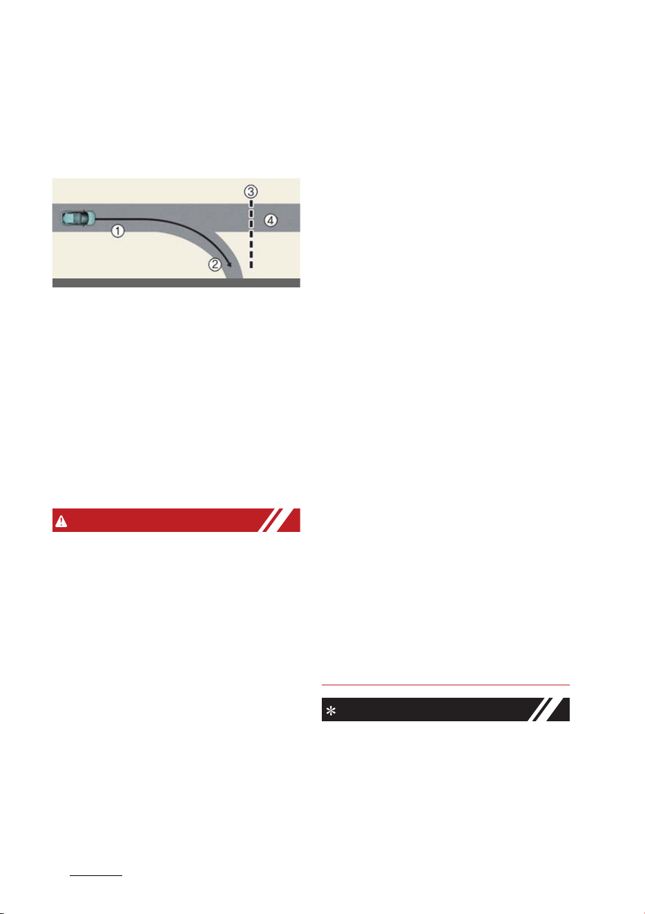
Driving your vehicle
1226
Navigation-based Smart Cruise Control (NSCC)
僅 When it is judged that you are driving
out of the route by entering the high
-
way interchange or junction, Highway
Curve Zone Auto Slowdown function
will not operate.
[1]: Driving route, [2]: Branch line, [3]:
Curved road section, [4]: Main road
僅 If there is no destination set on the
navigation, Highway Curve Zone Auto
Slowdown function will operate based
on the curve information on the main
road.
僅 Even if you depart from the main
road, Highway Curve Zone Auto Slow
-
down function may temporarily oper
-
ate due to navigation information of
the highway curve section.
WARNING
僅 Navigation-based Smart Cruise Con
-
trol is not a substitute for safe driving
practices, but a convenience function.
Always have your eyes on the road,
and it is the responsibility of the driver
to avoid violating traffic laws.
僅 The navigation's speed limit informa
-
tion may differ from the actual speed
limit information on the road. It is the
driver's responsibility to check the
speed limit on the actual driving road
or lane.
僅 Navigation-based Smart Cruise Con
-
trol will automatically be canceled
when you leave the highway (or
motorway) main road. Always pay
attention to road and driving condi
-
tions while driving.
僅 Navigation-based Smart Cruise Con
-
trol may not operate due to the exis
-
tence of leading vehicles and the
driving conditions of the vehicle.
Always pay attention to road and driv
-
ing conditions while driving.
僅 When you are towing a trailer or
another vehicle, we recommend that
Navigation-based Smart Cruise Con
-
trol is turned off due to safety rea
-
sons.
僅 After you pass through a tollgate on a
highway (or motorway), Navigation-
based Smart Cruise Control will oper
-
ate based on the first lane. If you enter
one of the other lanes, the function
might not operate properly.
僅 The vehicle will accelerate if the driver
depresses the accelerator pedal while
Navigation-based Smart Cruise Con
-
trol is operating, and the function will
not decelerate the vehicle. However, if
the accelerator pedal is depressed
insufficiently, the vehicle may deceler
-
ate.
僅 If the driver accelerates and releases
the accelerator pedal while Naviga
-
tion-based Smart Cruise Control is
operating, the vehicle may not decel
-
erate sufficiently or may rapidly
decelerate to a safe speed.
僅 If the curve is too large or too small,
Navigation-based Smart Cruise Con
-
trol may not operate.
NOTICE
僅 The speed information on the cluster
and navigation may differ.
僅 The time gap could occur between
the navigation's guidance and when
Navigation-based Smart Cruise Con
-
trol operation starts and ends.
OCV051069L
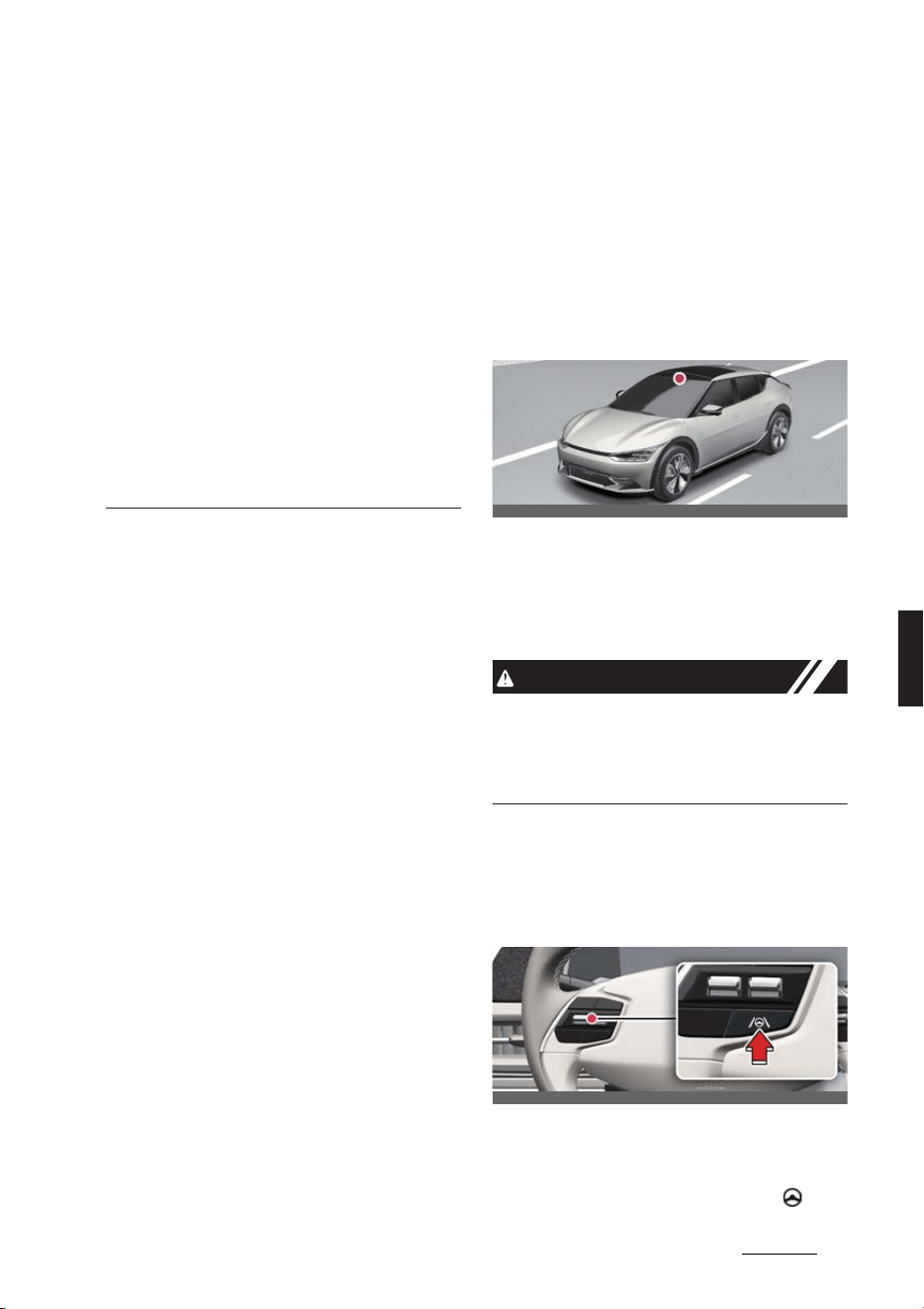
123
6
6
Driving your vehicle Lane Following Assist (LFA)
僅 Even if you are driving at a speed
lower than Smart Cruise Control set
speed, acceleration may be limited by
the curve sections ahead.
僅 If Navigation-based Smart Cruise
Control is operating while leaving the
main road to enter an interchange,
junction, rest area, etc., the function
may operate for a certain period of
time.
僅 Deceleration by Navigation-based
Smart Cruise Control may feel it is not
sufficient due to road conditions such
as uneven road surfaces, narrow
lanes, etc.
Lane Following Assist (LFA)
Lane Following Assist is designed to help
detect lane markings and/or vehicles on
the road, and assists the driver's steering
to help keep the vehicle between lanes.
Detecting sensor
Front view camera
The front view camera is used as a
detecting sensor to detect lane markings
and front vehicles.
Refer to the picture above for the
detailed location of the detecting sensor.
CAUTION
For more details on the precautions of
the front view camera, refer to "Forward
Collision-Avoidance Assist (FCA) (if
equipped)" on page 6-43.
Lane Following Assist settings
Turning Lane Following Assist
On/Off
With the vehicle on, shortly press the
Lane Driving Assist button located on
the steering wheel to turn on Lane Fol
-
lowing Assist. The gray or green ( )
OCV051017L
OCV051033L
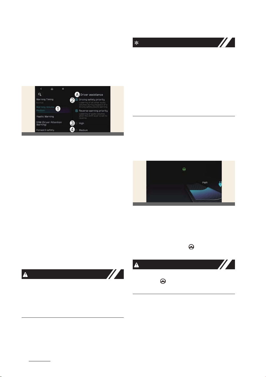
Driving your vehicle
1246
Lane Following Assist (LFA)
indicator light will illuminate on the clus
-
ter.
Press the button again to turn off the
function.
Warning volume
A:
Driver assistance
1 Warning volume
2 Driving safety priority
3 High
4 Medium
5 Low
6 Off
With the vehicle on, touch
Settings
→
Vehicle
→
Driver assistance
→
Driving
safety
→
Warning volume
on the info
-
tainment system to change the Warning
volume to adjust the Warning volume
levels;
High
,
Medium
,
Low
or
Off
.
If
Driving safety priority
is selected, the
audio volume will temporarily decrease
to warn the driver with the audible warn
-
ing for safe driving.
CAUTION
When the trailer is connected, Lane Fol
-
lowing Assist automatically turns off (if
equipped). In this case, you cannot get
help from Lane Following Assist. Always
drive with care.
NOTICE
僅 When the vehicle is restarted, Lane
Following Assist settings will retain its
settings.
僅 If you change the Warning Volume,
the Warning Volume of other Driver
Assistance systems may change.
僅If '
Off
' is selected, the Hands-off
Warning Volume will not turn off, but
the volume will sound as '
Low
'.
Lane Following Assist operation
Warning and control
Lane Following Assist
If the vehicle ahead and/or both lane
markings are detected and your vehicle
speed is below 180 km/h (110 mph),
Lane Following Assist will help center the
vehicle in the lane by assisting the steer
-
ing wheel. The green ( ) indicator light
will illuminate on the cluster.
CAUTION
When the steering wheel is not assisted,
the green ( ) indicator light will blink
and change to grey.
OCVGT042562L
OCV051174L
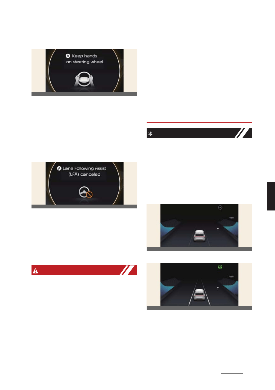
125
6
6
Driving your vehicle Lane Following Assist (LFA)
Hands-off warning
A:
Keep hands on steering wheel
If the driver takes their hands off the
steering wheel for several seconds, the
warning message will appear and an
audible warning will sound in stages.
僅First stage: Warning message
僅 Second stage: Warning message (red
steering wheel) and audible warning
A:
Lane Following Assist (LFA) can
-
celed
If the driver still does not have their
hands on the steering wheel after the
hands-off warning, the warning mes
-
sage will appear and Lane Following
Assist will be automatically canceled.
WARNING
僅 The steering wheel may not be
assisted if the steering wheel is held
very tight or the steering wheel is
steered over a certain degree.
僅Lane Following Assist does not oper
-
ate at all times. It is the responsibility
of the driver to safely steer the vehicle
and to maintain the vehicle in its lane.
僅 The hands–off warning message may
appear late depending on road condi
-
tions. Always have your hands on the
steering wheel while driving.
僅 If the steering wheel is held very
lightly the hands–off warning mes
-
sage may appear because Lane Fol
-
lowing Assist may not detect that the
driver has their hands on the steering
wheel.
僅 If you attach objects to the steering
wheel, the hands-off warning may not
work properly.
NOTICE
僅 For more details on setting Lane Fol
-
lowing Assist in the infotainment sys
-
tem, refer to Navigation Quick
Reference Guide.
僅 When both lane markings are
detected, the lane lines on the cluster
will change from grey to white.
Lane undetected
Lane detected
僅 The images and colors in the cluster
may differ depending on the cluster
type or theme selected from the clus
-
ter.
僅 If lane markings are not detected,
steering wheel control by Lane Fol
-
OCV051133L
OCV051175L
OCV041159K
OCV041160L
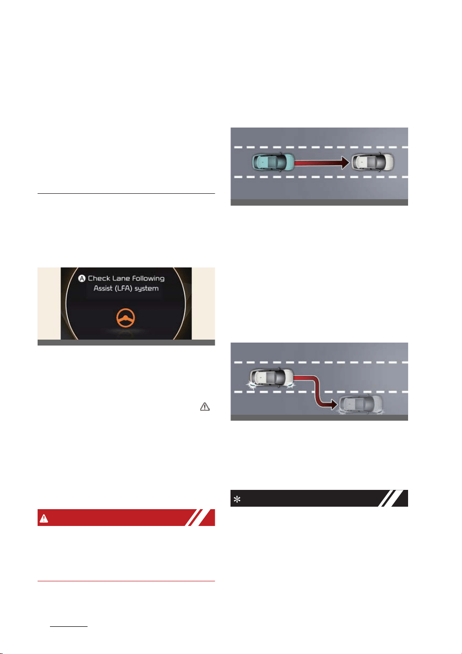
Driving your vehicle
1266
Highway Driving Assist (HDA)
lowing Assist can be limited depend
-
ing on whether a vehicle is in front or
the driving conditions of the vehicle.
僅 Even though the steering is assisted
by Lane Following Assist, the driver
may control the steering wheel.
僅 The steering wheel may feel heavier
or lighter when the steering wheel is
assisted by Lane Following Assist than
when it is not.
Lane Following Assist malfunc
-
tion and limitations
Lane Following Assist malfunc
-
tion
A:
Check Lane Following Assist (LFA)
system
When Lane Following Assist is not work
-
ing properly, the warning message will
appear and the master warning light ( )
will illuminate on the cluster. If this
occurs, have Lane Following Assist be
inspected by a professional workshop.
Kia recommends visiting an authorized
Kia dealer/service partner.
Limitations of Lane Following
Assist
WARNING
For more details on Lane Following
Assist precautions, refer to "Lane Keep
-
ing Assist (LKA) (if equipped)" on page 6-
62.
Highway Driving Assist (HDA)
(if equipped)
Basic function
Highway Driving Assist is designed to
help detect vehicles and lanes ahead,
and help maintain distance from the
vehicle ahead, maintain the set speed,
and keep the vehicle between lanes
while driving on the highway (or motor
-
way).
Highway Lane Change Assist (if
equipped)
Highway Lane Change Assist function
helps change lanes to the direction the
driver slightly moves the turn signal
switch if the function judges that lane
change is possible.
NOTICE
僅 Highway Driving Assist is available
only on controlled access road of cer
-
tain highways. (except for the inter
-
change/junction)
* Controlled access road indicates
roads with limited entrances and
exits that allow uninterrupted high
OCV051176L
OCV051070L
OCV051071L
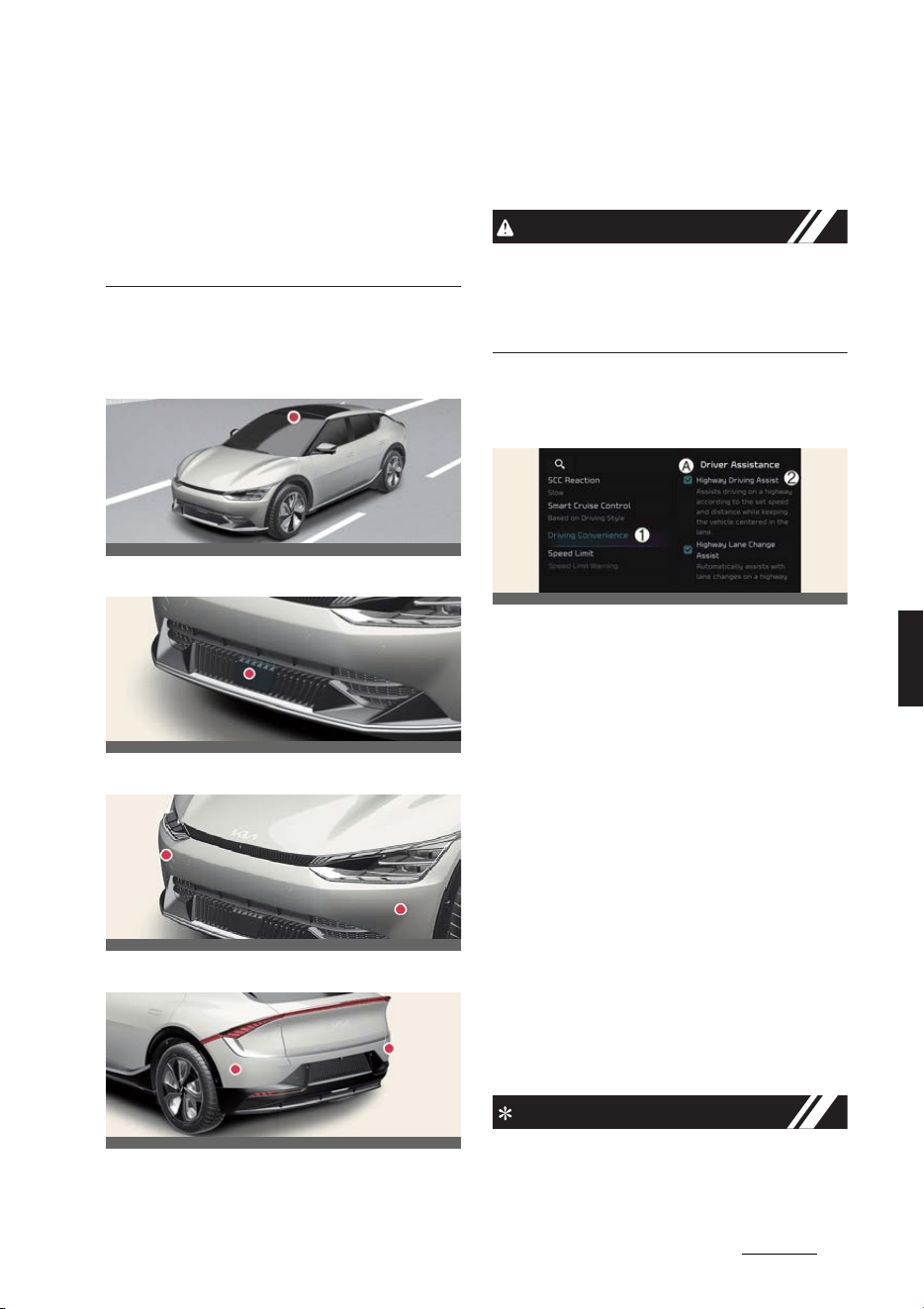
127
6
6
Driving your vehicle Highway Driving Assist (HDA)
speed traffic flow. Only passenger
cars and motorcycles are allowed on
controlled access roads.
僅 Additional highways may be
expanded by future navigation
updates.
Detecting sensor
Front view camera
Front radar
Front corner radar (if equipped)
Rear corner radar (if equipped)
Refer to the picture above for the
detailed location of the detecting sen
-
sors.
CAUTION
For more details on the precautions of
the detecting sensors, refer to "Forward
Collision-Avoidance Assist (FCA) (if
equipped)" on page 6-43.
Highway Driving Assist settings
Basic function
A:
Driver assistance
1 Driving convenience
2 HDA (Motorway Driving Assist)
With the vehicle on, select or deselect
Settings
→
Vehicle
→
Driver assis
-
tance
→
Driving Convenience
from the
infotainment system screen to set
whether or not to use each function.
僅If
"HDA (Motorway Driving Assist)
is
selected, it helps maintain distance
from the vehicle ahead, maintain the
set speed, and helps center the vehi
-
cle in the lane.
Highway Lane Change Assist (if
equipped)
If
Lane change assist (motorway)
is
selected, it helps the driver change
lanes.
NOTICE
僅When
"HDA (Motorway Driving
Assist)
is deselected, the setting for
OCV051017L
OCV051005L
OCV051024L
OCV051025L
OCV041576L
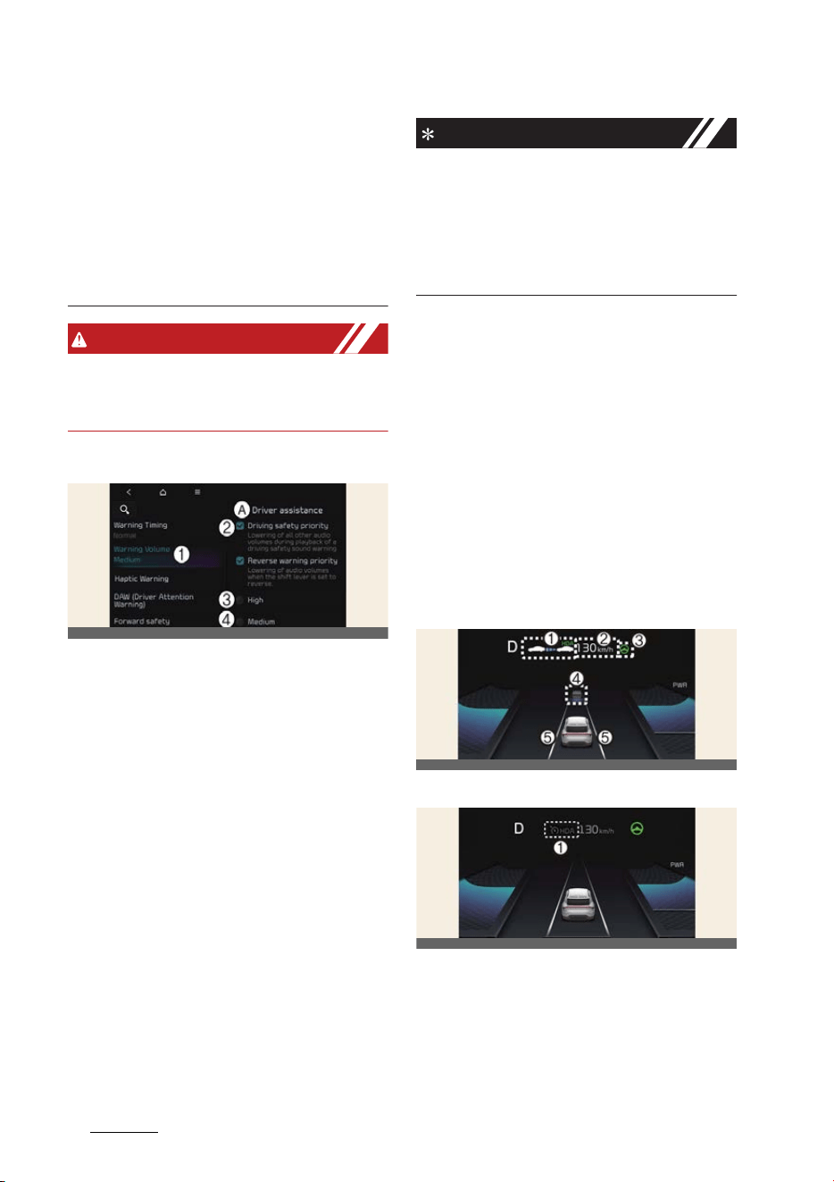
Driving your vehicle
1286
Highway Driving Assist (HDA)
Lane change assist (motorway)
can
-
not be changed.
僅 If there is a problem with the func
-
tions, the settings cannot be changed.
Have the function be inspected by an
authorized Kia dealer/service partner.
僅 If the vehicle is restarted, the func
-
tions will maintain the last setting.
WARNING
For your safety, change the Settings
after parking the vehicle at a safe loca
-
tion.
Warning volume
A:
Driver assistance
1 Warning volume
2 Driving safety priority
3 High
4 Medium
5 Low
6 Off
With the vehicle on, touch
Settings
→
Vehicle
→
Driver assistance
→
Driving
safety
→
Warning volume
on the info
-
tainment system to change the Warning
volume to adjust the Warning volume
levels;
High
,
Medium
,
Low
or
Off
.
If
Driving safety priority
is selected, the
audio volume will temporarily decrease
to warn the driver with the audible warn
-
ing for safe driving.
NOTICE
僅 If Off is selected, the Hands-off Warn
-
ing Volume will not turn off, but the
volume will sound as Low.
僅 If you change the Warning volume,
the Warning volume of other Driver
Assistance systems may change.
Highway Driving Assist operation
Basic function
Highway Driving Assist display
and control
You can see the status of the Highway
Driving Assist operation in the Driving
Assist view on the cluster. Refer to "LCD
display" on page 5-47.
Highway Driving Assist will be displayed
as below depending on the status of the
function.
Operating State
Standby State
1
Highway Driving Assist indicator,
whether there is a vehicle ahead and
the selected distance level are dis
-
played.
僅 Highway Driving Assist indicator
- Green: Operating state
OCVGT042562L
OCV041202K
OCV051253L
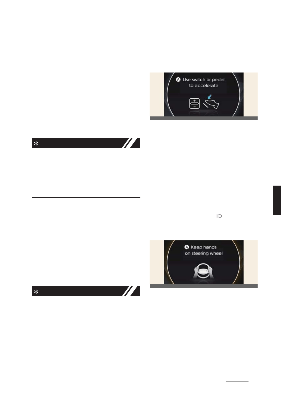
129
6
6
Driving your vehicle Highway Driving Assist (HDA)
- Grey: Standby state
- White blink: Accelerator
depressed state
- None: Off state
2
Set speed is displayed.
3
Lane Following Assist indicator dis
-
played.
4
Whether there is a vehicle ahead and
the target vehicle to vehicle distance
are displayed.
5
Whether the lane is detected or not is
displayed.
NOTICE
僅 For more details on the display, refer
to "Smart Cruise Control (SCC) (if
equipped)" on page 6-104.
僅 For more details on the display, refer
to "Lane Following Assist (LFA)" on
page 6-123.
Highway Driving Assist operating
When driving on available road, press
Drive Assist button to turn on Highway
Driving Assist.
Highway Driving Assist will operate
when entering or driving on the main
road of highways (or motorways), and
satisfying all the following conditions:
僅 Lane Following Assist is operating
僅 Smart Cruise Control is operating
NOTICE
僅 While driving on the highway (or
motorway), if Smart Cruise Control
starts operating, Highway Driving
Assist will operate.
僅 When entering the main roads of
highways (or motorways) while Smart
Cruise Control is operating, Driving
Assist will not turn on if Lane Follow
-
ing Assist is turned off.
Restarting after stopping
A:
Use switch or pedal to accelerate
When Highway Driving Assist is operat
-
ing, your vehicle will stop if the vehicle
ahead of you stops. Also, if the vehicle
ahead of you starts moving approxi
-
mately within 30 seconds after the stop,
your vehicle will start as well. In addition,
after the vehicle has stopped and
approximately 30 seconds have passed,
the
Use switch or pedal to accelerate
message will appear on the cluster.
Depress the accelerator pedal or push
the + switch, - switch or ( ) switch to
start driving.
Hands-off warning
A:
Keep hands on steering wheel
If the driver takes their hands off the
steering wheel for several seconds, the
warning message will appear and an
audible warning will sound in stages.
僅 First stage: Warning message
僅 Second stage: Warning message (red
steering wheel) and audible warning
OCV051168L
OCV051133L
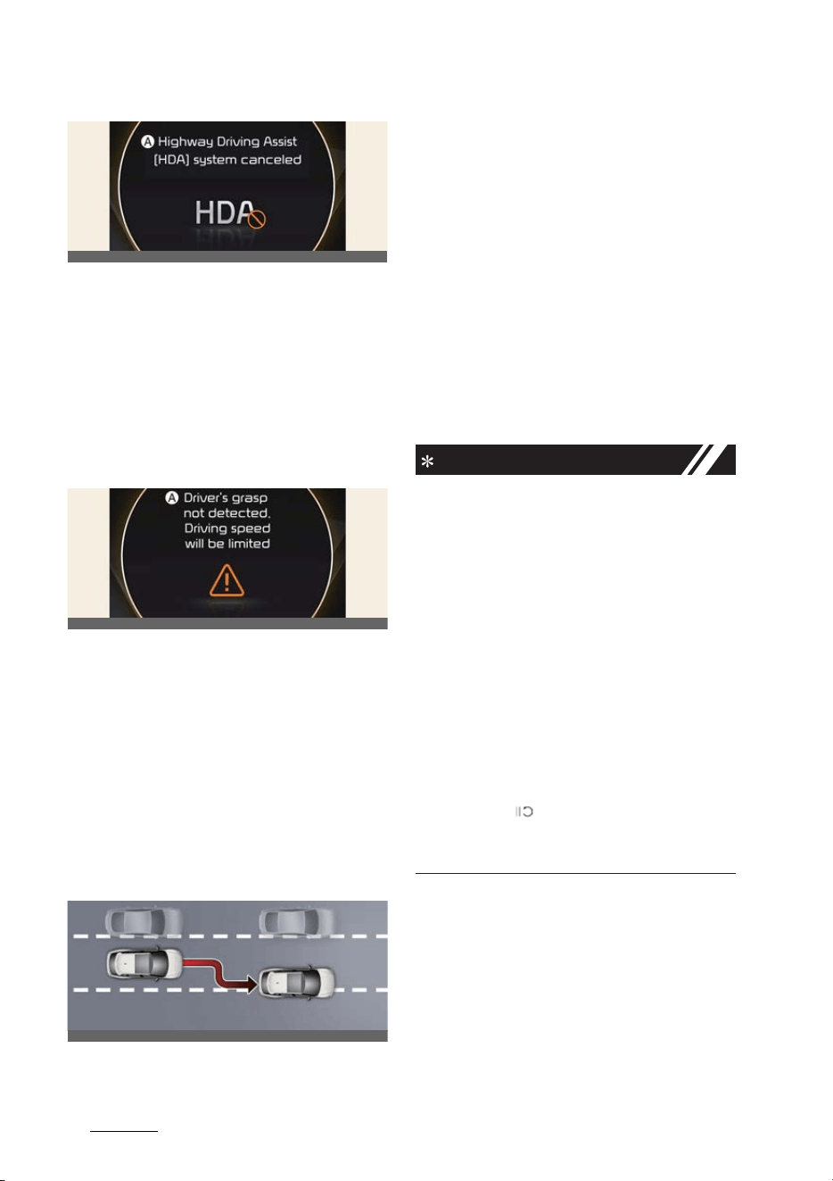
Driving your vehicle
1306
Highway Driving Assist (HDA)
A:
Highway Driving Assist (HDA) sys
-
tem canceled
If the driver still does not have their
hands on the steering wheel after the
hands-off warning, the warning mes
-
sage will appear and Highway Driving
Assist and Lane Change Assist will be
automatically canceled.
Driving speed limit
A:
Driver's grasp not detected. Driving
speed will be limited
When Highway Driving Assist is can
-
celed by the hands-off warning, The
driving speed will be limited. While Driv
-
ing Speed Limit function is operating,
the warning message will appear on the
cluster, and an audible warning will
sound continuously.
Driving to one side within lane (if
equipped)
When vehicle speed is above 60 km/h
(40 mph), if a vehicle around you is driv
-
ing at a close distance, your vehicle will
control steering in the opposite direction
of the vehicle to assist in safe driving. If
there are vehicles in both sides of the
lane that are driving close to you, the
function will not veer to the opposite
side of the lane.
Highway Driving Assist standby
When the Smart Cruise Control is tem
-
porarily canceled while Highway Driving
Assist is operating, Highway Driving
Assist will be in the standby state. At this
time, Lane Following Assist will operate
normally.
NOTICE
僅 Driving Speed Limit helps you drive
below 60 km/h (40 mph). At this time,
the vehicle decelerates due to the
vehicle ahead. After the vehicle has
decelerated, it cannot automatically
accelerate.
僅 Driving Speed Limit will cancel in the
following circumstances:
- When the driver grabs the steering
wheel again
- When the driver turns on Lane Fol
-
lowing Assist by pressing the Lane
Driving Assist button
- When Smart Cruise Control switch
+, -, or ( ) switch is pushed, or the
accelerator pedal or the brake
pedal is depressed
Highway Lane Change Assist (if
equipped)
Display and control
You can see the status of the Highway
Lane Change Assist function operation
in the Driving Assist view on the cluster.
Refer to "LCD display" on page 5-47.
OCV051179L
OCV041195L
OCV051072L
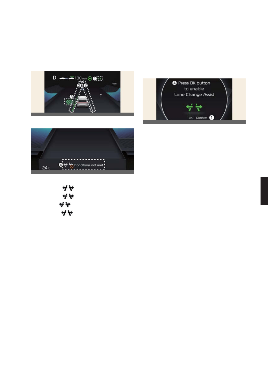
131
6
6
Driving your vehicle Highway Driving Assist (HDA)
Highway Lane Change Assist function
will be displayed as below depending on
the status of the function.
Ready/Operating
Standby/Canceled
1
Highway Lane Change Assist indicator
僅 Green ( ) on: Ready state
僅 Green ( ) blink: Operating state
僅 Grey ( ) on: Standby state
僅 White ( ) blink: Canceled state
(display only a certain time)
2
Lane line
The lane line is displayed identical to
Highway Lane Change Assist indicator
(1). However, the lane detection avail
-
ability will be showed on Standby
state.
3
Green arrow and shade
The green arrow is displayed when a
certain amount of time has passed
after the function has started operat
-
ing, and until the lane change has
completed.
4
Message
僅 Message is displayed when the
function does not operate even
though the turn signal lever is used.
僅 Message is displayed when the
function is canceled while operat
-
ing.
To turn on Highway Lane Change
Assist
A:
Press OK button to enable Lane
Change Assist
1 Confirm
Highway Lane Change Assist function
will turn on when the following condi
-
tions are satisfied.
僅 The Driving Assist button or Lane
Driving Assist button is used to turn
on Highway Driving Assist.
僅The OK button is pressed on the
steering wheel while a message ask
-
ing to use Highway Lane Change
Assist is displayed on the cluster.
Highway Lane Change Assist
ready to operate
While Highway Lane Change Assist
function is on, the function will be ready
to operate when all the following condi
-
tions are satisfied:
僅 Highway Driving Assist is operating
僅 Lane Following Assist is operating
僅 A vehicle in the rear area of your vehi
-
cle is detected more than once after
the vehicle is turned on
僅 Your vehicle speed is above 80 km/h
(50 mph)
僅 Hands-off warning is not displayed on
the cluster
僅 Hazard warning flasher is off
OCV041263L
OCV051221L
OCV051210L
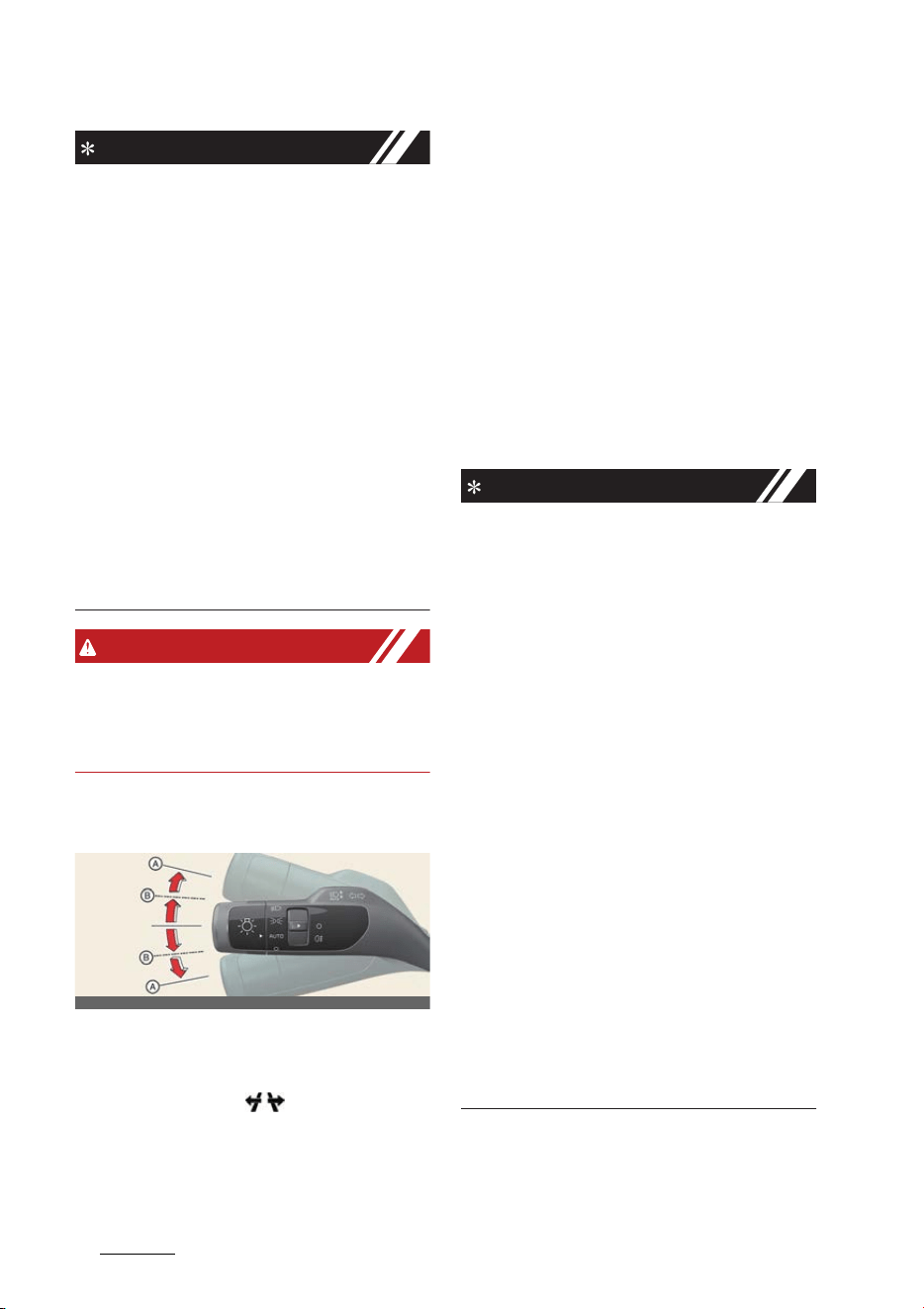
Driving your vehicle
1326
Highway Driving Assist (HDA)
NOTICE
僅 While Lane Change Assist function is
turned on (indicator on), Lane Follow
-
ing Assist will not cancel even if the
turn signal indicator or hazard warn
-
ing flasher is operating.
僅 Lane Change Assist function turns off
automatically when driven in the fol
-
lowing road conditions:
- One driving lane
- A road with no structure, such as a
medium strip, guardrails, etc.
- There is a pedestrian or cyclist on
the road ahead
僅 When the function is in the ready
state, and vehicle speed is below 75
km/h (45 mph), the function will
change to the standby state.
WARNING
When Highway Lane Change Assist
function turns off while operating, steer
-
ing assist will be temporarily canceled.
Always be cautious while driving.
Highway Lane Change Assist
operating
Highway Lane Change Assist function
will operate, when you push the turn sig
-
nal lever up or down while the function is
in the ready state (( ) indicator is
green), and all of the following condi
-
tions are satisfied:
僅 The driver has his/her hand on the
steering wheel
僅 There is no collision risk in the direc
-
tion of lane change
僅 There is a single dotted lane line in the
direction of lane change
僅 There are no Forward Collision-Avoid
-
ance Assist and Blind Spot Collision-
Avoidance Assist warnings
僅 The vehicle is driven in the middle of
the lane (should not be driving close
to one side of the lane)
僅 The road you are driving on, or the
road you are about to change lane is a
road that the function can operate
NOTICE
僅 When the turn signal lever is placed at
A position, the Highway Lane Change
Assist function is performed. After
that, if the turn signal lever is placed
in neutral, Highway Lane Change
Assist function is canceled before
stepping on the lane.
The Highway Lane Change Assist
function is not canceled after stepping
on the lane, but when the lane change
is completed, it is canceled and the
turn signal turns off.
僅 When the turn signal lever is placed at
B position for a certain period of time,
the green arrow will appear. At this
time, even when the lever is released
and returns to it's original position,
lane change will still be assisted.
While lane change is being made by
the function, the turn signal indicator
will blink even when the turn signal
lever is not held, and the turn signal
indicator will turn off when lane
change is complete.
OCV051059L

133
6
6
Driving your vehicle Highway Driving Assist (HDA)
Highway Lane Change Assist
standby
Highway Lane Change Assist function
will be in the standby state when one of
the ready state condition is not satisfied,
or when entering or driving on one of
the following roads:
僅 Road within a certain distance from
the tollgate on the main road of the
highway (or motorway)
僅 The road ahead ends without an inter
-
change or junction
僅 Road with sharp curves
僅 Road with narrow lanes
僅 Road that is under construction
Highway Lane Change Assist
cancel
The function will be canceled when:
僅 The turn signal lever is tuned off
before changing lane during High
-
way Driving Assist operation.
僅 The turn signal lever is turned on in
the opposite direction of lane change
僅 The steering wheel is steered sharply
WARNING
僅 While the function is operating, the
function will cancel if one of the fol
-
lowing occurs:
- Highway Driving Assist is turned off
- Lane Following Assist or Smart
Cruise Control is turned off or tem
-
porarily canceled
- Hands-off warning message is dis
-
played on the cluster
- The turn signal lever is placed at A
position
- The hazard warning flasher is
turned on
- Forward Collision-Avoidance Assist
or Blind-Spot Collision-Avoidance
Assist warning message is dis
-
played
- Possible collision is detected in the
next lane, even though there are no
Forward Collision-Avoidance Assist
and Blind Spot Collision-Avoidance
Assist warning
- Entering a road under construction
- The target lane to make a lane
change disappears
- The target lane to make a lane
change is not detected
- There is a problem with turn signal
lamps
- Highway Lane Change Assist func
-
tion is off (The function turns off
when the function is turned off
from the settings menu, when the
road changes to a one-way road,
when there is a intersection or
crosswalk ahead, when you enter a
road with no structure, such as a
medium strip, guardrail, etc., or
when there is a pedestrian or cyclist
on the driving lane.)
- Your vehicle speed is below 75 km/
h (45 mph)
僅 While the function is operating, when
the function is canceled, depending
on the driving conditions, the vehicle
may drive to the middle of the driving
lane or steering assist may stop.
Always pay attention to road and driv
-
ing conditions while driving.
僅 The function may not operate nor
-
mally on roads with pedestrians or
cyclists, such as an intersection or
crosswalk. Always pay attention to
road and driving conditions while
driving.
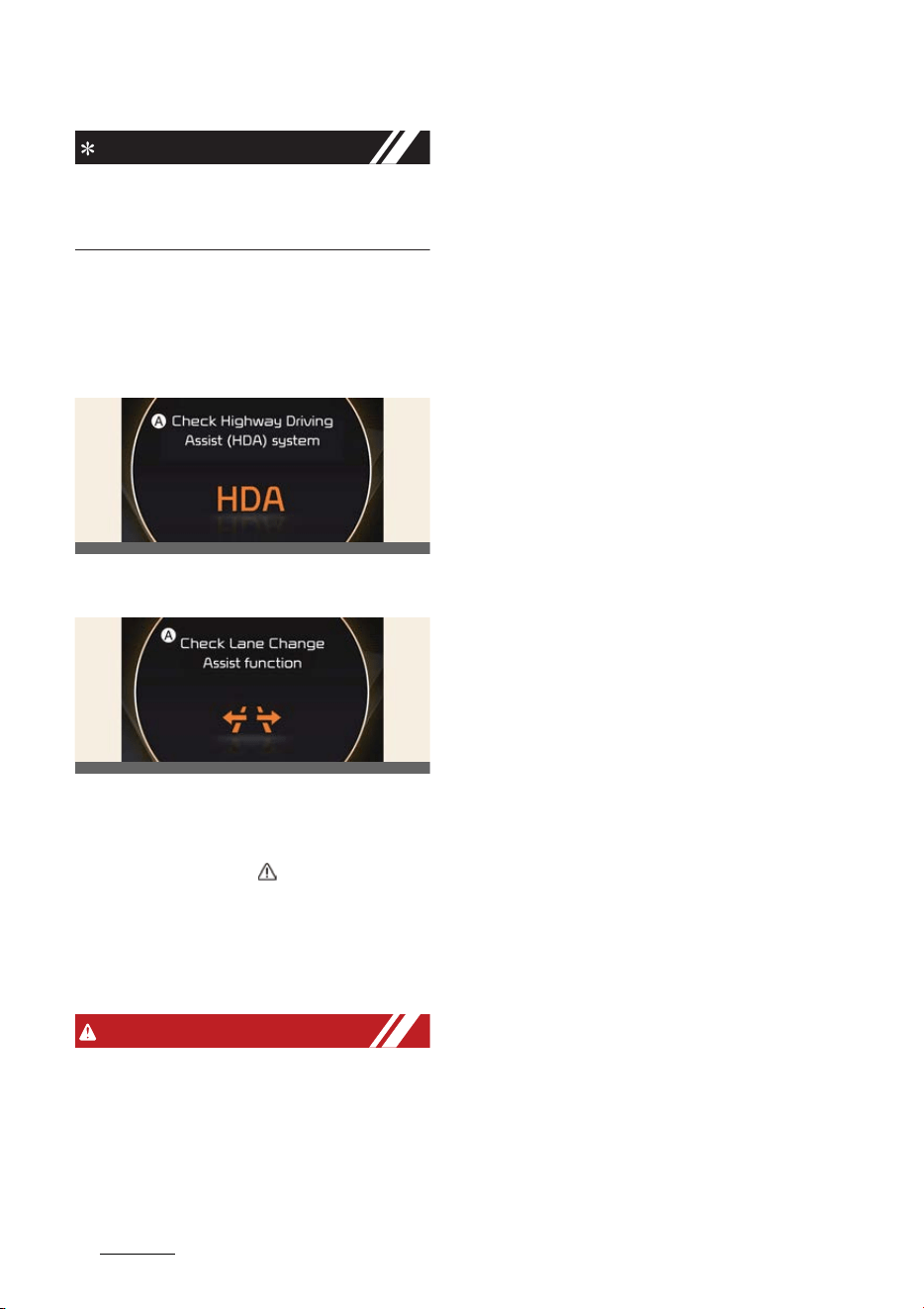
Driving your vehicle
1346
Highway Driving Assist (HDA)
NOTICE
The images or colors may be displayed
differently depending on the specifica
-
tions of the instrument cluster or theme.
Highway Driving Assist malfunc
-
tion and limitations
Highway Driving Assist malfunc
-
tion
A:
Check Highway Driving Assist
(HDA) system
A:
Check Lane Change Assist function
When Highway Driving Assist is not
working properly, the warning message
will appear, and the ( ) warning light
will illuminate on the cluster. Have High
-
way Driving Assist be inspected by a
professional workshop. Kia recommends
visiting an authorized Kia dealer/service
partner.
WARNING
僅 The driver is responsible for con
-
trolling the vehicle for safe driving.
僅 Always have your hands on the steer
-
ing wheel while driving.
僅 Highway Driving Assist is a supple
-
mental function that assists the driver
in driving the vehicle and is not a
complete autonomous driving system.
Always check road conditions, and if
necessary, take appropriate actions to
drive safely.
僅 Always have your eyes on the road,
and it is the responsibility of the driver
to avoid violating traffic laws. The
vehicle manufacturer is not responsi
-
ble for any traffic violation or acci
-
dents caused by the driver.
僅 Highway Driving Assist may not be
able to recognize all traffic situations.
The function may not detect possible
collisions due to Limitations. Always
be aware of the Limitations. Obstacles
such as vehicles, motorcycles, bicy
-
cles, pedestrians, guardrails, tollgate,
unspecified objects, structures, etc.
that may collide with the vehicle may
not be detected.
僅 Highway Driving Assist will turn off
automatically under the following sit
-
uations:
- Driving on roads that the function
does not operate, such as a rest
area, intersection, junction, etc.
- The navigation does not operate
properly such as when the naviga
-
tion is being updated or restarted
僅 Highway Driving Assist may inadver
-
tently operate or turn off depending
on road conditions (navigation infor
-
mation) and surroundings.
僅 Lane Following Assist function may be
temporarily disabled when the front
view camera cannot detect lanes
properly or the hands-off warning is
on.
僅 You may not hear the warning sound
of Highway Driving Assist if the sur
-
rounding is noisy.
OCV051180L
OCV041196L

135
6
6
Driving your vehicle Highway Driving Assist (HDA)
僅 If the vehicle is driven at high speed
above a certain speed at a curve, your
vehicle may drive to one side or may
depart from the driving lane.
僅 When you are towing a trailer or
another vehicle, we recommend that
Highway Driving Assist is turned off
due to safety reasons.
僅 The hands–off warning message may
appear early or late depending on
how the steering wheel is held or road
conditions. Always have your hands
on the steering wheel while driving.
僅 For your safety, please read the
owner's manual before using the
Highway Driving Assist.
僅 Highway Driving Assist will not oper
-
ate when the vehicle is started, or
when the detecting sensors or naviga
-
tion is being initialized.
Limitations of Highway Driving
Assist
Highway Driving Assist and Highway
Lane Change function may not operate
normally, or may not operate under the
following circumstances:
僅 The map information and the actual
road is different because the naviga
-
tion is not updated
僅 The map information and the actual
road is different because of real-time
GPS data or map information error
僅 The infotainment system is over
-
loaded by simultaneously performing
functions such as route search, video
playback, voice recognition, etc.
僅 GPS signals are blocked in areas such
as a tunnel
僅 The driver goes off course or the
route to the destination is changed or
canceled by resetting the navigation
(including TPEG change)
僅 The vehicle enters a service station or
rest area
僅 Android Auto or Car Play is operating
僅 The navigation cannot detect the cur
-
rent vehicle position (ex: elevated
roads including overpass adjacent to
general roads or nearby roads exist in
a parallel way)
僅 White single dotted lane line or road
edge cannot be detected
僅 The road is temporarily controlled due
to construction, etc.
僅 There is no structure, such as a
medium strip, guardrails, etc., on the
road
僅 There is a changeable lane in the
direction of lane change
NOTICE
For more details on the limitations of the
front view camera and front radar, refer
to "Forward Collision-Avoidance Assist
(FCA) (if equipped)" on page 6-43.
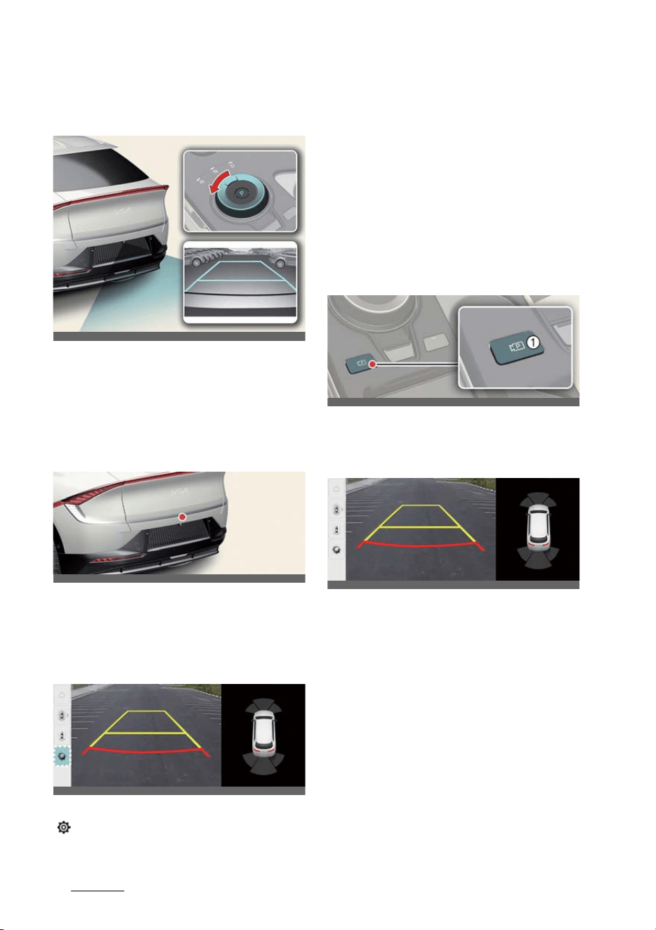
Driving your vehicle
1366
Rear View Monitor (RVM)
Rear View Monitor (RVM) (if
equipped)
Rear View Monitor will show the area
behind the vehicle to assist you when
parking or Reversing.
Detecting sensor
Wide-rear view camera
Refer to the picture above for the
detailed location of the detecting sensor.
Rear View Monitor settings
Camera settings
With the vehicle on, select the setup icon
( ) on the screen or
Settings
→
Vehicle
→
Driver assistance
→
Parking safety
→
Camera settings
from the infotain
-
ment system screen to change the Rear
View Monitor settings.
僅 Display Contents: To change the set
-
tings of Extended Rear View Monitor,
and Rear View Parking Guide Lines.
僅 Display Settings: To change the
screen's brightness and contrast.
Rear View Monitor operation
Parking/View button
Press the Parking/View button (1) to turn
on or off Rear View Monitor.
Rear view
Operating conditions
Rear View Monitor will turn on when the
following conditions are satisfied:
僅 Shifting the gear to R (Reverse).
僅 Pressing the Parking/View button (1)
while P (Park) gear position is selected
僅 Pressing the View icon with the Rear
top view on the screen
Off conditions
Rear View Monitor will turn off when the
following conditions are satisfied:
OCV041043L_2
OCVGT042642L
OCV051194L
OCV041045L
OCV051229L
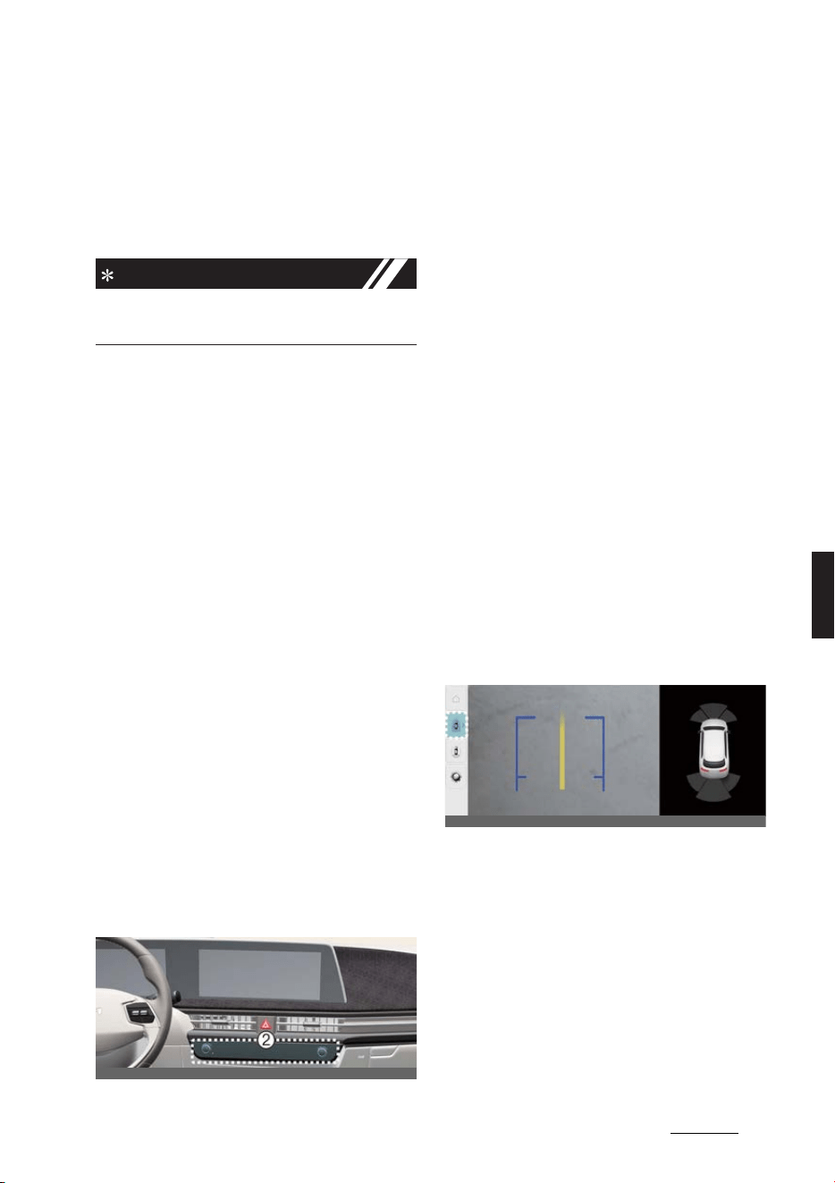
137
6
6
Driving your vehicle Rear View Monitor (RVM)
僅 Pressing the Parking/View button (1)
again while P (Park) gear position is
selected. with the rear view on the
screen.
僅Changing the gear from R (Reverse)
to P (Park).
NOTICE
The rear view cannot be turned off when
the gear is in R (Reverse).
Extended Rear View Monitor
Extended Rear View Monitor maintains
the rear view of the vehicle when shift
-
ing the gear from R (Reverse) to N (Neu
-
tral) or D (Drive) to help you park safely.
Operating conditions
Rear View Monitor will maintain when
the following conditions are satisfied:
僅 Shifting the gear from R (Reverse) to
N (Neutral) or D (Drive).
僅 The vehicle speed is below approxi
-
mately 10 km/h (6 mph).
Off conditions
Extended rear view function will turn off
when one the following conditions are
satisfied:
僅 The vehicle speed is above approxi
-
mately 10 km/h (6 mph).
僅 Pressing the Parking/View button (1).
僅 Shifting the gear to P (Park).
Rear view while driving
The driver is able to check the rear view
on the screen while driving, it is to assist
with safe driving.
Operating conditions
Press the Parking/View button (1) while
the gear is in D (Drive) or N (Neutral), the
driving rear view will appear on the
screen.
Off conditions
Rear view while driving function will turn
off when one the following conditions
are satisfied:
僅 Pressing the Parking/View button (1)
or the infotainment system button (2).
僅 Shifting the gear to P (Park).
Function operation
If the vehicle is in R (Reverse) during
Rear view driving, the screen will change
to rear view with parking guidance.
Rear top view
Rear top view shows the distance from
the vehicle or the object in the back of
your vehicle while parking.
Press the Rear top view button to turn
on Rear top view.
Rear View Monitor malfunction
and limitations
Rear View Monitor malfunction
When Rear View Monitor is not working
properly, or the screen flickers, or the
OCV051196L
OCV051197L
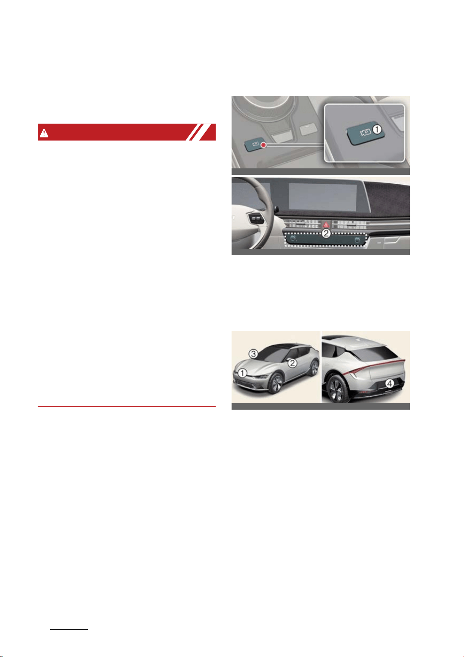
Driving your vehicle
1386
Surround View Monitor (SVM)
camera image does not display nor
-
mally, Kia recommends visiting an
authorized Kia dealer/service partner.
Limitations of Rear View Monitor
WARNING
僅 The rear view camera does not cover
the complete area behind the vehicle.
The driver should always check the
rear area directly through the inside
and outside rear view mirror before
parking or Reversing.
僅 The image shown on the screen may
differ from the actual distance of the
object. Make sure to directly check the
vehicle's surroundings for safety.
僅 Always keep the rear view camera
lens clean. If the lens is covered with
foreign material, it may adversely
affect camera performance and Rear
View Monitor may not operate nor
-
mally. However, do not use chemical
solvents such as strong detergents
containing high alkaline or volatile
organic solvents (gasoline, acetone
etc.). This may damage the camera
lens.
Surround View Monitor (SVM)
(if equipped)
Surround View Monitor can assist in
parking by allowing the driver to see
around the vehicle.
Detecting sensor
僅 1: SVM-front view camera
僅 2, 3: SVM-side view camera (under the
side view mirror)
僅 4: SVM-rear view camera
Refer to the picture above for the
detailed location of the detecting sen
-
sors.
OCV041045L
OCV051196L
OCV041046L_2
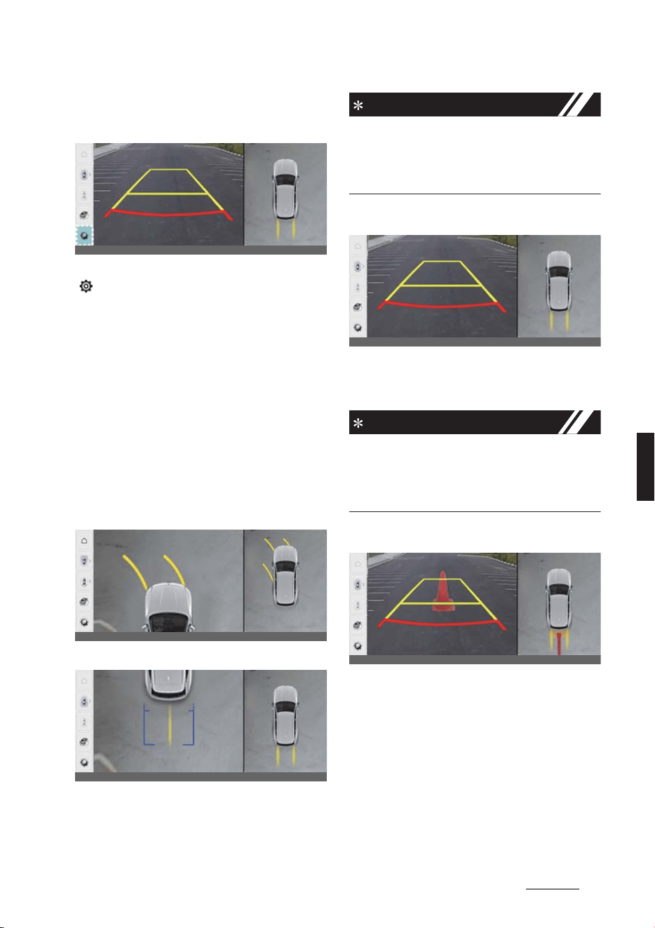
139
6
6
Driving your vehicle Surround View Monitor (SVM)
Surround View Monitor settings
Camera settings
With the vehicle on, select the setup icon
( ) on the screen or
Settings
→
Vehicle
→
Driver assistance
→
Parking safety
→
Camera settings
from the infotain
-
ment system screen to change the Rear
View Monitor settings.
僅 Display Contents: To change the set
-
tings of
Top view parking guidance
,
Parking guide in rear view
, and
Parking distance warning
function.
僅 Display Settings: To change the
screen's brightness and contrast.
Top View Parking Guidance
Front top view
Rear top view
Parking guidance is displayed on the
right side of the Surround View Monitor
screen when the
Front or Rear Top
View Parking Guidance
is selected.
NOTICE
The horizontal guideline of the Rear Top
View Parking Guidance shows the tail
-
gate opening distance and the distance
of 2 m from the vehicle.
Rear View Parking Guidance
Rear view parking guidance is displayed
in the rear view when the
Parking guide
in rear view
is selected.
NOTICE
The horizontal guideline of the Rear
View Parking Guidance shows the dis
-
tance of 0.5 m (1.6 ft.), 1 m (3.3 ft.) and
2.3 m (7.6 ft.) from the vehicle.
Parking Distance Warning
Parking distance warning is displayed on
the right side of the Surround View Mon
-
itor top view screen when the
Parking
distance warning
is selected.
Surround View Monitor Auto On
With the vehicle on, select
Settings
→
Vehicle
→
Driver assistance
→
Parking
safety
→
Surround view monitor auto
On
from the infotainment system screen
to use the function.
OCV051198K
OCV051199K
OCV051200K
OCV051201K
OCV051254L
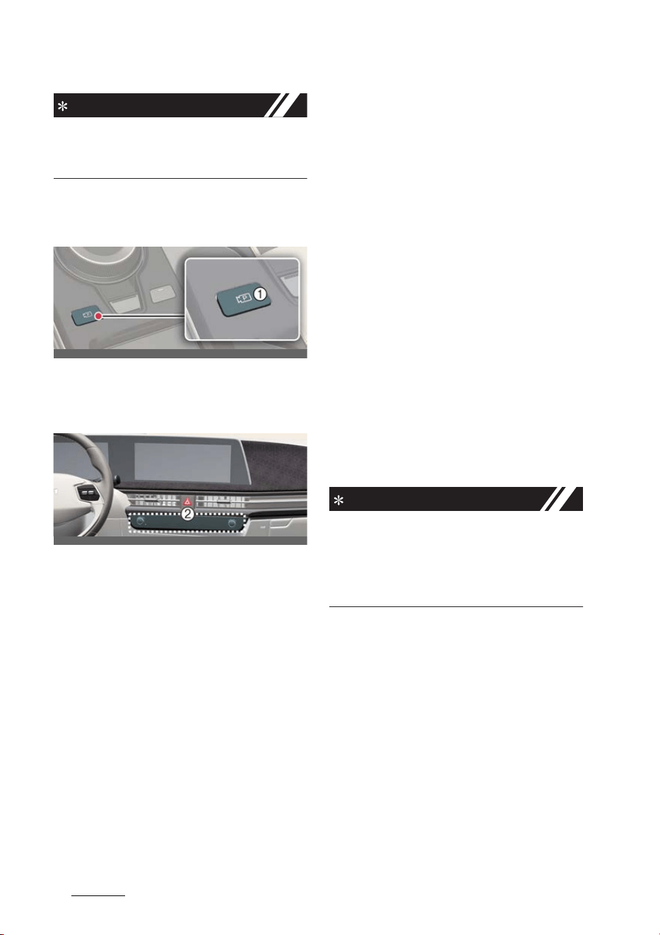
Driving your vehicle
1406
Surround View Monitor (SVM)
NOTICE
For more details on Surround View Mon
-
itor Auto On, refer to "Surround View
Monitor Auto On" on page 6-139.
Surround View Monitor operation
Parking/View button
Press the Parking/View button (1) to turn
on or off Surround View Monitor.
Front view
Front view function is displayed on the
screen when the gear is in N (Neutral) or
D (Drive) to assist in parking. The front
view has a top view, front view, side view
and 3D view. Also, other view modes can
be selected by pressing the view icons
on the Surround View Monitor screen.
Operating conditions
Front view function will turn on when the
following conditions are satisfied:
僅 Shifting from R (Reverse) to N (Neu
-
tral) or D (Drive) and the vehicle speed
is below approximately 10 km/h (6
mph).
僅 Pressing the Parking/View button (1)
when the gear is in D (Drive) or N
(Neutral) and vehicle speed is below
10 km/h (6 mph).
僅 Forward Parking Distance Warning
warns the driver while driving in D
(Drive) (
Settings
→
Vehicle
→
Driver
assistance
→
Parking safety
→
Sur
-
round view monitor auto On
selected from the infotainment sys
-
tem screen)
Off conditions
Front view function will turn off when
the following conditions are satisfied:
僅 Press the Parking/View button (1) or
the infotainment system button (2).
僅 When vehicle speed is above 10 km/h
(6 mph).
僅 Press one of the infotainment system
button (2), the screen will change to
the infotainment system screen.
僅Shifting to P (Park).
NOTICE
If the Surround View Monitor is turned
off after driving more than 10 km/h (6
mph), driving below 10 km/h (6 mph)
again will not switch to the Surround
View Monitor screen.
Rear view
Rear view function is displayed on the
screen when the gear is in R (Reverse) or
P (Park) to assist in parking. The rear
view has a top view, rear view, side view
and 3D view. Also, other view modes can
be selected by pressing the view icons
on the Surround View Monitor screen.
Operating conditions
Rear view function will turn on when the
following conditions are satisfied:
僅 Shifting to R (Reverse).
OCV041045L
OCV051196L

141
6
6
Driving your vehicle Surround View Monitor (SVM)
僅 Pressing the Parking/View button (1)
when P (Park) gear position is
selected.
Off conditions
Rear view function will turn off when the
following conditions are satisfied:
僅 Shifting from R (Reverse) to P (Park).
僅 Pressing the Parking/View button (1)
when P (Park) gear position is
selected.
NOTICE
Pressing the infotainment system button
(2) will not turn the rear view off when
the gear is in R (Reverse).
Rear view while driving
The driver is able to check the rear view
on the screen while driving, it is to assist
with safe driving.
Operating conditions
Rear view while driving function will turn
on when the following conditions are
satisfied:
僅 Pressing the Parking/View button (1)
when the vehicle speed is above 10
km/h (6 mph).
僅 Pressing the view icon on the Sur
-
round View Monitor screen when the
vehicle speed is below 10 km/h (6
mph).
Off conditions
Rear view while driving function will turn
off when the following conditions are
satisfied:
僅 Pressing the Parking/View button (1)
or the infotainment system button (2).
僅Shifting to P (Park).
僅 Pressing the other view icon on the
Surround View Monitor screen when
the vehicle speed is below 10 km/h (6
mph).
Surround View Monitor malfunc
-
tion and limitations
Surround View Monitor malfunc
-
tion
When Surround View Monitor is not
working properly, or the screen flickers,
or the camera image does not display
normally, Kia recommends visiting an
authorized Kia dealer/service partner.
Limitations of Surround View
Monitor
僅 The screen may be displayed abnor
-
mally, and an icon will appear at the
top left side of the screen under the
following circumstances:
- The tailgate is opened.
- The driver or front passenger door
is opened.
- The outside rear view mirror is
folded.
WARNING
僅 ALWAYS look around your vehicle to
make sure there are no objects or
obstacles before moving the vehicle.
What you see on the screen may dif
-
fer from the actual vehicle's location.
僅 The image shown on the screen may
differ from the actual distance of the
object. Make sure to directly check the
vehicle's surroundings for safety.
僅 Surround View Monitor is designed to
be used on a flat surface. Therefore, if
used on roads with different heights
such as curbs and speed bumps, the
image in the screen my not look cor
-
rect.
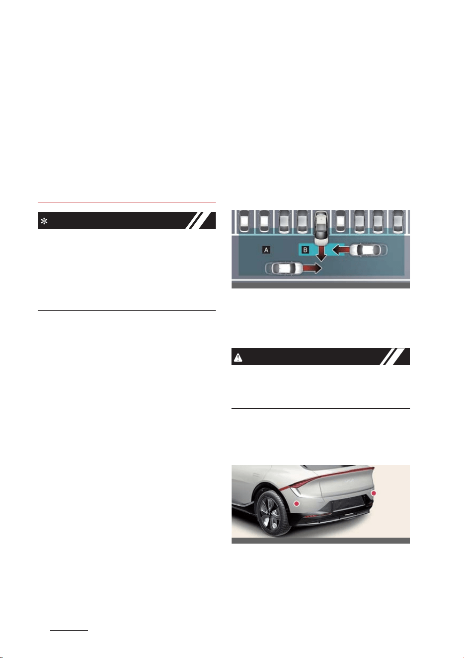
Driving your vehicle
1426
Rear Cross-Traffic Collision-Avoidance Assist (RCCA)
僅 Always keep the camera lens clean. If
the lens is covered with foreign mate
-
rial, it may adversely affect camera
performance and Surround View
Monitor may not operate normally.
However, do not use chemical sol
-
vents such as strong detergents con
-
taining high alkaline or volatile
organic solvents (gasoline, acetone
etc.). This may damage the camera
lens.
NOTICE
僅 When Rear View while Driving is on, it
stays on while driving regardless of
vehicle speed.
僅 When Rear View while Driving is on
while Reversing, the screen changes
to the rear view.
Rear Cross-Traffic Collision-
Avoidance Assist (RCCA) (if
equipped)
Rear Cross-Traffic Collision-Avoidance
Assist is designed to help detect vehicles
approaching from blind spot area while
your vehicle is reversing, and warn the
driver that a collision is imminent with a
warning message and an audible warn
-
ing. Also, braking is assisted to help pre
-
vent collision.
[A]: Rear Cross-Traffic Collision Warning
operating range
[B]: Rear Cross-Traffic Collision-Avoid
-
ance Assist operating range
CAUTION
The time of warning may vary depend
-
ing on vehicle speed of the approaching
vehicle.
Detecting sensor
Rear corner radar
Refer to the picture above for the
detailed location of the detecting sensor.
OCV051075L
OCV051025L
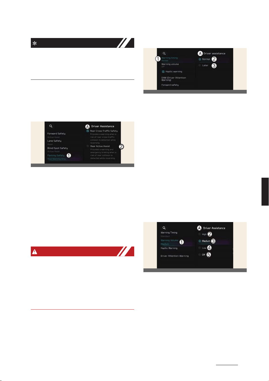
143
6
6
Driving your vehicle Rear Cross-Traffic Collision-Avoidance Assist (RCCA)
NOTICE
For more details on the precautions of
the rear corner radar, refer to "Blind-
Spot Collision-Avoidance Assist (BCA) (if
equipped)" on page 6-67.
Rear Cross-Traffic Collision-
Avoidance Assist settings
Rear Cross-Traffic Safety
A:
Driver assistance
1 Parking safety
2 Rear cross-traffic safety
With the vehicle on, select
Settings
→
Vehicle
→
Driver assistance
→
Parking
safety
→
Rear cross-traffic safety
from the infotainment system screen to
turn on Rear Cross-Traffic Collision-
Avoidance Assist and deselect to turn off
the function.
WARNING
When the vehicle is restarted, Rear
Cross-Traffic Collision-Avoidance Assist
will automatically turn on. However, if
Off
is selected after the vehicle is
restarted, the driver should always be
aware of the surroundings and drive
safely.
Warning Timing
A:
Driver assistance
1 Warning timing
2 Normal
3 Late
With the vehicle on, select
Settings
→
Vehicle
→
Driver assistance
→
Warn
-
ing timing
from the infotainment sys
-
tem screen to change the initial warning
activation time for Rear Cross-Traffic
Collision-Avoidance Assist.
When the vehicle is first delivered, Warn
-
ing Timing is set to
Normal
. If you
change the Warning Timing, the warning
time of other Driver Assistance systems
may change.
Warning volume
A:
Driver assistance
1 Warning volume
2 High
3 Medium
4 Low
5 Off
With the vehicle on,
Settings
→
Vehicle
→
Driver assistance
→
Warning vol
-
ume
on the infotainment system to
change the Warning volume to adjust
OCV041577L
OCVGT042587L
OCV041562L
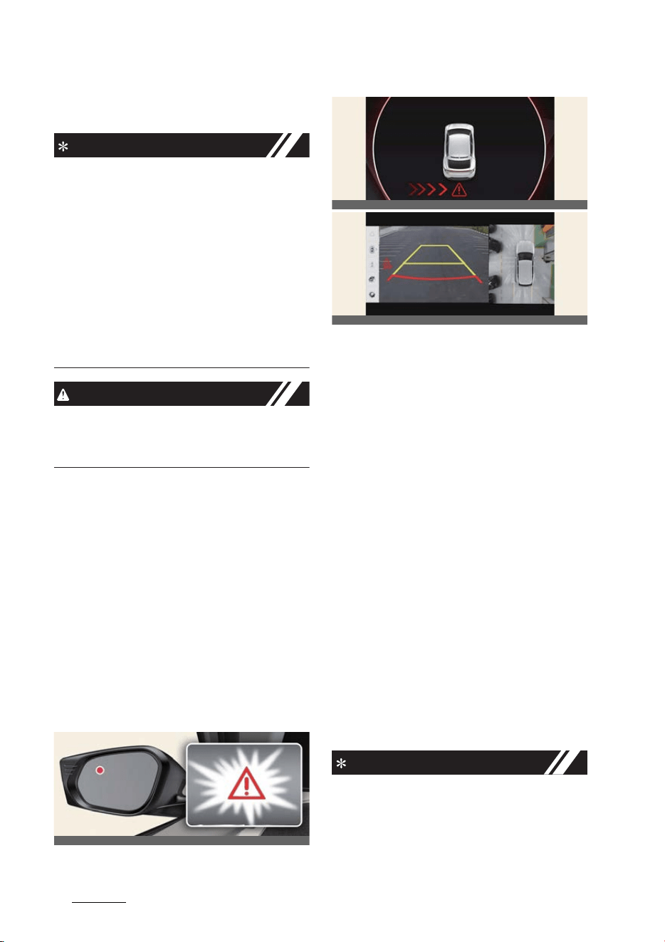
Driving your vehicle
1446
Rear Cross-Traffic Collision-Avoidance Assist (RCCA)
the Warning volume levels;
High
,
Medium
,
Low
or
Off
.
NOTICE
僅 If the vehicle is restarted, Warning vol
-
ume will maintain the last setting.
僅If
Off
is selected, the Warning volume
of Rear Cross-Traffic Collision-Avoid
-
ance Assist will not turn off, but the
volume will sound as
Low
.
僅If
Off
is selected, steering wheel
vibration will not turn off.
僅 If you change the Warning volume,
the Warning volume of other Driver
Assistance systems may change.
CAUTION
The settings for Warning Volume applies
to all the functions of Rear Cross-Traffic
Collision-Avoidance Assist.
Rear Cross-Traffic Collision-
Avoidance Assist operation
Warning and control
Rear Cross-Traffic Collision-Avoidance
Assist will warn and control the vehicle
depending on collision level
僅 Collision Warning
僅Emergency Braking
僅 Stopping vehicle and ending brake
control
Collision warning
僅 To warn the driver of an approaching
vehicle from the rear left/right side of
your vehicle, the warning light on the
outside rear view mirror will blink and
a warning will appear on the cluster.
At the same time, an audible warning
will sound and the steering wheel will
vibrate. If the Rear View Monitor is
operating, a warning will also appear
on the infotainment system screen. (if
equipped)
僅 Rear Cross-Traffic Collision-Avoid
-
ance Assist will operate when all the
following conditions are satisfied:
- The gear is shifted to R (Reverse)
and the vehicle speed is below 8
km/h (5 mph)
- The approaching vehicle is within
approximately 25 m (82 ft.) from
the blind spot area of your vehicle
- The speed of the vehicle approach
-
ing from the blind spot area is
above 5 km/h (3 mph)
NOTICE
If the operating conditions are satisfied,
there will be a warning whenever the
vehicle approaches from the left or right
OCV051038L
OCV051181L
OCV041204K
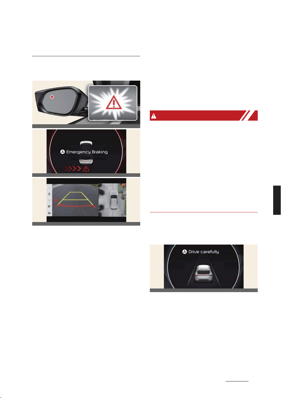
145
6
6
Driving your vehicle Rear Cross-Traffic Collision-Avoidance Assist (RCCA)
side even though your vehicle speed is 0
km/h (0 mph).
Emergency braking
A:
Emergency braking
僅 To warn the driver of an approaching
vehicle from the rear left/right side of
your vehicle, the warning light on the
outside rear view mirror will blink and
a warning message will appear on the
cluster. At the same time, an audible
warning will sound and the steering
wheel will vibrate. If the Rear View
Monitor is operating, a warning will
also appear on the infotainment sys
-
tem screen. (if equipped)
僅 Rear Cross-Traffic Collision-Avoid
-
ance Assist will operate when all the
following conditions are satisfied:
- The gear is shifted to R (Reverse)
and the vehicle speed is below 8
km/h (5 mph)
- The approaching vehicle is within
approximately 1.5 m (5 ft.) from the
blind spot area of your vehicle
- The speed of the vehicle approach
-
ing from the left and right is above
5 km/h (3 mph)
僅 Emergency braking will be assisted to
help prevent collision with approach
-
ing vehicles from the blind spot area.
WARNING
Brake control will end:
僅 The approaching vehicle is out of the
detecting range
僅 The approaching vehicle passes
behind your vehicle
僅 The approaching vehicle does not
drive toward your vehicle
僅 The approaching vehicle speed slows
down
僅 The driver depresses the brake pedal
with sufficient power
Stopping vehicle and ending
brake control
A:
Drive carefully
僅 When the vehicle is stopped due to
emergency braking, the warning mes
-
sage will appear on the cluster. For
your safety, the driver should depress
the brake pedal immediately and
check the surroundings.
- Brake control will end after the
vehicle is stopped by emergency
OCV051038L
OCV051182L
OCV041204K
OCV051118L

Driving your vehicle
1466
Rear Cross-Traffic Collision-Avoidance Assist (RCCA)
braking for approximately 2 sec
-
onds.
- During emergency braking, braking
control by the function will auto
-
matically cancel when the driver
excessively depresses the brake
pedal.
WARNING
Take the following precautions when
using Rear Cross-Traffic Collision-Avoid
-
ance Assist:
僅 For your safety, set the Settings after
parking the vehicle at a safe location.
僅 If any other function's warning mes
-
sage is displayed or audible warning
is generated, Rear Cross-Traffic
Safety function's warning message
may not be displayed and audible
warning may not be generated.
僅 You may not hear the warning sound
of Rear Cross-Traffic Collision-Avoid
-
ance Assist if the surrounding is noisy.
僅 Rear Cross-Traffic Collision-Avoid
-
ance Assist may not operate if the
driver applies the brake pedal to avoid
collision.
僅 During Rear Cross-Traffic Safety
Function Operation, the vehicle may
stop suddenly injuring passengers
and shifting loose objects. Always
have the seat belt on and keep loose
objects secured.
僅 Even if there is a problem with Rear
Cross-Traffic Collision-Avoidance
Assist, the vehicle's basic braking per
-
formance will operate normally.
僅 Rear Cross-Traffic Collision-Avoid
-
ance Assist does not operate in all sit
-
uations or cannot avoid all collisions.
僅 When Rear Cross-Traffic Collision-
Avoidance Assist is operating, braking
control by the function will automati
-
cally cancel when the driver exces
-
sively depresses the accelerator
pedal.
僅 Rear Cross-Traffic Collision- Avoid
-
ance Assist may warn the driver late
or may not warn the driver depending
on the road and driving conditions.
僅 The driver should hold the responsi
-
bility to control the vehicle. Do not
solely depend on Rear Cross-Traffic
Collision-Avoidance Assist. Rather,
maintain a safe braking distance, and
if necessary, depress the brake pedal
to reduce driving speed or to stop the
vehicle.
僅 Never deliberately operate Rear
Cross-Traffic Collision-Avoidance
Assist on people, animal, objects, etc.
It may cause serious injury or death.
CAUTION
The brake control may not operate
properly depending on the status of ESC
(Electronic Stability Control).
There will only be a warning when:
僅 The ESC (Electronic Stability Control)
warning light is on
僅 ESC (Electronic Stability Control) is
engaged in a different function
NOTICE
If braking is assisted by Rear Cross-Traf
-
fic Collision-Avoidance Assist, the driver
must immediately depress the brake
pedal and check vehicle surroundings.
僅 Brake control will end when the driver
depresses the brake pedal with suffi
-
cient power.
僅 After shifting the gear to R (Reverse),
braking control will operate once for
left and right vehicle approach.
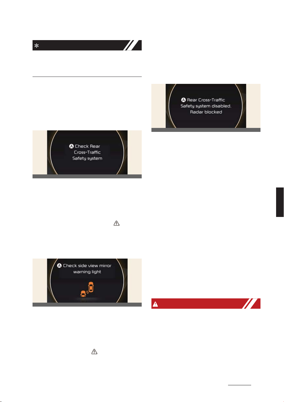
147
6
6
Driving your vehicle Rear Cross-Traffic Collision-Avoidance Assist (RCCA)
NOTICE
The images or colors may be displayed
differently depending on the specifica
-
tions of the instrument cluster or theme.
Rear Cross-Traffic Collision-
Avoidance Assist malfunction
and limitations
Rear Cross-Traffic Collision-
Avoidance Assist malfunction
A:
Check Rear Cross-Traffic Safety
system
When Rear Cross-Traffic Collision-
Avoidance Assist is not working prop
-
erly, the warning message will appear
and the master warning light ( ) will
illuminate on the cluster. Have the func
-
tion be inspected by a professional
workshop. Kia recommends visiting an
authorized Kia dealer/service partner.
A:
Check side view mirror warning
light
When the outside rear view mirror warn
-
ing light is not working properly, the
warning message will appear and the
master warning light ( ) will illuminate
on the cluster. Have the function be
inspected by a professional workshop.
Kia recommends visiting an authorized
Kia dealer/service partner.
Rear Cross-Traffic Collision-
Avoidance Assist disabled
A:
Rear Cross-Traffic Safety system
disabled. Radar blocked
When the rear bumper around the rear
corner radar or rear sensor is covered
with foreign material, such as snow or
rain, or installing a trailer or carrier, it can
reduce the detecting performance and
temporarily limit or disable Rear Cross-
Traffic Collision-Avoidance Assist.
If this occurs, the warning message will
appear on the cluster. But it is not a Rear
Cross-Traffic Collision-Avoidance Assist
malfunction.
The function will operate normally when
such foreign material or trailer, etc. is
removed. Always keep it clean.
If the function does not operate normally
after it is removed, have the function be
inspected by a professional workshop.
Kia recommends visiting an authorized
Kia dealer/service partner.
WARNING
僅 Even though the warning message or
warning light does not appear on the
cluster, Rear Cross-Traffic Collision-
Avoidance Assist may not operate
properly.
僅 Rear Cross-Traffic Collision-Avoid
-
ance Assist may not operate properly
in an area or contaminated (for exam
-
OCV051183L
OCV051140L
OCV051184L
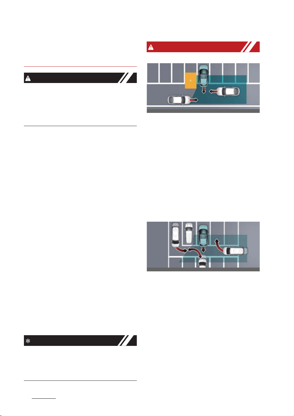
Driving your vehicle
1486
Rear Cross-Traffic Collision-Avoidance Assist (RCCA)
ple: open terrain), where any sub
-
stance are not detected after turning
ON the vehicle.
CAUTION
Turn off Rear Cross-Traffic Collision-
Avoidance Assist to install a trailer, car
-
rier, etc., or remove the trailer, carrier,
etc. to use Rear Cross-Traffic Collision-
Avoidance Assist.
Limitations of Rear Cross-Traffic
Collision-Avoidance Assist
Rear Cross-Traffic Collision-Avoidance
Assist may not operate normally, or the
function may operate unexpectedly
under the following circumstances:
僅 Departing from where trees or grass
are overgrown
僅Departing from where roads are wet
僅 Speed of the approaching vehicle is
fast or slow
Braking control may not work, driver's
attention is required in the following cir
-
cumstances:
僅 The vehicle severely vibrates while
driving over a bumpy road, uneven
road or concrete patch
僅 Driving on a slippery surface due to
snow, water puddle, ice, etc.
僅 The tire pressure is low or a tire is
damaged
僅 The brake is reworked
僅Remote Smart Parking Assist is oper
-
ating (if equipped)
NOTICE
For more details on the limitations of the
rear corner radar, refer to "Blind-Spot
Collision-Avoidance Assist (BCA) (if
equipped)" on page 6-67.
WARNING
僅 Driving near a vehicle or structure
[A]: Structure
Rear Cross-Traffic Collision-Avoid
-
ance Assist may be limited when driv
-
ing near a vehicle or structure, and
may not detect the vehicle approach
-
ing from the blind spot area. If this
occurs, the function may not warn the
driver or control the brakes when nec
-
essary.
Always check your surroundings while
Reversing.
僅 When the vehicle is in a complex
parking environment
Rear Cross-Traffic Collision-Avoid
-
ance Assist may detect vehicles which
are parking or pulling out near your
vehicle (for example: a vehicle leaving
beside your vehicle, a vehicle parking
or pulling out in the rear area, a vehi
-
cle approaching your vehicle making
a turn, etc.). If this occurs, the function
may unnecessarily warn the driver
and control the brake.
Always check your surroundings while
Reversing.
OCV051245L
OCV051246L
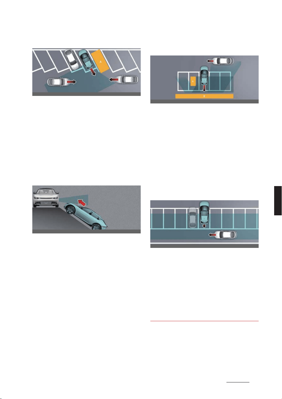
149
6
6
Driving your vehicle Rear Cross-Traffic Collision-Avoidance Assist (RCCA)
僅 When the vehicle is parked diagonally
[A]: Vehicle
Rear Cross-Traffic Collision-Avoid
-
ance Assist may be limited when
Reversing diagonally, and may not
detect the vehicle approaching from
the blind spot area. If this occurs, the
function may not warn the driver or
control the brakes when necessary.
Always check your surroundings while
Reversing.
僅 When the vehicle is on or near a slope
Rear Cross-Traffic Collision-Avoid
-
ance Assist may be limited when the
vehicle is on a uphill or downhill slope,
or near it, and may not detect the
vehicle approaching from the blind
spot area. If this occurs, the function
may not warn the driver or control the
brakes when necessary.
Always check your surroundings while
Reversing.
僅 Pulling into the parking space where
there is a structure
[A]: Structure, [B]: Wall
Rear Cross-Traffic Collision-Avoid
-
ance Assist may detect vehicles pass
-
ing by in front of you when parking
backwards into a parking space with a
wall or structure in the rear or side
area. If this occurs, the function may
unnecessarily warn the driver and
control the brake.
Always check your surroundings while
Reversing.
僅 When the vehicle is parked rearward
Rear Cross-Traffic Collision-Avoid
-
ance Assist may detect vehicles pass
-
ing by behind you when parking
backwards into a parking space. If this
occurs, the function may unnecessar
-
ily warn the driver and control the
brake.
Always check your surroundings while
Reversing.
OCV051247L
OCV051079L
OCV051080L
OCV051081L
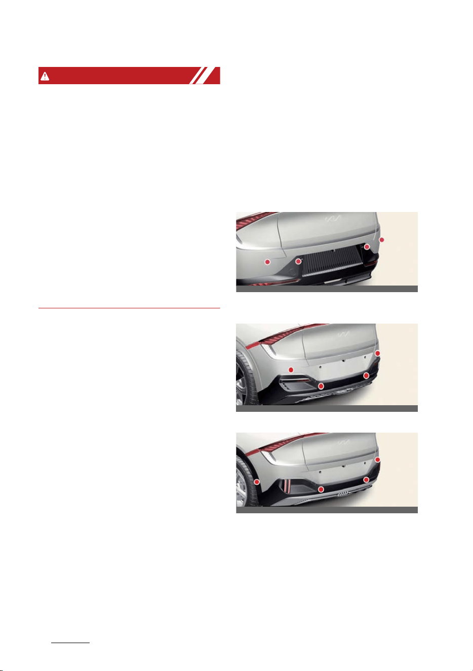
Driving your vehicle
1506
Reverse Parking Distance Warning (PDW)
WARNING
僅 When you are towing a trailer or
another vehicle, do not use Rear
Cross-Traffic Collision-Avoidance
Assist. The function could destabilize
the vehicle.
僅 Rear Cross-Traffic Collision-Avoid
-
ance Assist may not operate suddenly
if interfered by strong electromag
-
netic waves.
僅 Rear Cross-Traffic Collision-Avoid
-
ance Assist may not operate for 3 sec
-
onds after the vehicle is started, or the
rear corner radars are initialized.
僅 Reverse Parking Distance Warning
may not operate normally if the vehi
-
cle is turned off and restarted with the
front view camera covered.
Reverse Parking Distance
Warning (PDW) (if equipped)
Reverse Parking Distance Warning will
help warn the driver if a person, an ani
-
mal or an object is detected within a cer
-
tain distance when the vehicle is moving
in reverse.
Detecting sensor
Rear ultrasonic sensors (Type A)
Rear ultrasonic sensors (Type B - GT-
Line)
Rear ultrasonic sensors (Type C - GT)
Refer to the picture above for the
detailed location of the detecting sen
-
sors.
OCV041047L
OCV042645L
OCVGT042643L
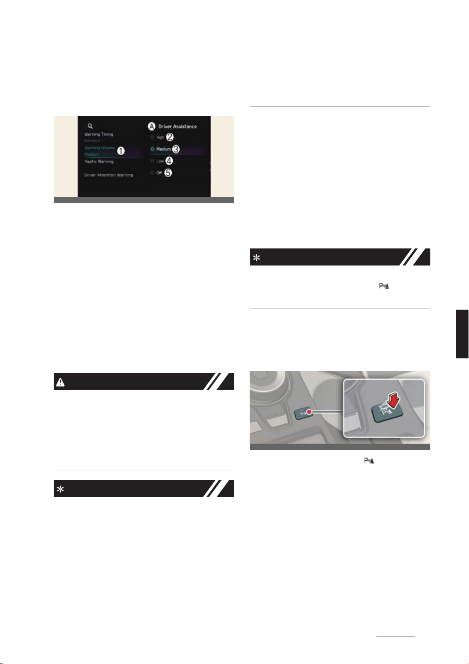
151
6
6
Driving your vehicle Reverse Parking Distance Warning (PDW)
Reverse Parking Distance Warn
-
ing settings
Warning volume
A:
Driver assistance
1 Warning volume
2 High
3 Medium
4 Low
5 Off
With the vehicle on,
Settings
→
Vehicle
→
Driver assistance
→
Warning vol
-
ume
on the infotainment system to
change the Warning volume to adjust
the Warning volume levels;
High
,
Medium
,
Low
or
Off
.
CAUTION
When the trailer is connected, Reverse
Parking Distance Warning Assist auto
-
matically turns off (if equipped). In this
case, you cannot get help from Reverse
Parking Distance Warning. Always drive
with care.
NOTICE
僅 If the vehicle is restarted, Warning vol
-
ume will maintain the last setting.
僅If
Off
is selected, the Warning volume
of Reverse Parking Distance Warning
will not turn off, but the volume will
sound as
Low
.
僅If
Off
is selected, steering wheel
vibration will not turn off.
僅 If you change the Warning volume,
the Warning volume of other Driver
Assistance systems may change.
Parking Distance Warning Auto
On
You can set the Parking Distance Waring
to be ON at low speeds. To use Parking
Distance Warning Auto On function,
select
Settings
→
Vehicle
→ 'Driver
Assistance' →
Parking safety
→
Park
-
ing Distance Warning Auto On
from
the infotainment system with the vehicle
ON.
NOTICE
If Parking Distance Warning Auto On is
selected, the Parking Safety ( ) button
indicator light will turn on.
Reverse Parking Distance Warn
-
ing operation
Parking Safety button
Press the Parking Safety ( ) button to
turn on or off Reverse Parking Distance
Warning.
僅 When Reverse Parking Distance
Warning is off (button indicator light
off), if you shift the gear to R
(Reverse), Reverse Parking Distance
Warning will automatically turn on.
僅 If you shift the gear to R (Reverse),
Reverse Parking Distance Warning
will not turn off even if you press the
OCV041562L
OCV041048L
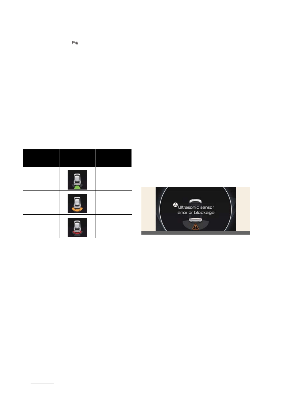
Driving your vehicle
1526
Reverse Parking Distance Warning (PDW)
Parking Safety ( ) button for your
safety.
Reverse Parking Distance Warn
-
ing
Reverse Parking Distance Warning will
operate under the following conditions.
僅 Shift the gear to R (Reverse).
僅 The vehicle's speed is below 10 km/h
(6 mph).
Function indications and warn
-
ings
僅 The corresponding indicator will illu
-
minate on the cluster or infotainment
system whenever each ultrasonic sen
-
sor detects a person, animal or object
in its sensing range. Also an audible
warning will sound.
僅 When more than two objects are
detected at the same time, the closest
one will be warned with an audible
warning.
僅 Distance from object may be detected
differently when obstacles are not
located in front of the sensor.
僅 The shape of the indicator in the illus
-
tration may differ from the actual
vehicle.
Reverse Parking Distance Warn
-
ing malfunction and precautions
Reverse Parking Distance Warn
-
ing malfunction
After starting the vehicle, a beep will
sound once when the gear is shifted to R
(Reverse) to indicate Reverse Parking
Distance Warning is operating normally.
However, if one or more of the following
occurs, first check whether the ultra
-
sonic sensor is damaged or blocked with
foreign material. If it still does not work
properly, Kia recommends visiting an
authorized Kia dealer/service partner.
僅 The audible warning does not sound.
僅 The buzzer sounds intermittently.
僅 The warning message appears on the
cluster.
A:
Ultrasonic sensor error or blockage
Limitations of Reverse Parking
Distance Warning
僅 Reverse Parking Distance Warning
may not operate normally when:
- Moisture is frozen to the sensor
(Reverse Parking Distance Warn
-
ing will operate normally when it is
melted.)
- Sensor is covered with foreign
material, such as snow or water
(Reverse Parking Distance Warn
-
ing will operate normally when
such foreign material are removed.)
- The weather is extremely hot or
cold
Distance from
object
Warning indicator
when driving back
-
ward
Warning sound
60~120 cm (24~48
inches)
Buzzer beeps inter
-
mittently
30~60 cm (12~24
inches)
Beeps more fre
-
quently
within 30 cm (12
inches)
Beeps continuously
OCV051191L

153
6
6
Driving your vehicle Reverse Parking Distance Warning (PDW)
- The sensor or sensor assembly is
disassembled
- The surface of the sensor is
pressed hard or an impact is
applied with a hard object
- The surface of the sensor is
scratched with a sharp object
- The sensors or its surrounding area
is directly sprayed with high pres
-
sure washer
僅 Reverse Parking Distance Warning
may malfunction when:
- Heavy rain or water spray is pres
-
ent
- Water flows on the surface of the
sensor
- Affected by another vehicle's sen
-
sors
- The sensor is covered with snow
- Driving on uneven road, gravel
roads or bushes
- Objects that generates ultrasonic
waves are near the sensor
- Installing the license plate differ
-
ently from the original location
- The vehicle bumper height or ultra
-
sonic sensor installation has been
modified
- Attaching equipments or accesso
-
ries around the ultrasonic sensors
僅 The following objects may not be
detected:
- Sharp or slim objects, such as
ropes, chains or small poles.
- Objects, which tend to absorb sen
-
sor frequency, such as clothes,
spongy material or snow.
- Objects smaller than 100 cm (40
inches) in length and narrower than
14 cm (6 inches) in diameter.
- Pedestrians, animals or objects that
are very close to the ultrasonic sen
-
sors
WARNING
僅 Reverse Parking Distance Warning is
a supplemental function. The opera
-
tion of Reverse Parking Distance
Warning can be affected by several
factors (including environmental con
-
ditions). It is the responsibility of the
driver to always check the rear view
before and while parking.
僅 Your vehicle warranty does not cover
any accidents or damage to the vehi
-
cle due to the malfunction of Reverse
Parking Distance Warning.
僅 Pay close attention when driving near
objects, pedestrians, and especially
children. Some objects may not be
detected by the ultrasonic sensors,
due to the objects distance, size or
material, all of which can limit the
effectiveness of the sensor.
僅 Parking Distance Warning indicator
may not occur sequentially depending
on vehicle speed or obstacle shape.
僅 If Forward/Reverse Parking Distance
Warning needs repair, Kia recom
-
mends visiting an authorized Kia
dealer/service partner.
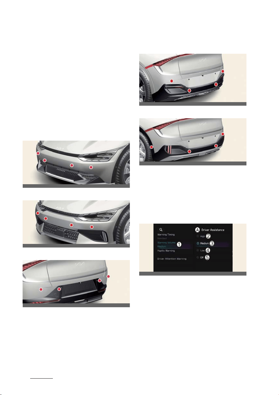
Driving your vehicle
1546
Forward/Reverse Parking Distance Warning (PDW)
Forward/Reverse Parking Dis
-
tance Warning (PDW) (if
equipped)
Forward/Reverse Parking Distance
Warning will help warn the driver if a
person, an animal or an object is
detected within a certain distance from
the ultrasonic sensors when the vehicle
is moving forward or in reverse.
Detecting sensor
Front ultrasonic sensors (Type A)
Front ultrasonic sensors (Type B)
Rear ultrasonic sensors (Type A)
Rear ultrasonic sensors (Type B - GT-
Line)
Rear ultrasonic sensors (Type C - GT)
Refer to the picture above for the
detailed location of the detecting sen
-
sors.
Forward/Reverse Parking Dis
-
tance Warning settings
Warning volume
A:
Driver assistance
1 Warning volume
2 High
3 Medium
4 Low
5 Off
With the vehicle on, touch
Settings
→
Driver Assistance
→
Warning Volume
on the instrument cluster or
Settings
→
Vehicle
→
Driver assistance
→
Warn
-
ing volume
on the infotainment system
OCV041049L
OCVGT042049L
OCV041047L
OCV042645L
OCVGT042643L
OCV041562L
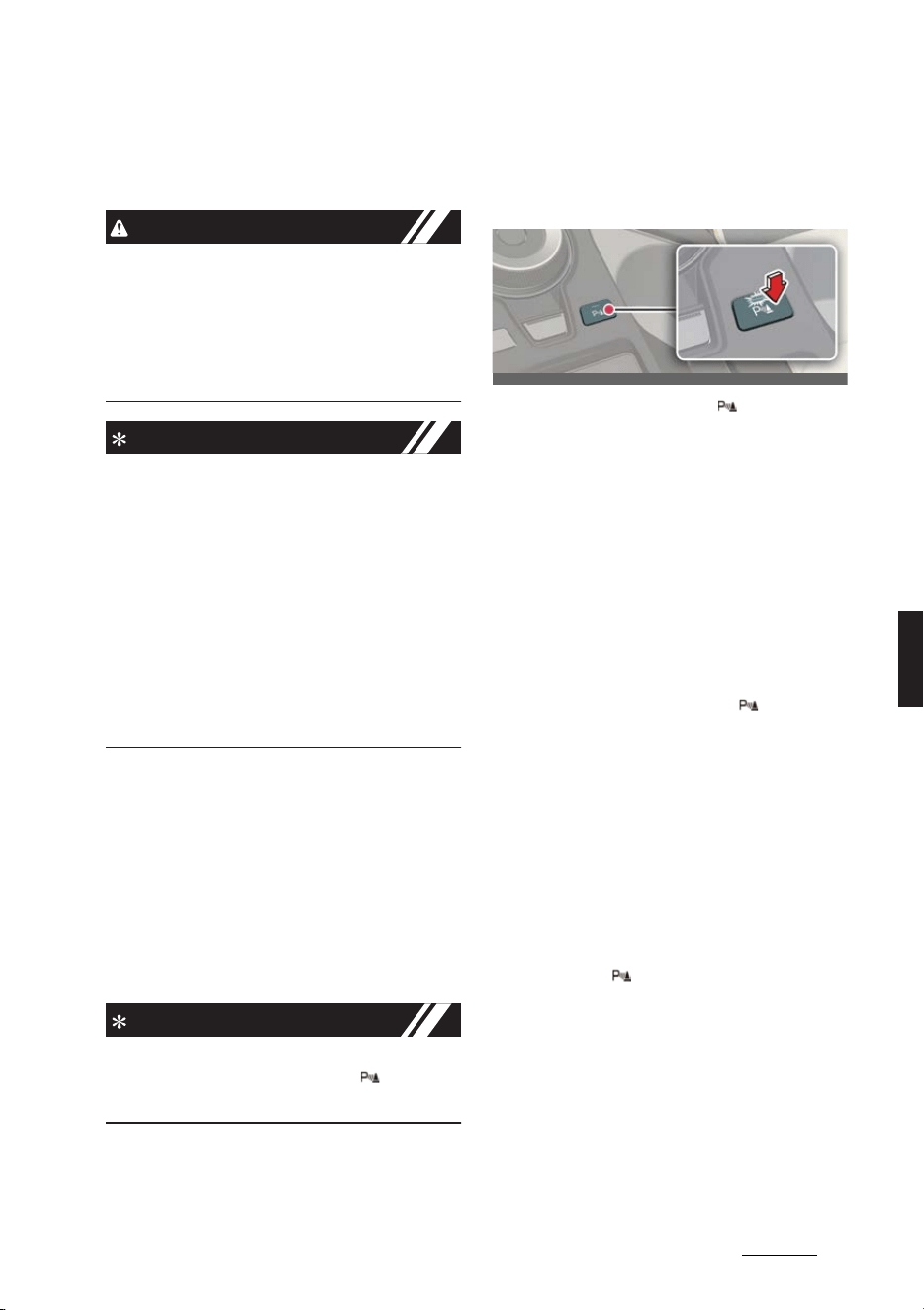
155
6
6
Driving your vehicle Forward/Reverse Parking Distance Warning (PDW)
to change the Warning volume to adjust
the Warning volume levels;
High
,
Medium
,
Low
or
Off
.
CAUTION
When the trailer is connected, Reverse
Parking Distance Warning Assist auto
-
matically turns off (if equipped). In this
case, you cannot get help from Reverse
Parking Distance Warning. Always drive
with care.
NOTICE
僅 If the vehicle is restarted, Warning vol
-
ume will maintain the last setting.
僅If
Off
is selected, the Warning volume
of Forward/Reverse Parking Distance
Warning will not turn off, but the vol
-
ume will sound as
Low
.
僅If
Off
is selected, steering wheel
vibration will not turn off.
僅 If you change the Warning volume,
the Warning volume of other Driver
Assistance systems may change.
Parking Distance Warning Auto
On
You can set the parking distance warn
-
ing to be ON at low speeds. To use Park
-
ing Distance Warning Auto On function,
select
Settings
→
Vehicle
→
Driver
assistance
→
Parking safety
→
Park
-
ing Distance Warning Auto On
from
the infotainment system screen.
NOTICE
If Parking Distance Warning Auto On is
selected, the Parking Safety ( ) button
indicator light will turn on.
Forward/Reverse Parking Dis
-
tance Warning operation
Parking Safety button
Press the Parking Safety ( ) button to
turn on or off Forward/Reverse Parking
Distance Warning.
僅 When Forward/Reverse Parking Dis
-
tance Warning is off (button indicator
light off), if you shift the gear to R
(Reverse), Forward/Reverse Parking
Distance Warning will automatically
turn on.
僅 If you shift the gear to R (Reverse),
Forward/Reverse Parking Distance
Warning will not turn off even if you
press the Parking Safety ( ) button
for your safety.
Forward Parking Distance Warn
-
ing
Forward Parking Distance Warning will
operate when one of the condition is sat
-
isfied.
僅 The gear is shifted from R (Reverse)
to D (Drive)
僅 The gear is in D (Drive) and the Park
-
ing Safety ( ) button indicator light is
on
僅
Parking Distance Warning Auto On
is selected from the Settings menu
and the gear is in D (Drive)
僅 The function warns the driver when
Settings
→
Vehicle
→ 'Driver Assis
-
tance' →
Parking safety
→
Parking
Distance Warning Auto On
is
OCV041048L
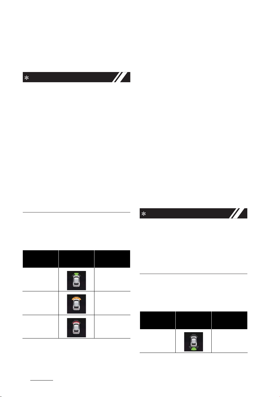
Driving your vehicle
1566
Forward/Reverse Parking Distance Warning (PDW)
selected from the infotainment sys
-
tem, and the gear is in D (Drive)
僅 Vehicle speed is below 10 km/h (6
mph)
NOTICE
僅 Forward Parking Distance Warning
does not operate when the vehicle's
forward speed is above 10 km/h (6
mph) even when the function is on
(Parking Safety button indicator is on).
Forward Parking Distance Warning
will operate again when the vehicle's
forward speed decreases below 10
km/h (6 mph).
僅 When the vehicle's forward speed is
above 30 km/h (18 mph), the Forward
Parking Distance Warning will turn off
(Parking Safety button indicator off).
Although you drive below 10 km/h (6
mph) again, Forward Parking Dis
-
tance Warning will not automatically
turn on.
Function indications and warn
-
ings
僅 The corresponding indicator will illu
-
minate on the cluster or infotainment
system screen whenever each ultra
-
sonic sensor detects a person, animal
or object in its sensing range. Also an
audible warning will sound.
僅 When more than two objects are
detected at the same time, the closest
one will be warned with an audible
warning.
僅 Distance from object may be detected
differently when obstacles are not
located in front of the sensor.
僅 The shape of the indicator in the illus
-
tration may differ from the actual
vehicle.
Reverse Parking Distance Warn
-
ing
Reverse Parking Distance Warning will
operate when one of the condition is sat
-
isfied.
僅 The gear is shifted to R (Reverse).
僅 The vehicle's rearward speed is below
10 km/h (6 mph).
NOTICE
When the vehicle's rearward speed is
below 10 km/h (6 mph), both the front
and rear ultrasonic sensors will detect
objects. However, the front ultrasonic
sensors can detect a person, animal or
object when it is within 60 cm (24
inches) from the sensors.
Function indications and warn
-
ings
Distance from
object
Warning indicator
when driving for
-
ward
Warning sound
60~100 cm (24~40
inches)
Buzzer beeps inter
-
mittently
30~60 cm (12~24
inches)
Beeps more fre
-
quently
within 30 cm (12
inches)
Beeps continuously
Distance from
object
Warning indicator
when driving back
-
ward
Warning sound
60~120 cm (24~48
inches)
Buzzer beeps inter
-
mittently

157
6
6
Driving your vehicle Forward/Reverse Parking Distance Warning (PDW)
僅 The corresponding indicator will illu
-
minate on the cluster or infotainment
system screen whenever each ultra
-
sonic sensor detects a person, animal
or object in its sensing range. Also an
audible warning will sound.
僅 When more than two objects are
detected at the same time, the closest
one will be warned with an audible
warning.
僅 Distance from object may be detected
differently when obstacles are not
located in front of the sensor.
僅 The shape of the indicator in the illus
-
tration may differ from the actual
vehicle.
Forward/Reverse Parking Dis
-
tance Warning malfunction and
precautions
Forward/Reverse Parking Dis
-
tance Warning malfunction
After starting the vehicle, a beep will
sound once when the gear is shifted to R
(Reverse) to indicate Forward/Reverse
Parking Distance Warning is operating
normally.
However, if one or more of the following
occurs, first check whether the ultra
-
sonic sensor is damaged or blocked with
foreign material. If it still does not work
properly, Kia recommends visiting an
authorized Kia dealer/service partner.
僅 The audible warning does not sound.
僅 The buzzer sounds intermittently.
僅 The warning message appears on the
cluster.
A:
Ultrasonic sensor error or blockage
Limitations of Forward/Reverse
Parking Distance Warning
僅 Forward/Reverse Parking Distance
Warning may not operate normally
when:
- Moisture is frozen to the sensor
(Forward/Reverse Parking Dis
-
tance Warning will operate nor
-
mally when it is melted.)
- Sensor is covered with foreign
material, such as snow or water
(Forward/Reverse Parking Dis
-
tance Warning will operate nor
-
mally when such foreign material
are removed.)
- The weather is extremely hot or
cold
- The sensor or sensor assembly is
disassembled
- The surface of the sensor is
pressed hard or an impact is
applied with a hard object
- The surface of the sensor is
scratched with a sharp object
- The sensors or its surrounding area
is directly sprayed with high pres
-
sure washer
僅 Forward/Reverse Parking Distance
Warning may malfunction when:
- Heavy rain or water spray is pres
-
ent
30~60 cm (12~24
inches)
Beeps more fre
-
quently
within 30 cm (12
inches)
Beeps continuously
Distance from
object
Warning indicator
when driving back
-
ward
Warning sound
OCV051193L

Driving your vehicle
1586
Forward/Reverse Parking Distance Warning (PDW)
- Water flows on the surface of the
sensor
- Affected by another vehicle's sen
-
sors
- The sensor is covered with snow
- Driving on uneven road, gravel
roads or bushes
- Objects that generates ultrasonic
waves are near the sensor
- Installing the license plate differ
-
ently from the original location
- The vehicle bumper height or ultra
-
sonic sensor installation has been
modified
- Attaching equipments or accesso
-
ries around the ultrasonic sensors
僅 The following objects may not be
detected:
- Sharp or slim objects, such as
ropes, chains or small poles.
- Objects, which tend to absorb sen
-
sor frequency, such as clothes,
spongy material or snow.
- Objects smaller than 100 cm (40
inches) in length and narrower than
14 cm (6 inches) in diameter.
- Pedestrians, animals or objects that
are very close to the ultrasonic sen
-
sors
WARNING
僅 Forward/Reverse Parking Distance
Warning is a supplemental function.
The operation of Forward/Reverse
Parking Distance Warning can be
affected by several factors (including
environmental conditions). It is the
responsibility of the driver to always
check the front and rear views before
and while parking.
僅 Your vehicle warranty does not cover
any accidents or damage to the vehi
-
cle due to the malfunction of For
-
ward/Reverse Parking Distance
Warning.
僅 Pay close attention when driving near
objects, pedestrians, and especially
children. Some objects may not be
detected by the ultrasonic sensors,
due to the objects distance, size or
material, all of which can limit the
effectiveness of the sensor.
僅 Parking Distance Warning indicator
may not occur sequentially depending
on vehicle speed or obstacle shape.
僅 If Forward/Reverse Parking Distance
Warning needs repair, Kia recom
-
mends visiting an authorized Kia
dealer/service partner.
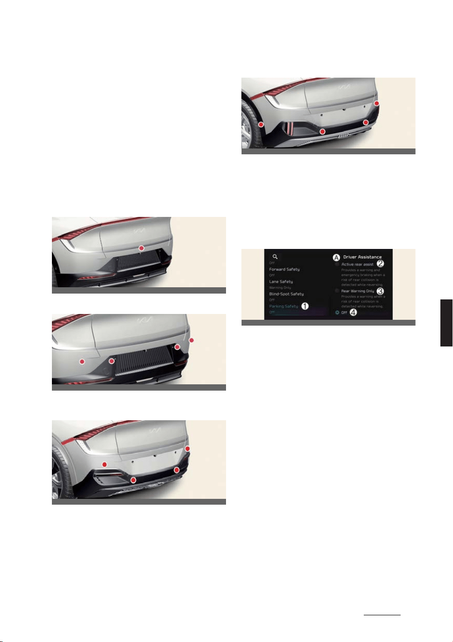
159
6
6
Driving your vehicle Reverse Parking Collision-Avoidance Assist (PCA)
Reverse Parking Collision-
Avoidance Assist (PCA) (if
equipped)
Reverse Parking Collision-Avoidance
Assist will can warn the driver or assist
with braking to help reduce the possibil
-
ity of collision with a pedestrian or an
object when Reversing.
Detecting sensor
Rear view camera
Rear ultrasonic sensors (Type A)
Rear ultrasonic sensors (Type B - GT-
Line)
Rear ultrasonic sensors (Type C - GT)
Refer to the picture above for the
detailed location of the detecting sen
-
sors.
Reverse Parking Collision- Avoid
-
ance Assist settings
Parking Safety
A:
Driver assistance
1 Parking safety
2 Rear Active Assist
3 Rear warning only
4 Off
With the vehicle on, select or deselect
Settings
→
Vehicle
→
Driver assis
-
tance
→
Parking safety
from the info
-
tainment system screen to set whether
or not to use each function.
僅
Rear Active Assist
: Reverse Parking
Collision-Avoidance Assist will warn
the driver and assist with braking
when a collision with a pedestrian or
an object is imminent.
僅
Rear Warning Only
: Reverse Parking
Collision-Avoidance Assist will warn
the driver when a collision with a
pedestrian or an object is imminent.
Braking will not be assisted.
OCVGT042642L
OCV041047L
OCV042645L
OCVGT042643L
OCV041586L
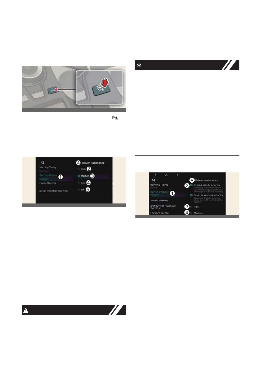
Driving your vehicle
1606
Reverse Parking Collision-Avoidance Assist (PCA)
僅
Off
: Reverse Parking Collision-Avoid
-
ance Assist will turn off.
Turning On/Off
Press and hold the Parking Safety ( )
button for more than 2 seconds to turn
Active rear assist or Rear Warning Only
on or off.
Warning volume
A:
Driver assistance
1 Warning volume
2 High
3 Medium
4 Low
5 Off
With the vehicle on, touch
Settings
→
Vehicle
→
Driver assistance
→
Warn
-
ing volume
on the infotainment system
to change the Warning volume to adjust
the Warning volume levels;
High
,
Medium
,
Low
or
Off
.
CAUTION
When the trailer is connected, Reverse
Parking Collision-Avoidance Assist auto
-
matically turns off (if equipped). In this
case, you cannot get help from Reverse
Parking Collision-Avoidance Assist.
Always drive with care.
NOTICE
僅 If the vehicle is restarted, Warning vol
-
ume will maintain the last setting.
僅If
Off
is selected, the Warning volume
of Reverse Parking Collision-Avoid
-
ance Assist will not turn off, but the
volume will sound as
Low
.
僅If
Off
is selected, steering wheel
vibration will not turn off.
僅 If you change the Warning volume,
the Warning volume of other Driver
Assistance systems may change.
Warning Volume
A:
Driver assistance
1 Warning volume
2 High
3 Medium
4 Low
5 Off
With the vehicle on, select
Settings
→
Vehicle
→
Driver assistance
→
Warn
-
ing volume
from the infotainment sys
-
tem screen to change the Warning
Volume to
High
,
Medium
,
Low
or
Off
for Reverse Parking Collision-Avoidance
Assist.
OCV041048L
OCV041562L
OCVGT042562L

161
6
6
Driving your vehicle Reverse Parking Collision-Avoidance Assist (PCA)
NOTICE
僅 If you change the Warning Volume,
the warning volume of other Driver
Assistance systems may change.
僅 However, even if
Off
is selected, the
volume will not turn off but the vol
-
ume will sound as
Low
.
Reverse Parking Collision- Avoid
-
ance Assist operation
Operating conditions
After selecting
Active assistance
or
Warning only
from the Settings menu,
Reverse Parking Collision-Avoidance
Assist will turn on when the following
conditions are satisfied:
僅 The tailgate is closed
僅 The gear is shifted to R (Reverse)
僅 Vehicle speed is below 10 km/h (6
mph)
僅 Reverse Parking Collision-Avoidance
Assist components such as the rear
view camera and the rear ultrasonic
sensors are in normal conditions
When Reverse Parking Collision- Avoid
-
ance Assist activates, a line appears
behind the vehicle image in the instru
-
ment cluster.
NOTICE
Reverse Parking Collision-Avoidance
Assist operates only once after the gear
is shifted to R (Reverse). To reactivate
Reverse Parking Collision-Avoidance
Assist, shift the gear from another gear
to R (Reverse).
Active rear assist
If Reverse Parking Collision-Avoidance
Assist detects a risk of collision with a
pedestrian or an object, Reverse Parking
Collision-Avoidance Assist will warn the
driver with an audible warning and
warning message on the cluster. When
Rear View Monitor is operating, a warn
-
ing will appear on the infotainment sys
-
tem screen. The warning will turn off
when the driver shifts the gear to P
(Park), N (Neutral), or D (Drive).
If Reverse Parking Collision-Avoidance
Assist detects an imminent collision with
a pedestrian or an object behind the
vehicle, Reverse Parking Collision-
Avoidance Assist will assist you with
braking. The driver needs to pay atten
-
tion as the brake assist will end within 5
minutes. Brake control will also end
when:
僅 The gear is shifted to P (Park) or D
(Drive).
僅 The driver depresses the brake pedal
with sufficient power.
NOTICE
If braking assist has lasted for approxi
-
mately 5 minutes, the Electronic Parking
Brake
EPB
will be engaged simultane
-
ously.
OCV051185L
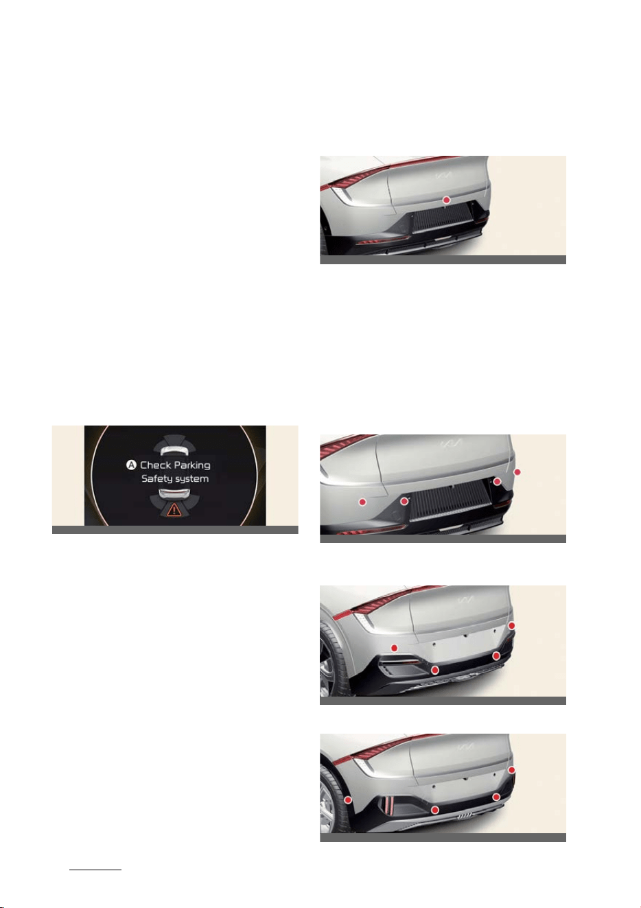
Driving your vehicle
1626
Reverse Parking Collision-Avoidance Assist (PCA)
Rear Warning Only
If Reverse Parking Collision-Avoidance
Assist detects a risk of collision with a
pedestrian or an object, Reverse Parking
Collision-Avoidance Assist will warn the
driver with an audible warning and
warning message on the cluster. When
Rear View Monitor is operating, a warn
-
ing will appear on the infotainment sys
-
tem screen. Braking will not be assisted.
The warning will turn off when the gear
is shifted to P (Park), N (Neutral) or D
(Drive).
Reverse Parking Collision- Avoid
-
ance Assist malfunction and lim
-
itations
Reverse Parking Collision- Avoid
-
ance Assist malfunction
A:
Check Parking Safety system
When Reverse Parking Collision- Avoid
-
ance Assist or other related functions
are not working properly, the warning
message will appear on the cluster, and
Reverse Parking Collision-Avoidance
Assist will turn off automatically.
Kia recommends visiting an authorized
Kia dealer/service partner.
Reverse Parking Collision-Avoid
-
ance Assist disabled
Rear view camera
The rear view camera is used as a
detecting sensor to detect pedestrians. If
the camera lens is covered with foreign
material, such as snow or rain, it may
adversely affect camera performance
and Reverse Parking Collision-Avoid
-
ance Assist may not operate normally.
Always keep the camera lens clean.
Rear ultrasonic sensors (Type A)
Rear ultrasonic sensors (Type B - GT-
Line)
Rear ultrasonic sensors (Type C - GT)
OCV051186L
OCVGT042642L
OCV041047L
OCV042645L
OCVGT042643L
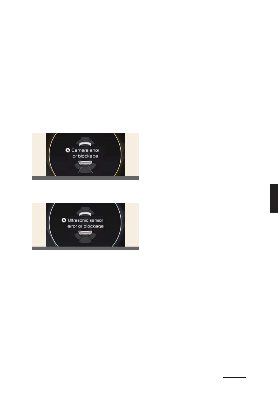
163
6
6
Driving your vehicle Reverse Parking Collision-Avoidance Assist (PCA)
The rear ultrasonic sensors are located
inside the rear bumper to detect objects
in the rear area. If the sensors are cov
-
ered with foreign material, such as snow
or rain, it may adversely affect sensor
performance and Reverse Parking Colli
-
sion-Avoidance Assist may not operate
normally. Always keep the rear bumper
clean.
The warning message will appear on the
cluster if the following situations occur:
Rear view camera
A:
Camera error or blockage
Rear ultrasonic sensors
A:
Ultrasonic sensor error or blockage
僅 The rear view camera or rear ultra
-
sonic sensor(s) is covered with foreign
material, such as snow or rain, etc.
僅 There is inclement weather, such as
heavy snow, heavy rain, etc.
If this occurs, Reverse Parking Collision-
Avoidance Assist may turn off or may
not operate properly. Check whether the
rear view camera and rear ultrasonic
sensors are clean.
Limitations of Reverse Parking
Collision-Avoidance Assist
Reverse Parking Collision-Avoidance
Assist may not assist braking or warn the
driver even if there are pedestrians or
objects under the following circum
-
stances:
僅 Any non-factory equipment or acces
-
sory is installed
僅 Your vehicle is unstable due to an
accident or other causes
僅 Bumper height or rear ultrasonic sen
-
sor installation has been modified
僅 Rear view camera or rear ultrasonic
sensor(s) is damaged
僅 Rear view camera or the rear ultra
-
sonic sensor(s) is stained with foreign
material, such as snow, dirt, etc.
僅 Rear view camera is obscured by a
light source or by inclement weather,
such as heavy rain, fog, snow, etc.
僅 The surrounding is very bright or very
dark
僅 Outside temperature is very high or
very low
僅 The wind is either strong (above 20
km/h (12 mph)) or blowing perpendic
-
ular to the rear bumper
僅 Objects generating excessive noise,
such as vehicle horns, loud motorcy
-
cle engines or truck air brakes, are
near your vehicle
僅 An ultrasonic sensor with similar fre
-
quency is near your vehicle
僅 The pedestrians are difficult to recog
-
nize under following conditions:
- There is ground height difference
between the vehicle and the pedes
-
trian
- The image of the pedestrian in the
rear view camera is indistinguish
-
able from the background
OCV051187L
OCV051188L

Driving your vehicle
1646
Reverse Parking Collision-Avoidance Assist (PCA)
- The pedestrian is near the rear
edge of the vehicle
- The pedestrian is not standing
upright
- The pedestrian is either very short
or very tall for Reverse Parking Col
-
lision- Avoidance Assist to detect
- The pedestrian or cyclist is wearing
clothing that easily blends into the
background, making it difficult to
detect
- The pedestrian is wearing clothing
that does not reflect ultrasonic
waves well
僅 Size, thickness, height, or shape of the
object does not reflect ultrasonic
waves well (e.g., pole, bush, curbs,
carts, edge of a wall, etc.)
僅 The pedestrian or the object is moving
僅 The pedestrian or the object is very
close to the rear of the vehicle
僅 A wall is behind the pedestrian or the
object
僅 The object is not located at the rear
center of your vehicle
僅 The object is not parallel to the rear
bumper
僅 The road is slippery or inclined
僅 The driver backs up the vehicle imme
-
diately after shifting to R (Reverse)
僅 The driver accelerates or circles the
vehicle
Reverse Parking Collision-Avoidance
Assist may unnecessarily warn the driver
or assist with braking even if there are
no pedestrians or objects under the fol
-
lowing circumstances:
僅 Any non-factory equipment or acces
-
sory is installed
僅 Your vehicle is unstable due to an
accident or other causes
僅 Bumper height or rear ultrasonic sen
-
sor installation has been modified
僅 Your vehicle height is low or high due
to heavy loads, abnormal tire pres
-
sure, etc.
僅 Rear view camera or the rear ultra
-
sonic sensor(s) is stained with foreign
material, such as snow, dirt, etc.
僅 The pattern on the road is mistaken
for a pedestrian
僅 There is shadow or light reflecting on
the ground
僅 Pedestrians or objects are around the
path of the vehicle
僅 Objects generating excessive noise,
such as vehicle horns, loud motorcy
-
cle engines or truck air brakes, are
near your vehicle
僅 Your vehicle is backing towards a nar
-
row passage or parking space
僅 Your vehicle is backing towards an
uneven road surface, such as an
unpaved road, gravel, bump, gradient,
etc.
僅 A trailer or carrier is installed on the
rear of your vehicle
僅 An ultrasonic sensor with similar fre
-
quency is near your vehicle
WARNING
僅 Always pay extreme caution while
driving. The driver is responsible for
controlling the brake for safe driving.
僅 Always pay attention to road and traf
-
fic conditions while driving, whether
or not there is a warning.
僅 Always look around your vehicle to
make sure there are no pedestrians or
objects before moving the vehicle.
僅 The performance of Reverse Parking
Collision-Avoidance Assist may vary
under certain conditions. If vehicle

165
6
6
Driving your vehicle Reverse Parking Collision-Avoidance Assist (PCA)
speed is above 4 km/h (2 mph),
Reverse Parking Collision- Avoidance
Assist will provide collision avoidance
assist only when pedestrians are
detected. Always look around and pay
attention when Reversing your vehi
-
cle.
僅 Some objects may not be detected by
the rear ultrasonic sensors due to the
objects distance, size or material, all of
which can limit the effectiveness of
the sensor.
僅 Reverse Parking Collision-Avoidance
Assist may not operate properly or
may operate unnecessarily depending
on the road conditions and the sur
-
roundings.
僅 Do not solely rely on Reverse Parking
Collision-Avoidance Assist. Doing so
may lead to vehicle damage or inju
-
ries.
僅 Always keep the rear view camera
and rear ultrasonic sensors clean.
僅 Do not use any cleanser containing
acid or alkaline detergents when
cleaning the rear view camera lens.
Use only a mild soap or neutral deter
-
gent, and rinse thoroughly with water.
僅 Do not spray the rear view camera or
the rear ultrasonic sensors or their
surrounding area directly with a high
pressure washer. It may cause the
rear view camera or the rear ultra
-
sonic sensors to malfunction.
僅 Do not apply objects, such as a
bumper sticker or a bumper guard,
near the rear view camera or rear
ultrasonic sensors or apply paint to
the bumper. Doing so may adversely
affect the performance of Reverse
Parking Collision-Avoidance Assist.
僅 Never disassemble or apply impact on
the rear view camera or the rear ultra
-
sonic sensors components.
僅 Do not apply unnecessary force on
the rear view camera or the rear ultra
-
sonic sensors. Reverse Parking Colli
-
sion-Avoidance Assist may not
operate properly if the rear view cam
-
era or the rear ultrasonic sensor(s) is
forcibly moved out of proper align
-
ment. Kia recommends visiting an
authorized Kia dealer/service partner.
僅 Noise may be heard when sudden
braking occurs to avoid a collision.
僅 If any other warning sound such as
the seat belt warning chime is already
generated, Reverse Parking Collision-
Avoidance Assist warning may not
sound.
僅 Reverse Parking Collision-Avoidance
Assist may not work properly if the
bumper has been damaged, replaced
or repaired.
僅 Reverse Parking Collision-Avoidance
Assist may not operate normally if
interfered by strong electromagnetic
waves.
僅 Playing the vehicle audio system at
high volume may prevent passengers
from hearing Reverse Parking Colli
-
sion-Avoidance Assist warning
sounds.
僅 The brake control may not operate
properly depending on the status of
ESC (Electronic Stability Control).
There will only be a warning when:
- The ESC (Electronic Stability Con
-
trol) warning light is on
- ESC (Electronic Stability Control) is
engaged in a different function
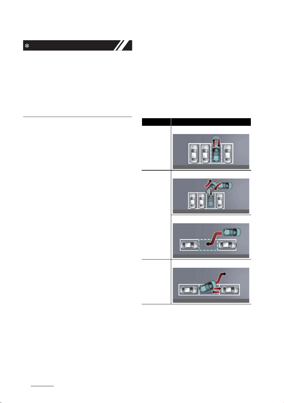
Driving your vehicle
1666
Remote Smart Parking Assist (RSPA)
NOTICE
Reverse Parking Collision-Avoidance
Assist can detect a pedestrian or an
object when:
僅 A pedestrian is standing behind the
vehicle
僅 A large obstacle, such as a vehicle, is
parked in the rear center of your vehi
-
cle
Remote Smart Parking Assist
(RSPA) (if equipped)
Remote Smart Parking Assist uses vehi
-
cle sensors to help the driver park and
exit parking spaces remotely from out
-
side the vehicle by automatically search
-
ing for parking spaces, and controlling
the steering wheel, vehicle speed and
gearshifts.
僅 Remote Smart Parking and Remote
Operation function may be operated
from outside the vehicle using the
smart key.
僅 Smart Parking and Remote Smart
Parking function may be operated
from inside the vehicle.
Function Description
Remote Opera
-
tion
Remotely moving forward or backward
Smart Parking
or Remote
Smart Parking
Perpendicular reverse parking
Parallel reverse parking
Smart Exit
Parallel forward exit
OCV051082L
OCV051083L
OCV051084L
OCV051085L
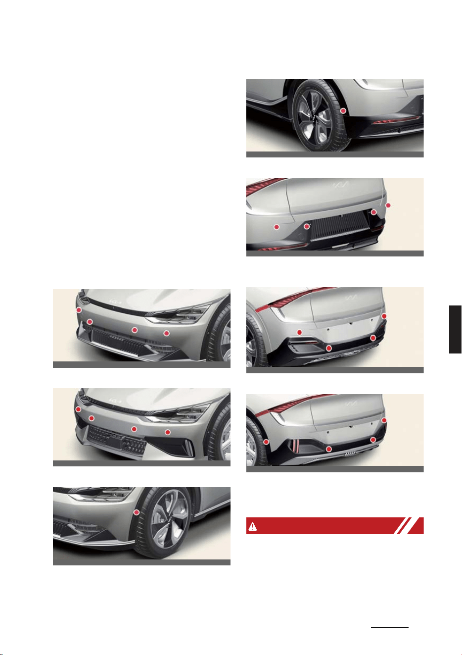
167
6
6
Driving your vehicle Remote Smart Parking Assist (RSPA)
僅 Smart Parking and Remote Smart
Parking function helps the driver with
perpendicular reverse parking and
parallel reverse parking.
僅 Smart Exit function helps the driver
with parallel forward exit.
僅 When Remote Smart Parking Assist
operates, Parking Distance Warning
and Surround View Monitor will also
operate. For more details, refer to
"Forward/Reverse Parking Distance
Warning (PDW) (if equipped)" on page
6-154 and "Surround View Monitor
(SVM) (if equipped)" on page 6-138.
Detecting sensor
Front ultrasonic sensors (Type A)
Front ultrasonic sensors (Type B)
Front side ultrasonic sensors
Rear side ultrasonic sensors
Rear ultrasonic sensors (Type A)
Rear ultrasonic sensors (Type B - GT-
Line)
Rear ultrasonic sensors (Type C - GT)
Refer to the picture above for the
detailed location of the detecting sen
-
sors.
WARNING
僅 Never disassemble the detecting sen
-
sor or sensor assembly, or apply any
impact on it.
僅If the detecting sensor have been
replaced or repaired, we recommend
OCV041049L
OCVGT042049L
OCV051086L
OCV051087L
OCV041047L
OCV042645L
OCVGT042643L
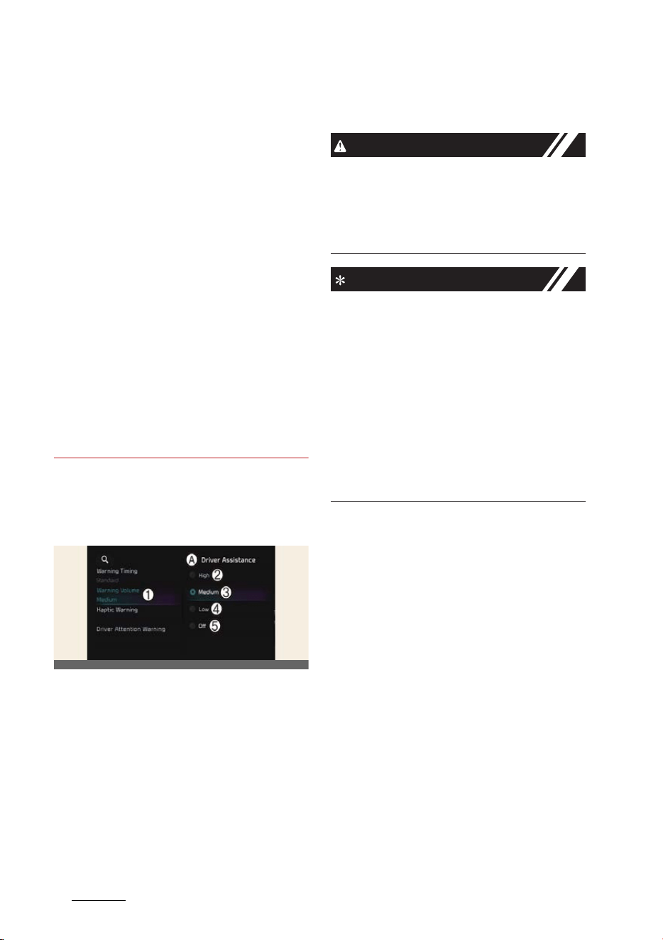
Driving your vehicle
1686
Remote Smart Parking Assist (RSPA)
that you have your vehicle inspected
by an authorized Kia dealer/service
partner.
僅Remote Smart Parking Assist may
malfunction if the vehicle bumper
height or ultrasonic sensor installation
has been modified or damaged. Any
non-factory installed equipment or
accessories may also interfere with
the sensor performance.
僅 When the ultrasonic sensor is frozen
or stained with snow, dirt, or water,
the sensor may not operate until the
stains are removed using a soft cloth.
僅 Do not push, scratch or strike the
ultrasonic sensor. Sensor damage
could occur.
僅 Do not spray the ultrasonic sensors or
its surrounding area directly with a
high pressure washer.
Remote Smart Parking Assist set
-
tings
Warning volume
A:
Driver assistance
1 Warning volume
2 High
3 Medium
4 Low
5 Off
With the vehicle on, touch
Settings
→
Vehicle
→
Driver assistance
→
Warn
-
ing volume
on the infotainment system
to change the Warning volume to adjust
the Warning volume levels;
High
,
Medium
,
Low
or
Off
.
CAUTION
When the trailer is connected, Remote
Smart Parking Assist automatically turns
off (if equipped). In this case, you cannot
get help from Remote Smart Parking
Assist. Always drive with care.
NOTICE
僅 If the vehicle is restarted, Warning vol
-
ume will maintain the last setting.
僅If
Off
is selected, the Warning volume
of Remote Smart Parking Assist will
not turn off, but the volume will sound
as
Low
.
僅If
Off
is selected, steering wheel
vibration will not turn off.
僅 If you change the Warning volume,
the Warning volume of other Driver
Assistance systems may change.
OCV041562L
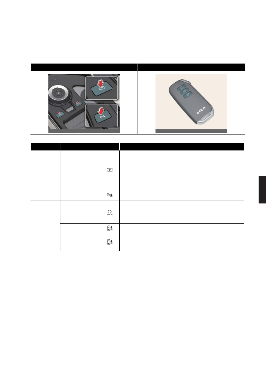
169
6
6
Driving your vehicle Remote Smart Parking Assist (RSPA)
Remote Smart Parking Assist operation
Remote Smart Parking button
Parking/View button, Parking Safety button Smart key
Location Name Symbol Description
Inside vehicle
Parking/View button
僅 Press and hold the Parking/View button to turn on Remote Smart Park
-
ing Assist. Also, Forward/Reverse Parking Distance warning will auto
-
matically turn on.
(However, functions may differ depending on the situations. Refer to
each function's description for more details in the following pages.)
僅 Press and hold the Parking/View button while Smart Parking or Smart
Exit function is on to operate the function.
Parking Safety button
僅 Press the Parking Safety button while Remote Smart Parking Assist is
operating to end function operation.
Smart key
Remote Start button
僅 Press the Remote Start button after the door is locked with the vehicle
off to start the vehicle remotely.
僅 Press the Remote Start button while Remote Operation function is oper
-
ating to end function operation.
Forward button
僅 When using Remote Smart Parking function, regardless of which direc
-
tion button is pressed, reverse parking is supported while the button is
pressed.
僅 When using the Remote Operation function, the vehicle moves in the
direction of the button while the button is pressed.
Backward button
OCV051088L_2
OGL3051095
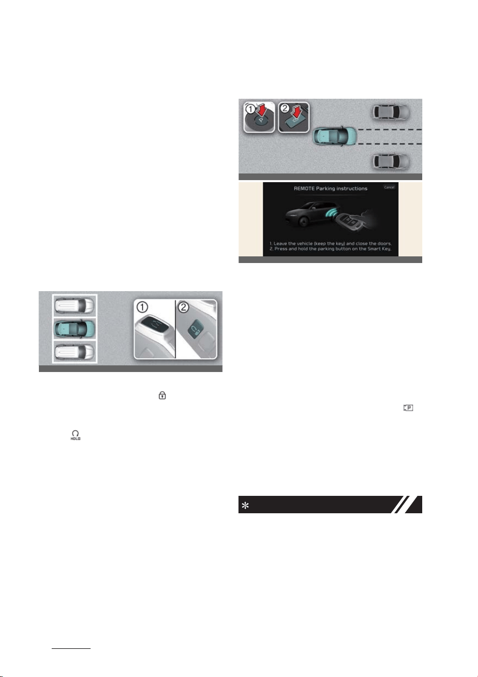
Driving your vehicle
1706
Remote Smart Parking Assist (RSPA)
Remote Operation
Operating order
Remote Operation operates in the fol
-
lowing order:
1. Getting ready to remotely move for
-
ward and backward
2. Remotely moving forward and back
-
ward
1. Getting ready to remotely
move forward and backward
There are two ways to operate Remote
Operation function.
Method (1): Using the function
with vehicle off
1. Within a certain range from the vehi
-
cle press the door lock ( ) button on
the smart key and lock all doors.
2. Press and hold the Remote Start but
-
ton ( ) within 4 seconds until the
vehicle starts.
* For more details on remotely starting
the vehicle, refer to "Locking/unlock
-
ing/remote starting/remote parking
with the smart key" on page 5-6.
Method (2): Using the function
with vehicle on
A:
REMOTELY moving forward/back
-
ward...
1 Leave the vehicle (keep the key)
and close the doors.
2 Press and hold the parking button
on the Smart Key.
1. Park the vehicle in front of the space
where you want to use Remote Oper
-
ation function, and shift the gear to P
(Park).
2. Press and hold the Parking/View ( )
button to turn on Smart Parking
Assist. A message
Under REMOTE
control
will appear on the infotain
-
ment system screen.
3. Get out of the vehicle with the smart
key and close all doors.
NOTICE
僅
Agree
must be selected on the info
-
tainment system screen and the info
-
tainment system has to operate
properly to use Remote Operation
function.
僅 Method (2) can be used after the vehi
-
cle has been driven above 5 km/h (3
mph).
OCV051089L_2
OCV051090L_2
OCVGT042184L
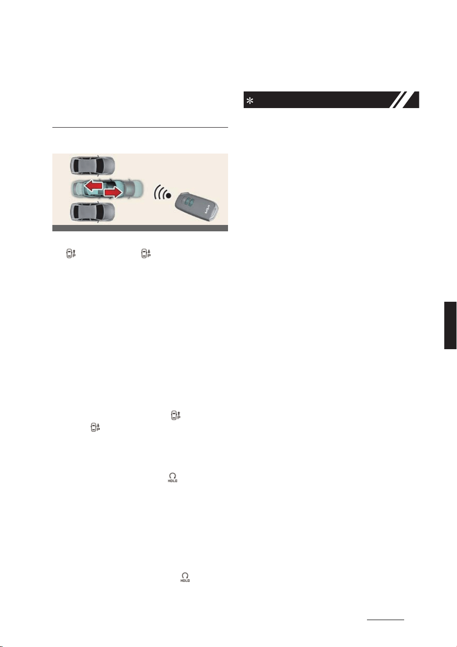
171
6
6
Driving your vehicle Remote Smart Parking Assist (RSPA)
僅 If the function is turned on again after
parallel parking is completed by
Remote Smart Parking Assist, Remote
Operation function can be used with
Method (2).
2. Remote Operation
1. Press and hold one of the Forward
( ) or Backward ( ) button on the
smart key.
僅 Remote Smart Parking Assist will
automatically control the steering
wheel, vehicle speed and gear shift.
The vehicle will move in the direc
-
tion of the button pressed.
僅 While Remote Operation function is
operating, if the you let the button,
the vehicle will stop and function
control will pause. The function will
start operating again when the but
-
ton is pressed and held again.
2. Hold down the Forward ( ) or Back
-
ward ( ) button until the vehicle
reaches the target location.
3. When Remote Operation is done, get
in the vehicle with the smart key or
press the Remote Start ( ) button on
the smart key from outside the vehi
-
cle.
僅 The message will appear on the
infotainment system screen. The
vehicle will automatically shift to P
(Park) and engage the parking
brake.
僅 When the Remote Start ( ) button
is pressed, the vehicle will turn off.
If the driver is in the vehicle, the
vehicle will retain ON position.
NOTICE
僅 Remote Operation can control the
vehicle remotely using the smart key
outside the vehicle.
僅 Check that all smart keys are outside
the vehicle when using Remote Oper
-
ation function.
僅 Remote Operation function will oper
-
ate only when the smart key is within
4 m (13 ft.) from the vehicle. If there is
no vehicle movement even when the
Forward or Backward button is
pressed on the smart key, check the
distance to the vehicle and press the
button again.
僅 The detecting range of the smart key
may vary depending on the surround
-
ings that are affected by radio waves
such as transmission tower, broadcast
station, etc.
僅 When remotely moving forward using
method (1), it is recognized as an exit
situation, and the vehicle moves 4 m
(13 ft.) to check for pedestrians, ani
-
mals or objects around the vehicle.
After confirmation, the steering wheel
is controlled according to the condi
-
tion ahead.
僅 When remotely moving forward using
method (2), it is recognized as a park
-
ing situation, and will immediately
control the steering wheel according
to the condition ahead to assist with
entering the parking space and align
-
ing the vehicle. However, perfor
-
mance may reduce depending on the
pedestrians, animals, shape of
objects, location, etc. around the vehi
-
cle.
僅 For moving remotely backward, both
method (1) and (2) aligns the steering
OCV051091L
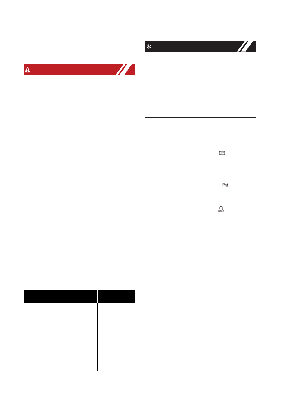
Driving your vehicle
1726
Remote Smart Parking Assist (RSPA)
wheel first, and then will only move
the vehicle straight.
WARNING
僅 When using Remote Operation func
-
tion, make sure that all passengers
have gotten out of the vehicle.
僅 Before leaving the vehicle, close win
-
dows and sunroofs, and make sure
the vehicle is off before locking the
doors.
僅 If the vehicle's battery is discharged or
Remote Smart Parking Assist mal
-
functions when parked in a narrow
parking space, Remote Operation
function will not operate. Always park
your vehicle in a space wide enough
for you to get in or out of your vehicle.
僅 Please note that depending on the
parking space, you may not be able to
exit from the space you have entered
by using Remote Operation function.
僅 After parking, the surrounding may
change due to the movement of sur
-
rounding vehicles. If this occurs,
Remote Operation function may not
operate.
Remote Smart Parking Assist
operation status
NOTICE
僅 Operation status by the hazard warn
-
ing light may not be applicable based
on the regulation of your country.
僅 If the smart key is not within the oper
-
ating range from the vehicle (approxi
-
mately 4 m (13 ft.)), the smart key LED
will not illuminate or blink. Use the
smart key within the operating range.
How to turn off Remote Opera
-
tion function while operating
僅 Press the Parking/View ( ) button or
shift the gear except to P (Park) while
the infotainment system screen
guides the driver using method 2.
僅 Press the Parking Safety ( ) button
or select
Cancel
on the infotainment
system screen.
僅 Press the Remote Start ( ) button on
the smart key while the vehicle is
being controlled by Remote Operation
function. Remote Operation function
will turn off. At this time, the vehicle
will turn off.
僅 Get on the vehicle with the smart key.
Remote Operation function will turn
off. At this time, the vehicle will remain
on.
The function will pause in the fol
-
lowing conditions when:
When Remote Operation function is
paused, the vehicle will stop. If the con
-
dition that made the function to pause
disappears, the function may operate
again.
僅 There is a pedestrian, animal or object
in the direction the vehicle is moving
僅 The door or tailgate is open
Operation Status Smart key LED
Hazard warning
light
Under control
Green LED Contin
-
uously blinks
-
Pause
Red LED Continu
-
ously blinks
Blinks
Off
Red LED illuminates
for 4 seconds and
then turns off
Blinks 3 times and
turns off
Complete
Green LED illumi
-
nates for 4 sec
-
onds and then
turns off
Blinks 1 time and
turns off

173
6
6
Driving your vehicle Remote Smart Parking Assist (RSPA)
僅 The Forward ( ) or Backward ( )
button is not continuously pressed
僅 Simultaneously pressing multiple but
-
tons on a smart key
僅 The smart key is not operated within 4
m (13 ft.) from the vehicle
僅 Button of another smart key is
pressed in addition to the operating
smart key (Excluding start button)
僅 Blind-Spot Collision-Avoidance Assist
or Rear Cross-Traffic Collision-Avoid
-
ance Assist operates while the vehicle
is being controlled in the reverse
direction.
僅 The vehicle moves 7 m (22 ft.) while
the smart key is pressed with Remote
Operation function (maximum travel
distance per button press)
The function will cancel in the fol
-
lowing conditions when:
When Remote Operation function is can
-
celed, the vehicle will automatically stop,
shift the gear to P (Park) and engage
EPB (Electronic Parking Brake).
僅 The steering wheel is steered
僅 The gear is shifted while the vehicle is
moving
僅 Operating EPB while the vehicle is
moving
僅 The vehicle hood is open
僅 The brake pedal or accelerator pedal
is depressed when all the doors are
closed
僅 The smart key is outside the vehicle
when the brake pedal is depressed
while the driver's door is open
僅 Rapid acceleration occurs
僅 Vehicle skid occurs
僅 The wheel is stuck by an obstacle and
cannot move
僅 Approximately 3 minutes and 50 sec
-
onds have past after Remote Opera
-
tion function has started to operate
僅 The slope of the road exceeds the
operational range
僅 The function is paused for more than
1 minute
僅 The total travel distance of the vehicle
has exceeded 14 m (45 ft.) after
Remote Operation function operation
僅 The steering wheel, gearshift, braking,
and drive controls are not working
normally
僅 There is a problem with the smart key
or the smart key battery is low
僅 ABS, TCS or ESC system operates due
to slippery road conditions
僅 The alarm of the Theft Alarm System
sounds
僅 The charging door opens
Smart Parking, Remote Smart
Parking
Operating order
Parking function operates in the follow
-
ing order:
1. Getting ready for parking
2. Searching for parking space
3. Select parking type and operating
mode
4. Smart Parking
5. Remote Smart Parking
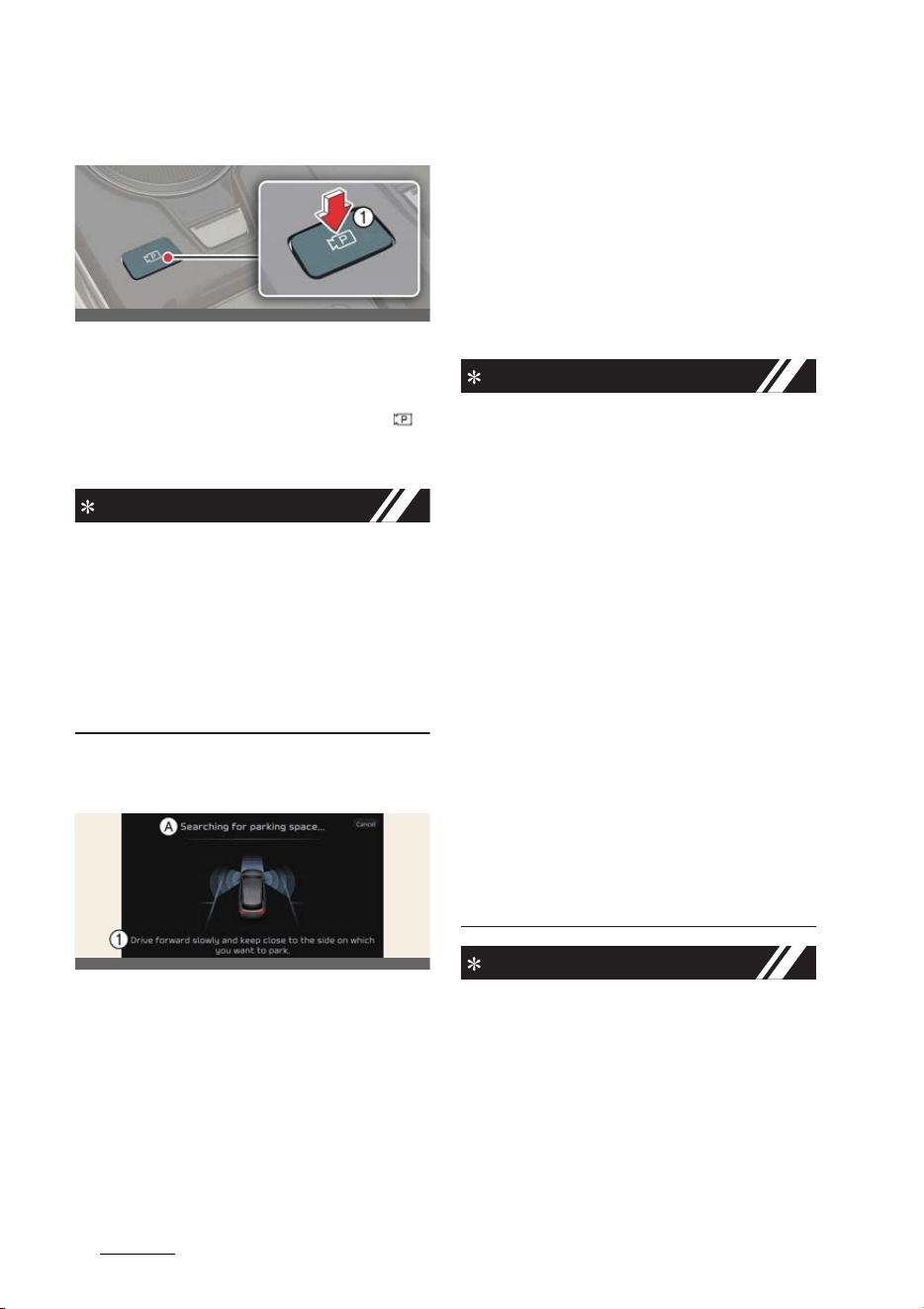
Driving your vehicle
1746
Remote Smart Parking Assist (RSPA)
1. Getting ready for parking
1. With the vehicle turned on, depress
the brake pedal and shift the gear to
D (Drive) or N (Neutral).
2. Press and hold the Parking/View ( )
button to turn on Remote Smart Park
-
ing Assist.
NOTICE
僅
Agree
must be selected on the info
-
tainment system screen and the info
-
tainment system has to operate
properly to use Parking function.
僅 If you drive above 5 km/h (3 mph)
with the vehicle on, you may use the
Parking function with the gear shifted
to N (Neutral).
2. Searching for parking space
A:
Searching for parking space...
1 Drive forward slowly and keep
close to the side on which you want
to park.
Slowly drive forward maintaining the
distance of approximately 100 cm (40
inches) from the parked vehicles. The
vehicle will search for a parking space
from the side or front/rear of parked
vehicle.
When searching for a parking space is
complete, a message will appear on the
infotainment system screen.
Select
parking type
will be displayed and the
selected parking space will appear on
Top View screen of Surround View Mon
-
itor.
NOTICE
僅 Remote Smart Parking Assist
searches for parking spaces that are
next to parked vehicles, or parking
spaces with parked vehicles in front or
rear.
僅 While searching for a parking space,
when vehicle speed is above 20 km/h
(12 mph), a message will appear on
the infotainment system screen
informing you to slow down. When
vehicle speed is above 30 km/h (18
mph), Parking function will turn off.
僅 Searching for a parking space will be
completed when there is enough
space to move the vehicle in addition
to the parking space.
僅 Even if an audible sound is heard to
notify that searching for a parking
space is complete, search completion
can be canceled immediately depend
-
ing on surroundings.
NOTICE
僅 If the distance is below 50 cm (20
inches) or over 150 cm (59 inches),
Remote Smart Parking Assist may not
be able to search for a parking space.
OCV051092L
OCVGT042152L
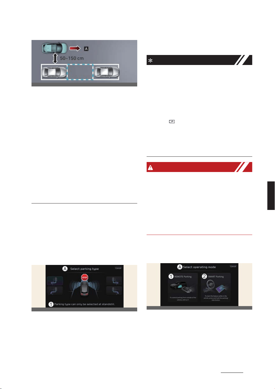
175
6
6
Driving your vehicle Remote Smart Parking Assist (RSPA)
[A]: Searching for parking space
僅 If you do not maintain a certain dis
-
tance from the parked vehicle, the
performance to search for a parking
space may reduce.
僅 Even if a diagonal parking space is
searched as a parking space, parking
is not assisted normally.
僅 Due to abnormal performance of the
ultrasonic sensor or the influence of
the surroundings, Parking function
may not be able to search for a park
-
ing space even if there is a parking
space, or may search for a space that
is not suitable for parking.
3. Select parking type and oper
-
ating mode
1. Parking type – Perpendicular
reverse (Left/Right), Parallel
reverse (Left/Right)
A:
Select parking type
1 Parking type can only be selected at
standstill.
With the vehicle stopped by depressing
the brake pedal, touch the infotainment
system screen to select the desired
parking type.
NOTICE
僅 If you continue to drive without stop
-
ping after the parking type selection
screen appears, Remote Smart Park
-
ing Assist will return to the previous
stage and search for a parking space.
僅 If Parking function is canceled unin
-
tentionally by pressing the Parking/
View ( ) button before the parking
type is selected, you can return to the
parking type selection stage by press
-
ing and holding the button again
while the vehicle is stopped.
WARNING
Before selecting the Parking type, the
driver should check whether the parking
space is suitable.
If the searched parking space by
Remote Smart Parking Assist is narrow
or unsuitable for parking, do not select
the Parking type and move the vehicle
to search for another parking space.
2. Operating mode – Remote
Parking, Smart Parking
A:
Select operating mode
1 REMOTE Parking
2 SMART Parking
After selecting a parking type, the info
-
tainment system screen will guide you
with Remote Smart Parking function and
OCV051093L
OCVGT042153L
OCVGT042154L
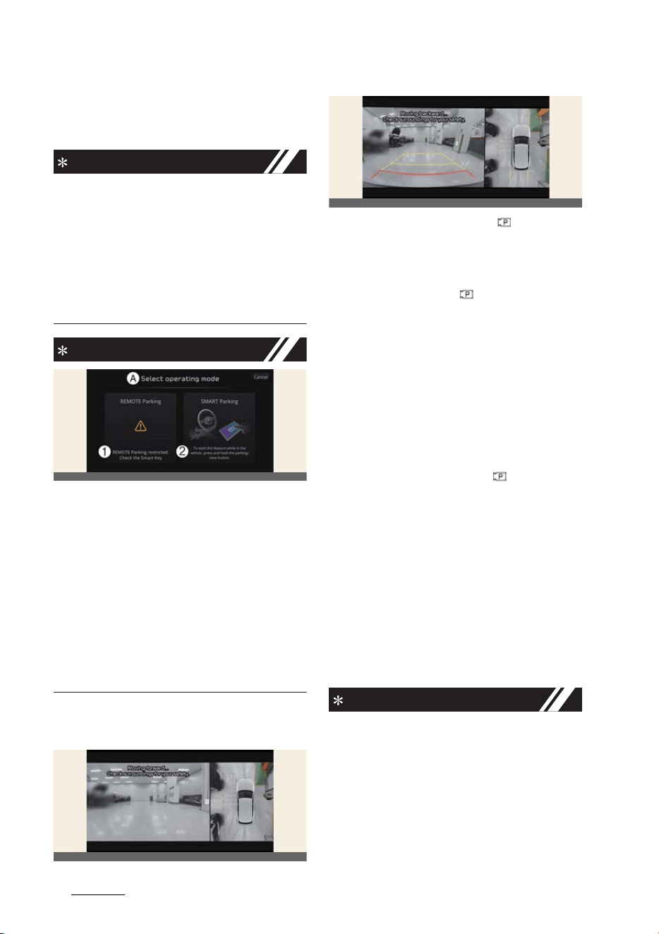
Driving your vehicle
1766
Remote Smart Parking Assist (RSPA)
Smart Parking function. Follow the
instructions to operate Remote Smart
Parking Assist.
NOTICE
僅 Operating instructions will be dis
-
played on the screen for each desired
function you select.
僅 Do not take your foot off the brake
pedal during the Parking function
guide. When the vehicle moves,
Remote Smart Parking Assist will turn
off.
NOTICE
A:
Select operating mode
1 REMOTE Parking restricted. Check
the Smart Key
2 To start this feature while in the
vehicle, press and hold the parking/
view button.
If Remote Smart Parking Assist cannot
activate Remote Smart Parking function,
only the Smart Parking guide will be dis
-
played on the infotainment system
screen.
4. Smart Parking
1. Press the Parking/View ( ) button
when the vehicle is stopped by
depressing the brake pedal.
2. Release the brake pedal while holding
the Parking/View ( ) button.
僅 Remote Smart Parking Assist will
automatically control the steering
wheel, vehicle speed and gear shift.
僅 If you do not hold down the Park
-
ing/View button, the vehicle will
stop and function control will
pause. The function will start oper
-
ating again when the Parking/View
button is pressed and held again.
3. Hold the Parking/View ( ) button
until the vehicle reaches the target
parking position.
僅 Message will appear on the info
-
tainment system screen to inform
you that parking is complete. The
vehicle will automatically shift to P
(Park) and engage the parking
brake.
4. If you need to change the vehicle's
position or location, manually com
-
plete parking your vehicle.
NOTICE
僅 Smart Parking function will not oper
-
ate if the door is open or the seat belt
is not fastened.
僅 The parking location indicator is dis
-
played on Surround View Monitor
screen and is displayed until the vehi
-
cle enters the parking space for the
first time by Smart Parking function.
OCVGT042197L
OCV041198L
OCV041199L
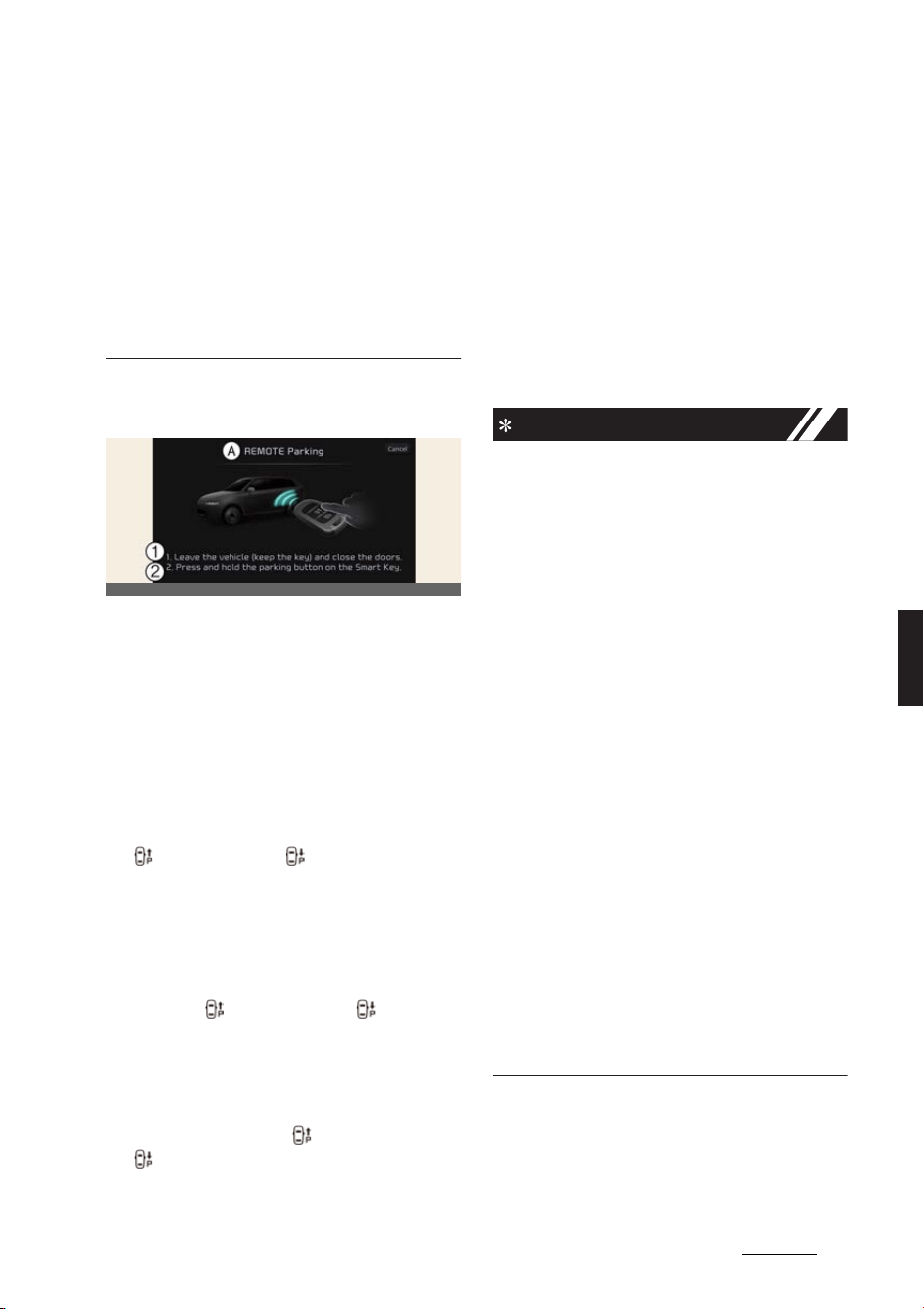
177
6
6
Driving your vehicle Remote Smart Parking Assist (RSPA)
僅 Vehicle speed can be adjusted by
depressing the brake pedal while
Smart Parking function is operating.
However, the vehicle does not accel
-
erate even when the accelerator pedal
is depressed.
僅 Depending on parking environments,
if the vehicle is stopped by a stopper,
parking may be completed.
5. Remote Smart Parking
A:
REMOTE Parking
1 Leave the vehicle (keep the key)
and close the doors.
2 Press and hold the parking button
on the Smart Key.
1. Shift the gear to P (Park).
2. Get out of the vehicle with the smart
key, and close all doors.
3. Press and hold one of the Forward
( ) or Backward ( ) button on the
smart key.
僅 Remote Smart Parking Assist will
automatically control the steering
wheel, vehicle speed and gear shift.
僅 If you do not hold down the For
-
ward ( ) or Backward ( ) button,
the vehicle will stop and function
control will pause. The function will
start operating again when the but
-
ton is pressed and held again.
4. Hold the Forward ( ) or Backward
( ) button on the smart key until the
parking is complete.
僅 When the vehicle reaches the tar
-
get parking position, a message will
appear on the infotainment system
screen to inform you that parking is
complete. The vehicle will automati
-
cally shift to P (Park), engage EPB
(Electronic Parking Brake) and the
vehicle will turn off.
5. If you need to change the vehicle's
position or location, manually com
-
plete parking your vehicle.
NOTICE
僅 When operating Remote Smart Park
-
ing function, make sure all smart keys
are outside of the vehicle.
僅 Remote Smart Parking function will
operate only when the smart key is
within 4 m (13 ft.) from the vehicle. If
there is no vehicle movement even
when the Remote Forward or Back
-
ward button is pressed on the smart
key, check the distance to the vehicle
and press the button again.
僅 The detecting range of the smart key
may vary depending on the surround
-
ings that are affected by radio waves
such as transmission tower, broadcast
station, etc.
僅 The parking location indicator is dis
-
played on Surround View Monitor
screen and is displayed until the vehi
-
cle enters the parking space for the
first time by Remote Smart Parking
function.
僅 Depending on parking environments,
if the vehicle is stopped by a stopper,
parking may be completed.
OCVGT042521L
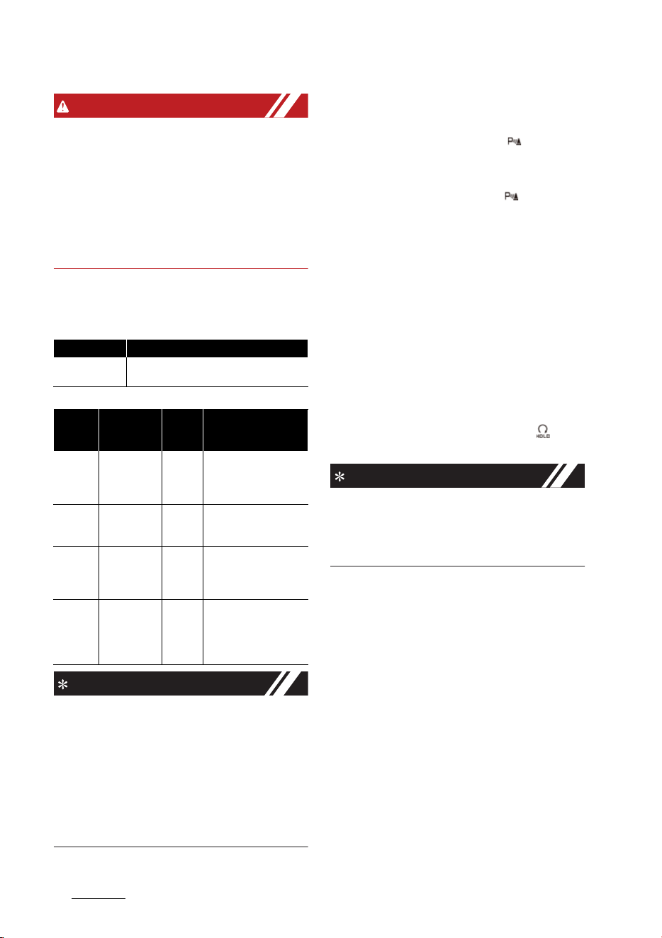
Driving your vehicle
1786
Remote Smart Parking Assist (RSPA)
WARNING
僅 When using Remote Smart Parking
function, make sure that all passen
-
gers have gotten out of the vehicle.
僅 After ending or turning off Remote
Smart Parking function, before leav
-
ing the vehicle, close windows and
sunroofs, and make sure the vehicle is
off before locking the doors.
Smart Parking function
NOTICE
僅 Operation status by the hazard warn
-
ing light may not be applicable based
on the regulation of your country.
僅 If the smart key is not within the oper
-
ating range from the vehicle (approxi
-
mately 4m (13 ft.)), the smart key LED
will not illuminate or blink. Use the
smart key within the operating range.
How to turn off Parking function
while operating
僅 Press the Parking Safety ( ) button
or select
Cancel
on the infotainment
system screen to turn off.
僅 Press the Parking Safety ( ) button in
Searching for parking space and
Select parking type stage.
僅 Shift the gear to R (Reverse) in the in
Searching for parking space, Select
parking type and Select operating
mode stage.
僅 While Smart Parking function is oper
-
ating, depress the brake pedal to stop
the vehicle. At this time, EPB (Elec
-
tronic Parking Brake) will not be
engaged.
僅 While Smart Parking function is oper
-
ating, press the Remote Start ( ) but
-
ton on the smart key.
NOTICE
Get on the vehicle with the smart key.
Remote Smart Parking function will turn
off. At this time, the vehicle will remain
on.
Parking function operation status
The function will pause in the fol
-
lowing conditions when:
When Parking function is paused, the
vehicle will automatically stop. If the con
-
dition that made the function to pause
disappears, the function may operate
again.
僅Smart Parking
- There is a pedestrian, animal or
object in the direction the vehicle is
moving
- The door or tailgate is open
Operation status Turn signal
Under control
The turn signal of the parking direction
blinks until the first reverse is complete.
Opera
-
tion sta
-
tus
Smart key
LED
Hazard
warning
light
Turn signal
Under
control
Green LED
continuously
blinks
-
The turn signal of the
parking direction blinks
until the first reverse is
complete.
Pause
Red LED con
-
tinuously
blinks
Blinks -
Off
Red LED illu
-
minates for 4
seconds and
then turns off
Blinks 3
times
and
turns off
-
Complete
Green LED
illuminates for
4 seconds
and then
turns off
Blinks 1
time and
turns off
-

179
6
6
Driving your vehicle Remote Smart Parking Assist (RSPA)
- The driver's seat belt is not fas
-
tened
- Blind-Spot Collision-Avoidance
Assist or Rear-Cross Traffic Colli
-
sion Assist operates while the vehi
-
cle is being controlled in the reverse
direction
- The Parking/View ( ) button is not
continuously pressed
- The vehicle is stopped by depress
-
ing the brake pedal
僅Remote Smart Parking
- There is a pedestrian, animal or
object in the direction the vehicle is
moving
- The door or tailgate is open
- The Forward ( ) or Backward ( )
button is not continuously pressed
- Simultaneously pressing multiple
buttons on a smart key
- The smart key is not operated
within 4 m (13 ft.) from the vehicle
- Button of another smart key is
pressed in addition to the operating
smart key
- Blind-Spot Collision-Avoidance
Assist or Rear-Cross Traffic Colli
-
sion Assist operates while the vehi
-
cle is being controlled in the reverse
direction
The function will cancel in the fol
-
lowing conditions when:
僅Smart Parking
When Smart Parking function is can
-
celed, the vehicle will automatically
stop, shift the gear to P (Park) and
engage EPB (Electronic Parking
Brake).
- The steering wheel is steered
- The gear is shifted while the vehicle
is moving
- Operating EPB while the vehicle is
moving
- The hood is open
- The driver opens the door with the
seatbelt unfastened
- Rapid acceleration occurs
- Vehicle skid occurs
- The wheel is stuck by an obstacle
and cannot move
- There are pedestrians, animals or
objects at the front and rear of the
vehicle at the same time
- Approximately 3 minutes and 50
seconds have past after Smart
Parking function has started to
operate
- The slope of the road exceeds the
operational range
- The function is paused for more
than 1 minute
- The steering wheel, gearshift, brak
-
ing, and drive controls are not
working normally
- ABS, TCS or ESC system operates
due to slippery road conditions
- The charging door opens
僅 Remote Smart Parking
When Remote Smart Parking function
is canceled, the vehicle will automati
-
cally stop, shift the gear to P (Park)
and engage EPB (Electronic Parking
Brake).
- The steering wheel is steered
- The gear is shifted
- Operating EPB while the vehicle is
moving
- The hood is open
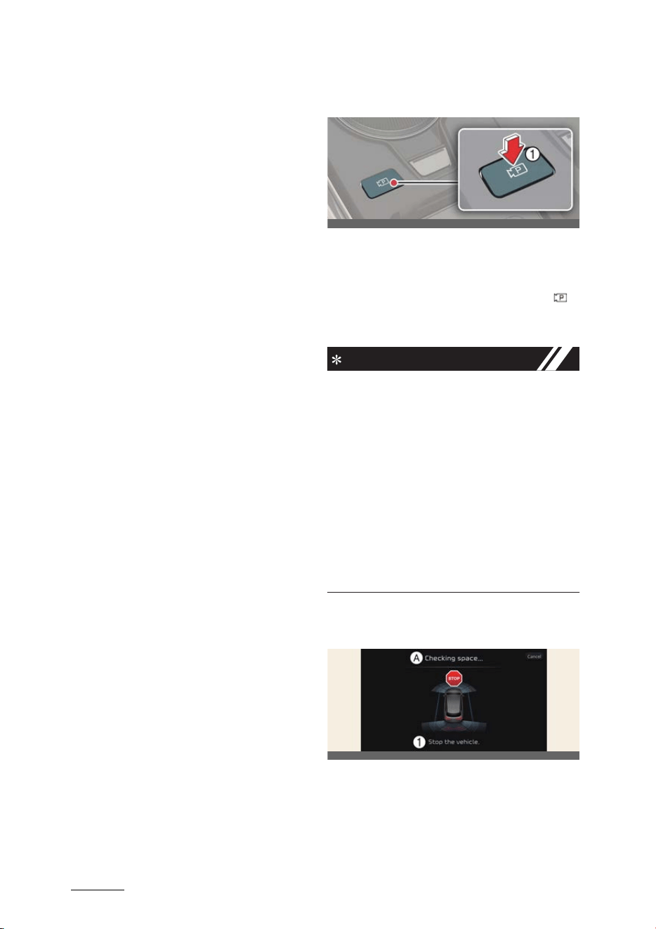
Driving your vehicle
1806
Remote Smart Parking Assist (RSPA)
- The brake pedal or accelerator
pedal is depressed when all the
doors are closed
- The smart key is outside the vehicle
when the brake pedal is depressed
while the driver's door is open.
- Rapid acceleration occurs
-Vehicle skid occurs
- The wheel is stuck by an obstacle
and cannot move
- There are pedestrians, animals or
objects at the front and rear of the
vehicle at the same time
- Approximately 3 minutes and 50
seconds have past after Remote
Smart Parking function has started
to operate
- The slope of the road exceeds the
operational range
- The function is paused for more
than 1 minute
- The steering wheel, gearshift, brak
-
ing, and drive controls are not
working normally
- There is a problem with the smart
key or the smart key battery is low
- ABS, TCS or ESC system operates
due to slippery road conditions
- The alarm of the Theft Alarm Sys
-
tem sounds
- The charging door opens
Smart Exit
Operating order
Smart Exit function operates in the fol
-
lowing order:
1. Getting ready for exit
2. Checking space
3. Select exit direction
4. Smart Exit
1. Getting ready for exit
1. With the vehicle turned on, depress
the brake pedal and shift the gear to P
(Park) or N (Neutral).
2. Press and hold the Parking/View ( )
button to turn on Remote Smart Park
-
ing Assist.
NOTICE
僅
Agree
must be selected on the info
-
tainment system screen and the info
-
tainment system has to operate
properly to use Smart Exit function.
僅 Drive below 5 km/h (3 mph) with the
vehicle on and shift the gear to N
(Neutral), Smart Exit function can be
used.
僅 If the function is turned on again after
parallel parking is completed by
Remote Smart Parking Assist, Smart
Exit function can be used.
2. Checking space
A:
Checking space...
1 Stop the vehicle.
1. When the vehicle is stopped by
depressing the brake pedal, the vehi
-
cle sensors will detect the distance
OCV051092L
OCVGT042205L
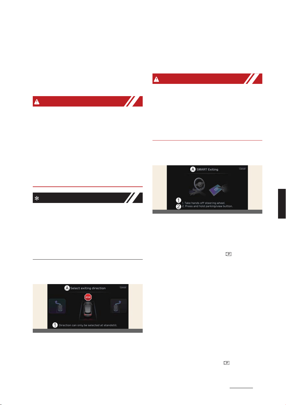
181
6
6
Driving your vehicle Remote Smart Parking Assist (RSPA)
from nearby objects and check for
space to exit.
2. When checking for space is complete,
a message will appear on the infotain
-
ment system screen with an audible
sound to notify the search is com
-
plete.
WARNING
僅 While checking for space, if there is a
risk of collision with pedestrian, ani
-
mal or object in the direction of vehi
-
cle exit, for your safety, Smart Exit
function can be turned off.
僅 Even if check for space is completed,
objects in the blind spot area cannot
be detected by the sensors. The driver
must directly check the blind spot
area and continue using the function.
NOTICE
Due to abnormal performance of the
ultrasonic sensor or the influence of the
surroundings, Parking function may not
be able to search for a parking space
even if there is a parking space, or may
search for a space that is not suitable for
parking.
3. Select exiting direction
A:
Select exiting direction
1 Direction can only be selected at
standstill.
1. With the vehicle stopped by depress
-
ing the brake pedal, the infotainment
system screen displays the possible
directions for parallel exit.
2. Touch the infotainment system screen
to select the desired exit direction.
WARNING
Before selecting the Exit Direction, the
driver should check whether the space
for exit is suitable. If the searched exit
space by Remote Smart Parking Assist is
narrow or unsuitable (surrounding vehi
-
cles are parked vertically, etc.), do not
use the Smart Exit function.
4. Smart Exit
A:
SMART Exiting
1 1. Take hands off steering wheel.
2 2. Press and hold Parking/View but
-
ton.
1. Press the Parking/View ( ) button
when the vehicle is stopped by
depressing the brake pedal.
僅 When the brake pedal is released,
Remote Smart Parking Assist will
automatically control the steering
wheel, vehicle speed and gearshift.
僅 While Smart Exit function is operat
-
ing, if you do not hold down the
Parking/View button, the vehicle
will stop and function control will
pause. The function will start oper
-
ating again when the Parking/View
button is pressed and held again.
2. Hold the Parking/View ( ) button
until the vehicle reaches the target
OCVGT042200L
OCVGT042201L

Driving your vehicle
1826
Remote Smart Parking Assist (RSPA)
exit location. When the vehicle
reaches the target exit location, a
message will appear on the infotain
-
ment system screen to inform you
that exit is complete.
僅 When the vehicle reaches the tar
-
get exit location, a message will
appear on the infotainment system
screen to inform you that exit is
complete.
NOTICE
僅 Smart Exit function will not operate if
the door is open or the seat belt is not
fastened.
僅 Vehicle speed can be adjusted by
depressing the brake pedal while
Smart Exit function is operating. How
-
ever, the vehicle does not accelerate
even when the accelerator pedal is
depressed.
僅 If exit is completed while depressing
the brake pedal, Smart Exit function
will complete with the gear in D
(Drive).
僅 If exit is completed while depressing
the accelerator pedal, you must take
your foot off the accelerator pedal
once for the accelerator pedal to
operate.
僅 If there is no vehicle operation such as
depressing the brake pedal or accel
-
erator pedal within 4 seconds after
exit is complete, the vehicle will auto
-
matically shift to P (Park) and engage
EPB (Electronic Parking Brake).
僅 After Exit function is complete, always
check the surroundings before driv
-
ing.
Smart Exit operation status
How to turn off Smart function
while operating
僅 Press the Parking/View ( ) button in
the following stage:
-Checking space
- Select exit direction
僅 Shift the gear to R (Reverse) in the fol
-
lowing stage:
-Checking space
- Select exit direction
僅 Press the Parking Safety ( ) button
or select
Cancel
on the infotainment
system screen to turn off Exit func
-
tion.
僅 While Smart Exit function is operating,
if the vehicle is stopped by depressing
the brake pedal, and the gear is
shifted, Exiting function will turn off.
At this time, EPB (Electronic Parking
Brake) will not be engaged.
The function will pause in the fol
-
lowing conditions when:
When Exit function is paused, the vehicle
will stop. If the condition that made the
function to pause disappears, the func
-
tion may operate again.
僅 There is a pedestrian, animal or object
in the direction the vehicle is moving
僅 The door or tailgate is open
僅 The driver's seat belt is not fastened
僅 Blind-Spot Collision-Avoidance Assist
or Rear-Cross Traffic Collision Assist
operates while the vehicle is being
controlled in the reverse direction
Operation status Turn signal
Under control
The turn signal of the exit direction blinks
until the exit is complete or Smart Exit is
canceled.
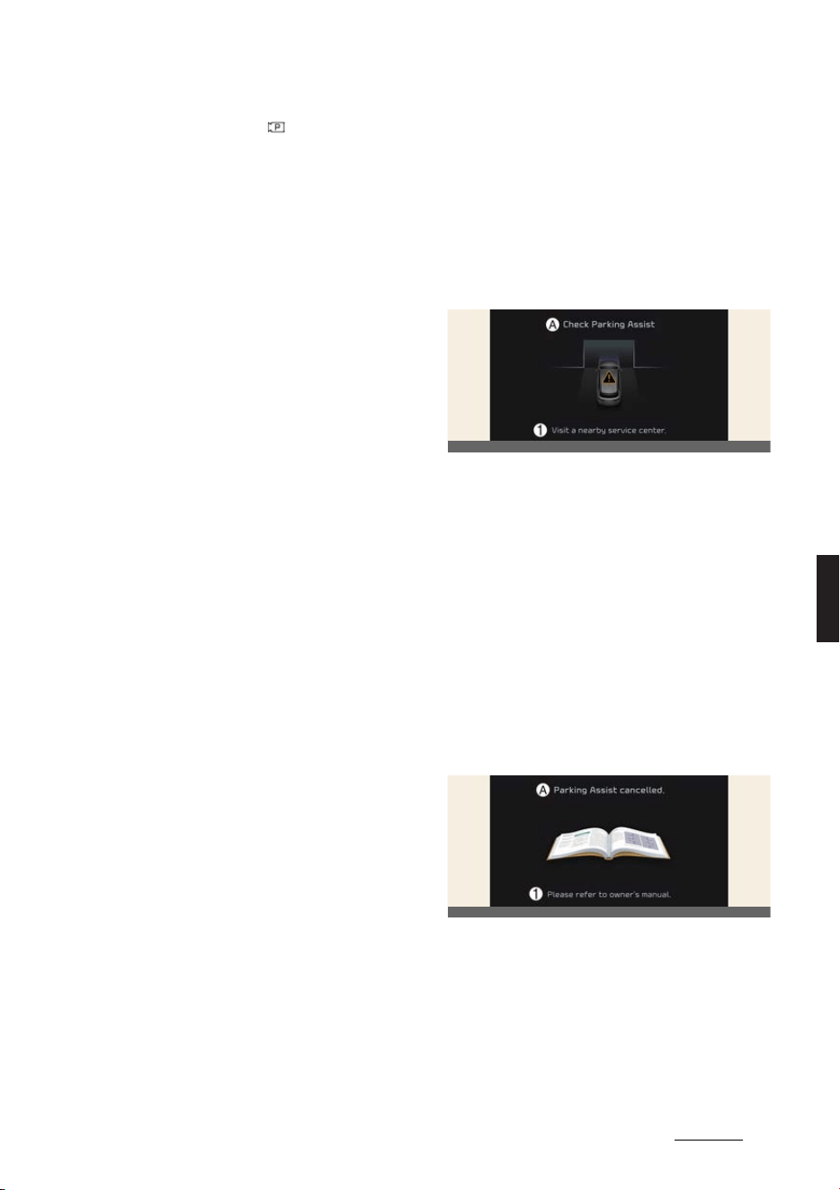
183
6
6
Driving your vehicle Remote Smart Parking Assist (RSPA)
僅 The Parking/View ( ) button is not
continuously pressed
僅 The vehicle is stopped by depressing
the brake pedal
The function will cancel in the fol
-
lowing conditions when:
When Smart Exit function is canceled,
the vehicle will automatically stop, shift
the gear to P (Park) and engage EPB
(Electronic Parking Brake).
僅Smart Exit
- The steering wheel is steered
- The gear is shifted while the vehicle
is moving
- Operating EPB while the vehicle is
moving
- The hood is open
- The driver opens the door with the
seatbelt unfastened
- Rapid acceleration occurs
- Vehicle skid occurs
- The wheel is stuck by an obstacle
and cannot move
- There are pedestrians, animals or
objects at the front and rear of the
vehicle at the same time
- Approximately 3 minutes and 50
seconds have past after Smart Exit
function has started to operate
- The slope of the road exceeds the
operational range
- The function was paused for more
than 1 minute
- The steering wheel, gearshift, brak
-
ing, and drive controls are not
working normally
- ABS, TCS or ESC system operates
due to slippery road conditions
- The charging door opens
Remote Smart Parking Assist
malfunction and limitations
Remote Smart Parking Assist
malfunction
Remote Smart Parking Assist
check
A:
Check Parking Assist
1 Visit a nearby service center.
When Remote Smart Parking Assist is
not working properly, the
Check Park
-
ing Assist
warning message will appear
on the infotainment system screen. If the
message appears, stop using the func
-
tion, and we recommend that the func
-
tion be inspected by an authorized Kia
dealer/service partner.
Remote Smart Parking Assist
canceled
A:
Parking Assist cancelled.
1 Please refer to owner's manual.
When Remote Smart Parking Assist is
operating, the function can be canceled,
and the
Parking Assist Cancelled.
warning message may appear regard
-
less of the parking order. Other mes
-
OCV041207L
OCV041208L
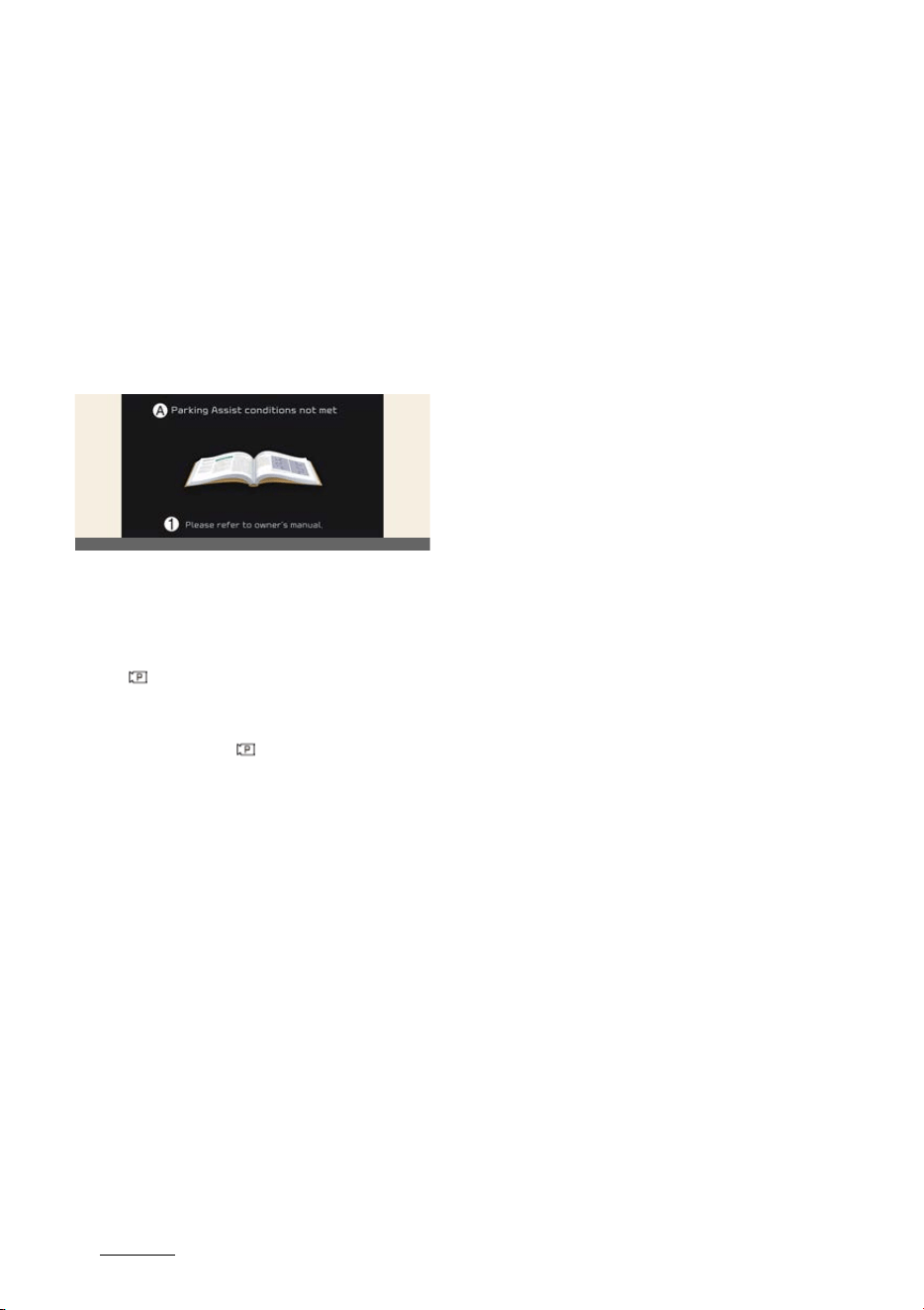
Driving your vehicle
1846
Remote Smart Parking Assist (RSPA)
sages may appear depending on the
situations. Follow the instructions pro
-
vided on the infotainment system screen
while parking your vehicle with Remote
Smart Parking Assist. Always look
around and pay attention when using
the function.
Remote Smart Parking Assist
standby
A:
Parking Assist conditionst met
1 Please refer to owner's manual.
When
Parking Assist conditions not
met
message appears, when Parking/
View ( ) button has been pressed and
held, Remote Smart Parking Assist is in
standby. After a while, press and hold
the Parking/View ( ) button again to
see if the function works.
The message appears even when the
smart key's battery is low. Check the
smart key battery level.
Limitations of Remote Smart
Parking Assist
In the following circumstances, function
performance to park or exit the vehicle
may be limited, there may be a risk of
collision, or Remote Smart Parking Assist
may turn off. Park or exit the vehicle
manually if necessary.
僅 An object is attached to the steering
wheel
僅 The vehicle is installed with a snow
chain, spare tire or different size
wheel
僅 Tire pressure is lower or higher than
the standard tire pressure
僅 Your vehicle is loaded with cargo lon
-
ger or wider than your vehicle or a
trailer is connected to your vehicle
僅 There is a problem with the wheel
alignment
僅 Your vehicle is leaned severely to one
side
僅 Your vehicle is equipped with a trailer
hitch
僅 The license plate is installed differ
-
ently from the original location
僅 There is a person, animal or object
above or below the ultrasonic sensor
when Remote Smart Parking Assist is
activated
僅 The parking space is curved or diago
-
nal
僅 There is an obstacle such as a person,
animal or object (trash can, bicycle,
motorcycle, shopping cart, narrow pil
-
lar etc.) near the parking space
僅 There is a circular pillar or narrow pil
-
lar, or a pillar surrounded by objects
such as fire extinguisher, etc. near the
parking space
僅 The road surface is bumpy (curb
-
stone, speed bump, etc.)
僅 The road is slippery
僅 The parking space is near a vehicle
with higher ground clearance or big,
such as a truck, etc.
僅 The parking space is Inclined
僅 There is heavy wind
僅 Operating Remote Smart Parking
Assist on uneven roads, gravel roads,
bushes, etc.
僅 The performance of the ultrasonic
sensor is affected by extremely hot or
cold weather
OCV041209L
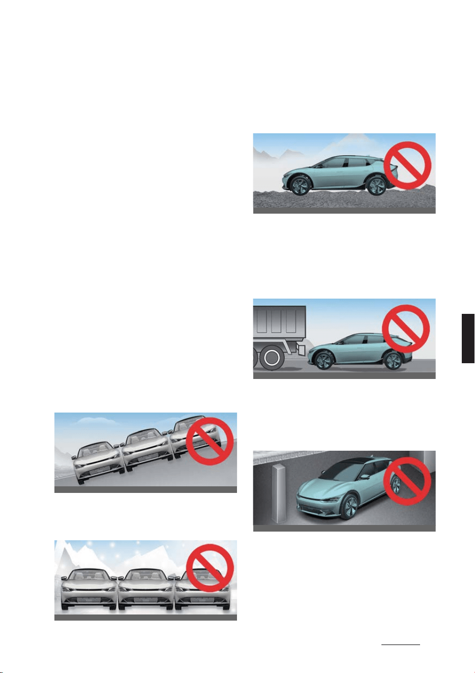
185
6
6
Driving your vehicle Remote Smart Parking Assist (RSPA)
僅 The ultrasonic sensor is covered with
snow or water
僅 An object that generates ultrasonic
waves is nearby
僅 A wireless device with a transmission
function operates near the ultrasonic
sensors
僅Your vehicle is affected by another
vehicle's Parking Distance Warning
僅 The sensor is mounted or positioned
incorrectly by an impact to the
bumper
僅 When the ultrasonic sensor cannot
detect the following objects: Sharp or
slim objects, such as ropes, chains or
small poles
僅 Objects smaller than 100 cm (40
inches) in length and narrower than
14 cm (6 inches) in diameter
僅 Objects which tend to absorb sensor
frequency, such as clothes, spongy
material or snow
Remote Smart Parking Assist may not
operate normally under the following
circumstances:
僅 Parking on inclines
Park manually when parking on
inclines.
僅 Parking in snow
Snow may interfere with sensor oper
-
ation, or Remote Smart Parking Assist
may cancel if the road is slippery
while parking.
僅 Parking on uneven road
Remote Smart Parking Assist may
cancel when the vehicle slips, or the
vehicle cannot move due to road con
-
ditions such as pebbles or fragmented
stones.
僅Parking behind a truck
Do not use Remote Smart Parking
Assist around vehicles with higher
ground clearance, such as a bus,
truck, etc. It may lead to an accident.
僅 Parking near a pillar
Remote Smart Parking Assist perfor
-
mance may reduce or collision with an
obstacle may occur when there is a
narrow object, circular pillar, square
pillar, or a pillar surrounded by objects
such as a fire extinguisher, etc. near
OCV051094L
OCV051095L
OCV051096L
OCV051097L
OCV051098K
Driving your vehicle
1866
Remote Smart Parking Assist (RSPA)
the parking space. The driver should
park the vehicle manually.
僅 Parking in a parking space with a
vehicle on one side only
If Remote Smart Parking Assist is
used, when parking in a parking
space with a vehicle only on one side,
your vehicle may cross the parking
line to avoid the parked vehicle.
僅Parking diagonal
Remote Smart Parking Assist does not
provide diagonal parking. Even if your
vehicle was able to enter the parking
space, do not use the function
because the function cannot operate
normally.
僅 Leaving a parking space near a wall or
parking in a narrow space
- Remote Smart Parking Assist may
not operate properly when leaving
a parking space that is narrow and
near a wall. Always check for
pedestrians, animals, objects while
leaving.
- For your safety, Remote Smart
Parking Assist does not search for
parking spaces at areas with nar
-
row parking spaces that are nar
-
rower than the minimum space
required for parking.
WARNING
僅 The driver is responsible for safe
parking and exit when using Remote
Smart Parking Assist.
僅 When using Remote Smart Parking
Assist, stay out of the way in the direc
-
tion the vehicle moves for your safety.
僅 Always check surroundings when
using Remote Smart Parking Assist.
You may collide with pedestrians, ani
-
mals, or objects if they are near the
sensor or are in the sensor's blind spot
area.
僅 A collision may occur if a pedestrian,
animal, or object suddenly appears
while Remote Smart Parking Assist is
operating.
僅 Do not use Remote Smart Parking
Assist when under the influence of
alcohol.
僅Do not let children or other people to
use the smart key.
僅 If Remote Smart Parking Assist is
used continuously for a long period, it
may adversely affect Remote Smart
Parking Assist performance.
僅 Remote Smart Parking Assist may not
operate normally if the vehicle needs
wheel alignment adjustment such as
when the vehicle tilts to one side. We
recommend that the vehicle be
inspected by an authorized Kia
dealer/service partner.
OCV051099L
OCV051100L
OCV051101L
187
6
6
Driving your vehicle Declaration of conformity
僅 Noise may be heard when braking
occurs by Remote Smart Parking
Assist or when the brake pedal is
depressed by the driver.
僅 Remote Smart Parking Assist may
suddenly apply the brake to avoid col
-
lision.
僅 Use Remote Smart Parking Assist only
in a parking space that is large
enough for the vehicle to move safely.
NOTICE
僅 If the 3rd stage warning (continuous
beep) of the Forward/Reverse Parking
Distance Warning sounds while
Remote Smart Parking Assist is oper
-
ating, it means the obstacle detected
is close to your vehicle. At this time,
Remote Smart Parking Assist will tem
-
porarily stop operating. Make sure
there are no pedestrians, animals, or
objects around your vehicle.
僅 Depending on brake operation, the
stop lights may come on while the
vehicle is moving.
僅 If the vehicle is remotely started that
has been parked in cold weather for a
long time, the operation of Remote
Smart Parking function may be
delayed or canceled depending on
vehicle condition.
Declaration of conformity (if
equipped)
The radio frequency components
(Front Radar) complies:
For Europe and countries subject
to CE certification
For Taiwan
CCAF19LP2840T0
OGL3051237L
OGL3051238L
OGL3051239L
Driving your vehicle
1886
Declaration of conformity
For Australia
For Serbia
For Oman
For Moldova
For Ukraine
OGL3051240L
OGL3051241L
OGL3051242L
OGL3051243L
OGL3051244L
OGL3051245L
OGL3051246L
189
6
6
Driving your vehicle Declaration of conformity
For UAE
For Brazil
For Ghana
For Singapore
For Russia
For Malaysia
For Jordan
For Mexico
For Israel
For Morocco
OGL3051247L
OGL3051248L
OGL3051250L
OGL3051249L
OGL3051251L
OGL3051252L
OGL3051253L
OGL3051254L
OGL3051255L
OGL3051256L
Driving your vehicle
1906
Declaration of conformity
For Argentina
For Philippines
For Paraguay
For Uzbekistan
For Benin
For Thailand
The radio frequency components
(Front Corner Radar/Rear Corner
Radar) complies: (if equipped)
For Mexico
For Ukraine
OGL3051257L
OGL3051258L
OGL3051259L
OGL3051260L
OGL3051261L
OGL3051262L
OGL3051265L
OGL3051266L
191
6
6
Driving your vehicle Declaration of conformity
For Ghana
For Republic of South Africa
For Japan
For Serbia
For Paraguay
For Malaysia
OGL3051267L
OGL3051268L
OGL3051269L
OGL3051270L
OGL3051271L
OGL3051272L
OGL3051273L
Driving your vehicle
1926
Declaration of conformity
For Singapore
For Europe and CE certified coun
-
tries
For Thailand
For Israel
For Brazil
For Taiwan
CCAF20LP2330T5
OSG2PH052093L
OGL3051275L
OGL3051276L
OGL3051277L
OCV051233L
OCV051234L
OGL3051239L
193
6
6
Driving your vehicle Declaration of conformity
For UAE
For Jordan
For Australia
For United Kingdom
For Morocco
For Indonesia
For Pakistan
OCV051235L
OCV051236L
OSG2PH052094L
OGL3051241L
ONQ5EP051154L
OSG2EV052167L
OSG2EV052168L
OSG2EV052169L
Driving your vehicle
1946
Special driving conditions
For Oman
For Nigeria
Special driving conditions
If driving conditions deteriorate due to
poor weather or road conditions, you
should pay even more attention than
usual.
Hazardous driving conditions
When hazardous driving conditions are
encountered, such as water, snow, ice,
mud, sand, or similar hazards, follow
these suggestions:
僅 Drive cautiously and allow extra dis
-
tance for braking.
僅 Avoid sudden braking or steering.
僅 Do not pump the brake pedal on a
vehicle equipped with ABS.
僅 If stalled in snow, mud, or sand, use
second gear. Accelerate slowly to
avoid spinning the drive wheels.
僅 Use sand, rock salt, or other nonslip
material under the drive wheels to
provide traction when the vehicle is
stuck in ice, snow, or mud.
Reducing the risk of a rollover
This multi-purpose passenger vehicle is
defined as a Sports Utility Vehicle (SUV).
Utility vehicles have a significantly
higher rollover rate than other types of
vehicles. SUVs have higher ground
clearance and narrower track to make
them capable of performing in a wide
variety of off-road applications.
Specific design characteristics give them
a higher center of gravity than ordinary
vehicles. An advantage of the higher
ground clearance is a better view of the
road, which allows you to anticipate
problems.
They are not designed for cornering at
the same speeds as conventional pas
-
senger vehicles, any more than low-
OSG2EV052170L
OSG2EV052171L

195
6
6
Driving your vehicle Special driving conditions
slung sports vehicles are designed to
perform satisfactorily in off-road condi
-
tions. Due to this risk, driver and passen
-
gers are strongly recommended to
buckle their seat belts.
In a rollover crash, an unbelted person is
significantly more likely to die than a
person wearing a seat belt. There are
precautionary measures that a driver
can take to reduce the risk of rollover.
If possible, avoid sharp turns and abrupt
maneuvers, do not load your roof rack
with heavy cargo, and never modify
your vehicle in any way.
WARNING
僅 Your vehicle is equipped with tires
designed to provide safe ride and
handling capability. Do not use tires
and wheels that are different in size
and type from the originally installed
ones. It can affect the safety and per
-
formance of your vehicle, which could
lead to steering failure or rollover and
serious injury. When replacing the
tires, be sure to equip all four tires
with the tire and wheel of the same
size, type, tread, brand and load-car
-
rying capacity.
僅 As with other Sports Utility Vehicle
(SUV), failure to operate this vehicle
correctly may result in loss of control,
an accident or vehicle rollover.
- Utility vehicles have a significantly
higher rollover rate than other
types of vehicles.
- Specific design characteristics
(higher ground clearance, narrower
track, etc.) give this vehicle a higher
center of gravity than ordinary
vehicles.
- A SUV is not designed for cornering
at the same speeds as conventional
vehicles.
- Avoid sharp turns and abrupt
maneuvers.
- In a rollover crash, an unbelted per
-
son is significantly more likely to die
than a person wearing a seat belt.
Make sure everyone in the vehicle
is properly buckled up.
Rocking the vehicle
If it is necessary to rock the vehicle to
free it from snow, sand, or mud, first
turn the steering wheel right and left to
clear the area around your front wheels.
Then, shift back and forth between R
(Reverse) and any forward gear position.
Do not race the vehicle, and spin the
wheels as little as possible. If you are still
stuck after a few tries, have the vehicle
pulled out by a tow vehicle to avoid vehi
-
cle overheating and possible damage to
the reduction gear.
WARNING
Do not attempt to rock the vehicle if
people or objects are nearby. The vehi
-
cle may suddenly move forward or
backwards as it becomes unstuck.
CAUTION
僅 Prolonged rocking may cause vehicle
overheating, reduction gear damage
or failure, and tire damage.
僅 Do not spin the wheels, especially at
speeds more than 56 km/h (35 mph).
Spinning the wheels at high speeds
when the vehicle is stationary could
overheat and damage tires, and the
rotating wheels may fly away and
injure bystanders.

Driving your vehicle
1966
Special driving conditions
NOTICE
The Electronic Stability Control (ESC)
should be turned OFF prior to rocking
the vehicle.
Smooth cornering
Avoid braking or gear changing while
cornering, especially when the road is
wet. Ideally, corners should always be
negotiated with gentle acceleration. If
you follow these suggestions, tire wear
will be kept to a minimum.
Driving at night
Because night driving presents more
hazards than driving in the daylight,
here are some important tips to remem
-
ber:
僅 Slow down and keep more distance
between you and other vehicles as it
may be more difficult to see at night,
especially in areas where there are no
street lights.
僅 Adjust your mirrors to reduce the
glare from other driver's headlamps.
僅 Keep your headlamps clean and prop
-
erly aimed. (On vehicles not equipped
with the automatic headlamp aiming
feature.) Dirty or improperly aimed
headlamps will make it much more
difficult to see at night.
僅 Avoid staring directly at the head
-
lamps of oncoming vehicles. You
could be temporarily blinded, and it
will take several seconds for your eyes
to readjust to the darkness.
Driving in the rain
Rain and wet roads can make driving
dangerous, especially if you are not pre
-
pared for the slick surface.
Here are a few things to consider when
driving in the rain:
僅 A heavy rainfall will make it harder to
see and will increase the distance
needed to stop your vehicle, so slow
down.
僅 Keep your windshield-wiping equip
-
ment in good shape. Replace your
windshield wiper blades when they
show signs of streaking or missing
areas on the windshield.
僅 If your tires are not in good condition,
having to stop quickly on a wet sur
-
face can cause a skid and possibly
lead to an accident. Be sure your tires
are in good shape.
僅 Turn on your headlamps to make it
easier for others to see you.
僅 Driving too fast through large puddles
can affect your brakes. If you must
drive through puddles, try to go
through them slowly.
僅 If you believe you got your brakes
wet, apply them lightly while driving
until normal brake operation returns.
Hydroplaning
If the road is wet enough and you are
going fast enough, your vehicle may
have little or no contact with the road
surface and actually ride on the water.
The best advice is to SLOW DOWN when
the road is wet.
The risk of hydroplaning increases as
the depth of tire tread decreases, refer
to"Tire replacement" on page 8-17.

197
6
6
Driving your vehicle Special driving conditions
Driving in flooded areas
Avoid driving through flooded areas
unless you are sure the water is no
higher than the bottom of the wheel
hub. Drive through any water slowly.
Allow adequate stopping distance as
brake performance may be affected.
After driving through water, dry the
brakes by gently applying them several
times while the vehicle is moving slowly.
If the brake system is wet and has
reduced braking effect or frequent
sounds when braking, adjust the setting
for the regenerative braking to '0' speed
with paddle shifter and apply the brake
pedal lightly several times. Maintain a
safe distance to dry the brake system.
Setting the regenerative braking to '0'
may reduce efficiency while braking sev
-
eral times for brake performance, but
this is normal. The regenerative braking
system will be normally operated after
-
wards.
Highway driving
Tires
Adjust the inflation pressures of the tires
in accordance with their specifications.
Low tire inflation pressures will result in
overheating and possible failure of the
tires.
Avoid using worn or damaged tires since
they may provide reduced traction or fail
completely.
Never exceed the maximum tire inflation
pressure shown on the tires.
WARNING
僅 Always check the tires for proper
inflation before driving. Underinflated
or overinflated tires can cause poor
handling, loss of vehicle control, and
sudden tire failure, leading to acci
-
dents, injuries, and even death. For
proper tire pressures, refer to "Tires
and wheels" on page 9-6.
僅 Always check the tire tread before
driving your vehicle. Worn-out tires
can result in loss of vehicle control.
Worn-out tires should be replaced as
soon as possible. For further informa
-
tion and tread limits, refer to "Tires
and wheels" on page 8-15.
Coolant and high voltage battery
Driving at higher speeds on the highway
consumes more electric energy and is
less efficient than driving at a slower,
more moderate speed. Maintain a mod
-
erate speed in order to conserve electric
energy when driving on the highway.
Be sure to check both the coolant level
and the electric energy level before driv
-
ing.

Driving your vehicle
1986
Winter driving
Winter driving
Severe weather conditions in the winter
result in greater wear and other prob
-
lems.
To minimize the problems of winter driv
-
ing, you should follow these sugges
-
tions:
* Snow tires and tire chains for the
national language (Icelandic), see the
Appendix.
Snowy or icy conditions
To drive your vehicle in deep snow, it
may be necessary to use snow tires or to
install tire chains on your tires.
If snow tires are needed, it is necessary
to select tires of the size and type equiv
-
alent to the tires originally installed. Fail
-
ure to do so may adversely affect the
safety and handling of your vehicle. Fur
-
thermore, speeding, rapid acceleration,
sudden brake applications, and sharp
turns are potentially very hazardous
practices.
During deceleration, use vehicle braking
to the fullest extent. Sudden brake appli
-
cations on snowy or icy roads may cause
skids to occur. You need to keep suffi
-
cient distance between your vehicle and
the one in front. Also, apply the brake
gently. Note that installing tire chains on
the tires will provide greater driving
force, but will not prevent side skids.
Summer tires (if equipped)
僅 Summer tires are used to maximize
the driving performance on dry roads.
僅 If the temperature is below 7°C or you
are driving on snowy or icy roads, the
summer tires lose their brake perfor
-
mance and traction as the tire grip
weakens significantly.
僅 If the temperature is below 7°C or you
are driving on snowy or icy roads,
mount snow tires or all-season tires of
the same size with your vehicle's stan
-
dard tire for safe driving. Both snow
and all-season tires have M+S mark
-
ings.
僅When using the M+S tires, use tires
with the same tread produced by the
same manufacturer for safe driving.
僅 When driving with the M+S tires with
the lower maximum allowable speed
than that of the vehicle's standard
summer tire, be careful not to exceed
the speed allowed for the M+S tires.
Snow tires
If you mount snow tires on your vehicle,
make sure they are radial tires of the
same size and load range as the original
tires. Mount snow tires on all four wheels
to balance your vehicle's handling in all
weather conditions. Keep in mind that
the traction provided by snow tires on
dry roads may not be as high as the
traction provided by the tires originally
installed on your vehicle. You should
drive cautiously even when the roads
are clear. Check with the tire dealer for
maximum speed recommendations.
Do not install studded tires without first
checking all applicable regulations for
possible restrictions on their use.
WARNING
Snow tires should be equivalent in size
and type to the vehicle's standard tires.
Otherwise, the safety and handling of
your vehicle may be adversely affected.

199
6
6
Driving your vehicle Winter driving
Tire chains
Fabric type
Because the sidewalls of radial tires are
thinner, they can be damaged by
mounting some types of snow chains on
them. Therefore, the use of snow tires is
recommended instead of snow chains.
Do not mount tire chains on vehicles
equipped with aluminum wheels; snow
chains may cause damage to the
wheels.
Damage to your vehicle caused by
improper snow chain use is not covered
by your vehicle manufacturer's war
-
ranty.
When using tire chains, attach them to
the drive wheels as follows.
僅 Rear wheel drive vehicle moves the
rear wheel as a power source. Thus,
snow chains must be mounted to rear
tires.
僅 All wheel drive vehicle must mount
snow chains to rear tires only. In this
situation, minimize the driving dis
-
tance in order to prevent damage to
the all-wheel drive system.
僅 After mounting snow chains, drive
slowly. If you hear noise caused by
chains contacting the body, slow
down until the noise stops and
remove the chain as soon as you
begin driving on cleared roads to pre
-
vent damage.
僅 Chains of the wrong size or which are
improperly installed can damage your
vehicle's brake lines, suspension,
body, and wheels. Therefore, when
installing snow chains, follow the
manufacturer's instructions and
mount them as tightly possible. Drive
slowly with chains installed, staying
under 30 km/h (20 mph).
僅 Install tire chains that meet the speci
-
fications of each tire size to prevent
damage your vehicle.
- All of tires use fabric snow chain.
CAUTION
僅 Make sure the snow chains are the
correct size and type for your tires.
Incorrect snow chains can cause dam
-
age to the vehicle body and suspen
-
sion and may not be covered by your
vehicle manufacturer warranty. Also,
the snow chain connecting hooks may
be damaged from contacting vehicle
components causing the snow chains
to come loose from the tire.
僅 Always check chain installation for
proper mounting after driving approx
-
imately 0.5 to 1 km (0.3 to 0.6 miles)
to ensure safe mounting. Retighten or
remount the chains if they are loose.
Check the battery and cables
Winter places additional burden the bat
-
tery system. Visually inspect the battery
and cables as described in section 8.
Have the level of charge in your battery
checked by a professional workshop. Kia
recommends visiting an authorized Kia
dealer/service partner.
To keep the locks from freezing
To keep the vehicle's locks from freez
-
ing, squirt an approved de-icer fluid or
glycerine into the key openings. If a lock
is covered with ice, squirt it with an
OCV051103L

Driving your vehicle
2006
Winter driving
approved de-icing fluid to remove the
ice. If the lock is frozen internally, you
may be able to thaw it out by using a
heated key. Handle the heated key with
care to avoid injury.
Use an approved window washer
anti-freeze for the window
washer system
To keep the water in the window washer
system from freezing, add an approved
window washer anti-freeze solution in
accordance with instructions on the con
-
tainer. Window washer anti-freeze is
available from an authorized Kia dealer/
service partner and most auto parts out
-
lets. Do not use coolant or other types of
anti-freeze as these may damage the
paint finish.
Do not let your parking brake
freeze
Under some conditions, your parking
brake can freeze in the applied position.
This is most likely to happen when there
is an accumulation of snow or ice
around or near the rear brakes or if the
brakes are wet. If there is risk of the
parking brake freezing, temporarily
apply it with the P (Park) gear position
selected. Block the rear wheels in
advance as well so that the vehicle can
-
not roll. Then, release the parking brake.
Do not let ice or snow accumulate
underneath
Under some conditions, snow and ice
can build up under the fenders and
interfere with the steering. When driving
in severe winter conditions where this
may happen, you should periodically
check underneath the vehicle to make
sure the movements of the front wheels
and the steering components are not
obstructed.
Carry emergency equipment
Depending on the severity of the
weather, you should carry appropriate
emergency equipment. Some of the
items you may want to carry include tire
chains, tow straps or chains, flashlight,
emergency flares, sand, shovel, jumper
cables, window scraper, gloves, ground
cloth, coveralls, blanket, etc.
Do not place objects or materials
in the motor compartment
Putting objects or materials in the motor
compartment may cause an motor fail
-
ure. Such damage will not be covered by
the manufacturer's warranty.

201
6
6
Driving your vehicle Trailer towing
Trailer towing (if equipped)
If you are considering towing with your
vehicle, you should first check with the
country's department of motor vehicles
to determine their legal requirements.
Since laws vary, the requirements for
towing trailers, other vehicles, and appa
-
ratus may differ. Kia recommends to ask
an authorized Kia dealer/service partner.
Your vehicle can tow a trailer. To identify
what the vehicle trailering capacity is for
your vehicle, refer to "Weight of the
trailer" on page 6-206 that appears later
in this section.
Remember that trailer towing is different
from simply driving your vehicle by
itself. Trailering means changes in han
-
dling, durability, and electric energy
economy. Successful, safe trailer towing
requires correct equipment, which has
to be used properly.
This section contains many time-tested
and important trailer-towing tips and
safety rules. Many of these are import
-
ant for your safety and that of your pas
-
sengers. Please read this section
carefully before towing a trailer.
WARNING
僅 If you don't use the correct equipment
and drive improperly, you can lose
control when you pull a trailer. For
example, if the trailer is too heavy, the
brakes may not work well - or even at
all. You and your passengers could be
seriously or fatally injured. Pull a
trailer only if you have followed all the
steps in this section.
僅 Before towing, make sure the total
trailer weight, gross combination
weight, gross vehicle weight, gross
axle weight and trailer tongue load
are all within the limits.
CAUTION
Pulling a trailer improperly can damage
your vehicle and result in costly repairs
not covered by your warranty. To pull a
trailer correctly, follow the advice in this
section.
NOTICE
僅 The mounting hole for hitches are
located on both sides of the under
-
body behind the rear tires.
僅 For Europe
- The technically permissible maxi
-
mum load on the rear axle(s) may
be exceeded by not more than 15%
and the technically permissible
maximum laden mass of the vehi
-
cle may be exceeded by not more
than 10% or 100 kg (220.4 lbs),
whichever value is lower. In this
case, do not exceed 100 km/h (62.1
mph) for vehicle of category M1 or
80 km/h (49.7 mph) for vehicle of
category N1.
- When towing a trailer, the addi
-
tional load imposed at the trailer
coupling device may cause the rear
tire maximum load ratings to be
exceeded, but not by more than
15%. In such a case, do not exceed
100km/h, and the rear tire pressure
should be at least 20 kPa(0.2 bar)
above the tire pressure(s) as rec
-
ommended for normal use (i.e.
without a trailer attached).
* M1: passenger vehicle (9-seater or
under)
* N1: commercial vehicle (3.5 ton or
under)

Driving your vehicle
2026
Trailer towing
Hitches
It is important to have the correct hitch
equipment. Crosswinds, large trucks
going by, and rough roads are just a few
reasons why you will need the right
hitch. Here are some rules to follow:
僅 Do you have to make any holes in the
body of your vehicle when you install
a trailer hitch? If you do, be sure to
seal the holes when removing the
hitch later.
If you don't seal them, dirt and water
can get into your vehicle.
僅 The bumpers on your vehicle are not
intended for hitches. Do not attach
rental hitches or other bumper-type
hitches. Use only a frame-mounted
hitch that does not attach to the
bumper.
僅 Any part of the rear number plate or
lighting devices of the vehicle must
not be obscured by the mechanical
coupling device. If the rear number
plate and/or lighting devices can be
obscured partially by any part of the
mechanical coupling device, mechani
-
cal coupling devices that can not be
easily removed or repositioned with
-
out use of any tool, except an easily
operated (i.e. an effort not exceeding
20 N·m) release key which is supplied
by the manufacturer of the coupling
device, are not permitted for
use. Please note that the mechanical
coupling device that is fitted and not
in use must always be removed or
repositioned if the rear number plate
and/or rear lighting devices are
obscured by any part of the mechani
-
cal coupling device.
僅 Kia trailer hitch accessory is available
at an authorized Kia dealer/service
partner.
Safety chains
You should always attach chains
between your vehicle and your trailer.
Cross the safety chains under the
tongue of the trailer so that the tongue
will not drop to the road if it becomes
separated from the hitch.
Instructions about safety chains may be
provided by the hitch manufacturer or
by the trailer manufacturer. Follow the
manufacturer's recommendation for
attaching safety chains. Always leave
just enough slack so you can turn with
your trailer. Never allow safety chains to
drag on the ground.
Trailer brakes
If your trailer is equipped with a braking
system, make sure it conforms to the
country's regulations, and that it is prop
-
erly installed and it is operating cor
-
rectly.
If your trailer weighs more than the max
-
imum trailer weight without trailer
brakes loaded, then it needs its own
brakes, and those trailer brakes must be
adequate. Be sure to read and follow the
instructions for the trailer brakes so that
you will be able to install, adjust, and
maintain them properly.
僅 Do not tap into your vehicle's brake
system.
WARNING
Do not use a trailer with its own brakes
unless you are absolutely certain that
you have properly set up the brake sys
-
tem. This is not a task for amateurs. Use
an experienced, competent trailer shop
for this work.
Driving with a trailer
Towing a trailer requires a certain
amount of experience. Before setting

203
6
6
Driving your vehicle Trailer towing
out for the open road, you must get to
know your trailer. Acquaint yourself with
the feel of handling and braking with the
added weight of the trailer. Always keep
in mind that the vehicle you are driving
is now a lot longer and not nearly as
responsive as your vehicle is by itself.
Before you start, check the trailer hitch
and platform, safety chains, electrical
connector(s), lights, tires, and mirror
adjustment. If the trailer has electric
brakes, start your vehicle and trailer
moving, and then apply the trailer brake
controller by hand to make sure the
brakes are working. This lets you check
your electrical connection at the same
time.
During your trip, check occasionally to
make sure that the load is secure and
that the lights and trailer brakes are still
working.
NOTICE
When the ambient temperature is lower
than 0°C (32°F) and the remaining high
voltage battery is low, the power of the
vehicle with a trailer can be dropped,
causing a trouble in acceleration or drop
of the speed when driving hills.
When driving with a trailer, be sure to
charge the high voltage battery more
than 50% if the ambient temperature is
lower than 0°C (32°F).
Following distance
Stay at least twice as far behind the
vehicle ahead as you would when driv
-
ing your vehicle without a trailer. This
can help you avoid situations that
require heavy braking and sudden turns.
Passing
You will need more passing distance
ahead when towing a trailer. Likewise,
due to the increased vehicle length, you
will need to go much farther beyond the
passed vehicle before you can return to
your lane.
Reversing
Hold the bottom of the steering wheel
with one hand. Then, to move the trailer
to the left, just move your hand to the
left. To move the trailer to the right,
move your hand to the right. Always
reverse slowly and have someone guide
you, if possible.
Making turns
When turning with a trailer, make wider
turns than normal. This is to make sure
that your trailer does not hit soft shoul
-
ders, curbs, road signs, trees, or other
objects. Avoid jerky or sudden maneu
-
vers. Signal well in advance.
Turn signals when towing a
trailer
When you tow a trailer, your vehicle has
to have a different turn signal flasher
and extra wiring. The green arrows on
your instrument cluster will flash when
-
ever you signal a turn or lane change. If
properly connected, the trailer lights will
also flash to alert other drivers to the
fact that you are about to turn, change
lanes, or stop.
When towing a trailer, the green arrows
on your instrument cluster will flash for
turns even if the bulbs on the trailer are
burned out. Thus, you may think drivers
behind you are seeing your signals
when, in fact, they are not. It is important

Driving your vehicle
2046
Trailer towing
to check occasionally to make sure the
trailer bulbs are still working. You must
also check the lights every time you dis
-
connect, and then reconnect the wires.
Do not connect a trailer lighting system
directly to your vehicle's lighting system.
Use only an approved trailer wiring har
-
ness.
Seek assistance from a professional
workshop for the installation of the wir
-
ing harness.
Kia recommends visiting an authorized
Kia dealer/service partner.
WARNING
Failure to use an approved trailer wiring
harness could result in damage to the
vehicle electrical system and/or personal
injury.
Driving on grades
Reduce speed before you start down a
long or steep downgrade.
On a long uphill grade, shift down and
reduce your speed to around 70 km/h
(45 mph) to reduce the possibility of
motor overheating.
CAUTION
僅 To prevent motor overheating:
If you tow a trailer with the maximum
gross vehicle weight and maximum
trailer weight, it can cause the motor
to overheat. When driving in such
conditions, stop the vehicle until it
cools down. You may proceed once
the motor has cooled sufficiently.
When towing a trailer, your vehicle
speed may be much slower than the
general flow of traffic, especially when
climbing an uphill grade. Use the
outer lane when towing a trailer on an
uphill grade. Choose your vehicle
speed according to the maximum
posted speed limit for vehicles with
trailers, the steepness of the grade,
and your trailer weight.
僅 You must decide the driving speed
depending on trailer weight and uphill
grade to reduce the possibility of
motor overheating.
Parking on hills
Generally, if you have a trailer attached
to your vehicle, you should not park your
vehicle on a hill. Both your vehicle and
the trailer can be damaged if they unex
-
pectedly roll down the hill, and people
can be seriously or fatally injured.
If you ever need to park your trailer on a
hill, however, here is how to do it:
1. Pull the vehicle into the parking space.
Turn the steering wheel in the direc
-
tion of the curb (right if headed down
-
hill, left if headed up hill. For right-
hand drive, left if headed down hill,
right if headed up hill).
2. Engage the parking brake and shut
off the vehicle.
3. Place chocks under the trailer wheels
on the downhill side of the wheels.
4. Start the vehicle, hold the brakes, shift
to neutral, release the parking brake,
and slowly release the brakes until the
trailer chocks absorb the load.
5. Reapply the brakes, reapply the park
-
ing brake.
6. Shut off the vehicle and release the
vehicle brakes but leave the parking
brake applied.
WARNING
僅Parking your vehicle on a hill with a
trailer attached could cause serious

205
6
6
Driving your vehicle Trailer towing
injury or death, should the trailer
break loose.
僅 It can be dangerous to get out of your
vehicle if the parking brake is not
firmly set. If you have left the vehicle
running, the vehicle can move sud
-
denly. You or others could be seri
-
ously or fatally injured.
When you are ready to leave
after parking on a hill
1. Apply your brakes and hold the brake
pedal down while:
僅 Start your vehicle;
僅 Shift into gear; and
僅 Release the parking brake.
2. Slowly remove your foot from the
brake pedal.
3. Drive slowly until the trailer is clear of
the chocks.
4. Stop and have someone pick up and
store the chocks.
Maintenance when towing a
trailer
Your vehicle will need to be serviced
more often if you regularly pull a trailer.
Important items to pay particular atten
-
tion to include reduction gear fluid, axle
lubricant and cooling system fluid. Brake
condition is another important item to
check frequently. Each item is covered in
this manual, and the Index will help you
find them quickly. If you are towing a
trailer, it is a good idea to review these
sections before starting your trip.
Do not forget to maintain your trailer
and hitch as well. Make sure you are
aware of the maintenance schedule
specified for your trailer, and that you
carry out its periodic checks. Preferably,
conduct your checks at the start of each
day's driving. Most importantly, all hitch
nuts and bolts should be tight.
CAUTION
僅 Due to higher load during trailer
usage, overheating might occur in hot
days or during uphill driving.
僅 When towing, check the reduction
gear fluid more frequently.
If you do decide to tow a trailer
Here are some important points if you
decide to tow a trailer:
僅 Consider using a sway control. You
can ask a hitch dealer about sway
control.
僅 Do not do any towing with your vehi
-
cle during its first 2,000 km (1,200
miles) in order to allow the motor to
properly break in. Failure to heed this
caution may result in serious motor
damage.
僅 When towing a trailer, Kia recom
-
mends that you consult an authorized
Kia dealer/service partner on addi
-
tional requirements such as a towing
kit, etc.
僅 Always drive your vehicle at moderate
speed of less than 100 km/h (60
mph).
僅 The driving range of Electric Vehicle
could be affected by the shape and
weight of the trailer. Depending on
the trailer, the driving range could
decrease by 50%.
僅 On a long uphill grade, do not exceed
70 km/h (45 mph) or the posted tow
-
ing speed limit, whichever is lower.
僅 The chart contains important consid
-
erations that have to do with weight:

Driving your vehicle
2066
Trailer towing
Weight of the trailer
What is the maximum safe weight of a
trailer? It should never weigh more than
the maximum trailer weight with trailer
brakes. But even that can be too heavy.
It depends on how you plan to use your
trailer. For example, speed, altitude, road
grades, and outside temperature as well
as how often your vehicle is used to tow
a trailer are all important. The ideal
trailer weight can also depend on any
special equipment that you have on your
vehicle.
Weight of the trailer tongue
The tongue load of any trailer is an
important weight to measure because it
affects the total gross vehicle weight
(GVW) of your vehicle. This weight
includes the curb weight of the vehicle,
any cargo you may carry in it, and the
people who will be riding in the vehicle.
And if you tow a trailer, you must add
the tongue load to the GVW because
your vehicle will also be carrying that
weight.
The trailer tongue should weigh a maxi
-
mum of 10% of the total loaded trailer
weight, within the limits of the maximum
trailer tongue load permissible.
After you have loaded your trailer, weigh
the trailer and then the tongue sepa
-
rately to see if the weights are accept
-
able. If they are not, you may be able to
correct them simply by moving some
items around in the trailer.
WARNING
僅 Never load a trailer with more weight
in the rear than in the front. The front
should be loaded with approximately
60% of the total trailer load; the rear
should be loaded with approximately
40% of the total trailer load.
僅 Never exceed the maximum weight
limits of the trailer or trailer towing
equipment. Improper loading can
result in damage to your vehicle and/
or personal injury. Check weights and
loading at a commercial scale or high
-
way patrol office equipped with
scales.
僅 An improperly loaded trailer can
cause loss of vehicle control.
Item
Weight
(Stan
-
dard
type)
Weight
(Extende
d type -
GT Line)
Weight
(Extende
d type -
GT)
Maxi
-
mum
trailer
weight
With brake system
750 kg
(1,653
lbs.)
1,600 kg
(3,527
lbs.)
1,800 kg
(3,968
lbs.)
Without brake sys
-
tem
750 kg
(1,653 lbs.)
Maximum permissible static
vertical load on the coupling
device
100 kg
(220 lbs.)
Recommended distance from
rear wheel center to coupling
point
1,025 mm (40.4 inches)

207
6
6
Driving your vehicle Vehicle weight
Vehicle weight
This section will give you guidance on
the proper loading of your vehicle to
keep your loaded vehicle weight within
its design rating capability. Properly
loading your vehicle will help you use
the vehicle's design performance to
maximum advantage. Before loading
your vehicle, familiarize yourself with the
following terms for determining your
vehicle's weight ratings, which are used
in the vehicle's specifications and on the
certification label (if equipped):
Base curb weight
This is the weight of the vehicle includ
-
ing all standard equipment. It does not
include passengers, cargo, or optional
equipment.
Vehicle curb weight
This is the weight of the vehicle includ
-
ing high voltage battery and all standard
equipment. It does not include passen
-
gers, cargo, or optional equipment.
Cargo weight
This figure includes all weight added to
the Base Curb Weight, including cargo
and optional equipment.
GAW (Gross axle weight)
This is the total weight placed on each
axle (front and rear) - including vehicle
curb weight and all payload.
GAWR (Gross axle weight rating)
This is the maximum allowable weight
that can be carried by a single axle (front
or rear). These numbers are shown on
the certification label (if equipped).
The total load on each axle must never
exceed its GAWR.
GVW (Gross vehicle weight)
This is the base curb weight plus the
actual cargo weight plus passengers.
GVWR (Gross vehicle weight rat
-
ing)
This is the maximum allowable weight of
the fully loaded vehicle (including all
options, equipment, passengers, and
cargo). The GVWR is shown on the certi
-
fication label (if equipped) located on
the driver's (or front passenger's) door
sill.
Overloading
WARNING
Vehicle weight
The gross axle weight rating (GAWR)
and the gross vehicle weight rating
(GVWR) for your vehicle are on the Cer
-
tification Label attached to the driver's
(or front passenger's) door. Exceeding
these ratings can cause an accident or
vehicle damage. You can calculate the
weight of your load by weighing the
items (and people) before putting them
in the vehicle. Be careful not to overload
your vehicle.
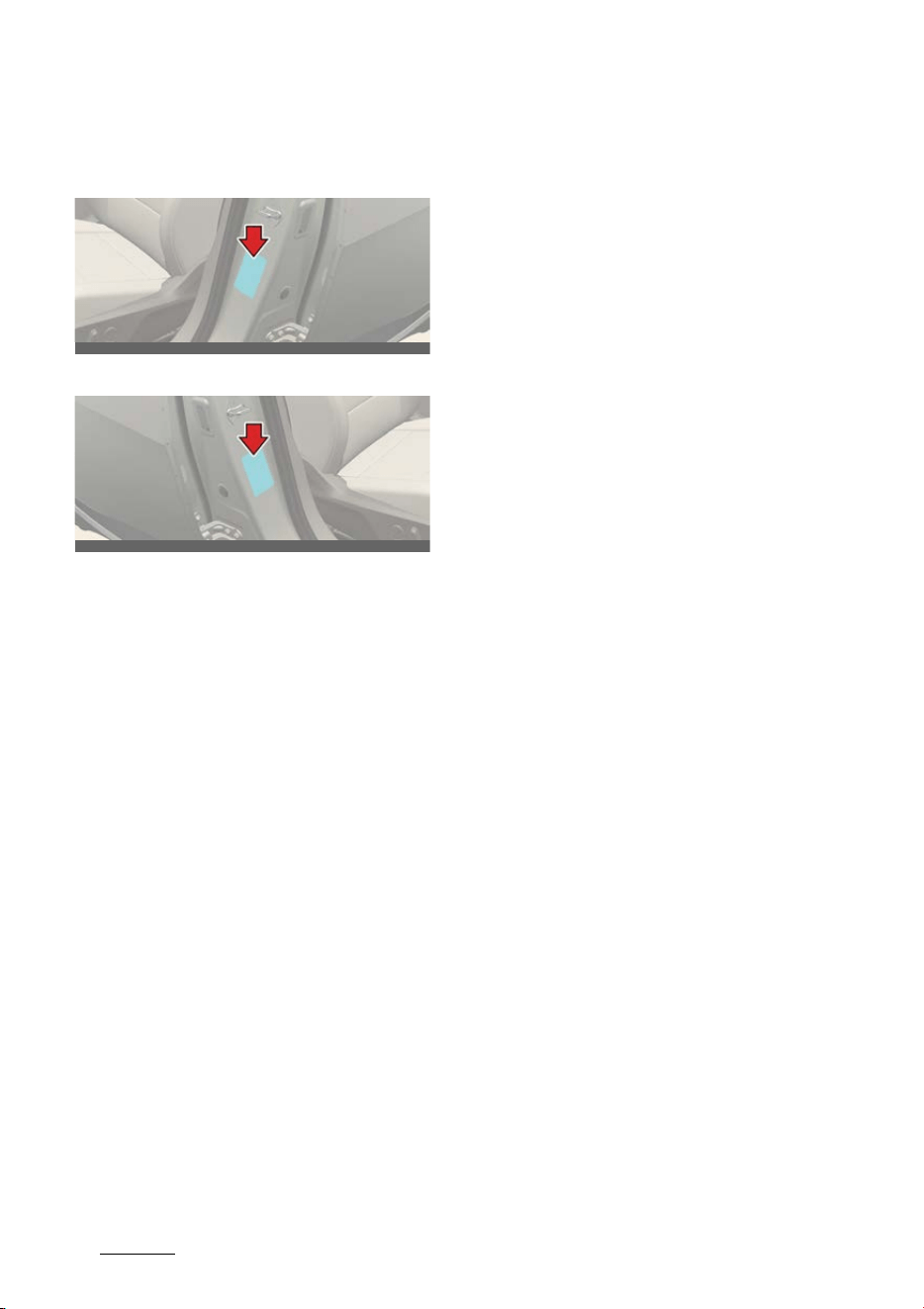
Driving your vehicle
2086
Vehicle weight
Loading Your Vehicle
Certification Label (if equipped)
Tire Label
The Certification/Tire label is found on
the front edge of the RH (or LH) "B" pil
-
lar. The label shows the size of your orig
-
inal tires and inflation pressures needed
to obtain the gross weight capacity of
your vehicle.
This is called the GVWR (Gross Vehicle
Weight Rating). The GVWR includes the
weight of the vehicle, all occupants and
cargo. The Certification/Tire label also
tells you the maximum weights for the
front and rear axles, called Gross Axle
Weight Rating (GAWR).
Never exceed the GVWR for your vehi
-
cle, or the Gross Axle Weight Rating
(GAWR) for either the front or rear axle.
And, if you do have a heavy load, you
should spread it out.
Your warranty does not cover parts or
components that fail because of over
-
loading.
Do not load your vehicle any heavier
than the GVWR or the maximum front
and rear GAWRs. If you do, change to
the vehicle may occur, or it can change
the way your vehicle handles. These
could cause you to lose control. Also,
overloading can shorten the life of your
vehicle.
OCV081003L
OCV081003R

7What to do in an emergency
What to do in an emergency
Road warning................................................................................. 7-3
僅 Hazard warning flasher................................................................................. 7-3
In the event of an emergency while driving .............................. 7-3
僅 If the vehicle stalls while driving................................................................ 7-3
僅 If the vehicle stalls at a crossroad or crossing .................................... 7-3
僅 If you have a flat tire while driving........................................................... 7-3
If the vehicle will not start............................................................7-4
Emergency starting ....................................................................... 7-4
僅 Jump-starting (12V battery)......................................................................... 7-4
僅 Push-starting...................................................................................................... 7-5
Tire Pressure Monitoring System (TPMS) ..................................7-6
僅 Checking the tire pressure........................................................................... 7-6
僅 When the telltale lights up ............................................................................7-7
僅 Tire Pressure Monitoring System (TPMS) malfunction
indicator ............................................................................................................... 7-8
If you have a flat tire (with Tire Mobility Kit) .......................... 7-10
僅 Components of the Tire Mobility Kit....................................................... 7-11
僅 Using the Tire Mobility Kit...........................................................................7-12
僅 Distributing the sealant ................................................................................7-12
僅 Checking tire inflation pressure................................................................7-13
僅 Safe use of the Tire Mobility Kit............................................................... 7-14
Towing .......................................................................................... 7-15
僅 Towing service................................................................................................. 7-15
僅 Emergency towing......................................................................................... 7-15
Emergency commodity ............................................................... 7-17
Pan-European eCall system ....................................................... 7-18
僅 Description of the ecall in-vehicle system........................................... 7-18
僅 Information on data processing .............................................................. 7-19
僅 Pan-European eCall System......................................................................7-20
ERA-GLONASS emergency call ................................................. 7-23

7 What to do in an emergency
僅 ERA-GLONASS system................................................................................ 7-23
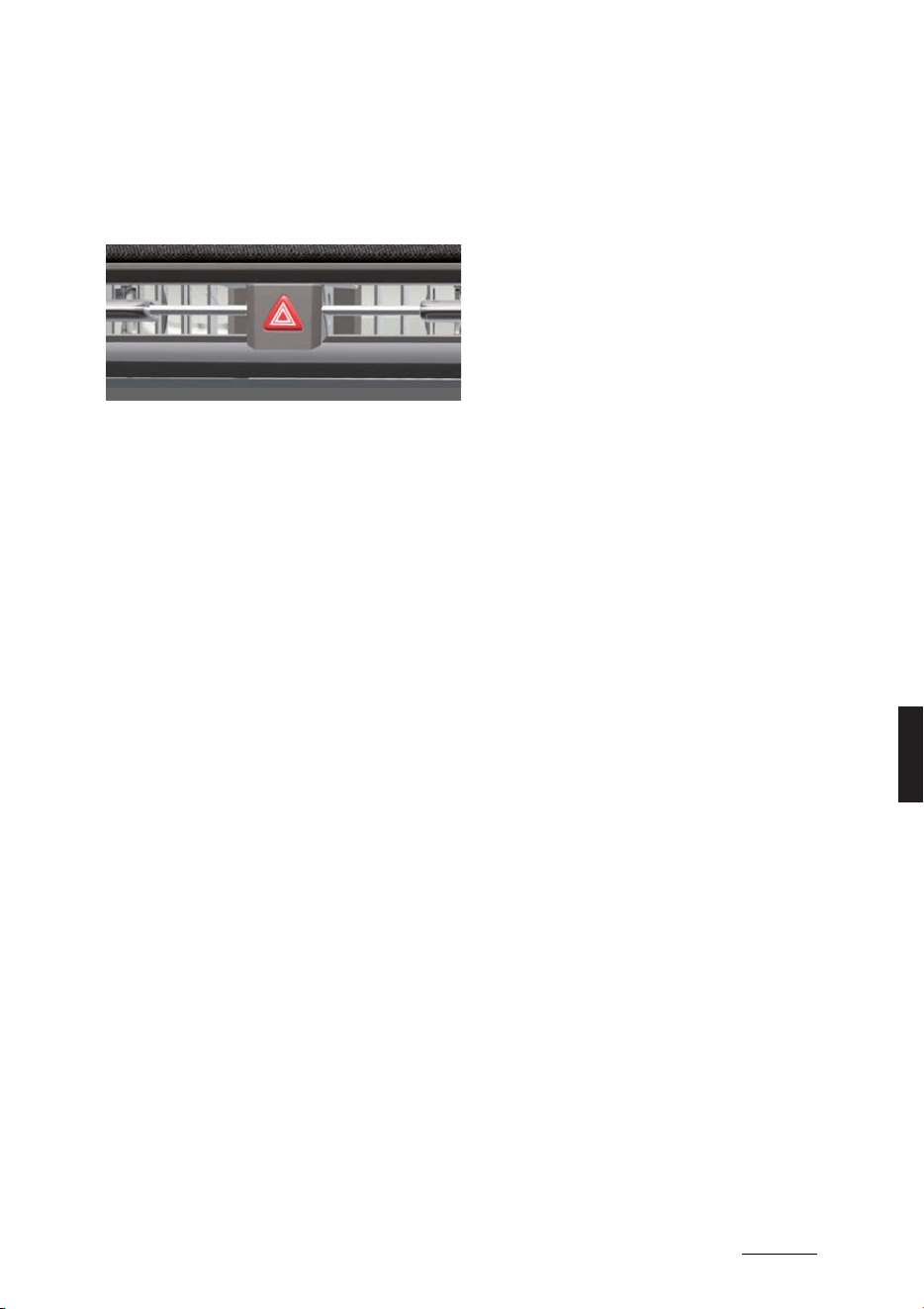
3
7
7
What to do in an emergency Road warning
What to do in an emergency
Road warning
Hazard warning flasher
Condition(s)
僅 When an emergency situation occurs
while driving
僅 Parking by the edge of the roadway
Operation
僅 Push the hazard warning flasher
switch.
In the event of an emergency
while driving
If the vehicle stalls while driving
Operation
1. Reduce your speed and keep straight.
2. Stop the vehicle in a safe place.
3. Turn the hazard warning flasher on.
4. Restart the vehicle.
If the vehicle still does not start, contact
a professional workshop or seek other
qualified assistance. Kia recommends to
call an authorized Kia dealer/service
partner.
If the vehicle stalls at a crossroad
or crossing
Operation
1. Shift to N (Neutral).
2. Push the vehicle to a safe place.
If you have a flat tire while driv
-
ing
Operation
1. Reduce your speed slowly and keep
straight.
2. Stop the vehicle in a safe, level place
away from traffic.
3. Turn the hazard warning flasher on.
4. Set the parking brake.
5. Shift to P (Park).
6. Have all passengers get out of the
vehicle and move away from traffic.
Refer to "If you have a flat tire (with Tire
Mobility Kit)" on page 7-10.
OCV061005L
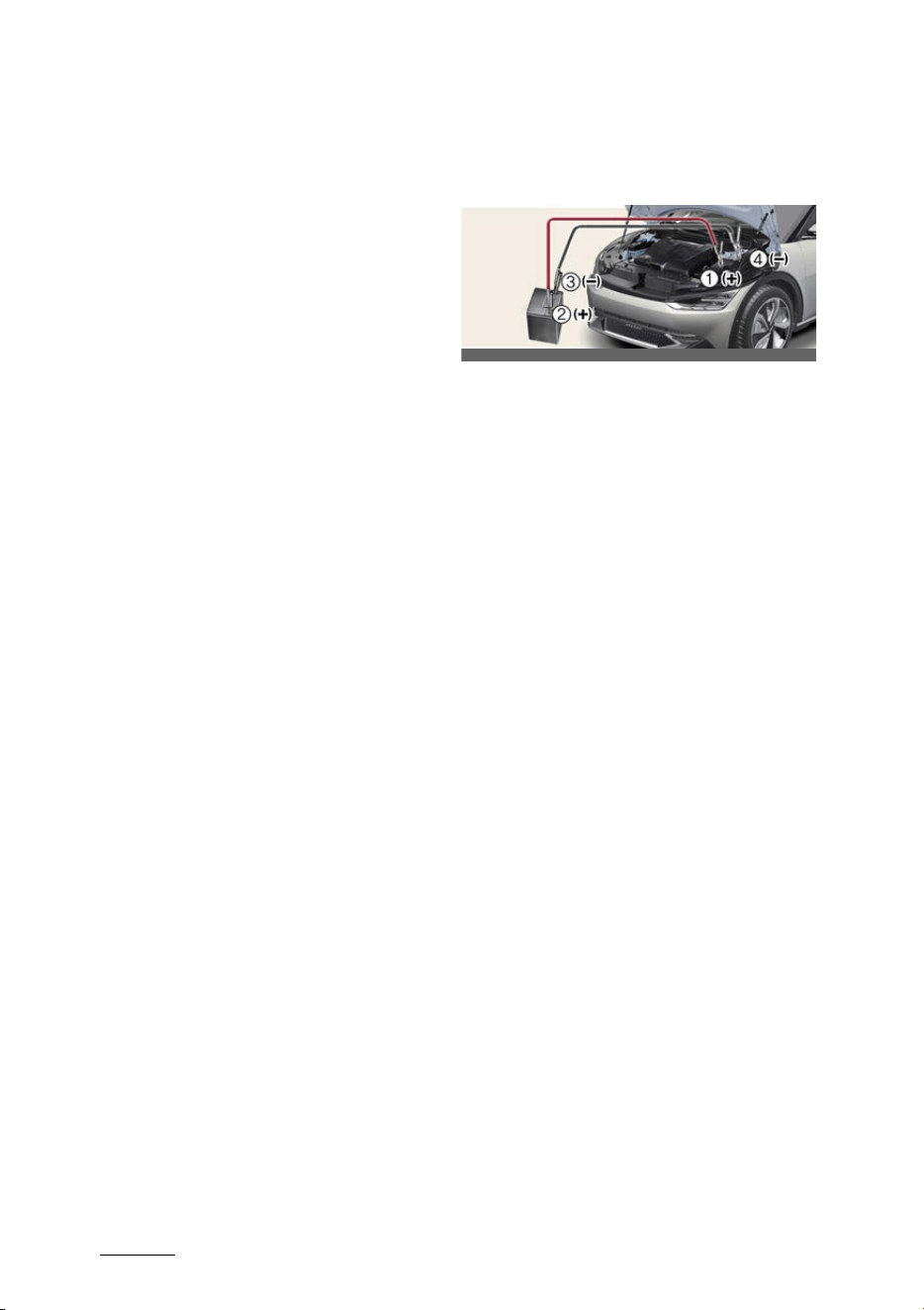
What to do in an emergency
47
If the vehicle will not start
If the vehicle will not start
Confirm the EV battery is not low on the
charge gauge.
僅 Be sure P (Park) gear position is
selected. The vehicle starts only when
P (Park) gear position is selected.
僅 Check the 12-volt battery connections
to be sure they are clean and tight.
僅 Turn on the interior light. If the light
dims or goes out when you operate
the starter, the 12V battery is drained.
Do not push or pull the vehicle to start it.
This could cause damage to your vehi
-
cle.
Emergency starting
Jump-starting (12V battery)
Condition(s)
僅 When the vehicle will not start due to
low battery power
Operation
1. Connect the jumper cables as shown.
僅 Positive (+) terminal of the flat bat
-
tery (1) and the booster battery (2).
僅 Negative (-) terminal of the flat bat
-
tery (3) and the grounding point
(4).
2. Start the vehicle with the booster bat
-
tery for several minutes.
3. Try to start the vehicle with the flat
battery again.
4. If the vehicle starts, disconnect the
jumper cables as following:
僅 Negative (-) terminal of the booster
battery (3).
僅 Positive (+) terminal of the booster
battery (2)
僅 Flat battery (1).
If the vehicle still does not start, contact
a professional workshop or seek other
qualified assistance. Kia recommends to
call an authorized Kia dealer/service
partner.
OCV061006L

5
7
7
What to do in an emergency Emergency starting
WARNING
僅 Keep all flames or sparks away from
the battery. The battery produces
hydrogen gas which may explode if
exposed to flame or sparks. If these
instructions are not followed exactly,
serious personal injury and damage to
the vehicle may occur! If you are not
sure how to follow this procedure,
seek qualified assistance. Automobile
batteries contain sulfuric acid. This is
poisonous and highly corrosive. When
jump starting, wear protective glasses
and be careful not to get acid on your
-
self, your clothing or on the vehicle.
僅 Do not attempt to jump start the vehi
-
cle if the discharged battery is frozen
or if the electrolyte level is low; the
battery may rupture or explode.
僅 Do not allow the (+) and (-) jumper
cables to touch. It may cause sparks.
僅 Never attempt to check the electrolyte
level of the battery as this may cause
the battery to rupture or explode
causing serious injury.
僅 The battery may rupture or explode
when you jump start with a low or fro
-
zen battery.
僅 The electrical starting system works
with high voltage. NEVER touch these
components with the
READY
indica
-
tor ON or when the EV button is in the
ON position.
CAUTION
Use only a 12-volt jumper system. You
can damage other electrical parts
beyond repair by use of a 24- volt power
supply (either two 12-volt batteries in
series or a 24-volt motor generator set).
NOTICE
Do not connect the jumper cable from
the negative terminal of the booster bat
-
tery to the negative terminal of the dis
-
charged battery. This can cause the
discharged battery to overheat and
crack, releasing battery acid. Make sure
to connect one end of the jumper cable
to the negative terminal of the booster
battery, and the other end to a metallic
point, far away from the battery.
Push-starting
Your vehicle equipped with reduction
gear should not be push-started.
WARNING
Never tow a vehicle to start it. When the
vehicle starts, the vehicle can suddenly
surge forward and could cause a colli
-
sion with the tow vehicle.
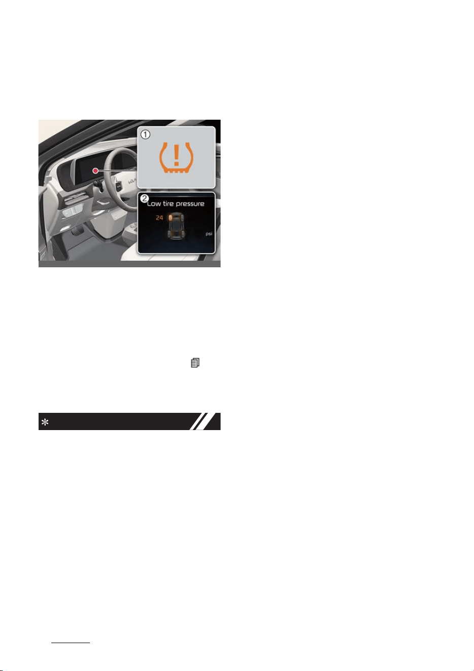
What to do in an emergency
67
Tire Pressure Monitoring System (TPMS)
Tire Pressure Monitoring Sys
-
tem (TPMS)
Checking the tire pressure
1
Low tire pressure telltale/Tire Pres
-
sure Monitoring System (TPMS) mal
-
function indicator
2
Low tire pressure position telltale
Operation
1. Press the cluster menu button ( ) on
the steering wheel.
2. Select 'Information mode' from the
LCD display modes.
INFORMATION
僅 You can change the tire pressure unit
in the user settings mode on the clus
-
ter.
- psi, kpa, bar (Refer to "LCD display
modes" on page 5-47.)
僅 Each tire should be checked monthly
when cold and inflated to the inflation
pressure recommended by the vehi
-
cle manufacturer on the vehicle plac
-
ard or tire inflation pressure label.
(If your vehicle has tires of a different
size than the size indicated on the
vehicle placard or tire inflation pres
-
sure label, you should determine the
proper tire inflation pressure for those
tires.)
As an added safety feature, your vehi
-
cle has been equipped with a tire
pressure monitoring system (TPMS)
that illuminates a low tire pressure
telltale when one or more of your tires
is significantly under-inflated. Accord
-
ingly, when the low tire pressure tell
-
tale illuminates, you should stop and
check your tires as soon as possible,
and inflate them to the proper pres
-
sure. Driving on a significantly under-
inflated tire causes the tire to over
-
heat and can lead to tire failure.
Under-inflation also reduces electric
energy efficiency and tire tread life,
and may affect the vehicle's handling
and stopping ability.
Note that the TPMS is not a substitute
for proper tire maintenance, and it is
the driver's responsibility to maintain
correct tire pressure, even if under-
inflation has not reached the level to
trigger illumination of the TPMS low
tire pressure telltale.
Your vehicle has also been equipped
with a TPMS malfunction indicator to
indicate when the system is not oper
-
ating properly. The TPMS malfunction
indicator is combined with the low tire
pressure telltale. When the system
detects a malfunction, the telltale will
flash for approximately 1 minute and
then remain continuously illuminated.
This sequence will continue upon sub
-
sequent vehicle start-ups as long as
the malfunction exists. When the
TPMS malfunction indicator remains
illuminated after blinking for approxi
-
mately 1 minute, the system may not
be able to detect or signal low tire
pressure as intended.
OCV061007L_2
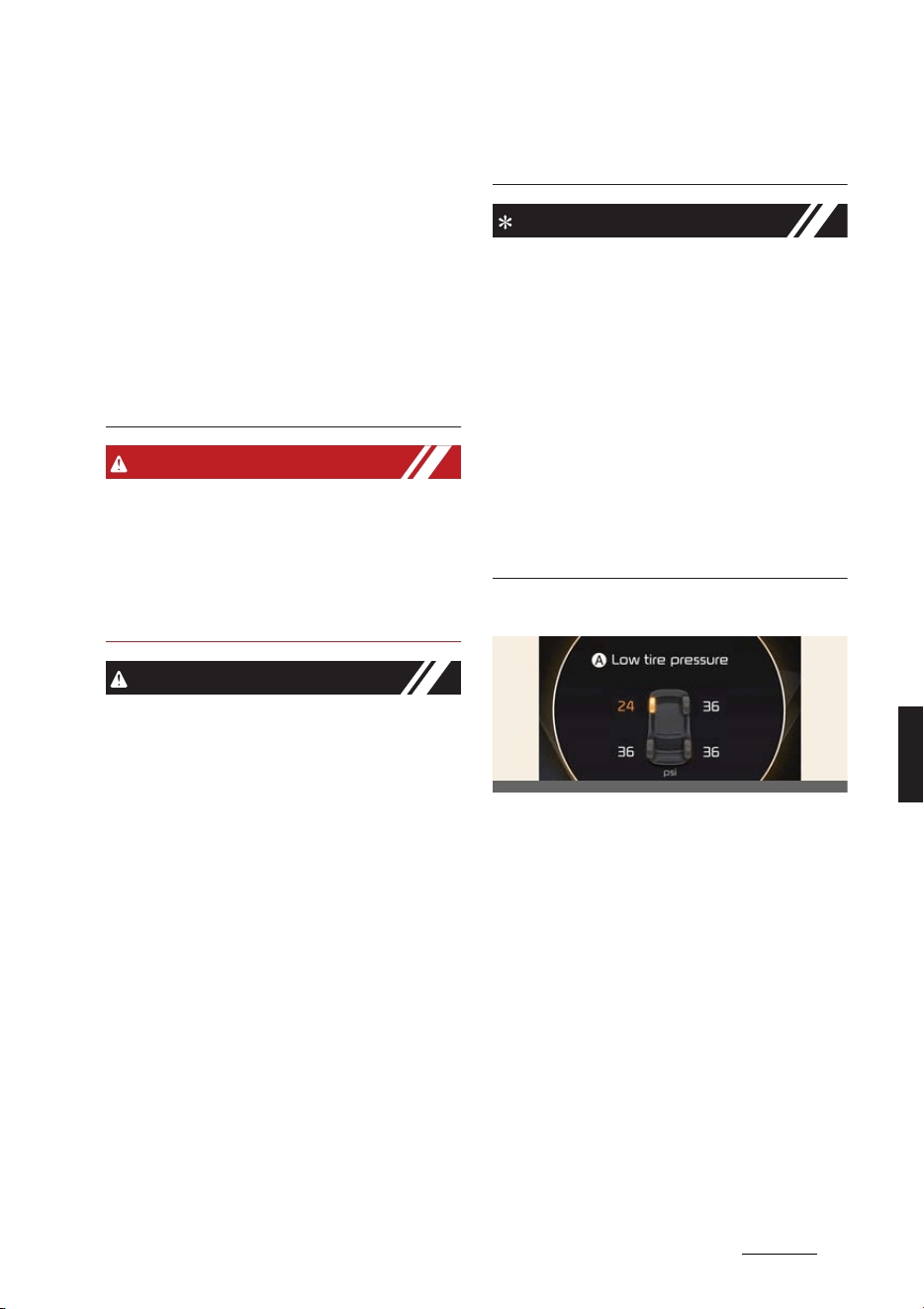
7
7
7
What to do in an emergency Tire Pressure Monitoring System (TPMS)
TPMS malfunctions may occur for a
variety of reasons, including the
installation of replacement or alter
-
nate tires or wheels on the vehicle
that prevent the TPMS from function
-
ing properly. Always check the TPMS
malfunction telltale after replacing
one or more tires or wheels on your
vehicle to ensure that the replace
-
ment or alternate tires and wheels
allow the TPMS to continue to func
-
tion properly.
WARNING
Significantly low tire pressure makes the
vehicle unstable and can contribute to
loss of vehicle control and increased
braking distances.
Continued driving on low pressure tires
can cause the tires to overheat and fail.
CAUTION
僅 In winter or cold weather, the low tire
pressure telltale may illuminate if the
tire pressure was adjusted to the rec
-
ommended tire inflation pressure in
warm weather. It does not mean your
TPMS is malfunctioning because the
decreased temperature leads to a
lowering of tire pressure.
僅 When you drive your vehicle from a
warm area to a cold area or from a
cold area to a warm area, or the out
-
side temperature is higher or lower,
you should check the tire inflation
pressure and adjust the tires to the
recommended tire inflation pressure.
僅 When filling tires with more air, condi
-
tions to turn off the low tire pressure
telltale may not be met. This is
because a tire inflator has a margin of
error in performance. The low tire
pressure telltale will be turned off if
the tire pressure is above the recom
-
mended tire inflation pressure.
NOTICE
If any of the below happens, have the
system checked by a professional work
-
shop. Kia recommends visiting an autho
-
rized Kia dealer/service partner.
1. The low tire pressure telltale/TPMS
malfunction indicator do not illumi
-
nate for 3 seconds when the vehicle is
in ON position or vehicle is running.
2. The TPMS malfunction indicator
remains illuminated after blinking for
approximately 1 minute.
3. The Low tire pressure position telltale
remains illuminated.
When the telltale lights up
A:
Low tire pressure
Condition(s)
僅 One or more of the tires is signifi
-
cantly under-inflated.
Operation
僅 The corresponding position light will
light up to indicate which tire is signifi
-
cantly under-inflated.
僅 Reduce your speed, avoid hard cor
-
nering, and anticipate increased stop
-
ping distances.
僅 Stop and check the tires as soon as
possible.
OCV041126L

What to do in an emergency
87
Tire Pressure Monitoring System (TPMS)
僅 Inflate the tires to the specified pres
-
sure.
僅 Replace the underinflated tire with a
spare tire if this is not possible.
Tire Pressure Monitoring System
(TPMS) malfunction indicator
Conditions
僅 Blinks for approximately 1 minute
- When there is a problem with the
Tire Pressure Monitoring System.
Contact a professional workshop or seek
other qualified assistance. Kia recom
-
mends to call an authorized Kia dealer/
service partner.
CAUTION
僅 The TPMS malfunction indicator may
blink for approximately 1 minute and
then remain continuously illuminated
if the vehicle is moving around electric
power supply cables or radios trans
-
mitter such as at police stations, gov
-
ernment and public offices,
broadcasting stations, military instal
-
lations, airports, or transmitting tow
-
ers, etc. This can interfere with normal
operation of the Tire Pressure Moni
-
toring System (TPMS).
僅 The TPMS malfunction indicator may
blink for approximately 1 minute and
then remain continuously illuminated
if snow chains are used or some sepa
-
rate electronic devices such as note
-
book computer, mobile charger,
remote starter or navigation etc., are
used in the vehicle.
This can interfere with normal opera
-
tion of the Tire Pressure Monitoring
System (TPMS).
NOTICE
If there is a malfunction with the TPMS,
the low tire pressure position telltale will
not be displayed even though the vehi
-
cle has an underinflated tire.
Changing a tire equipped with
Tire Pressure Monitoring System
(TPMS)
Contact a professional workshop or seek
other qualified assistance. Kia recom
-
mends to call an authorized Kia dealer/
service partner.
INFORMATION
You may not be able to identify a low tire
by simply looking at it. Always use a
good quality tire pressure gauge to mea
-
sure the tire's inflation pressure. Note
that a tire that is hot (from being driven)
will have a higher pressure measure
-
ment than a tire that is cold (from sitting
stationary for at least 3 hours and driven
less than 1 mile (1.6 km) during that 3
hour period).
Allow the tire to cool before measuring
the inflation pressure. Always be sure
the tire is cold before inflating to the rec
-
ommended pressure.
A cold tire means the vehicle has been
sitting for 3 hours and driven for less
than 1 mile (1.6 km) in that 3 hour period.
WARNING
僅 The TPMS cannot alert you to severe
and sudden tire damage caused by
external factors such as nails or road
debris.
僅 If you feel any vehicle instability,
immediately take your foot off the
accelerator, apply the brakes gradu
-

9
7
7
What to do in an emergency Tire Pressure Monitoring System (TPMS)
ally and with light force, and slowly
move to a safe position off the road.
僅 Tampering with, modifying, or dis
-
abling the Tire Pressure Monitoring
System (TPMS) components may
interfere with the system's ability to
warn the driver of low tire pressure
conditions and/or TPMS malfunctions.
Tampering with, modifying, or dis
-
abling the Tire Pressure Monitoring
System (TPMS) components may void
the warranty for that portion of the
vehicle.
WARNING
For Europe
僅 Do not modify the vehicle, it may
interfere with the TPMS function.
僅 The wheels on the market do not have
a TPMS sensor. For your safety, use
parts for replacement from a profes
-
sional workshop. Kia recommends vis
-
iting an authorized Kia dealer/service
partner.
僅 If you use the wheels on the market,
use a TPMS sensor approved by an
authorized Kia dealer.
If your vehicle is not equipped with a
TPMS sensor or TPMS does not work
properly, you may fail the periodic
vehicle inspection conducted in your
country.
僅 All vehicles sold in the EUROPE mar
-
ket during below period must be
equipped with TPMS.
- New model vehicle: Nov. 1, 2012 ~
- Current model vehicle: Nov. 1,
2014~ (Based on vehicle registra
-
tions)
CAUTION
We recommend that you use the sealant
approved by Kia if your vehicle is
equipped with a Tire Pressure Monitor
-
ing System. The liquid sealant can dam
-
age the tire pressure sensors.
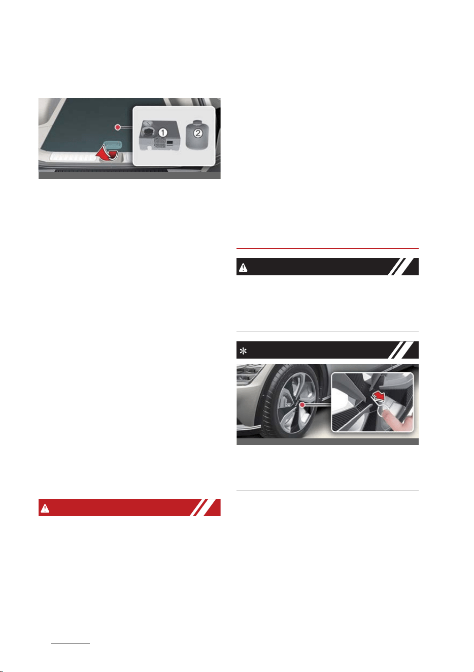
What to do in an emergency
107
If you have a flat tire (with Tire Mobility Kit)
If you have a flat tire (with Tire
Mobility Kit)
1
Compressor
2
Sealant bottle
The Tire Mobility Kit is not designed or
intended as a permanent tire repair
method and is to be used for one tire
only.
The system with compressor and sealing
compound seals most tire punctures
caused by nails or similar objects and
reinflates the tire. However, larger punc
-
tures or sidewall damage cannot be
sealed completely.
After ensuring that the tire is properly
sealed, you can drive cautiously on the
tire (for a distance of up to 200 km (120
miles)) at maximum speed of 80 km/h
(50 mph) in order to reach a service sta
-
tion or a tire dealer to have the tire
replaced.
Avoid abrupt steering or other driving
maneuvers if the vehicle is heavily
loaded or if a trailer is in use.
Refer to "Safe use of the Tire Mobility
Kit" on page 7-14.
WARNING
僅 Do not use the Tire Mobility Kit to
repair punctures in the tire walls. This
can result in an accident due to tire
failure.
僅 Have your tire repaired as soon as
possible. The tire may loose air pres
-
sure at any time after inflating with
the Tire Mobility Kit.
僅 Do not use the TMK if a tire is severely
damaged by driving run flat or with
insufficient air pressure. Only punc
-
tured areas located within the tread
region of the tire can be sealed using
the TMK.
僅 Do not use the Tire sealant after the
sealant has expired (i.e. past the expi
-
ration date on the sealant container).
This can increase the risk of tire fail
-
ure.
僅 Keep the sealant out of reach of chil
-
dren, avoid sealant contact with eyes
and do not swallow the sealant.
CAUTION
When two or more tires are flat, do not
use the tire mobility kit because the sup
-
ported one sealant of Tire Mobility Kit is
only used for one flat tire.
NOTICE
For 20 inch wheel, take out the remover
tool in the Tire Mobility Kit. Insert the tool
to the hole and pull out the wheel cover.
OCV061009L
OCV041414L
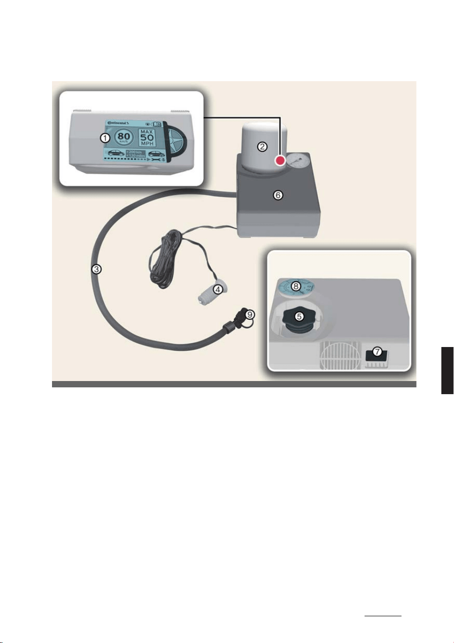
11
7
7
What to do in an emergency If you have a flat tire (with Tire Mobility Kit)
Components of the Tire Mobility Kit
* Connectors, cable and connection hose are stored in the compressor housing.
* Strictly follow the specified sequence, otherwise the sealant may escape under high
pressure.
1
Speed restriction label
2
Sealant bottle
3
Sealant bottle filling hose
4
Power outlet connector
5
Sealant bottle holder
6
Compressor
7
ON/OFF switch
8
Tire inflation pressure gauge
9
Tire inflation pressure valve
OCV061008_2
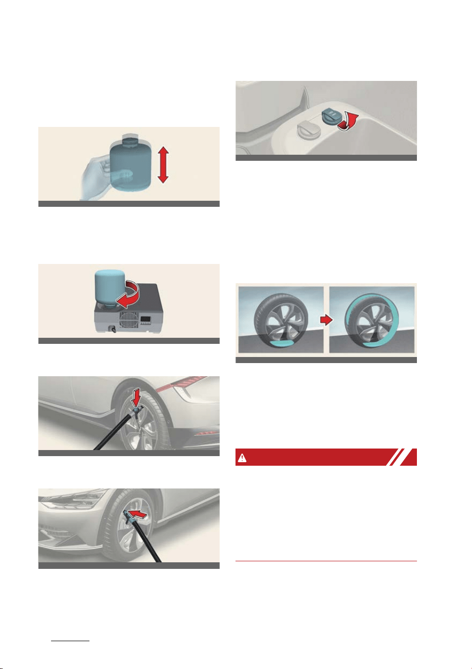
What to do in an emergency
127
If you have a flat tire (with Tire Mobility Kit)
Using the Tire Mobility Kit
Operation
1. Shake the sealant bottle.
2. Remove the sealant bottle cap and
sealant bottle holder cap and screw
the bottle onto the sealant bottle
holder.
3. Make sure the compressor valve on
the filling hose is locked.
4. Unscrew the valve cap and screw the
filling hose onto the tire valve.
5. Make sure the compressor is turned
off.
6. Connect the power outlet connector.
7. Start the vehicle.
8. Turn the compressor on and let it run
for approximately 5~7 minutes to fill
the sealant up to the proper pressure.
9. Turn the compressor off.
10.Detach the filling hose from the tire
valve.
Distributing the sealant
Operation
僅 Immediately drive approximately
7~10 km (4~6 miles, or approximately
10 minutes) to distribute the tire seal
-
ant evenly.
WARNING
僅 Do not leave your vehicle running in a
poorly ventilated area for extended
periods of time. Carbon monoxide
poisoning and suffocation can occur.
僅 If the tire pressure is below 26 psi(180
kPa), do not drive the vehicle. The tire
may cause accident.
OCV061010L
OCV061011L
OCV061014L
OCV061015L
OCV061012L
OCV061013L_2
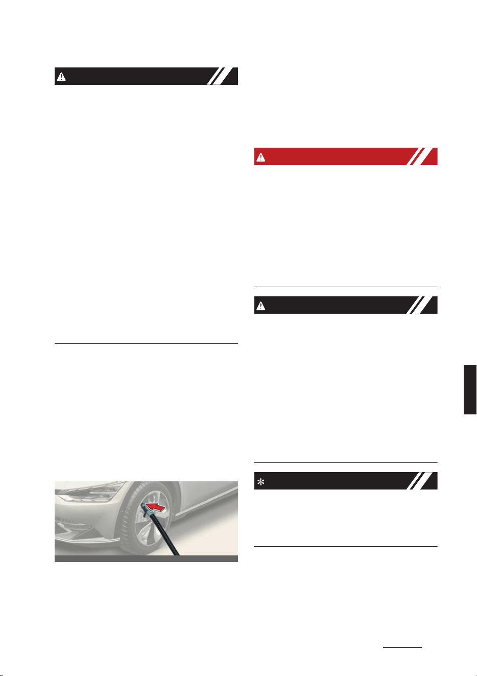
13
7
7
What to do in an emergency If you have a flat tire (with Tire Mobility Kit)
CAUTION
僅 Securely install the sealant filling hose
to the valve. If not, sealant may flow
backward, possibly clogging the filling
hose.
僅 Do not exceed a speed of 80 km/h
(50 mph). If possible, do not fall below
a speed of 20 km/h (12 mph). While
driving, if you experience any unusual
vibration, ride disturbance or noise,
reduce your speed and drive with
caution until you can safely pull off of
the side of the road. Call for road side
service or towing. When you use the
Tire Mobility Kit, the wheel may be
stained by sealant. Therefore, remove
the wheel stained by sealant and have
the vehicle inspected at a professional
workshop. Kia recommends visiting
an authorized Kia dealer/service part
-
ner.
Checking tire inflation pressure
Operation
1. After driving approximately 7~10 km
(4~6 miles, or approximately 10 min
-
utes), stop the vehicle in a safe, level
place.
2. Connect the filling hose directly to the
tire valve.
3. Connect the power outlet connector.
4. Adjust the tire inflation pressure to the
specified value.
僅 Turn the compressor on to increase
the inflation pressure. Turn the
compressor off briefly to check the
current inflation pressure.
僅 Turn the compressor valve to
reduce the inflation pressure.
WARNING
僅 Do not let the compressor run for
more than 10 minutes, otherwise the
device will overheat and may be dam
-
aged.
僅 The tire inflation pressure must be
inflated to the proper pressure (Refer
to "Tires and wheels" on page 9-6). If it
is not, do not continue driving. Call for
road side service or towing.
CAUTION
僅 If the inflation pressure is not main
-
tained, drive the vehicle a second
time, refer to "Distributing the sealant"
on page 7-12. Then repeat steps 1 to 4.
僅 Use of the TMK may be ineffectual for
tire damage larger than approxi
-
mately 4 mm (0.16 inches).
僅 We recommend that you contact a
professional workshop if the tire can
-
not be made roadworthy with the Tire
Mobility Kit.
NOTICE
When reinstalling the repaired or
replaced tire and wheel on the vehicle,
tighten the wheel lug nut to 11~13 kgf·m
(79~94 lbf·ft).
OCV061015L

What to do in an emergency
147
If you have a flat tire (with Tire Mobility Kit)
Safe use of the Tire Mobility Kit
僅 Stop the vehicle in a safe, level place
away from traffic.
僅 Set the parking brake.
僅 Only use the Tire Mobility Kit for seal
-
ing/inflating passenger vehicle tires.
僅Do not remove any foreign objects
from the tire.
僅 Read the precautionary advice
printed on the sealant bottle before
using the Tire Mobility Kit.
僅 Leave the vehicle running. Operating
the Tire Mobility Kit may drain the
battery.
僅 Never leave the Tire Mobility Kit unat
-
tended while it is being used.
僅 Do not leave the compressor running
for more than approximately 10 min
-
utes at a time or it may overheat.
僅 Do not use the Tire Mobility Kit if the
ambient temperature is below -30 °C
(-22 °F).
僅 Do not use the Tire Mobility Kit if the
tire and wheel are damaged.
Technical Data
僅 System voltage: DC 12 V
僅 Working voltage: DC 12 V
僅 Amperage rating: max. 15 A
僅 Suitable temperatures: -30 to 70 °C (-
22 to 158 °F)
僅 Max. working pressure: 7 bar (101 psi)
僅Size
- Compressor: 150 x 130 x 60 mm
(5.9 x 5.1 x 2.4 inches)
- Sealant bottle: 115.3 x 87.3 ø mm
(4.5 x 3.4 ø inches)
- Compressor weight: 620 g (1.36
lbs.)
- Sealant volume: 400 ml (24.4 cu.
in)
* Sealant and spare parts can be
obtained and replaced at an autho
-
rized vehicle or tire dealer. Empty seal
-
ant bottles may be disposed of at
home. Liquid residue from the sealant
should be disposed of by your vehicle
or tire dealer or in accordance with
local waste disposal regulations.
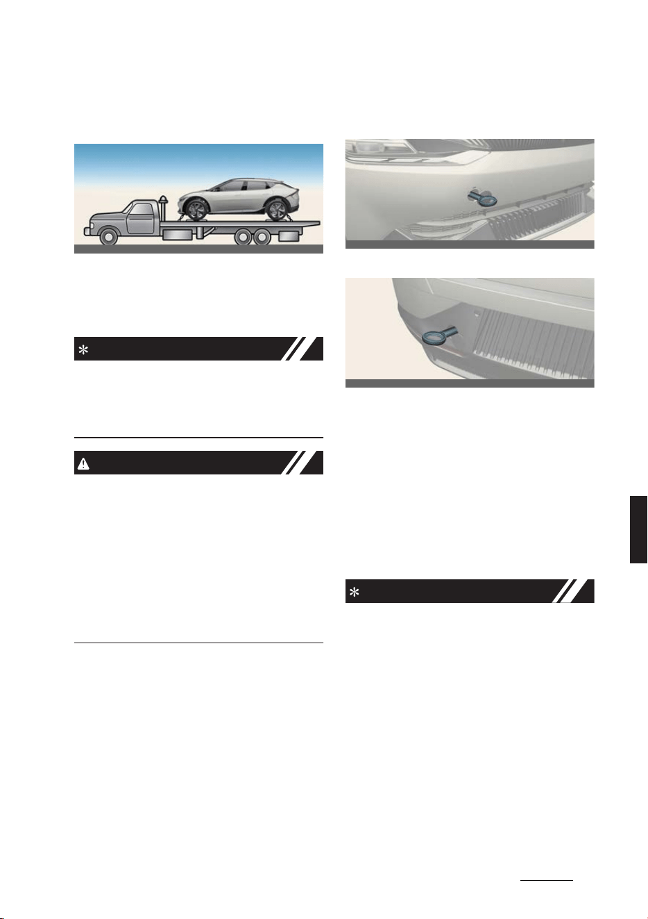
15
7
7
What to do in an emergency Towing
Towing
Towing service
Operation
僅 Tow the vehicle with a flatbed equip
-
ment with all wheels off the ground.
INFORMATION
If emergency towing is necessary, we
recommend having it done by an autho
-
rized Kia dealer or a commercial tow-
truck service.
CAUTION
僅 Do not tow the vehicle forwards with
the rear wheels on the ground as this
may cause damage to the vehicle.
僅 Do not tow with sling-type equipment.
Use wheel lift or flatbed equipment.
僅 The 4WD vehicle should never be
towed with the wheels on the ground.
This can cause serious damage to the
vehicle or the 4WD system.
Emergency towing
Front
Rear
Operation
1. Remove the hole cover by pressing
the lower part of the cover on the
bumper.
2. Install the towing hook by screwing it
clockwise into the hole until it is fully
secured.
3. After use, remove the towing hook
and reinstall the cover.
INFORMATION
Towing in this manner may be done only
on hard-surfaced roads for a short dis
-
tance and at low speed. Also, the wheels,
axles, power train, steering and brakes
must all be in good condition.
僅 Do not use the tow hooks to pull a
vehicle out of mud, sand or other con
-
ditions from which the vehicle cannot
be driven out under its own power.
僅 Avoid towing a vehicle heavier than
the vehicle doing the towing.
僅 The drivers of both vehicles should
communicate with each other fre
-
quently.
OCV061024L
OCV061018L
OCV061017L

What to do in an emergency
167
Towing
僅 Before emergency towing, check if
the hook is not broken or damaged.
僅 Fasten the towing cable or chain
securely to the hook.
僅 Do not jerk the hook. Apply it steadily
and with even force.
僅 To avoid damaging the hook, do not
pull from the side or at a vertical
angle. Always pull straight ahead.
僅 Press the EV button to the ACC posi
-
tion so the steering wheel is not
locked.
僅 Shift the gear to N (Neutral).
僅 Release the parking bake.
僅 To avoid serious damage to the gear,
limit the vehicle speed to 15 km/h (10
mph) and drive less than 1.5 km (1
mile) when towing.
僅 Press the brake pedal with more force
than normal since you will have
reduced brake performance.
僅 More steering effort will be required
because the power steering system
will be disabled.
僅 If you are driving down a long hill, the
brakes may overheat and brake per
-
formance will be reduced. Stop often
and let the brakes cool off.
WARNING
Use extreme caution when towing the
vehicle.
僅 Avoid sudden starts or erratic driving
maneuvers which would place exces
-
sive stress on the emergency towing
hook and towing cable or chain. The
hook and towing cable or chain may
break and cause serious injury or
damage.
僅 If the disabled vehicle is unable to be
moved, do not forcibly continue the
towing. We recommend that you con
-
tact an authorized Kia dealer or a
commercial tow truck service for
assistance.
僅 Tow the vehicle as straight ahead as
possible.
僅 Keep away from the vehicle during
towing.
CAUTION
僅 Attach a towing strap to the tow hook.
僅 Using a portion of the vehicle other
than the tow hooks for towing may
damage the body of your vehicle.
僅 Use only a cable or chain specifically
intended for use in towing vehicles.
Securely fasten the cable or chain to
the towing hook provided.
僅 Accelerate or decelerate the vehicle in
a slow and gradual manner while
maintaining tension on the tow rope
or chain to start or drive the vehicle,
otherwise tow hooks and the vehicle
may be damaged.

17
7
7
What to do in an emergency Emergency commodity
Emergency commodity (if
equipped)
Fire extinguisher
If there is small fire and you know how to
use the fire extinguisher, follow these
steps carefully.
1. Pull out the safety pin at the top of the
extinguisher that keeps the handle
from being accidentally pressed.
2. Aim the nozzle towards the base of
the fire.
3. Stand approximately 2.5 m (8 ft) away
from the fire and squeeze the handle
to discharge the extinguisher. If you
release the handle, the discharge will
stop.
4. Sweep the nozzle back and for that
the base of the fire. After the fire
appears to be out, watch carefully
since it may re-ignite.
First-aid kit
Scissors, bandages, adhesive tape, etc.
are provided in the kit.
Reflector triangle
Place the Reflector triangle on the road
to warn oncoming vehicles.
Tire pressure gauge
1. Unscrew the inflation valve cap.
2. Press and hold the gauge against the
tire valve.
3. Pressing firmly will activate the gauge
and avoid too much leak.
4. Adjust the inflation of the tires to the
specified pressure, as necessary.
5. Reinstall the inflation valve cap.
WARNING
僅 When an accident occur, park the
vehicle to a safe place. To avoid the
leak of electricity in high voltage bat
-
tery, turn the vehicle off and pull the
yellow label in the high voltage bat
-
tery switch to shut down the high volt
-
age battery. Also, disconnect the
auxiliary battery(12V) cable to shut
-
down. Be sure to disconnect both
(+)cable and (-) cable.
僅 Do not touch the exposed electric
wires. Do not touch high voltage wires
(orange), connectors and other elec
-
tric components.
僅 When an accident occur, the lethal
gas and fluid from damaged high
voltage battery can be leaked. Be
aware not to touch or exposed to the
gas and fluid. When flammable or poi
-
son gas leak inside the vehicle, open
windows and evacuate to a safe place.
When leaked fluid comes in contact
with your eyes, flush your eyes with
clean water. When the fluid contacts
with your skin, wash it with salt water.
Get immediate medical attention
afterward.
僅 When the vehicle is flooded, immedi
-
ately turn the vehicle off and evacuate
to a safe place. For your safety we
recommend to call the fire station and
or visit an authorized Kia dealer/ser
-
vice partner.
僅 When the fire spread to the high volt
-
age battery, the additional fire may
occur. In this situation, be sure to
accompany a fire truck when the
vehicle is being towed.
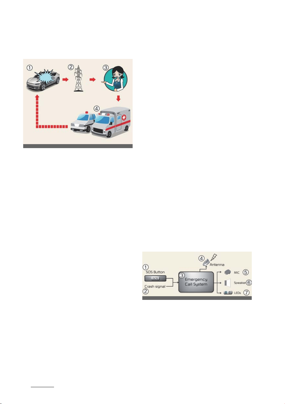
What to do in an emergency
187
Pan-European eCall system
Pan-European eCall system (if
equipped)
1
Road accident
2
Wireless network
3
Public Safety Answering Point (PSAP)
4
Rescue
The car is equipped with a device
*1
con
-
nected with the Pan-European eCall sys
-
tem for making emergency call to
response teams. The Pan- European
eCall system is an automatic emergency
call service made in event of a traffic
accident or other
*2
accidents on the
roads of Europe. (only in countries with
regulation on this system)
The system allows contacting with an
officer of the single duty dispatch ser
-
vice in case of accidents on the roads of
Europe. (only in countries with regula
-
tion on this system)
The Pan-European eCall system given
conditions, stated in the Owner's Manual
as well as Warranty and Service book
transmits data to the Public Safety
Answering Point (PSAP) including such
information as vehicle location, vehicle
type, VIN (vehicle identification number
of the car).
Once the data which is stored in the
Pan-European eCall system is delivered
to the rescue center to assist the driver
and passengers with proper rescue
operations, the data will be deleted after
rescue operation is completed.
*1. Pan-European eCall device in the
Owner's Manual means equipment,
installed in the car, which provides con
-
nection with the Pan-European eCall
system.
*2. "Other accidents" mean any accidents
on the roads of Europe (only in countries
with regulation on this system) resulted
in injured people and/or necessity of
provision of assistance. In case of regis
-
tration of any accident, it is necessary to
stop a vehicle, press button SOS (loca
-
tion of the button is specified on the pic
-
ture in the chapter "Pan-European eCall
(IF EQUIPPED)") of the Owner's Manual.
When making a call, the system gathers
information about the car (from which a
call was made), after which connects the
car with an officer of the Public Safety
Answering Point (PSAP) to tell about the
reason of the emergency call.
Description of the ecall in-vehicle
system
1
SOS Button
2
Crash signal
3
Emergency Call System
4
Antenna
5
MIC
6
Speaker
7
LEDs
OCV061019L
OSG2PH062013L

19
7
7
What to do in an emergency Pan-European eCall system
Overview of the 112-based eCall in-vehi
-
cle system, its operation and functional
-
ities: refer to this section. The 112-based
eCall service is a public service of gen
-
eral interest and is accessible free of
charge.
The 112-based eCall in-vehicle system is
activated by default. It is activated auto
-
matically by means of in- vehicle sensors
in the event of a severe accident.
It will also be triggered automatically
when the vehicle is equipped with a TPS
system which does not function in the
event of a severe accident.
The 112-based eCall in-vehicle system
can also be triggered manually, if
needed. Instructions for manual activa
-
tion of the system: refer to this section.
In the event of a critical system failure
that would disable the 112-based eCall
in-vehicle system, the following warning
will be given to the occupants of the
vehicle: refer to this section.
Information on data processing
Any processing of personal data through
the 112-based eCall in-vehicle system
shall comply with the personal data pro
-
tection rules provided for in Directives
95/46/EC (1) and 2002/58/EC (2) of the
European Parliament and of the Council,
and in particular, shall be based on the
necessity to protect the vital interests of
the individuals in accordance with Article
7(d) of Directive 95/46/EC (3).
Processing of such data is strictly limited
to the purpose of handling the emer
-
gency eCall to the single European
emergency number 112.
Types of data and its recipients
The 112-based eCall in-vehicle system
may collect and process only the follow
-
ing data:
僅 Vehicle Identification Number
僅 Vehicle type (passenger vehicle or
light commercial vehicle)
僅 Vehicle propulsion storage type (gas
-
oline/diesel/CNG/LPG/electric/hydro
-
gen)
僅 Vehicle recent locations and direction
of travel
僅 Log file of the automatic activation of
the system and its timestamp
僅 Any additional data (if applicable): Not
applicable
Recipients of data processed by the 112-
based eCall in-vehicle system are the
relevant public safety answering points
designated by the respective public
authorities of the country on which terri
-
tory they are located, to first receive and
handle eCalls to the single European
emergency number 112. Additional infor
-
mation (if available): Not applicable
1. Directive 95/46/EC of the European
Parliament and of the Council of 24
October 1995 on the protection of
individuals with regard to the process
-
ing of personal data and on the free
movement of such data (OJ L 281,
23.11.1995, p. 31).
2. Directive 2002/58/EC of the Euro
-
pean Parliament and of the Council of
12 July 2002 concerning the process
-
ing of personal data and the protec
-
tion of privacy in the electronic
communications sector (Directive on
privacy and electronic communica
-
tions) (OJ L 201, 31.7.2002, p. 37).
3. Directive 95/46/EC is repealed by
Regulation (EU) 2016/679 of the Euro
-
pean Parliament and of the Council of
27 April 2016 on the protection of nat
-
ural persons with regard to the pro
-
cessing of personal data and on the
free movement of such data (General
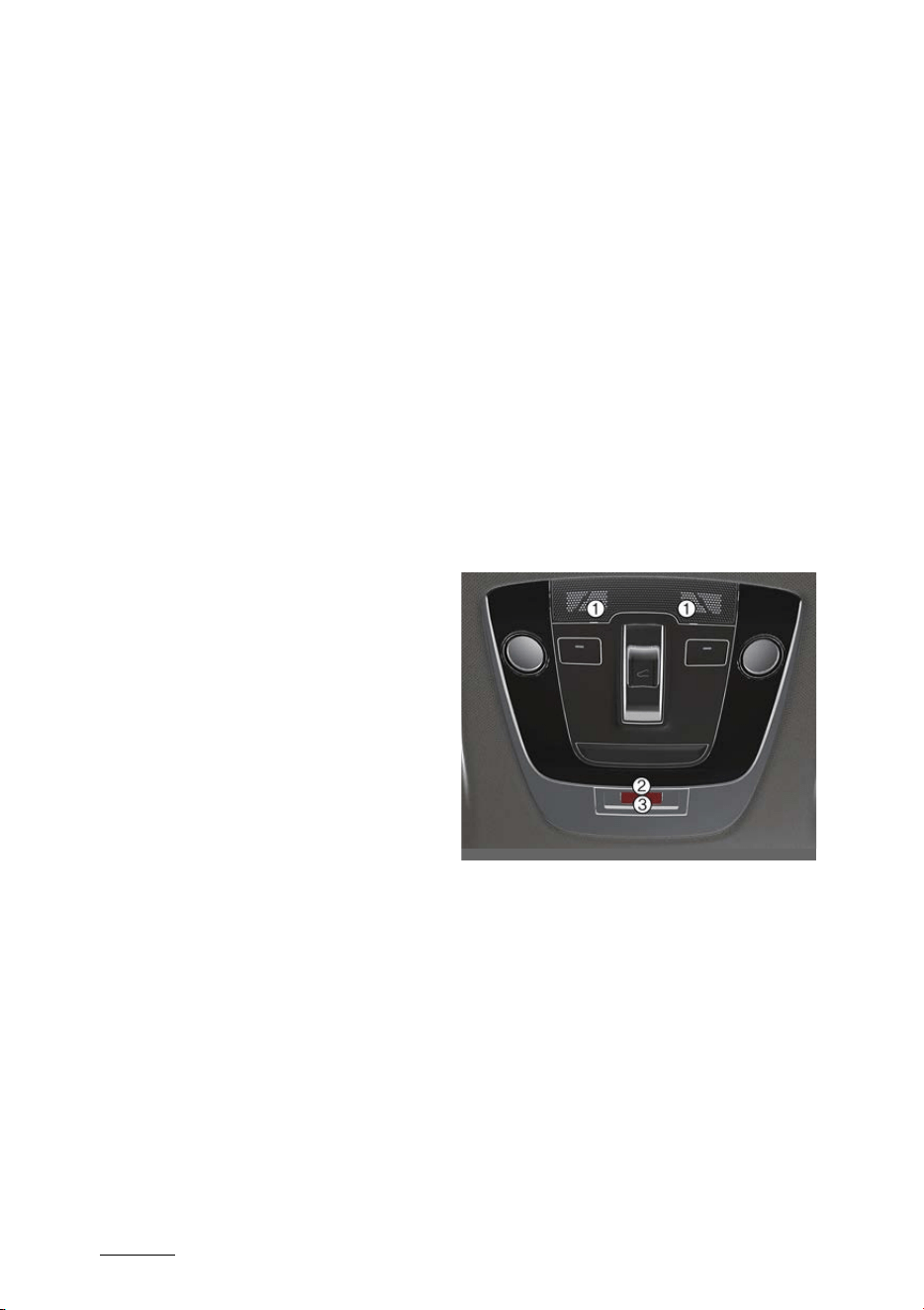
What to do in an emergency
207
Pan-European eCall system
Data Protection Regulation) (OJ L 119,
4.5.2016, p. 1). The Regulation applies
from 25 May 2018.
Arrangements for data process
-
ing
The 112-based eCall in-vehicle system is
designed in such a way as to ensure that
the data contained in the system mem
-
ory is not available outside the system
before an eCall is triggered. Additional
remarks (if any): Not applicable
The 112-based eCall in-vehicle system is
designed in such a way as to ensure that
it is not traceable and not subject to any
constant tracking in its normal operation
status. Additional remarks (if any): Not
applicable
The 112-based eCall in-vehicle system is
designed in such a way as to ensure that
data in the system internal memory is
automatically and continuously
removed.
The vehicle location data is constantly
overwritten in the internal memory of
the system so as always to keep maxi
-
mum of the last three up-to-date loca
-
tions of the vehicle necessary for the
normal functioning of the system.
The log of activity data in the 112- based
eCall in-vehicle system is kept for no
longer than necessary for attaining the
purpose of handling the emergency
eCall and in any case not beyond 13
hours from the moment an emergency
eCall was initiated. Additional remarks (if
any): Not applicable
Modalities for exercising data
subject's rights
The data subject (the vehicle's owner)
has a right of access to data and as
appropriate to request the rectification,
erasure or blocking of data, concerning
him or her, the processing of which does
not comply with the provisions of Direc
-
tive 95/46/EC. Any third parties to whom
the data have been disclosed have to be
notified of such rectification, erasure or
blocking carried out in compliance with
this Directive, unless it proves impossible
or involves a disproportionate effort.
The data subject has a right to complain
to the competent data protection
authority if he or she considers that his
or her rights have been infringed as a
result of the processing of his or her per
-
sonal data.
Contact service responsible for handling
access requests (if any): Not applicable
Pan-European eCall System
Elements of the Pan-European eCall sys
-
tem, installed in passenger compart
-
ment:
1
Microphone
2
SOS button
3
LED
SOS button: the driver/passenger makes
an emergency call to the single duty dis
-
patch service by pressing the button.
LED: The red and green LED illuminates
for 3 seconds when the ignition switch is
in the ON position. After that they will
OCV061021L
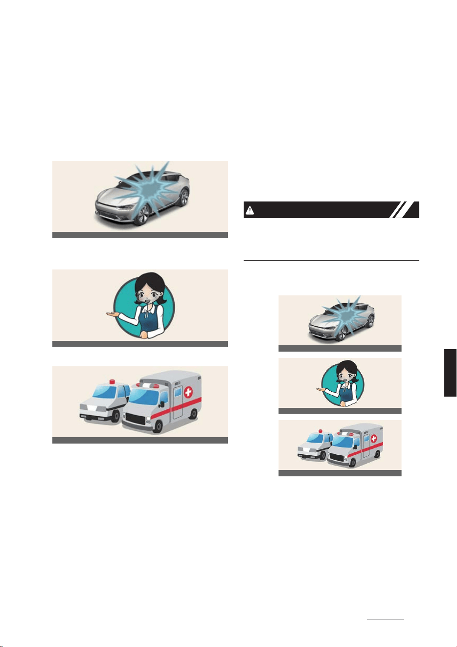
21
7
7
What to do in an emergency Pan-European eCall system
switch off at normal operation of the
system.
If there are some problems in the sys
-
tem, the LED remains in red.
Automatic accident reporting
1. System operation in the event of a
traffic accident
2. Connection with the Public Safety
Answering Point (PSAP)
3. Emergency services
The Pan-European eCall device auto
-
matically makes an emergency call to
the Public Safety Answering Point
(PSAP) for proper rescuing operations in
event of car accident.
For proper emergency services and sup
-
port the Pan-European eCall system
automatically transmits the accident
data to the Public Safety Answering
Point (PSAP) when a traffic accident is
detected.
In this case, the emergency call cannot
be hung up by pressing the SOS button
and the Pan-European eCall system
remains connected until the emergency
service officer, receiving the call, discon
-
nects the emergency call.
In minor traffic accidents the Pan- Euro
-
pean eCall system may not execute an
emergency call. However, an emergency
call may be made manually by pressing
the SOS button.
CAUTION
Operation of the system is impossible in
case of absence of mobile transmission
and GPS and Galileo signals.
Manual accident reporting
The driver or passenger manually can
make an emergency call in the Public
Safety Answering Point (PSAP), by
pressing SOS button to call the neces
-
sary emergency services.
A call to the emergency services through
the Pan-European eCall system can be
canceled by pressing the SOS button
again only before the call connection.
OCV061026L
OCV061027L
OCV061028L
1
2
3
OCV061026L
OCV061027L
OCV061028L

What to do in an emergency
227
Pan-European eCall system
After activation of emergency call in the
manual mode (for proper emergency
services and support), the Pan-European
eCall system automatically transmits the
road accident data / or data on other
accident to the officer of the Public
Safety Answering Point (PSAP) (during
emergency call) by pressing the SOS
button.
If the driver or passenger accidentally
presses the SOS button, it can be can
-
celed by pressing the button again in 3
seconds. It can’t be canceled after that.
In case of road accident or other acci
-
dent for activation of emergency call in
manual mode it is necessary:
1. Stop the car in accordance with traffic
rules to ensure safety to yourself and
other participants of road traffic;
2. Press the SOS button, when pressing
the button SOS registration of the
device in the wireless telephonic com
-
munication networks is carried out,
minimum data set about car and its
location is collected in accordance
with of the technical requirements of
the device.
After that connection with the officer
of the Pan-European eCall system is
made for clearing up reasons (condi
-
tions) of the emergency call.
3. After clearing up reasons of the emer
-
gency call, the officer of the Public
Safety Answering Point (PSAP) sends
emergency services and completes
the emergency call.
If the emergency call is not carried out in
accordance with the procedure, men
-
tioned above, the emergency call will be
considered as erroneous.
WARNING
Emergency power supply of the Pan-
European eCall system from the battery
僅 The Pan-European eCall system bat
-
tery supplies power during 1 hour in
case main power source of the vehicle
is cut off due to the collision during
the emergency situations.
僅 The Pan-European eCall system bat
-
tery should be replaced every 4 years.
LED illumination in red (system malfunc
-
tion)
If red LED illuminates in normal driving
conditions, this can indicate malfunction
of the Pan- European eCall system.
Please, have the Pan-European eCall
system checked at an authorized Kia
dealership immediately. Otherwise cor
-
rect operation of the Pan-European
eCall system device, installed in your car
is not guaranteed. Owner of the car
incurs liability for consequences,
occurred as a result of nonobservance of
conditions, mentioned above.
Arbitrary Removal or Modification
The Pan-European eCall system calls
emergency services for assistance. Thus,
any arbitrary removal or changes to the
Pan- European eCall system settings
may affect your driving safety. Also, it
may even make an erroneous emer
-
gency call to the Public Safety Answer
-
ing Point (PSAP). Thereby, we kindly ask
you not to make any changes by your
-
self or by the third parties in the settings
of the equipment of the Pan- European
eCall system, installed in your car.
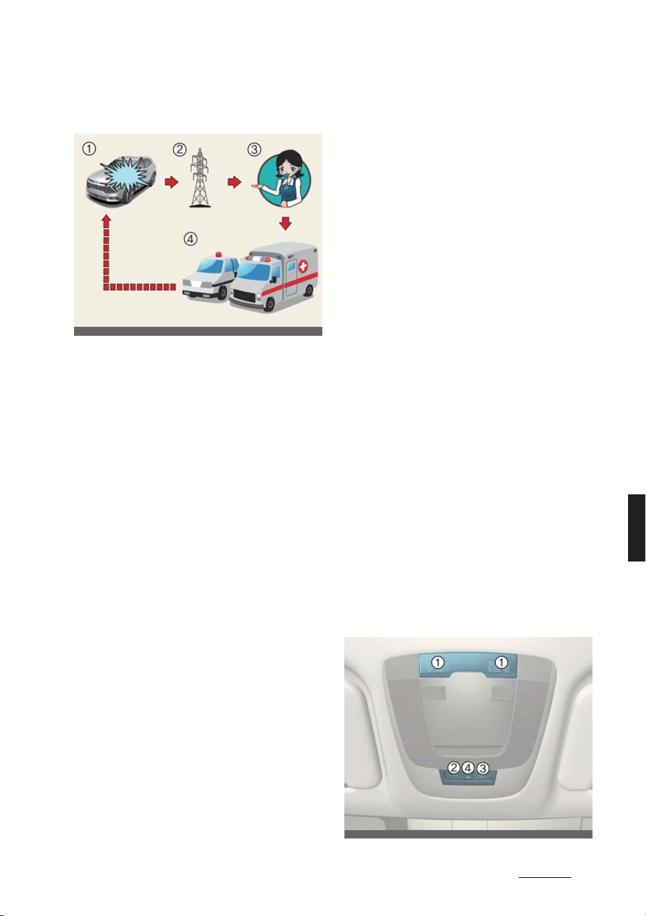
23
7
7
What to do in an emergency ERA-GLONASS emergency call
ERA-GLONASS emergency
call (if equipped)
1
Road accident
2
Wireless network
3
Single duty dispatch service (SDDS)
4
Rescue
The car is equipped with a device
*1
con
-
nected with the system ERA-GLONASS
for making emergency call to response
teams. The system ERA-GLONASS is an
automatic emergency call service made
in event of a traffic accident or other
*2
accidents on the roads of Russian Feder
-
ation. The system allows contacting with
an officer of the single duty dispatch
service in case of accidents on the roads
of Russian Federation.
The system ERA-GLONASS given condi
-
tions, stated in the Owner's Manual as
well as Warranty and Service book trans
-
mits data to the single duty dispatch ser
-
vice, including such information as
vehicle location, vehicle type, VIN (vehi
-
cle identification number of the car).
Once the data which stored in the ERA-
GLONASS system is delivered to the res
-
cue center to assist the driver and pas
-
sengers with proper rescue operations,
the data will be deleted after rescue
operation is completed.
Operator of the system ERA-GLONASS
(stock company "GLONASS") is responsi
-
ble for all components of the system
ERA-GLONASS (excluding equipment,
installed in the car) in accordance with
the federal law "On state automated
information system ERA-GLONASS" #
395-FZ from 28.12.2013.
1. * ERA-GLONASS device in the Owner's
Manual means equipment, installed
in the car, which provides connec
-
tion with the ERA-GLONASS system.
2. * "Other accidents" mean any acci
-
dents on the roads of Russian Fed
-
eration resulted in injured people
and/or necessity of provision of
assistance. In case of registration of
any accident, it is necessary to stop
a vehicle, press button SOS (location
of the button is specified on the pic
-
ture in the chapter "ERA-GLONASS
EMERGENCY CALL (IF EQUIPPED)")
of the Owner's Manual. When mak
-
ing a call, the system gathers infor
-
mation about the car (from which a
call was made), after which con
-
nects the car with an officer of the
single duty dispatch service to tell
about the reason of the emergency
call.
ERA-GLONASS system
ONQ5E051115L
ONQ5051016L
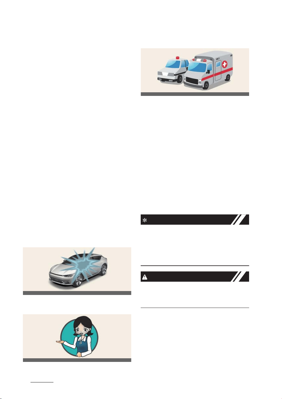
What to do in an emergency
247
ERA-GLONASS emergency call
1
Microphone
2
SOS button
3
SOS TEST button
4
LED
SOS button: the driver/passenger makes
an emergency call to the single duty dis
-
patch service by pressing the button.
SOS TEST button (test): the button is to
check working ability of the system in
the official dealership of Kia. The mode
"SOS TEST" can be activated strictly by
the specialist of the authorized dealer/
service partner of Kia. To avoid errone
-
ous calls, please, do not press this button
and do not activate the mode "SOS
TEST" by yourself.
LED: The red and green LED illuminates
for 3 seconds when the ignition switch is
in the ON position. After that they will
switch off at normal operation of the
system.
If there are some problems in the sys
-
tem, the LED remains in red.
Automatic accident reporting
1. System operation in the event of a
traffic accident
2. Connection with the single duty dis
-
patch service
3. Emergency services
The ERA-GLONASS device automatically
makes an emergency call to the single
duty dispatch service for proper rescu
-
ing operations in event of car accident.
For proper emergency services and sup
-
port the ERA-GLONASS system auto
-
matically transmits the accident data to
the single duty dispatch service when a
traffic accident is detected.
In this case, the emergency call cannot
be hung up by pressing the SOS button
and the ERA-GLONASS system remains
connected until the emergency service
officer, receiving the call, disconnects
the emergency call.
NOTICE
In even of minor traffic accidents the
ERA-GLONASS system may not execute
an emergency call. However, an emer
-
gency call may be made manually by
pressing the SOS button.
CAUTION
Operation of the system is impossible in
case of absence of mobile transmission
and GPS and GLONASS signals.
Manual accident reporting
1. Pressing the SOS button
OCV061026L
OCV061027L
OCV061028L
25
7
7
What to do in an emergency ERA-GLONASS emergency call
2. Connection with the single duty dis
-
patch service
3. Emergency services
Driver or passenger manually can make
an emergency call in the single duty dis
-
patch service, by pressing SOS button to
call the necessary emergency services.
A call to the emergency services through
the ERA-GLONASS system can be can
-
celed by pressing the SOS button again
only before the call connection.
After activation of emergency call in the
manual mode (for proper emergency
services and support), the ERA-GLON
-
ASS system automatically transmits the
road accident data/or data on other
accident to the officer of the single duty
dispatch service (during emergency call)
by pressing the SOS button.
In case of road accident or other acci
-
dent for activation of emergency call in
manual mode it is necessary:
1. Stop a car, after which in accordance
with traffic rules to ensure safety to
yourself and other participants of
road traffic;
2. Press the SOS button, when pressing
the button SOS registration of the
device in the wireless telephonic com
-
munication networks is carried out,
minimum data set about car and its
location is collected in accordance
with of the technical requirements of
the device. After that connection with
the officer of the ERA-GLONASS sys
-
tem is made for clearing up reasons
(conditions) of the emergency call.
3. After clearing up reasons of the emer
-
gency call, the officer of the single
duty dispatch service sends minimum
data set to emergency services and
completes the emergency call.
If the emergency call is not carried out in
accordance with the procedure, men
-
tioned above, the emergency call will be
considered as erroneous.
WARNING
Emergency power supply of the system
ERA-GLONASS from the battery
僅 The ERA-GLONASS system battery
supplies power during 1 hour in case
main power source of the vehicle is
cut off due to the collision during the
emergency situations.
僅 The ERA-GLONASS system battery
should be replaced every 4 years.
LED illumination in red (system malfunc
-
tion)
If red LED illuminates in normal driving
conditions, this can indicate malfunction
of the ERA-GLONASS system. Please,
have the ERA-GLONASS system
checked at an authorized Kia dealer/ser
-
vice partner immediately. Otherwise cor
-
ONQ5051015L
OCV061027L
OCV061028L
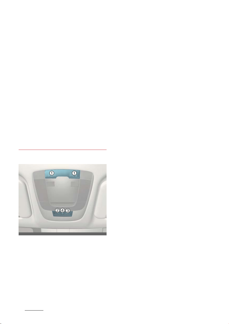
What to do in an emergency
267
ERA-GLONASS emergency call
rect operation of the ERA-GLONASS
system device, installed in your car is not
guaranteed. Owner of the car incurs lia
-
bility for consequences, occurred as a
result of nonobservance of conditions,
mentioned above.
Arbitrary Removal or Modification
The ERA-GLONASS system calls emer
-
gency services for assistance. Thus, any
arbitrary removal or changes to the
ERA-GLONASS system settings may
affect your driving safety. Also, it may
even make an erroneous emergency call
to the single duty dispatch service.
Thereby, we kindly ask you not to make
any changes by yourself or by the third
parties in the settings of the equipment
of the ERA-GLONASS system, installed
in your car.
Test Mode
Elements of the system ERA-GLONASS,
installed in passenger compartment:
1
Microphone
2
SOS button
3
SOS TEST button
4
LED
There is a technical opportunity to check
working ability of the ERA-GLONASS
device, installed in your car. In order to
avoid making erroneous calls and incor
-
rect operation of the device, checking of
the ERA-GLONASS device, installed in
your car, should be carried out only by
specialists of authorized Kia dealer/ser
-
vice partner and on their territory in
accordance with the following manual
(on applying user interface for launching
test mode).
You can start the ERA-GLONASS test
mode by pressing the SOS TEST button.
The test mode starts with a voice guid
-
ance to check working ability of the
ERA-GLONASS device. In the course of
checking working ability of the ERA-
GLONASS device red and green LED illu
-
minate.
Re-press the SOS TEST button again to
deactivate the test mode during the
voice guidance.
ONQ5051016L

8Maintenance
Maintenance
Motor room compartment............................................................8-3
Maintenance services....................................................................8-4
僅 Owner's responsibility....................................................................................8-4
僅 Owner maintenance precautions .............................................................8-4
Owner maintenance schedule .....................................................8-5
僅 When you stop for charging ....................................................................... 8-5
Scheduled maintenance service ..................................................8-6
Coolant............................................................................................8-9
Brake fluid ......................................................................................8-9
僅 Checking the brake fluid level....................................................................8-9
Washer fluid .................................................................................8-10
僅 Checking the washer fluid level...............................................................8-10
Climate control air filter ..............................................................8-11
僅 Replacing the climate control air filter...................................................8-11
Wiper blade .................................................................................. 8-12
僅 Replacing the front wiper blade.............................................................. 8-12
Battery .......................................................................................... 8-13
僅 For best battery service .............................................................................. 8-13
僅 Battery capacity label...................................................................................8-14
僅 Battery recharging.........................................................................................8-14
僅 Reset items ....................................................................................................... 8-15
Tires and wheels.......................................................................... 8-15
僅 Tire care ............................................................................................................. 8-15
僅 Recommended cold tire inflation pressures......................................8-15
僅 Checking tire inflation pressure............................................................... 8-15
僅 Tire rotation ...................................................................................................... 8-17
僅 Wheel alignment and tire balance.......................................................... 8-17
僅 Tire replacement ............................................................................................ 8-17
僅 Wheel replacement .......................................................................................8-18

8 Maintenance
僅 Tire traction ...................................................................................................... 8-18
僅 Tire maintenance ........................................................................................... 8-18
僅 Tire sidewall labeling.................................................................................... 8-19
僅 Low aspect ratio tire ......................................................................................8-21
Fuses............................................................................................. 8-22
僅 Replacing inner panel fuse........................................................................8-23
僅 Replacing motor room fuse.......................................................................8-24
僅 Fuse/relay panel description ....................................................................8-25
Lamps ........................................................................................... 8-33
僅 Bulb replacement precautions.................................................................8-33
僅 Light position (Front)....................................................................................8-34
僅 Light position (Rear) .....................................................................................8-35
僅 Light position (Side) ......................................................................................8-35
僅 Replacing lights ..............................................................................................8-35
僅 Headlamp aiming (for Europe)................................................................8-35
Appearance care.........................................................................8-40
僅 Exterior care....................................................................................................8-40
僅 Interior care ..................................................................................................... 8-44
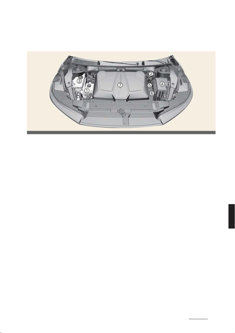
3
8
8
Maintenance Motor room compartment
Maintenance
Motor room compartment
* The actual features in your vehicle may not necessarily be available due to the
selected options or regions.
1
Coolant reservoir
2
Brake fluid reservoir
* This part is located on the opposite side for Right-hand drive vehicle.
3
Windshield washer fluid reservoir
4
Fuse box
5
Negative battery terminal (-)
6
Positive battery terminal (+)
7
Front trunk
OCV071001L

Maintenance
48
Maintenance services
Maintenance services
Owner's responsibility
僅 Have your vehicle serviced by a pro
-
fessional workshop. Kia recommends
visiting an authorized Kia dealer/ser
-
vice partner.
僅 Retain documents that show proper
maintenance.
僅 Establish your compliance with the
servicing and maintenance require
-
ments of your vehicle warranties.
僅 Repairs and adjustments required as
a result of improper maintenance or
lack of required maintenance are not
covered even when your vehicle's
warranty has not yet expired.
NOTICE
Maintenance Service and Record Reten
-
tion are the owner's responsibility.
Owner maintenance precautions
Improper or incomplete service may
result in problems. This section gives
instructions only for the maintenance
items that are easy to perform.
WARNING
僅 Performing maintenance work on a
vehicle can be dangerous. You can be
seriously injured while performing
some maintenance procedures. If you
lack sufficient knowledge and experi
-
ence or the proper tools and equip
-
ment to do the work, have the system
serviced by a professional workshop.
Kia recommends visiting an autho
-
rized Kia dealer/service partner.
僅 Working under the hood with the
vehicle running is dangerous. It
becomes even more dangerous when
you wear jewelry or loose clothing.
These can become entangled in mov
-
ing parts and result in injury. There
-
fore, if you must run the vehicle while
working under the hood, make certain
that you remove all jewelry (especially
rings, bracelets, watches, and neck
-
laces) and all neckties, scarves, and
similar loose clothing before getting
near the vehicle or cooling fans.
CAUTION
僅 Before touching the battery and elec
-
trical wiring, you should disconnect
the battery (-) terminal. You may get
an electric shock from the electric cur
-
rent.
僅 When you remove the interior trim
cover with a flat-blade screwdriver, be
careful not to damage the cover.
僅 Be careful when you replace and
clean bulbs to avoid burns or electri
-
cal shock.
NOTICE
Improper owner maintenance during the
warranty period may affect warranty
coverage. For details, read the separate
Warranty & Maintenance book provided
with the vehicle. If you're unsure about
any servicing or maintenance proce
-
dure, have the system serviced by a pro
-
fessional workshop. Kia recommends
visiting an authorized Kia dealer/service
partner.

5
8
8
Maintenance Owner maintenance schedule
Owner maintenance schedule
When you stop for charging
僅 Check the coolant level in the coolant
reservoir.
僅 Check the windshield washer fluid
level.
僅 Look for low or underinflated tires.
WARNING
Be careful when checking your coolant
level when the motor compartment is
hot. Scalding hot coolant and steam may
blow out under pressure. This could
cause burns or other serious injury.
While operating your vehicle
僅 Check for vibrations in the steering
wheel. Notice any increased steering
effort or looseness in the steering
wheel, or change in its straight ahead
position.
僅 Notice if your vehicle constantly turns
slightly or "pulls" to one side when
traveling on smooth, level road.
僅 When stopping, listen and check for
unusual sounds, pulling to one side,
increased brake pedal travel, and
"hard-to-push" brake pedal.
僅 If any slipping or changes in the oper
-
ation of your gear shift occurs, check
the gear fluid level.
僅 Check the parking brake.
僅 Check for fluid leaks under your vehi
-
cle (water dripping from the air condi
-
tioning system during or after use is
normal).
At least monthly
僅 Check the coolant level in the coolant
reservoir.
僅 Check the operation of all exterior
lights, including the stoplights, turn
signals and hazard warning flashers.
僅 Check the inflation pressures of all
tires including the spare and look for
tires that are worn of which show
uneven wear or damage.
僅 Check for loose wheel lug nuts.
At least twice a year
僅 Check the cooling system, heater, and
air conditioning hoses for leaks or
damage.
僅 Check the windshield washer spray
and wiper operation. Clean the wiper
blades with clean cloth dampened
with washer fluid.
僅 Check the headlamp alignment.
僅 Check the lap/shoulder belts for wear
and proper functioning.
At least once a year
僅 Clean the body and door drain holes.
僅 Lubricate the door hinges and hood
hinges.
僅 Lubricate the locks and latches of the
doors and hood.
僅 Lubricate the door rubber weather
-
strips.
僅 Check the air conditioning system.
僅 Inspect and lubricate the shift gear
linkage and controls.
僅 Clean the battery and terminals.
僅 Check the brake fluid level.

Maintenance
68
Scheduled maintenance service
Scheduled maintenance service
Normal maintenance schedule - for Europe (Except Russia)
I: Inspect and adjust, correct, clean, or replace if necessary.
R: Replace or change.
* 1: When replacing or adding coolant, we recommend that you visit an authorized Kia
dealer/service partner.
* 2: For your convenience, it can be replaced prior to its interval when you are doing
other maintenance tasks.
* 3: We recommend that the coolant level and leak is checked on a daily basis.
* 4:
Brake discs and pads
Check the pads for excessive wear, discs for run out and wear, and calipers for fluid
leakage.
For more information on checking the pads or lining wear limit, we recommend to
refer to the Kia web site.
(www.kia-hotline.com)
Number of months or driving distance, whichever comes first
Months 24 48 72 96 120 144 168 192
Miles×1,000 20 40 60 80 100 120 140 160
Km×1,000 30 60 90 120 150 180 210 240
Coolant
*1*2
At first, Replace 210,000 km (140,000 miles) or 120 months
After that, Replace every 30,000 km (20,000 miles) or 24 months
Reduction gear fluid - I - I - I - I
Drive shafts and boots I I I I I I I I
Cooling system
*3
- I I I I I I I
Air conditioner refrigerant/compressor (if
equipped)
I I I I I I I I
Climate control air filter R R R R R R R R
Brake discs and pads
*4
I I I I I I I I
Brake lines, hoses and connections I I I I I I I I
Brake fluid R R R R R R R R
Steering gear rack, linkage and boots I I I I I I I I
Suspension ball joints I I I I I I I I
Tire (pressure & tread wear) I I I I I I I I
12V Battery condition I I I I I I I I
Pan-European eCall system battery (if
equipped)
Replace every 4 years

7
8
8
Maintenance Scheduled maintenance service
Normal maintenance schedule - except Europe (Including Russia)
I: Inspect and adjust, correct, clean, or replace if necessary.
R: Replace or change.
* 1: When replacing or adding coolant, we recommend that you visit an authorized Kia
dealer/service partner.
* 2: For your convenience, it can be replaced prior to its interval when you are doing
other maintenance tasks.
* 3: We recommend that the coolant level and leak is checked on a daily basis.
* 4:
Brake discs and pads
Check the pads for excessive wear, discs for run out and wear, and calipers for fluid
leakage.
For more information on checking the pads or lining wear limit, we recommend to
refer to the Kia web site.
(www.kia-hotline.com)
Number of months or driving distance, whichever comes first
Months 12 24 36 48 60 72 84 96
Miles×1,000 10 20 30 40 50 60 70 80
Km×1,000 15 30 45 60 75 90 105 120
Coolant
*1*2
At first, Replace 210,000 km (140,000 miles) or 120 months
After that, Replace every 30,000 km (20,000 miles) or 24 months
Reduction gear fluid - - - I - - - I
Drive shafts and boots - I - I - I - I
Cooling system
*3
- - - I - I - I
Air conditioner refrigerant/compressor (if equipped) I I I I I I I I
Climate control air filter
For Australia, New Zea
-
land
I R I R I R I R
Except Australia, New
Zealand
R R R R R R R R
Brake discs and pads
*4
- I - I - I - I
Brake lines, hoses and connections - I - I - I - I
Brake fluid
For Australia, New Zea
-
land
I R I R I R I R
Except Australia, New
Zealand
I I R I I R I I
Steering gear rack, linkage and boots I I I I I I I I
Suspension ball joints I I I I I I I I
Tire (pressure & tread wear) I I I I I I I I
12V Battery condition I I I I I I I I
ERA-GLONASS system (if equipped) I I I I I I I I
ERA-GLONASS system battery (if equipped) Replace every 4 years

Maintenance
88
Scheduled maintenance service
Maintenance under severe usage conditions
I: Inspect and adjust, correct, clean, or replace if necessary.
R: Replace or change.
Severe driving conditions
A. Repeatedly driving short distance of less than 8 km (5 miles) in normal tempera
-
ture or less than 16 km (10 miles) in freezing temperature
B. Driving on rough, dusty, muddy, unpaved, graveled or salt spread roads
C. Driving in areas using salt or other corrosive materials or in very cold weather
D. Driving in heavy dust condition
E. Driving in heavy traffic area with the ambient temperature higher than 32 ºC (90
ºF) while consuming more than 50% of electric energy.
F. Driving on uphill, downhill, or mountain roads repeatedly
G. Towing a trailer, or using a camper or roof rack
H. Driving as a patrol car, taxi, other commercial use or vehicle towing
I. Frequently driving under high speed or rapid acceleration/deceleration
J. Frequently driving in stop-and-go conditions
Maintenance Item Maintenance Operation Maintenance Intervals Driving Condition
Reduction gear fluid R Every 120,000 km (80,000 miles) A, B, E, F, H, J
Drive shaft and boots I
Inspect more frequently depending on the
condition
B, C, D, E, F, G, H, I
Climate control air filter R
Replace more frequently depending on the
condition
B, D, F
Brake discs, pads and cal
-
ipers
I
Inspect more frequently depending on the
condition
B, C, D, F, G, H, I, J
Steering-gear rack, link
-
age, and boots
I
Inspect more frequently depending on the
condition
C, D, E, F, G
Suspension ball joints I
Inspect more frequently depending on the
condition
B, C, D, E, F
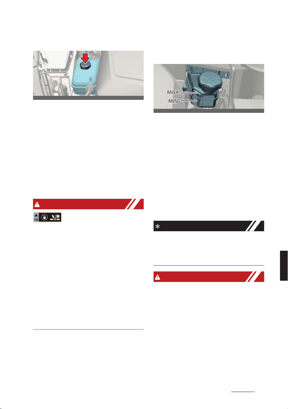
9
8
8
Maintenance Coolant
Coolant
Check the condition and connections of
all the cooling system hoses and heater
hoses. Replace any swollen or deterio
-
rated hoses.
The coolant level should be filled
between the MAX or F and the MIN or L
marks on the side of the coolant reser
-
voir when the parts in the motor com
-
partment is cool.
If the coolant is low, we recommend to
visit an authorized Kia dealer/service
partner.
WARNING
The electric motor for the
cooling fan may continue to
operate or start up when the
vehicle is not running and can cause
serious injury.
Keep hands, clothing and tools away
from the rotating fan blades of the cool
-
ing fan.
The electric motor for the cooling fan is
controlled by vehicle coolant tempera
-
ture, refrigerant pressure and vehicle
speed. As the vehicle coolant tempera
-
ture decreases, the electric motor will
automatically shut off. This is a normal
condition.
Brake fluid
Checking the brake fluid level
Operation
僅 Clean the area around the reservoir
cap.
僅 Periodically check that the fluid level
in the brake fluid reservoir is between
MIN and MAX. The level will fall as the
vehicle's mileage increases. This is a
normal condition associated with the
wear of the brake linings.
Use only the specified brake fluid. (Refer
to "Recommended lubricants and capac
-
ities" on page 9-7.)
INFORMATION
If the fluid level is excessively low, have
the system checked by a professional
workshop. Kia recommends visiting an
authorized Kia dealer/service partner.
WARNING
僅 In the event the brake system requires
frequent additions of fluid, have the
system inspected by a professional
workshop. Kia recommends visiting
an authorized Kia dealer/service part
-
ner.
OCV071002L
OCV071003L
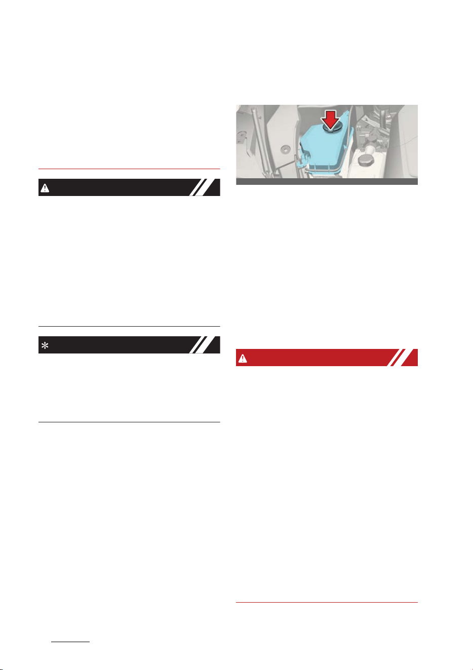
Maintenance
108
Washer fluid
僅 When changing and adding brake
fluid, handle it carefully. Do not let it
come in contact with your eyes. If
brake fluid should come in contact
with your eyes, immediately flush
them with a large quantity of fresh tap
water. Have your eyes examined by a
doctor as soon as possible.
CAUTION
Do not allow brake fluid to contact the
vehicle's body paint, as paint damage
will result. Brake fluid, which has been
exposed to open air for an extended
time should never be used as its quality
cannot be guaranteed. It should be
properly disposed. Don't put in the
wrong kind of fluid. A few drops of min
-
eral-based oil in your brake system can
damage brake system parts.
NOTICE
To maintain your vehicle`s best brake
and ABS/ESC performance, use Kia gen
-
uine brake fluid or those of an equiva
-
lent standard brake fluid as in the
specification.
Washer fluid
Checking the washer fluid level
Operation
僅 Check the fluid level in the washer
fluid reservoir and add fluid if neces
-
sary. Plain water may be used if
washer fluid is not available.
僅 However, use washer solvent with
antifreeze characteristics in cold cli
-
mates to prevent freezing.
The reservoir is translucent so that you
can check the level with a quick visual
inspection.
WARNING
僅 Do not use coolant or antifreeze in the
washer fluid reservoir.
僅 Coolant can severely obscure visibility
when sprayed on the windshield and
may cause loss of vehicle control or
damage to paint and body trim.
僅 Windshield Washer fluid agents con
-
tain some amounts of alcohol and can
be flammable under certain circum
-
stances. Do not allow sparks or flame
to contact the washer fluid or the
washer fluid reservoir. Damage to the
vehicle or occupants could occur.
僅 Windshield washer fluid is poisonous
to humans and animals. Do not drink
and avoid contacting windshield
washer fluid. Serious injury or death
could occur.
OCV071004L
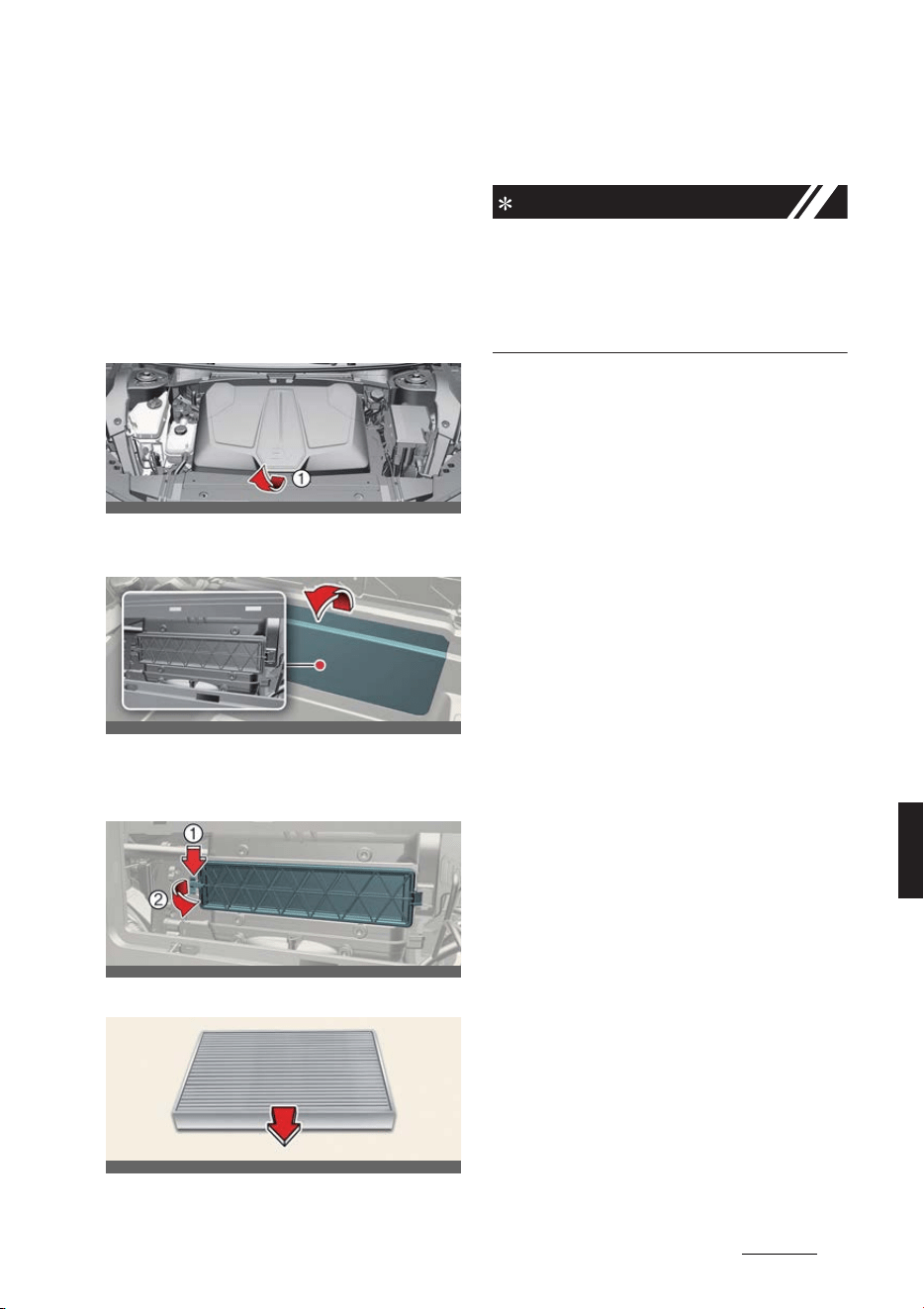
11
8
8
Maintenance Climate control air filter
Climate control air filter
Replacing the climate control air
filter
Operation
1. Open the hood and lift up the front
trunk cover while depressing the front
trunk lever (1).
2. Remove the cover by pulling the
upper part of the cover.
3. Remove the climate control air filter
cover (2) by pulling out both sides of
the cover (1).
4. Replace the climate control air filter.
5. Reassemble in reverse order of disas
-
sembly.
NOTICE
When replacing the climate control air
filter install it properly. Otherwise, the
system may produce noise and the
effectiveness of the filter may be
reduced.
OCV041014L
OCV071005K
OCV071006K
OCV071048L
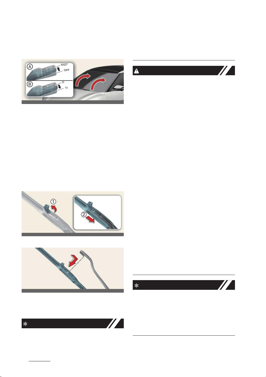
Maintenance
128
Wiper blade
Wiper blade
Replacing the front wiper blade
Operation
1. Turn off the vehicle.
2. Move the wiper switch to the single
wiping (MIST/1x) position within 20
seconds.
3. Hold the wiper switch for more than 2
seconds.
4. Raise the wiper arm.
5. Lift the wiper blade clip up. Pull down
the blade assembly and remove it.
6. Install the new blade assembly.
7. Upon starting the vehicle, the wiper
arms will return to their normal oper
-
ating position.
INFORMATION
To prevent damage to the wiper arms or
other components, have the wiper blade
replaced by a professional workshop.
Kia recommends visiting an authorized
Kia dealer/service partner.
CAUTION
僅 Do not use gasoline, kerosene, paint
thinner, or other solvents on or near
them.
僅 Do not attempt to move the wipers
manually.
僅 The use of a non-specified wiper
blade could result in wiper malfunc
-
tion and failure.
僅 Do not allow the wiper arm to fall
against the windshield, since it may
chip or crack the windshield.
僅 If the wiper arm receives too much
force while pulling the blade, the cen
-
ter part may be damaged.
僅 The wiper could not operate for
approximately 10 seconds when the
wiper is operated without washer fluid
or the blades are frozen. This is not a
malfunction, it is a wiper protection
system activated by motor overload
circuit within the wiper motor.
僅 The front windshield should be
cleaned with water hose and wiped
with clean towel with wiper blades
raised up. Also, the wiper blades
should be wiped clean when the
grease or wax is applied to the blades.
NOTICE
Commercial hot waxes applied by auto
-
matic car washes have been known to
make the windshield difficult to clean.
And it is the responsibility of customers
to wash and manage the vehicle with
adequate methods and materials.
OCV071069L_2
OCV071011L
OCV071012L
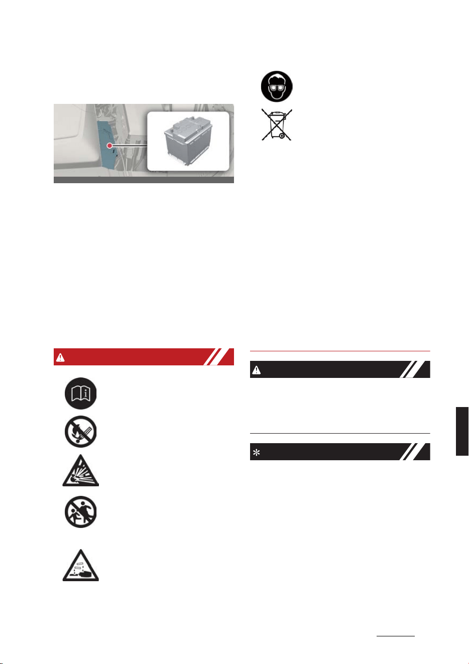
13
8
8
Maintenance Battery
Battery
For best battery service
僅 Keep the battery securely mounted.
僅 Keep the top of the battery clean and
dry.
僅 Keep the terminals and connections
clean, tight, and coated with petro
-
leum jelly or terminal grease.
僅 Immediately rinse any electrolyte
spilled from the battery using a solu
-
tion of water and baking soda.
僅 If the vehicle is not going to be used
for an extended period, disconnect
the battery cables.
WARNING
僅 When lifting a plastic-cased battery,
excessive pressure on the case may
cause battery acid to leak, resulting in
personal injury. Lift with a battery car
-
rier or with your hands on opposite
corners.
僅 Never attempt to recharge the battery
when the battery cables are con
-
nected.
僅 The electrical ignition system works
with high voltage. Never touch these
components with the
READY
indica
-
tor ON or when the EV button is in the
ON position.
Failure to follow the above warnings can
result in serious bodily injury or death.
CAUTION
If you connect unauthorized electronic
devices to the battery, the battery may
be discharged. Never use unauthorized
devices.
NOTICE
Your vehicle is equipped with mainte
-
nance free battery. If your vehicle is
equipped with the battery marked with
LOWER and UPPER on the side, you can
check the electrolyte level. The electro
-
lyte level should be between LOWER
and UPPER. If the electrolyte level is low,
it needs to add distilled (demineralized)
water (Never add sulfuric acid or other
electrolyte). When refill, be careful not to
splash the battery and adjacent compo
-
nents. And do not overfill the battery
Always read the following instructions
carefully when handling a battery.
Keep lighted cigarettes and all other flames
or sparks away from the battery.
Hydrogen, a highly combustible gas, is
always present in battery cells and may
explode if ignited.
Keep batteries out of the reach of children
because batteries contain highly corrosive
SULFURIC ACID. Do not allow battery acid
to contact your skin, eyes, clothing or paint
finish.
If any electrolyte gets into your eyes, flush
your eyes with clean water for at least 15
minutes and get immediate medical atten
-
tion. If electrolyte gets on your skin, thor
-
oughly wash the contacted area. If you feel
pain or burning sensation, get medical
attention immediately.
OCV071008L
Wear eye protection when charging or
working near a battery. Always provide
ventilation when working in an enclosed
space.
An inappropriately disposed battery can
be harmful to the environment and human
health. Dispose the battery according to
your local law(s) or regulation.
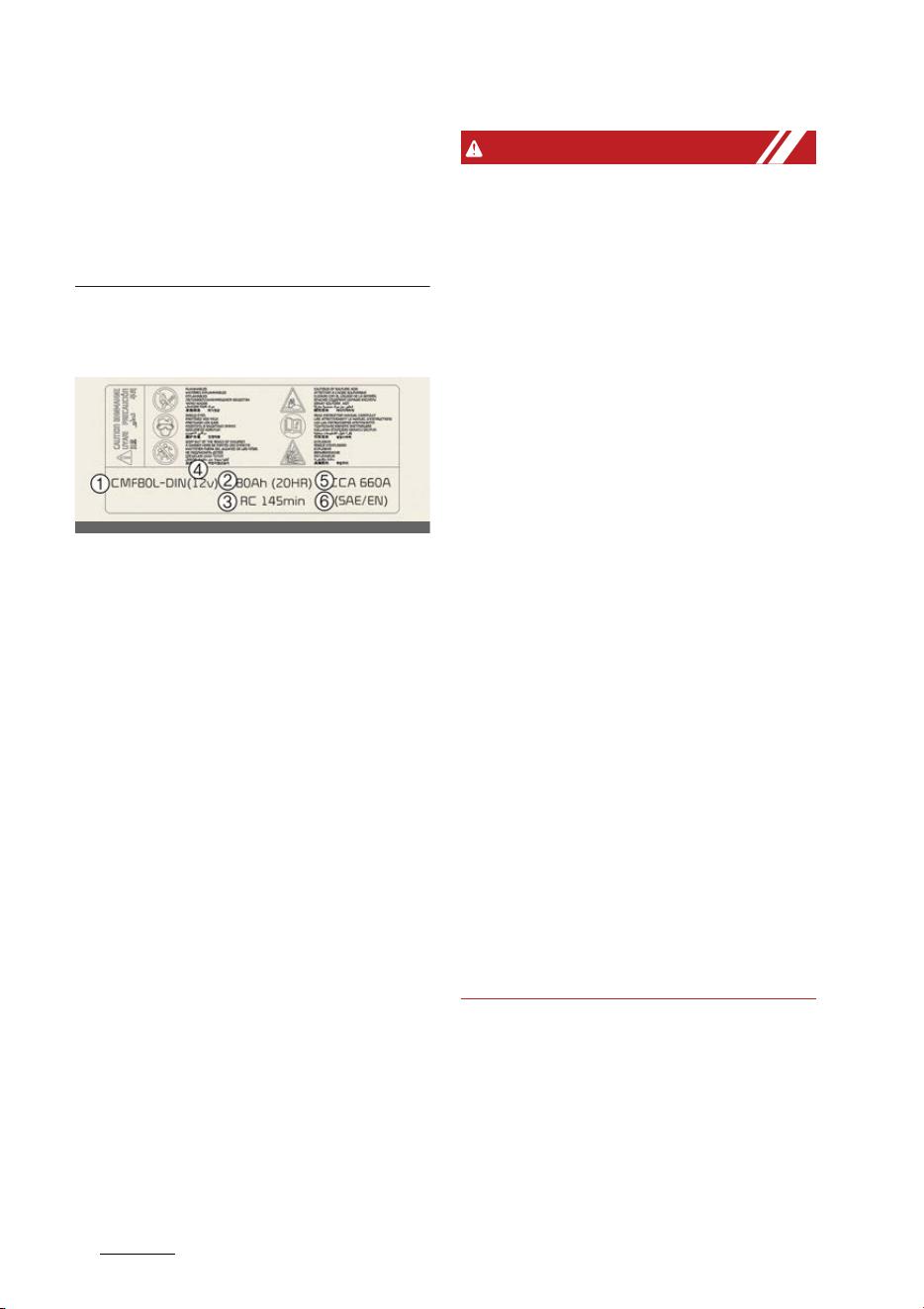
Maintenance
148
Battery
cells. It can cause corrosion on other
parts. Make sure that the cell caps are
tightened.
Contact a professional workshop. Kia
recommends visiting an authorized Kia
dealer/service partner.
Battery capacity label
Example
* The actual battery label in the vehicle
may differ from the illustration.
1
The Kia model name of battery
2
The nominal capacity (in Ampere
hours)
3
The nominal reserve capacity (in min.)
4
The nominal voltage
5
The cold-test current in amperes by
SAE
6
The cold-test current in amperes by
EN
Battery recharging
Your vehicle has a maintenance-free,
calcium-based battery.
僅 If the battery becomes discharged in a
short time recharge it by slow
charging (trickle) for 10 hours.
僅 If the battery gradually discharges
because of high electric load while the
vehicle is being used, recharge it at
20~30 A for 2 hours.
WARNING
僅 When recharging the battery, observe
the following precautions:
- The battery must be removed from
the vehicle and placed in an area
with good ventilation.
- Do not allow cigarettes, sparks, or
flame near the battery.
- Watch the battery during charging,
and stop or reduce the charging
rate if the battery cells begin gas
-
sing (boiling) violently or if the tem
-
perature of the electrolyte of any
cell exceeds 49°C (120°F).
- Wear eye protection when checking
the battery during charging.
- Disconnect the battery charger in
the following order.
1. Turn off the battery charger main
switch.
2. Unhook the negative clamp from
the negative battery terminal.
3. Unhook the positive clamp from the
positive battery terminal.
僅 Before performing maintenance or
recharging the battery, turn off all
accessories and stop the vehicle.
僅 The negative battery cable must be
removed first and installed last when
the battery is disconnected.
僅 We recommend that you use batteries
for replacement from an authorized
Kia dealer/service partner.
OCV071057L
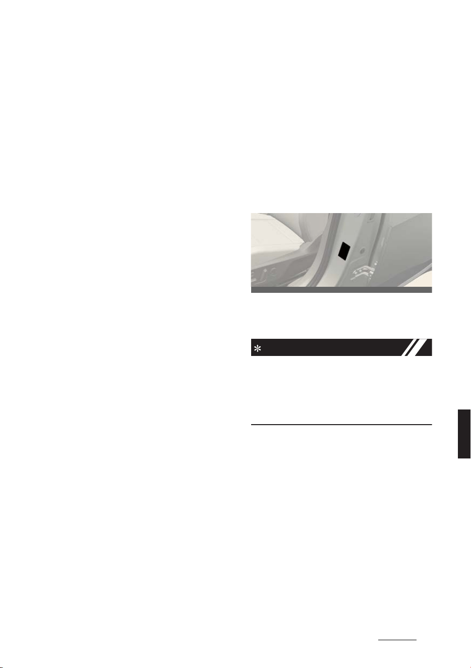
15
8
8
Maintenance Tires and wheels
Reset items
Items should be reset after the battery
has been discharged or the battery has
been disconnected.
僅 Auto up/down window
僅Wide sunroof
僅 Trip computer
僅 Climate control system
僅 Integrated Memory System
僅Audio
Tires and wheels
Tire care
For proper maintenance, safety, and
maximum electric energy economy, you
must always maintain recommended tire
inflation pressures and stay within the
load limits and weight distribution rec
-
ommended for your vehicle.
Recommended cold tire inflation
pressures
All specifications (sizes and pressures)
can be found on a label attached to the
vehicle.
INFORMATION
All tire pressures (including the spare)
should be checked when the tires are
cold. "Cold Tires" means the vehicle has
not been driven for at least three hours
or driven less than 1.6 km (1 mile).
Checking tire inflation pressure
僅 Remove the valve cap from the tire
valve stem. Press the tire gauge firmly
onto the valve to get a pressure mea
-
surement. If the pressure is low, add
air until you reach the recommended
amount.
僅 If you overfill the tire, release air by
pushing on the metal stem in the cen
-
ter of the tire valve. Be sure to put the
valve caps back on the valve stems.
OCV071009L

Maintenance
168
Tires and wheels
WARNING
僅 Overinflation or underinflation can
reduce tire life, adversely affect vehi
-
cle handling, and lead to sudden tire
failure. This could result in loss of
vehicle control and potential injury.
僅 Severe underinflation (70 kPa (10 psi)
or more) can lead to severe heat
build-up, causing blowouts, tread sep
-
aration and other tire failures that can
result in the loss of vehicle control
leading to severe injury or death. This
risk is much higher on hot days and
when driving for long periods at high
speeds.
僅 Inspect your tires frequently for
proper inflation as well as wear and
damage. Always use a tire pressure
gauge.
僅 Tires with too much or too little pres
-
sure wear unevenly causing poor han
-
dling, loss of vehicle control, and
sudden tire failure leading to acci
-
dents, injuries, and even death. The
recommended cold tire pressure for
your vehicle can be found in this man
-
ual and on the tire label located on the
driver's side center pillar.
僅 Worn tires can cause accidents.
Replace tires that are worn, show
uneven wear, or are damaged.
僅 Remember to check the pressure of
your spare tire. Kia recommends that
you check the spare every time you
check the pressure of the other tires
on your vehicle.
CAUTION
僅 Underinflation also results in exces
-
sive wear, poor handling and reduced
electric energy economy. Wheel
deformation also is possible. Keep
your tire pressures at the proper lev
-
els. If a tire frequently needs refilling,
have the system checked by a profes
-
sional workshop. Kia recommends to
visit an authorized Kia dealer/service
partner.
僅 Overinflation produces a harsh ride,
excessive wear at the center of the
tire tread, and a greater possibility of
damage from road hazards.
僅 Warm tires normally exceed recom
-
mended cold tire pressures by 28 to
41 kPa (4 to 6 psi). Do not release air
from warm tires to adjust the pressure
or the tires will be underinflated.
僅 Be sure to reinstall the tire inflation
valve caps. Without the valve cap, dirt
or moisture could get into the valve
core and cause air leakage. If a valve
cap is missing, install a new one as
soon as possible.
僅 Always observe the following:
- Check tire pressure when the tires
are cold. (After vehicle has been
parked for at least three hours or
hasn't been driven more than 1.6
km (one mile) since startup.)
- Check the pressure of your spare
tire each time you check the pres
-
sure of other tires.
- Never overload your vehicle. Be
careful not to overload a vehicle
luggage rack if your vehicle is
equipped with one.
- Worn, old tires can cause accidents.
If your tread is badly worn, or if
your tires have been damaged,
replace them.
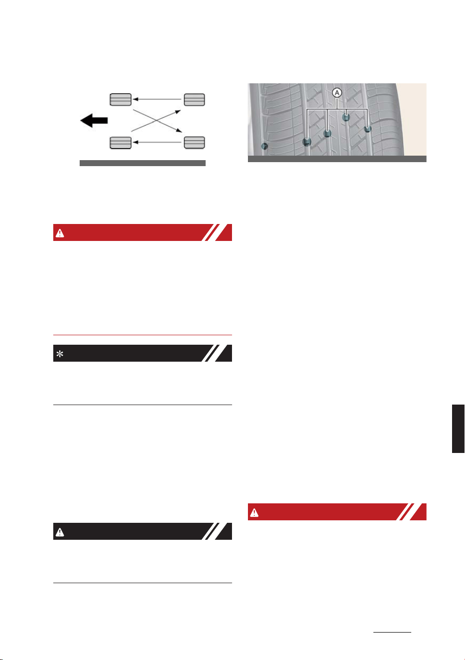
17
8
8
Maintenance Tires and wheels
Tire rotation
To equalize tread wear, it is recom
-
mended that the tires be rotated every
10,000 km (6,500 miles) or sooner if
irregular wear develops.
WARNING
僅 Do not use the compact spare tire for
tire rotation.
僅 Do not mix bias ply and radial ply tires
under any circumstances. This may
cause unusual handling characteris
-
tics that could result in death, severe
injury, or property damage.
NOTICE
Rotate radial tires that have an asym
-
metric tread pattern only from front to
rear and not from right to left.
Wheel alignment and tire balance
The wheels on your vehicle were aligned
and balanced carefully at the factory to
give you the longest tire life and best
overall performance.
If you notice your vehicle vibrating when
driving on a smooth road, your wheels
may need to be rebalanced.
CAUTION
Improper wheel weights can damage
your vehicle's aluminum wheels. Use
only approved wheel weights.
Tire replacement
A: Tread wear indicator
If the tire is worn evenly, a tread wear
Indicator will appear as a solid band
across the tread.
This shows there is less than 1.6 mm (1/
16 in.) of tread left on the tire. Replace
the tire when this happens.
Do not wait for the band to appear
across the entire tread before replacing
the tire.
Compact spare tire replacement
(if equipped)
A compact spare tire has a shorter tread
life than a regular size tire. Replace it
when you can see the tread wear indica
-
tor bars on the tire. The replacement
compact spare tire should be the same
size and design tire as the one provided
with your new vehicle and should be
mounted on the same compact spare
tire wheel. The compact spare tire is not
designed to be mounted on a regular
size wheel, and the compact spare tire
wheel is not designed for mounting a
regular size tire.
WARNING
To reduce the chance of serious or fatal
injuries from an accident caused by tire
failure or loss of vehicle control:
僅 Replace tires that are worn, show
uneven wear, or are damaged. Worn
tires can cause loss of braking effec
-
OCV071049L
OCV071013L

Maintenance
188
Tires and wheels
tiveness, steering control, and trac
-
tion.
僅 Do not drive your vehicle with too little
or too much pressure in your tires.
This can lead to uneven wear and tire
failure.
僅 When replacing tires, never mix radial
and bias-ply tires on the same car.
You must replace all tires (including
the spare) if moving from radial to
bias-ply tires.
僅 It is best to replace all four tires at the
same time. If that is not possible, or
necessary, then replace the two front
or two rear tires as a pair.
Replacing just one tire can seriously
affect your vehicle's handling.
僅 Using tires and wheels other than the
recommended sizes could cause
unusual handling characteristics and
poor vehicle control, resulting in a
serious accident.
僅 Wheels that do not meet Kia's specifi
-
cations may fit poorly and result in
damage to the vehicle or unusual
handling and poor vehicle control.
僅 The ABS works by comparing the
speed of the wheels. The tire size
affects wheel speed. When replacing
tires, all 4 tires must use the same
size, type, construction and tread pat
-
tern originally supplied with the vehi
-
cle. Using tires of a different size can
cause the ABS (Anti-lock Brake Sys
-
tem) and ESC (Electronic Stability
Control) to work irregularly.
CAUTION
When replacing the tires, recheck and
tighten the wheel nuts after driving
about 50 km (31 miles) and recheck
after driving about 1,000 km (620
miles). If the steering wheel shakes or
the vehicle vibrates while driving, the tire
is out of balance. Align the tire balance. If
the problem is not solved, contact a pro
-
fessional workshop. Kia recommends to
visit an authorized Kia dealer/service
partner.
NOTICE
We recommend that when replacing
tires, use the same originally supplied
with the vehicles. If not, that affects driv
-
ing performance.
Wheel replacement
Make sure the new wheels are equiva
-
lent to the original factory units in diam
-
eter, rim width and offset.
WARNING
A wheel that is not the correct size may
adversely affect wheel and bearing life,
braking and stopping abilities, handling
characteristics, ground clearance, body-
to-tire clearance, snow chain clearance,
speedometer and odometer calibration,
headlight aim and bumper height.
Tire traction
Tire traction can be reduced if you drive
on worn tires, tires that are improperly
inflated or on slippery road surfaces.
Tires should be replaced when tread
wear indicators appear. Slow down
whenever there is rain, snow or ice on
the road to reduce the possibility of los
-
ing control of the vehicle.
Tire maintenance
In addition to proper inflation, correct
wheel alignment helps to decrease tire
wear. If you find a tire is worn unevenly,
have a professional workshop check the
wheel alignment. Kia recommends to
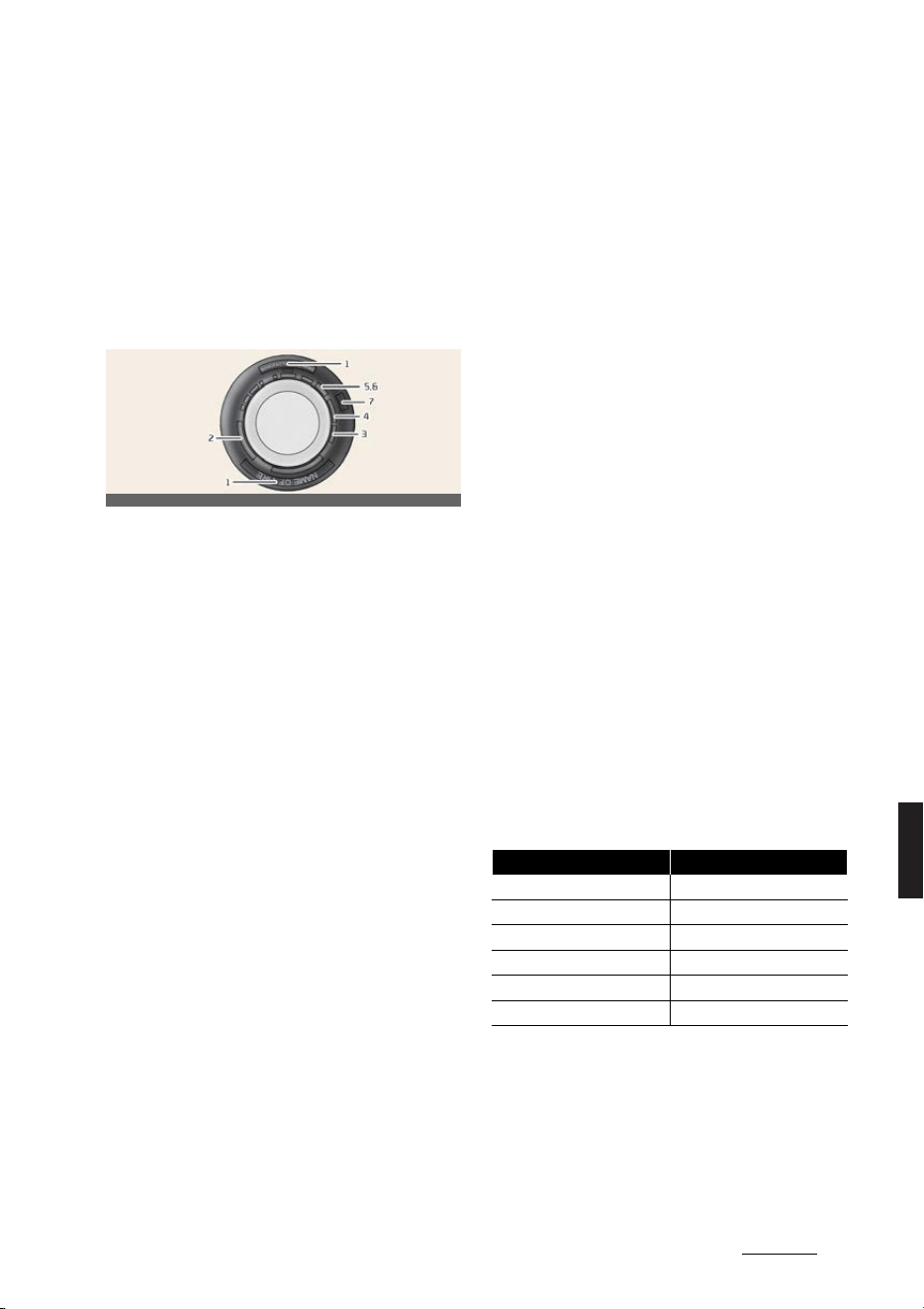
19
8
8
Maintenance Tires and wheels
visit an authorized Kia dealer/service
partner.
When you have new tires installed, make
sure they are balanced. This will increase
vehicle ride comfort and tire life. Addi
-
tionally, a tire should always be rebal
-
anced if it is removed from the wheel.
Tire sidewall labeling
This information identifies and describes
the fundamental characteristics of the
tire and also provides the tire identifica
-
tion number (TIN) for safety standard
certification. The TIN can be used to
identify the tire in case of a recall.
1. Manufacturer or brand name
Manufacturer or brand name is shown.
2. Tire size designation
A tire's sidewall is marked with a tire size
designation. You will need this informa
-
tion when selecting replacement tires for
your vehicle.
Example tire size designation:
(These numbers are provided as an
example only.)
P235/55R19 108T
235 - Tire width in millimeters.
55 - Aspect ratio. The tire's section
height as a percentage of its width.
R - Tire construction code (Radial).
19 - Rim diameter in inches.
108 - Load Index, a numerical code
associated with the maximum load the
tire can carry.
T - Speed Rating Symbol. See the speed
rating chart in this section for additional
information.
Wheel size designation
Wheels are also marked with important
information that you need if you ever
have to replace one. The following
explains what the letters and numbers in
the wheel size designation mean.
Example wheel size designation:
7.5JX19
7.5 - Rim width in inches.
J - Rim contour designation.
19 - Rim diameter in inches.
Tire speed ratings
The chart below lists many of the differ
-
ent speed ratings currently being used
for passenger car tires. The speed rating
is part of the tire size designation on the
sidewall of the tire. This symbol corre
-
sponds to that tire's designed maximum
safe operating speed.
3. Checking tire life (TIN: Tire
Identification Number)
Any tires that are over 6 years old, based
on the manufacturing date, should be
replaced by new ones. You can find the
manufacturing date on the tire sidewall,
OCV071010L
Speed Rating Symbol Maximum Speed
S 180 km/h (112 mph)
T 190 km/h (118 mph)
H 210 km/h (130 mph)
V 240 km/h (149 mph)
W 270 km/h (168 mph)
Y 300 km/h (186 mph)

Maintenance
208
Tires and wheels
displaying the DOT Code. The manufac
-
turing date is designated by the last four
digits (characters) of the DOT code.
DOT: XXXX XXXX OOOO
The front part of the DOT means a plant
code number, tire size and tread pattern
and the last four numbers indicate week
and year manufactured.
For example, DOT XXXX XXXX 1622 rep
-
resents that the tire was produced in the
16th week of 2022.
WARNING
Tires degrade over time, even when they
are not being used. Regardless of the
remaining tread, we recommend that
tires be replaced after approximately 6
years of normal service. Heat caused by
hot climates or frequent high loading
conditions can accelerate the aging pro
-
cess. Failure to follow this warning can
result in sudden tire failure, which could
lead to a loss of control and an accident
involving serious injury or death.
4. Tire ply composition and mate
-
rial
The number of layers or plies of rubber-
coated fabric in the tire. Tire manufac
-
turers also must indicate the materials in
the tire, which include steel, nylon, poly
-
ester, and others. The letter "R" means
radial ply construction; the letter "D"
means diagonal or bias ply construction;
and the letter "B" means belted-bias ply
construction.
5. Maximum permissible inflation
pressure
This number is the greatest amount of
air pressure that should be put in the
tire. Do not exceed the maximum per
-
missible inflation pressure. Refer to "Tire
specification and pressure label" on
page 9-8.
6. Maximum load rating
This number indicates the maximum
load in kilograms and pounds that can
be carried by the tire. When replacing
the tires on the vehicle, always use a tire
that has the same load rating as the fac
-
tory installed tire.
7. Uniform tire quality grading
Quality grades can be found where
applicable on the tire sidewall between
tread shoulder and maximum section
width.
For example:
TREADWEAR 200
TRACTION AA
TEMPERATURE A
WARNING
僅 The traction grade assigned to this
tire is based on straight ahead brak
-
ing traction tests, and does not
include acceleration, cornering,
hydroplaning, or peak traction char
-
acteristics.
僅 The temperature grade for this tire is
established for a tire that is properly
inflated and not overloaded. Exces
-
sive speed, under inflation, or exces
-
sive loading, either separately or in
combination, can cause heat build-up
in tire and sudden tire failure. This can
cause loss of vehicle control and seri
-
ous injury or death.

21
8
8
Maintenance Tires and wheels
Tread wear
The tread wear grade is a comparative
rating based on the wear rate of the tire
when tested under controlled conditions
on a specified government test course.
For example, a tire graded 150 would
wear one-and-a-half times (1½) as well
on the government course as a tire
graded 100.
The relative performance of tires
depends upon the actual conditions of
their use, however, and may depart sig
-
nificantly from the norm due to varia
-
tions in driving habits, service practices
and differences in road characteristics
and climate.
The tires available as standard or
optional equipment on your vehicle may
vary with respect to grade.
Traction - AA, A, B & C
The traction grades, from highest to low
-
est, are AA, A, B and C. Those grades
represent the tire's ability to stop on wet
pavement as measured under controlled
conditions on specified government test
surfaces of asphalt and concrete. A tire
marked C may have poor traction per
-
formance.
Temperature -A, B & C
The temperature grades are A (the high
-
est), B, and C, representing the tire's
resistance to the generation of heat and
its ability to dissipate heat when tested
under controlled conditions on a speci
-
fied indoor laboratory test wheel.
Sustained high temperature can cause
the material of the tire to degenerate
and reduce tire life, and excessive tem
-
perature can lead to sudden tire failure.
Grades B and A represent higher levels
of performance on the laboratory test
wheel than the minimum required by
law.
Low aspect ratio tire (if
equipped)
Low aspect ratio tires, whose aspect
ratio is lower than 50, are provided for
sporty looks.
Because the low aspect ratio tires are
optimized for handling and braking, it
may be more uncomfortable to ride in
and there is more noise compare with
normal tires.
CAUTION
僅 Because the sidewall of the low aspect
ratio tire is shorter than the normal,
the wheel and tire of the low aspect
ratio tire is easier to be damaged. So,
follow the instructions below.
- When driving on a rough road or
off road, drive cautiously because
tires and wheels may be damaged.
And after driving, inspect tires and
wheels.
- When passing over a pothole,
speed bump, manhole, or curb
stone, drive slowly so that the tires
and wheels are not damaged.
- If the tire is impacted, inspect the
tire condition or contact a profes
-
sional workshop. Kia recommends
to visit an authorized Kia dealer/
service partner.
- To prevent damage to the tire,
inspect the tire condition and pres
-
sure every 3,000 km (2,000 miles).
僅 It is not easy to recognize the tire
damage with your own eyes. But if
there is the slightest hint of tire dam
-
age, even though you cannot see the
tire damage with your own eyes, have
the tire checked or replaced because
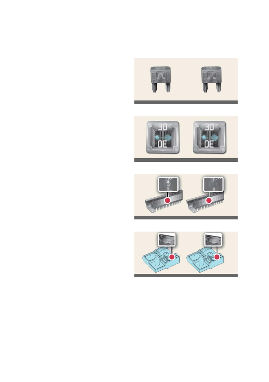
Maintenance
228
Fuses
the tire damage may cause air leak
-
age from the tire.
僅 If the tire is damaged by driving on a
rough road, off road, pothole, man
-
hole, or curb stone, it will not be cov
-
ered by the warranty.
僅 You can find out the tire information
on the tire sidewall.
Fuses
Blade type
Cartridge type
Multi fuse
BFT
* Left: Normal, Right: Blown
* The actual fuse/relay panel label may
differ.
Before replacing a blown fuse, discon
-
nect the negative battery cable.
If the electrical system does not work,
first check the driver's side fuse panel.
Always replace a blown fuse with one of
the same rating.
OCV071014L
OCV071015L
OCV071017L
OCV071018L
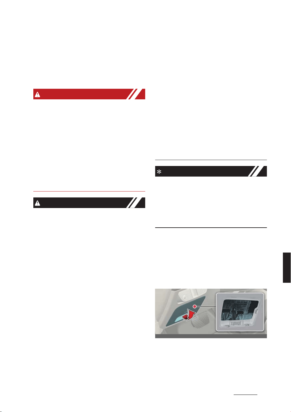
23
8
8
Maintenance Fuses
If the replacement fuse blows, this indi
-
cates an electrical problem. Avoid using
the system involved and immediately
consult a professional workshop. Kia
recommends to consult an authorized
Kia dealer/service partner.
WARNING
僅 Never replace a fuse with anything
but another fuse of the same rating.
僅 A higher capacity fuse could cause
damage and possibly a fire.
僅 Never install a wire or aluminum foil
instead of the proper fuse even as a
temporary repair. It may cause exten
-
sive wiring damage and a possible
fire.
僅 Do not arbitrarily modify or add-on
electric wiring of the vehicle.
CAUTION
僅 When replacing a blown fuse or relay
with a new one, make sure the new
fuse or relay fits tightly into the clips.
The incomplete fastening fuse or
relay may cause the vehicle wiring
and electric systems damage and a
possible fire.
僅 Do not remove fuses, relays and ter
-
minals fastened with bolts or nuts.
The fuses, relays and terminals may
be fastened incompletely, and it may
cause a possible fire. If fuses, relays
and terminals fastened with bolts or
nuts are blown, consult a professional
workshop. Kia recommends to consult
an authorized Kia dealer/service part
-
ner.
僅 Do not input any other objects except
fuses or relays into fuse/relay termi
-
nals such as a driver or wiring. It may
cause contact failure and system mal
-
function.
僅 Do not plug in screwdrivers or after
-
market wiring into the terminal origi
-
nally designed for fuse and relays
only. The electrical system and wiring
of the vehicle interior may be dam
-
aged or burned due to contact failure.
僅 If you directly connect the wire on the
taillight or replace the bulb which is
over the regulated capacity to install
trailers etc., the inner junction block
can get burned.
僅 Do not use a screwdriver or any other
metal object to remove fuses because
it may cause a short circuit and dam
-
age the system.
NOTICE
僅 When replacing fuse, press the EV
button to the OFF position and turn
off switches of all electrical devices
then remove battery (-) terminal.
僅 The actual fuse/relay panel label may
differ from equipped items.
Replacing inner panel fuse
Operation
1. Press the EV button to the OFF posi
-
tion and turn all other switches off.
2. Open the fuse panel cover.
3. Pull the suspected fuse straight out.
Use the removal tool (1) provided in
the main fuse box in the motor com
-
partment.
OCV071019L
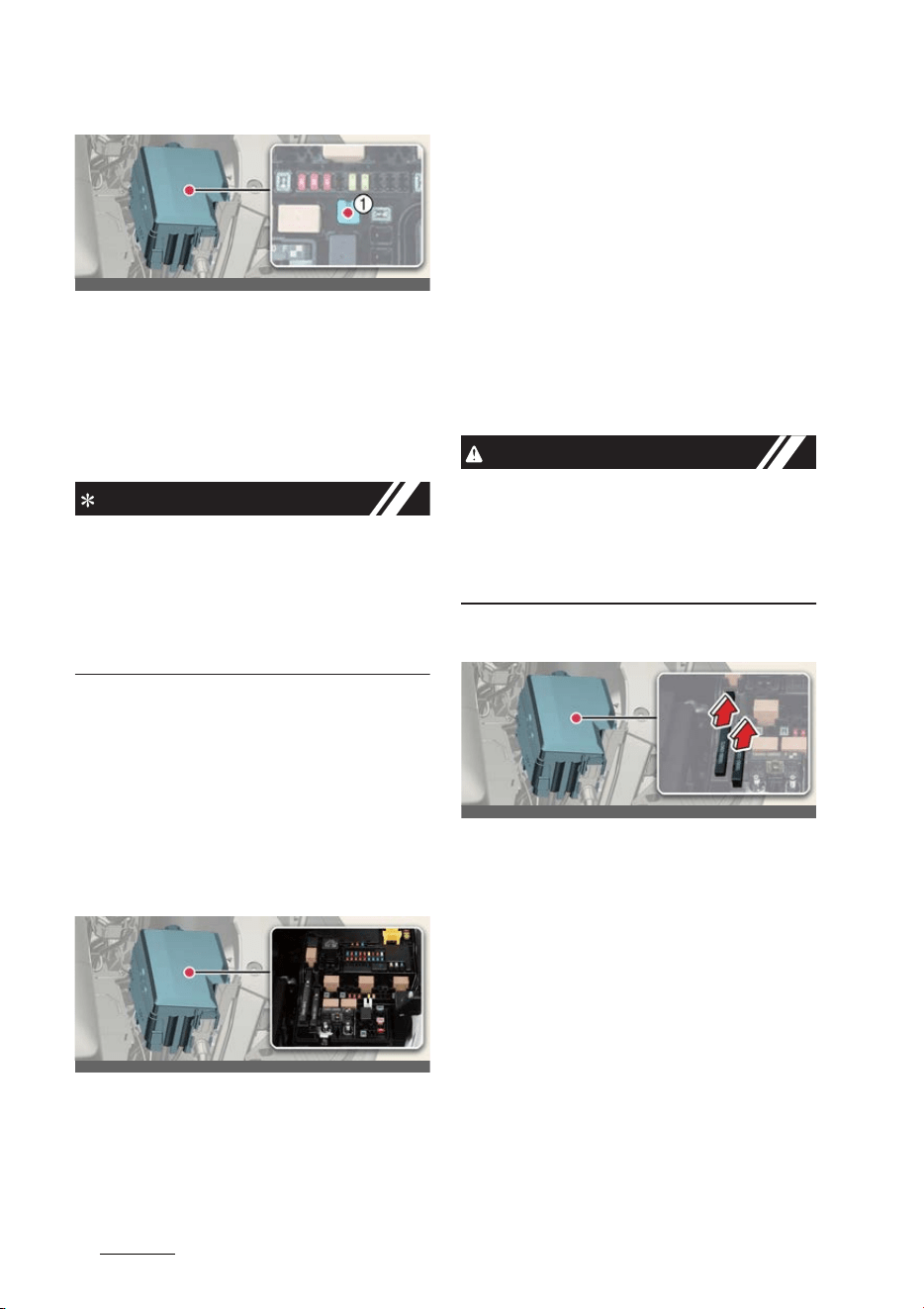
Maintenance
248
Fuses
4. Check the removed fuse; replace it if
it is blown. Spare fuses are provided
in the instrument fuse panel (or in the
motor compartment fuse panel).
5. Push in a new fuse of the same rating,
and make sure it fits tightly in the
clips.
INFORMATION
If the headlights or taillights, stoplights,
day time running lights (DRL) do not
work and the fuses are OK, consult a
professional workshop. Kia recommends
to consult an authorized Kia dealer/ser
-
vice partner.
Replacing motor room fuse
Operation
僅 Press the EV button to the OFF posi
-
tion and turn all other switches off.
僅 Remove the fuse panel cover by
pressing the tab and pulling the cover
up.
When the blade type fuse is discon
-
nected, remove it by using the clip
designed for changing fuses located
in the motor room fuse box. Upon
removal, securely insert reserve fuse
of equal quantity.
僅 Check the removed fuse; replace it if
it is blown. To remove or insert the
fuse, use the fuse puller in the motor
compartment fuse panel.
僅 Push in a new fuse of the same rating,
and make sure it fits tightly in the
clips. If it fits loosely, consult a profes
-
sional workshop. Kia recommends to
consult an authorized Kia dealer/ser
-
vice partner.
CAUTION
After checking the fuse panel in the
motor compartment, securely install the
fuse panel cover through the audible
clicking sound. If not, electrical failures
may occur from water contact.
Replacing main fuse (multi fuse)
Operation
僅 Turn off the vehicle.
僅 Disconnect the negative battery cable.
僅 Remove the nuts shown in the picture
above.
僅 Replace the fuse with a new one of
the same rating.
僅 Reinstall in the reverse order of
removal.
OCV071020L
OCV071066L
OCV071021L

25
8
8
Maintenance Fuses
CAUTION
Visually inspect the battery cap for
secure closing. If the battery cap is not
securely latched, the electrical system
may be damaged to due influx of mois
-
ture into the system.
NOTICE
僅 The electronic system may not func
-
tion correctly even when the motor
room and internal fuse box's individ
-
ual fuses are not disconnected. In
such case the cause of the problem
may be disconnection of the main
fuse (BFT type), which is located
inside the positive battery terminal (+)
cap. Since the main fuse is designed
more intricately than other parts, visit
a professional workshop. Kia recom
-
mends to visit the nearest authorized
Kia dealer/service partner.
僅 If the multi fuse is blown, consult a
professional workshop. Kia recom
-
mends to consult an authorized Kia
dealer/service partner.
Fuse/relay panel description
Inside the fuse/relay panel covers, you
can find the fuse/relay label describing
fuse/relay name and capacity.
NOTICE
Not all fuse panel descriptions in this
manual may be applicable to your vehi
-
cle. It is accurate at the time of printing.
When you inspect the fuse panel in your
vehicle, refer to the fuse panel label.
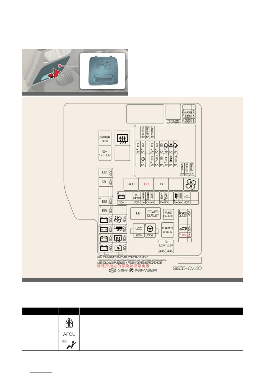
Maintenance
268
Fuses
Driver's side fuse panel
ICU Junction Block
OCV071022L
Fuse Name Symbol Fuse Rating Circuit Protected
CHILD LOCK 15A Child Lock Relay, Child Unlock Relay
AFCU 10A AFCU
A/BAG IND 7.5A Overhead Console
OCV072024L
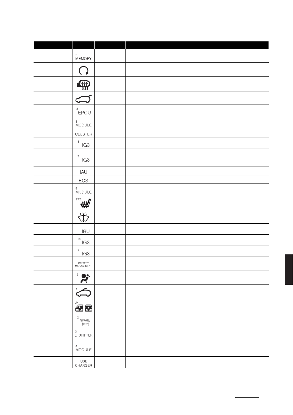
27
8
8
Maintenance Fuses
MEMORY2 10A
Fuse - MEMORY2, Mood Lamp Unit, Crash Pad Mood Lamp LH/RH, ADP,
Head-Up Display, ADS Unit
START 7.5A VCU, IBU (Integrated Body Control Unit)
HEATED MIRROR 10A Driver/Passenger Outside Mirror Unit
TAILGATE OPEN 15A Tailgate Latch
EPCU 3 10A Rear Inverter
MODULE3 7.5A
Multifunction Switch, IBU (Integrated Body Control Unit), Stop Lamp Switch,
Driver Door Module
CLUSTER 7.5A Head-Up Display, Instrument Cluster
IG3 8 10A V2L Unit, ICCU, VCMS, Rear Electronic Oil Pump, CDM
IG3 7 10A
In-car Temperature Sensor, Audio/Video & Navigation Head Unit, A/C PTC
(Positive Temperature Coefficient) Heater, A/C Control Module, Instrument
Cluster
IAU 10A Driver/Passenger Door Outside Handle
ECS 15A Electronics Control Suspension
MODULE8 10A Driver/Passenger Power Seat Module, Driver/Passenger Manual Seat Switch
S/HEATER FRT 20A Front Air Ventilation Seat Control Module, Front Seat Warmer Control Module
WASHER 15A Multifunction Switch
IBU2 7.5A IBU (Integrated Body Control Unit)
IG3 10 10A SCU (System Control Unit), Rear Inverter, BMU
IG3 9 10A Not Used
BATTERY MAN
-
AGEMENT
10A BMU
AIR BAG2 10A SRS (Supplemental Restraint System) Control Module
SUNROOF1 25A Sunroof Motor
P/WINDOW LH 25A
Driver Safety Power Window Module (LHD), Passenger Safety Power Window
Module (RHD), Rear Power Window Switch LH
SPARE2 (IG2) 15A Not Used
E-SHIFTER 3 10A Electronic ATM (Automatic Transmission) Shift Dial
MODULE4 10A
Front/Rear Corner Radar LH/RH, Front/Rear Inverter, ADAS Driving ECU, VESS
(Virtual Engine Sound System) Unit, Front Radar, Front View Camera, ADAS
Parking ECU, Console Upper Cover Switch
USB CHARGER 15A Driver/Passenger Seat USB Charger, Front Console USB Charger #1/#2
Fuse Name Symbol Fuse Rating Circuit Protected
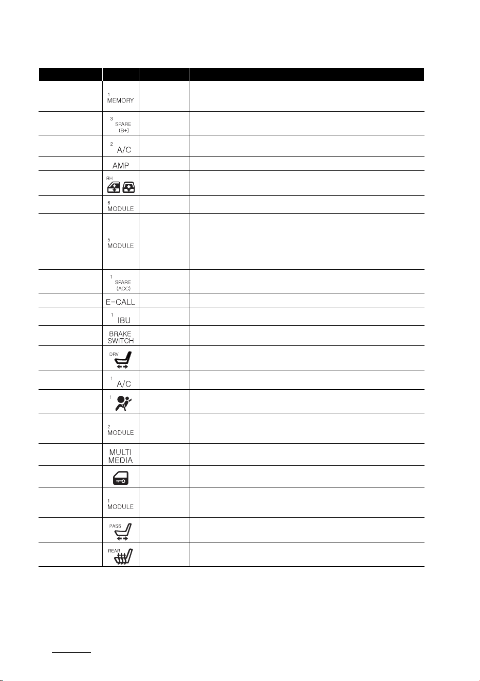
Maintenance
288
Fuses
MEMORY1 15A
Fuse - MEMORY2, Instrument Cluster, A/C Control Module, Console Mood
Lamp (Upper/Lower), Console Floor Switch, Driver/Passenger Door Mood
Lamp, Rear Door Mood Lamp LH/RH
SPARE3 (B+) 10A Not Used
A/C2 10A
A/C Control Module, High Pressure Valve, Refrigerants Valve #1/#2 P/R Junc
-
tion Block (Blower Relay), BSA Chiller #1, A/C Coolant Valve
AMP 25A AMP (Amplifier)
P/WINDOW RH 25A
Passenger Safety Power Window Module (LHD), Driver Safety Power Window
Module (RHD), Rear Power Window Switch RH
MODULE6 7.5A IBU (Integrated Body Control Unit)
MODULE5 10A
Data Link Connector, Electro Chromic Mirror, E-CALL Unit, ADP, Audio/Video &
Navigation Head Unit, Crash Pad Switch, Head Lamp LH/RH, AMP (Amplifier),
Smart Phone Wireless Charger, Driver/Passenger Power Seat Module, Front Air
Ventilation Seat Control Module, Front Seat Warmer Control Rear Seat Warmer
Control Module, Console Floor Switch, Auto Head Lamp Leveling Device Mod
-
ule, IFS (Intelligent Front-Lighting System) Module
SPARE1 (ACC) 10A Not Used
E-CALL 10A E-CALL Unit
IBU1 15A IBU (Integrated Body Control Unit)
BRAKE SWITCH 10A Stop Lamp Switch, IBU (Integrated Body Control Unit)
P/SEAT DRV 30A
Driver Power Seat Switch, Driver Power Seat Module (With IMS (Integrated
memory system))
A/C1 7.5A A/C Control Module
AIR BAG1 15A SRS (Supplemental Restraint System) Control Module
MODULE2 10A
AMP (Amplifier), ADP, P/E Junction Block (Power Outlet Relay), IBU (Integrated
Body Control Unit), E-CALL Unit, ADAS Unit, Audio/Video & Navigation Key
-
board, Audio/Video & Navigation Head Unit
MULTIMEDIA 15A Audio/Video & Navigation Head Unit
DOOR LOCK 20A Door Lock Relay, Door Unlock Relay, Dead Lock Relay
MODULE1 10A
Hazard Lamp Switch, Multifunction Switch, Data Link Connector, Rain Sensor,
UIP Siren, UIP Sensor, PTG Unit, Driver Door Module, Driver/Passenger Outside
Mirror Unit
P/SEAT PASS 30A Passenger Power Seat Switch, Passenger Power Seat Module
S/HEATER RR 25A Rear Seat Warmer Control Module
Fuse Name Symbol Fuse Rating Circuit Protected
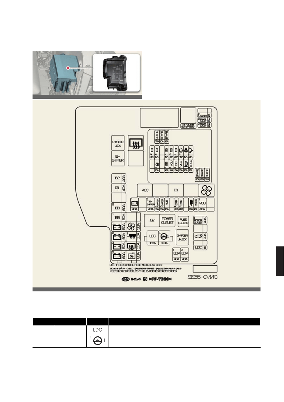
29
8
8
Maintenance Fuses
Motor compartment fuse panel
Circuit (P/R Junction Block)
OCV071067L
Fuse Name Symbol Fuse Rating Circuit Protected
MULTI
FUSE-1
LDC 180A P/R Junction (Fuse: P/OUTLET1, T/GATE, EOP1, EOP2)
MDPS1 100A
MDPS Unit
* MDPS is the same as EPS (Electric Power Steering).
OCV071024L
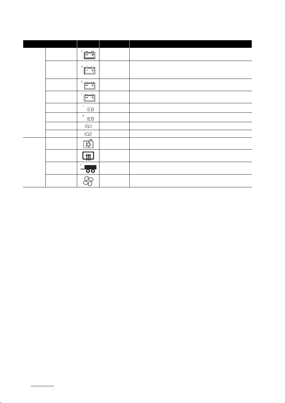
Maintenance
308
Fuses
MULTI
FUSE-3
B+5 60A
PCB Block (IG3 Main Relay, Fuse: WIPER1, EPCU1, B/ALARM, HORN,
VCU2)
B+3 60A
ICU Junction Block (Fuse: CHILD LOCK, AFCU, TAILGATE OPEN,
EPCU 3, MODULE8, S/HEATER FRT, SUNROOF1, P/WINDOW LH,
AMP, P/WINDOW RH, P/SEAT DRV, P/SEAT PASS, S/HEATER RR)
B+2 60A ICU Junction Block (IPS1, PS6, IPS8, IPS9, IPS10)
B+1 50A ICU Junction Block (IPS2, IPS3, IPS5, IPS7, IPS13)
IEB1 60A IEB Unit
IEB2 60A IEB Unit
IG1 40A P/R Junction Block (ACC Relay, IG1 Relay)
IG2 40A P/R Junction Block (IG2 Relay)
MULTI
FUSE-2
C/FAN 80A Cooling Fan Motor
RR HTD 50A P/R Junction Block (Rear Heated Relay)
TRAILER1 50A Trailer Connector Unit
BLOWER 50A P/R Junction Block (Blower Relay)
Fuse Name Symbol Fuse Rating Circuit Protected
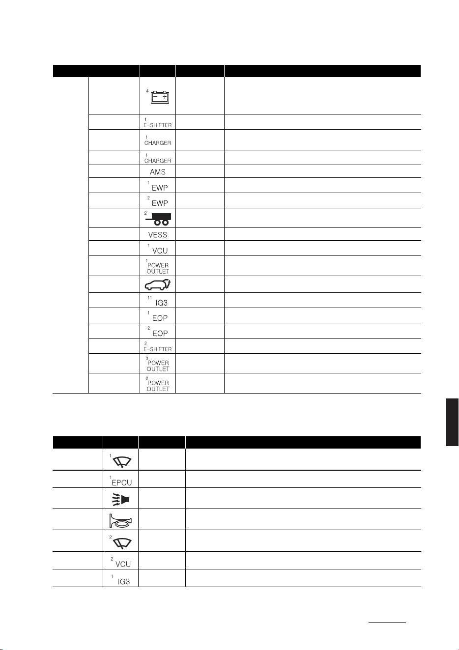
31
8
8
Maintenance Fuses
PCB Block
FUSE
B+4 40A
ICU Junction Block (Long Term Load Latch Relay, Fuse: IAU, ECS,
BATTERY MANAGEMENT, AIR BAG2, MEMORY1, SPARE3 (B+), A/C2,
E-CALL, IBU1, BRAKE SWITCH, MULTIMEDIA, DOOR LOCK, MOD
-
ULE1)
E-SHIFTER1 40A P/R Junction Block (E-Shifter Relay, Fuse: E-SHIFTER2)
CHARGER1 10A
P/R Junction Block (Charger Lock Relay, Charger Unlock Relay),
ICCU, VCMSCDM
CHARGER2 10A CDM
AMS 10A 12V Battery Sensor
EWP1 20A Electronic Water Pump #1
EWP2 20A Electronic Water Pump #2
TRAILER2 20A Trailer Connector Unit
VESS 10A VESS Unit
VCU1 40A VCU
P/OUTLET1 40A Power Outlet Relay
T/GATE 30A PTG Unit
IG3 11
20A ICU Junction Block (IG3 8, IG3 7, IG3 10, IG3 9)
EOP1 40A Rear Electronic Oil Pump
EOP2 40A Front Electronic Oil Pump (4WD)
E-SHIFTER2 10A E-Shifter Relay, SCU, Electronic ATM Shift Dial
P/OUTLET3 20A Rear Power Outlet
P/OUTLET2 20A Front Power Outlet
Fuse Name Symbol Fuse Rating Circuit Protected
WIPER1 25A PCB (Printed Circuit Board) Block (Wiper Main Relay)
EPCU1 15A Front Inverter (4WD)
B/ALARM 10A PCB (Printed Circuit Board) Block (Burglar Alarm Horn Relay)
HORN 15A PCB (Printed Circuit Board) Block (Horn Relay)
WIPER2 7.5A IBU (Integrated Body Control Unit)
VCU2 15A VCU
IG3 1 20A ICU Junction Block (Fuse: IG3 8, IG3 7, IG3 10, IG3 9)
Fuse Name Symbol Fuse Rating Circuit Protected
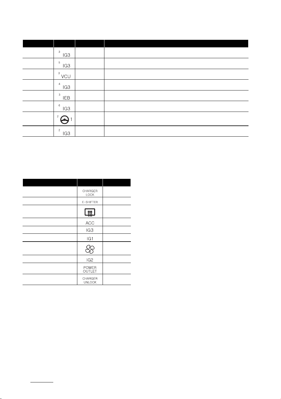
Maintenance
328
Fuses
Relay
Refer to the following table for the relay
type.
IG3 3 15A Electronic Water Pump
IG3 5 10A BMS (Battery Management System) Coolant 3Way Valve
VCU3 10A VCU
IG3 4 10A Electronic Water Pump #1, #2, Electronic A/C Compressor
IEB3 10A IEB Unit
IG3 6 10A Cooling Fan Motor, Front Electronic Oil Pump (4WD)
MDPS2 10A
MDPS Unit
* MDPS is the same as EPS (Electric Power Steering).
IG3 2 15A Front Inverter (4WD), VCU
Fuse Name Symbol Fuse Rating Circuit Protected
Relay Name Symbol TYPE
Charger Lock Relay MICRO
E-Shifter Relay MICRO
Rear Heated Relay MINI
ACC Relay MICRO
IG3 Relay MICRO
IG1 Relay MICRO
Blower Relay MICRO
IG2 Relay MICRO
Power Outlet Relay MICRO
Charger Unlock Relay MICRO

33
8
8
Maintenance Lamps
Lamps
Bulb replacement precautions
Turn off the vehicle at a safe place,
firmly apply the side brake and take out
the battery's negative (-) terminal. Use
only the bulbs of the specified wattage.
Lamp part malfunction due to
network failure
Lamp part malfunction may be caused
by network failure or vehicle electrical
control system malfunction. If there is a
problem, have the system serviced by a
professional workshop. Kia recommends
to visit an authorized Kia dealer/service
partner.
Lamp part malfunction due to
electrical control system stabili
-
zation
A normally functioning lamp may flicker
momentarily. This momentary occur
-
rence is due to stabilization unction of
the vehicle's electrical on control system.
If the lamp soon returns to normal, the
vehicle does not require service.
However, if the lamp goes out after the
momentary flickering, or the flickering
continues, have the system serviced by
a professional workshop. Kia recom
-
mends to visit an authorized Kia dealer/
service partner.
WARNING
僅 Prior to working on the light, firmly
apply the parking brake, press the EV
button to the OFF position and turn
off the lights to avoid sudden move
-
ment of the vehicle and burning your
fingers or receiving an electric shock.
僅 Be sure to replace the burned out
bulb with one of the same wattage
rating. Otherwise, it may cause exten
-
sive wiring damage and possible fire.
- Be aware the bulbs may be hot and
may burn your fingers.
CAUTION
僅 If you don't have necessary tools, the
correct bulbs and the expertise, con
-
sult a professional workshop. Kia rec
-
ommends to consult an authorized
Kia dealer/service partner.
僅 In many cases, it is difficult to replace
vehicle light bulbs because other
parts of the vehicle must be removed
before you can get to the bulb. This is
especially true if you have to remove
the headlight assembly to get to the
bulb(s). Removing/installing the head
-
light assembly can result in damage
to the vehicle.
僅 Removing/installing the headlamp
assembly can result in damage to the
vehicle. Use only Kia Genuine Parts or
those of an equivalent standard part.
If not, it may lead to blowing a fuse or
other wiring damages.
僅 Do not install extra lamps or LED to
the vehicle. If supplementary lights
are installed, it may lead to lamp mal
-
function and flickering of the lights. In
addition, the fuse box and other wir
-
ing may be damaged.
NOTICE
僅 If the light bulb or lamp connector is
removed from an operating lamp acti
-
vated by electricity, the fuse box's
electronic device may scan it as a
malfunction. Therefore, a lamp mal
-
function history may be recorded in
Diagnostic Trouble Code (DTC) in the
fuse box.
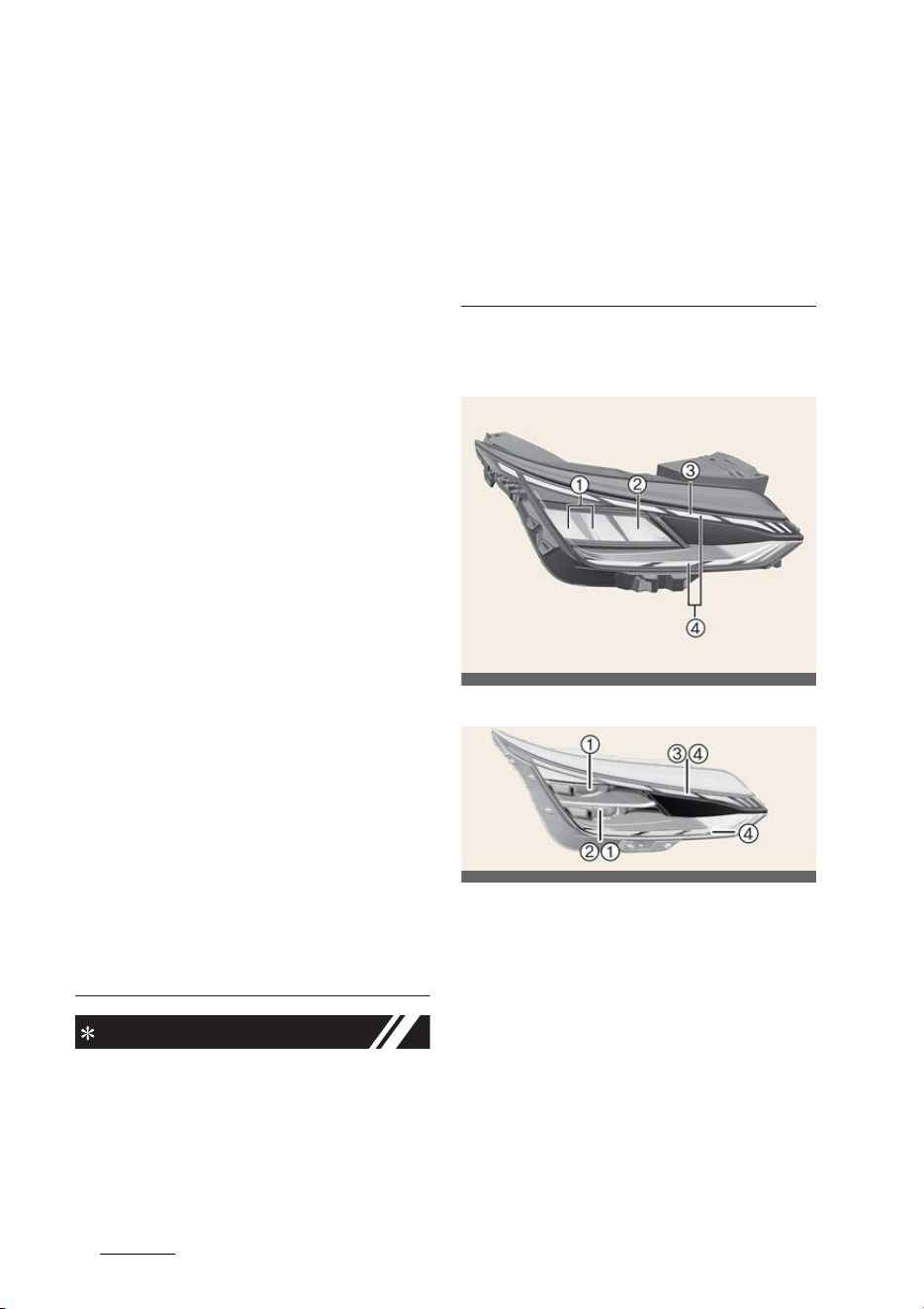
Maintenance
348
Lamps
僅 It is normal for an operating lamp may
blink temporarily. Since this occur
-
rence is due stabilization function of
the vehicle's electronic control device,
if the lamp lights up normally after
temporary blinking, there is no prob
-
lem in the vehicle.
However, if the lamp continues to
blink several times or turn off com
-
pletely, there may be an error in the
vehicle's electronic control device. In
this case, have the vehicle checked by
a professional workshop immedi
-
ately. Kia recommends to visit an
authorized Kia dealer/service partner.
僅 After an accident or after the head
-
light assembly is reinstalled, have the
headlight aiming adjusted by a pro
-
fessional workshop. Kia recommends
to visit an authorized Kia dealer/ser
-
vice partner.
僅 After driving in heavy rain or washing,
headlamp and taillamp lenses could
appear frosty. This condition is caused
by the temperature difference
between the lamp inside and outside.
This is similar to the condensation on
your windows inside your vehicle
during the rain and doesn't indicate a
problem with your vehicle. If the water
leaks into the lamp bulb circuitry,
have the vehicle checked by a profes
-
sional workshop. Kia recommends to
visit an authorized Kia dealer/service
partner.
NOTICE
Traffic Change (For Europe)
The low beam light distribution is asym
-
metric. If you go abroad to a country
with opposite traffic direction, this asym
-
metric part will dazzle oncoming car
driver. To prevent dazzle, ECE regulation
demand several technical solutions (ex.
automatic change system, adhesive
sheet, down aiming). This headlamps are
designed not to dazzle opposite drivers.
So, you need not change your head
-
lamps in a country with opposite traffic
direction.
Light position (Front)
Head lamp – Type A
Head lamp – Type B
1
Headlamp (Low) (LED type)
2
Headlamp (High) (LED type)
3
Front turn signal lamp (LED type)
4
Day time running lamp/Position lamp
(LED type)
OCV071026L
OCV071027L
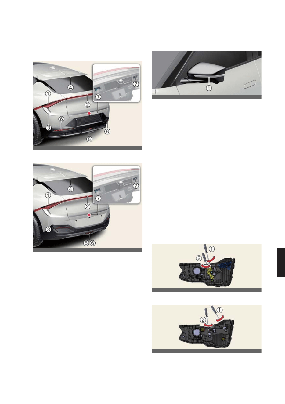
35
8
8
Maintenance Lamps
Light position (Rear)
Type A
Type B
1
Stop and tail lamp (LED type)
2
Tail lamp (LED type)
3
Rear turn signal lamp (LED type)
4
High mounted stop lamp (LED type)
5
Backup lamp (LED type)
6
Rear fog lamp (LED type)
7
License plate lamp (LED type)
Light position (Side)
1
Side repeater lamp (LED type)
Replacing lights
If a lamp does not operate, have your
vehicle checked by a professional work
-
shop. Kia recommends to visit an autho
-
rized Kia dealer/service partner.
The LED lamp cannot be replaced as a
single unit because it is an integrated
unit. The LED lamp has to be replaced
with the unit.
A skilled technician should check or
repair the LED lamp, for it may damage
related parts of the vehicle.
Headlamp aiming (for Europe)
Headlamp aiming
Type A
Type B
OCV071028L
OCV071068L
OCV071031L
OCV071044L
OCV071045L

Maintenance
368
Lamps
Operation
僅 Inflate the tires to the specified pres
-
sure and remove any loads from the
vehicle except the driver, spare tire,
and tools.
僅 The vehicle should be placed on a flat
floor.
僅 Draw vertical lines (Vertical lines pass
-
ing through respective head lamp
centers) and a horizontal line (Hori
-
zontal line passing through center of
head lamps) on the screen.
僅 With the head lamp and battery in
normal condition, aim the head lamps
so the brightest portion falls on the
horizontal and vertical lines.
僅 To aim the low beam left or right, turn
the screwdriver (1) clockwise or coun
-
terclockwise. To aim the low beam up
or down, turn the screwdriver (2)
clockwise or counterclockwise.
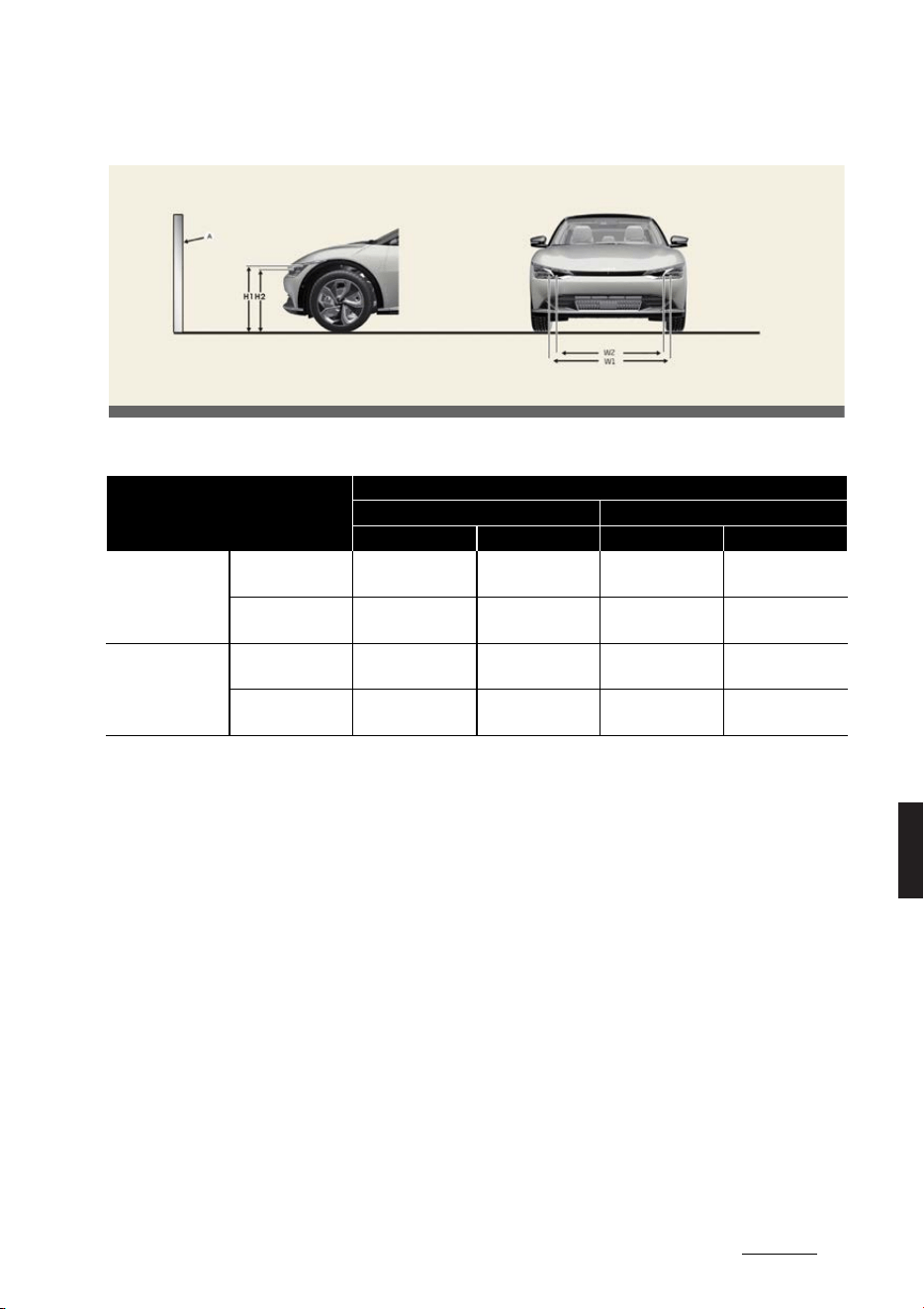
37
8
8
Maintenance Lamps
Aiming point
* A: Screen
Vehicle condition
Head lamp (LED type)
Ground Height Distance between lamps
H1 (LOW) H2 (HIGH) W1 (LOW) W2 (HIGH)
without driver
[mm (in)]
Type A
708
(27.9)
698
(27.5)
1,610
(63.4)
1,416
(55.8)
Type B
734
(28.9)
679
(26.7)
1,572
(61.9)
1,526
(60.5)
with driver
[mm (in)]
Type A
698
(27.5)
688
(27.1)
1,610
(63.4)
1,416
(55.8)
Type B
724
(28.5)
669
(26.3)
1,572
(61.9)
1,526
(60.5)
OCV071046L
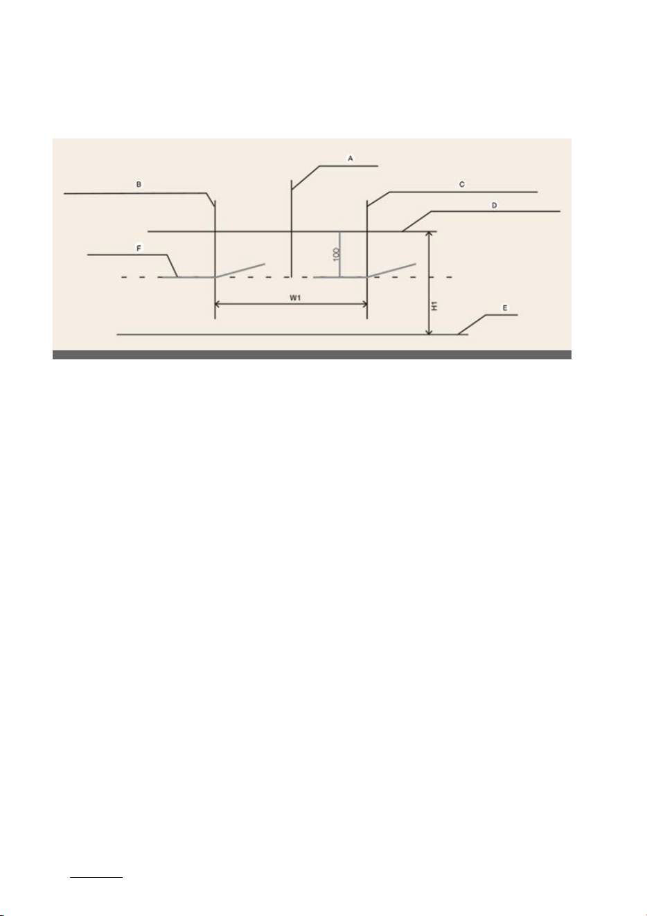
Maintenance
388
Lamps
Head lamp low beam (LHD Vehicle)
Based on 10m screen
僅A: Vehicle axis
僅 B: Vertical line of the left head lamp bulb center
僅 C: Vertical line of the right head lamp bulb center
僅 D: Horizontal line of head lamp bulb center
僅E: Ground
僅 F: Cut-Off line
Operation
僅 Turn the low beam on without driver aboard.
僅 The cut-off line should be projected in the cut-off line shown in the picture.
僅 When aiming the low beam, vertical aiming should be adjusted after adjusting the
horizontal aiming.
僅 Disengage the parking brake and put the gear in N (Neutral), in addition, if head
-
lamp leveling device is equipped, adjust the headlamp leveling device switch to '0'.
OCV071055L
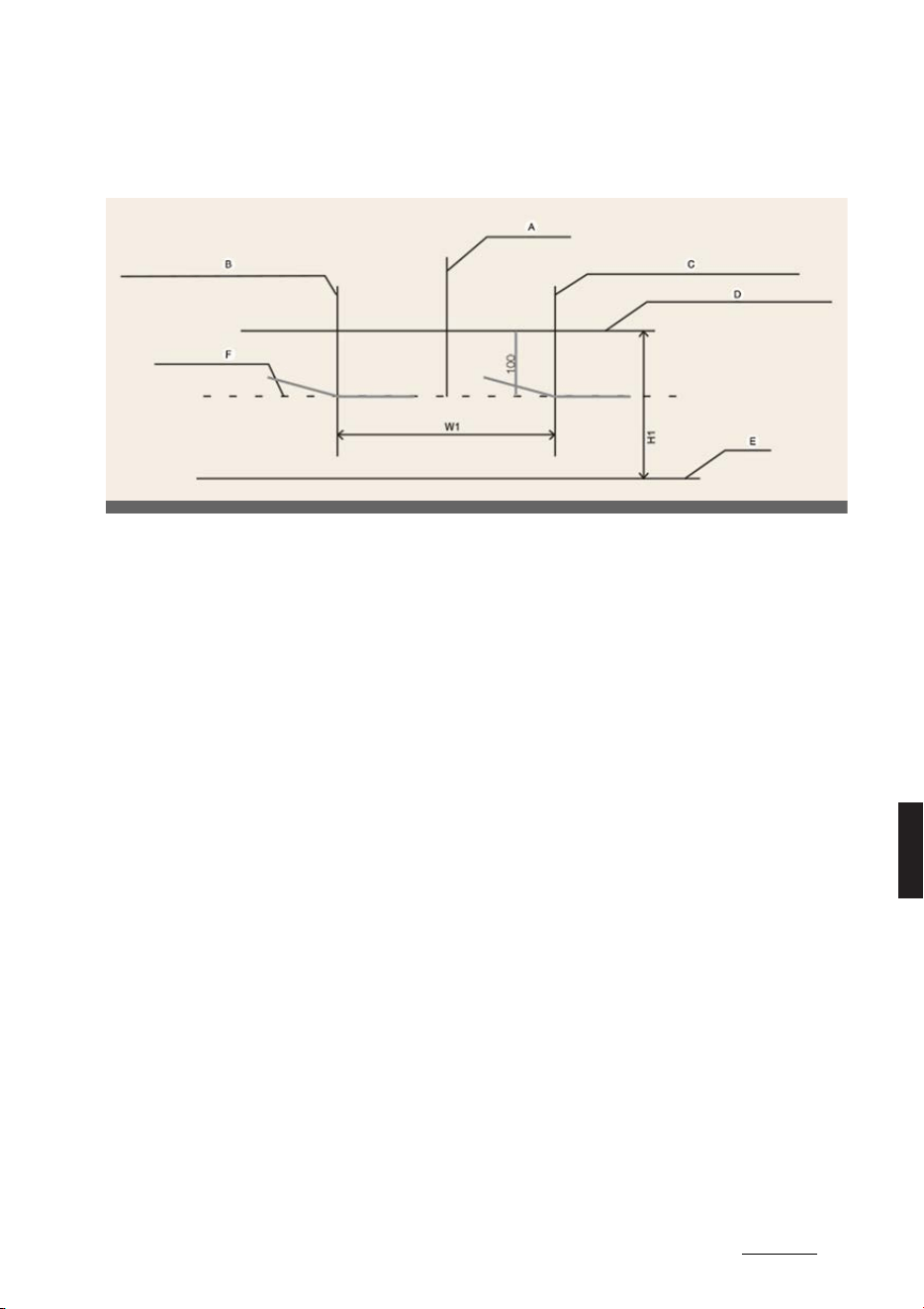
39
8
8
Maintenance Lamps
Head lamp low beam (RHD Vehicle)
Based on 10m screen
僅A: Vehicle axis
僅 B: Vertical line of the left head lamp bulb center
僅 C: Vertical line of the right head lamp bulb center
僅 D: Horizontal line of head lamp bulb center
僅E: Ground
僅 F: Cut-Off line
Operation
僅 Turn the low beam on without driver aboard.
僅 The cut-off line should be projected in the cut-off line shown in the picture.
僅 When aiming the low beam, vertical aiming should be adjusted after adjusting the
horizontal aiming.
僅 Disengage the parking brake and put the gear in N (Neutral), in addition, if head
-
lamp leveling device is equipped, adjust the headlamp leveling device switch to '0'.
OCV071056L

Maintenance
408
Appearance care
Appearance care
Exterior care
Exterior general caution
Read all warning and caution statements
that appear on the label and follow the
label directions when using any chemi
-
cal cleaner or polish.
NOTICE
If you park the vehicle around a stainless
signboard or windshield building etc.,
the plastic exterior trim (bumper, spoiler,
garnish, lamp, outside mirror etc.) may
be damaged by reflected sunlight from
the external structure. To avoid damag
-
ing the plastic exterior trim, park the
vehicle away from the areas where the
reflected light may occur or use a vehi
-
cle cover. (Depending on the vehicle, the
type of exterior trim applied such as
spoiler may differ.)
Finish maintenance
Washing
To help protect your vehicle's finish from
rust and deterioration, wash it thor
-
oughly and frequently at least once a
month with lukewarm or cold water.
If you use your vehicle for off-road driv
-
ing, you should wash it after each off-
road trip. Pay special attention to the
removal of any accumulation of salt, dirt,
mud, and other foreign materials. Make
sure the drain holes in the lower edges
of the doors and rocker panels are kept
clear and clean. Insects, tar, tree sap,
bird droppings, industrial pollution and
similar deposits can damage your vehi
-
cle's finish if not removed immediately.
Even prompt washing with plain water
may not completely remove all these
deposits. A mild soap, safe for use on
painted surfaces, may be used. After
washing, rinse the vehicle thoroughly
with lukewarm or cold water. Do not
allow soap to dry on the finish.
WARNING
After washing the vehicle, test the
brakes while driving slowly to see if they
have been affected by water. If braking
performance is impaired, dry the brakes
by applying them lightly while maintain
-
ing a slow forward speed.
CAUTION
僅 Do not use strong soap, chemical
detergents or hot water, and do not
wash the vehicle in direct sunlight or
when the body of the vehicle is warm.
僅 Be careful when washing the side win
-
dows of your vehicle. Especially, with
high-pressure water, water may leak
through the windows and wet the
interior.
僅 To prevent damage to the plastic
parts and lamps, do not clean with
chemical solvents or strong deter
-
gents.
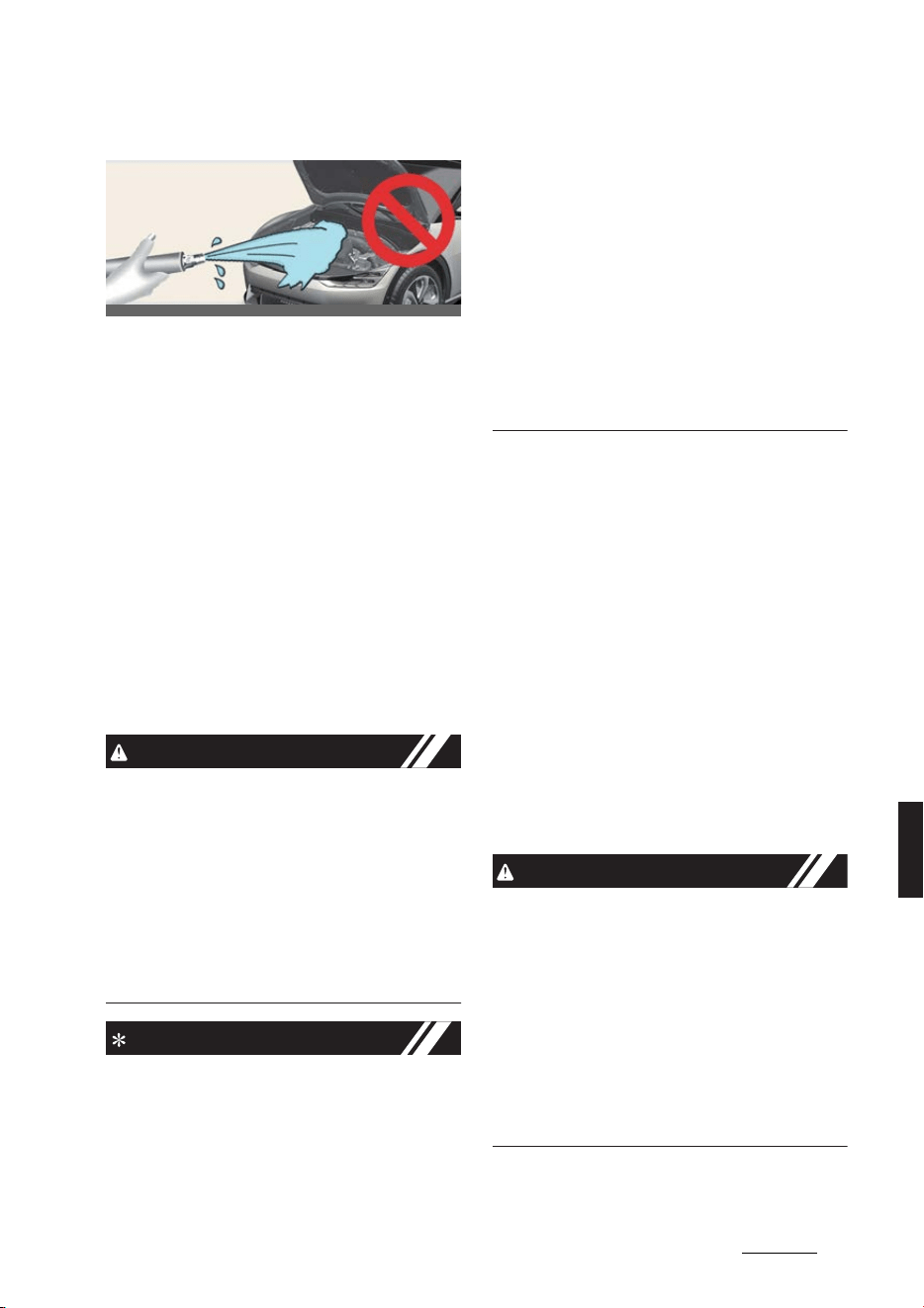
41
8
8
Maintenance Appearance care
High-pressure washing
僅 When using high-pressure washers,
make sure to maintain sufficient dis
-
tance from the vehicle.
Insufficient clearance or excessive
pressure can lead to component dam
-
age or water penetration.
僅 Do not spray the camera, sensors or
its surrounding area directly with a
high pressure washer. Shock applied
from high pressure water may cause
the device to not operate normally.
僅 Do not bring the nozzle tip close to
boots (rubber or plastic covers) or
connectors as they may be damaged
if they come into contact with high
pressure water.
CAUTION
僅 Water washing in the motor compart
-
ment including high pressure water
washing may cause the failure of elec
-
trical circuits located in the motor
compartment.
僅 Never allow water or other liquids to
come in contact with electrical/elec
-
tronic components inside the vehicle
as this may damage them.
NOTICE
Matte paint finish vehicle (if
equipped)
Automatic car wash which uses rotating
brushes should not be used as this can
damage the surface of your vehicle. A
steam cleaner which washes the vehicle
surface at high temperature may result
the oil to adhere and leave stains that is
difficult to remove.
Use a soft cloth (e.g. microfiber towel or
sponge) when washing your vehicle and
dry with a microfiber towel. When you
hand wash your vehicle, you should not
use a cleaner that finishes with wax. If
the vehicle surface is too dirty (sand,
dirt, dust, contaminant, etc.), clean the
surface with water before washing the
car.
Waxing
Wax the vehicle when water will no lon
-
ger bead on the paint.
Always wash and dry the vehicle before
waxing. Use a good quality liquid or
paste wax, and follow the manufac
-
turer's instructions. Wax all metal trim to
protect it and to maintain its luster.
Removing oil, tar, and similar materials
with a spot remover will usually strip the
wax from the finish. Be sure to re-wax
these areas even if the rest of the vehicle
does not yet need waxing. Do not apply
wax on embossed unpainted unit, as it
may tarnish the unit.
CAUTION
僅 Wiping dust or dirt off the body with a
dry cloth will scratch the finish.
僅 Do not use steel wool, abrasive clean
-
ers, acid detergents or strong deter
-
gents containing high alkaline or
caustic agents on chrome-plated or
anodized aluminum parts. This may
result in damage to the protective
coating and cause discoloration or
paint deterioration.
OCV071047L

Maintenance
428
Appearance care
NOTICE
Matte paint finish vehicle (if
equipped)
Do not use any polish protector such as
a detergent, an abrasive and a polish. In
case wax is applied, remove the wax
immediately using a silicon remover and
if any tar or tar contaminant is on the
surface use a tar remover to clean. How
-
ever, be careful not to apply too much
pressure on the painted area.
Finish damage repair
Deep scratches or stone chips in the
painted surface must be repaired
promptly. Exposed metal will quickly rust
and may develop into a major repair
expense.
NOTICE
僅 If your vehicle is damaged and
requires any metal repair or replace
-
ment, be sure the body shop applies
anti-corrosion materials to the parts
repaired or replaced.
僅 Matte paint finish vehicle (if
equipped)
In case of matte paint finish vehicles,
it is impossible to modify only the
damaged area and repair of the whole
part is necessary. If the vehicle is
damaged and painting is required, we
recommend that you have your vehi
-
cle maintained and repaired by an
authorized Kia dealer/service partner.
Take extreme care, as it is difficult to
restore the quality after the repair.
Bright-metal maintenance
僅 To remove road tar and insects, use a
tar remover, not a scraper or other
sharp object.
僅 To protect the surfaces of bright
metal parts from corrosion, apply a
coating of wax or chrome preserva
-
tive and rub to a high luster.
僅 During winter weather or in coastal
areas, cover the bright metal parts
with a heavier coating of wax or pre
-
servative. If necessary, coat the parts
with non-corrosive petroleum jelly or
other protective compound.
Underbody maintenance
Corrosive materials used for ice and
snow removal and dust control may col
-
lect on the underbody. If these materials
are not removed, accelerated rusting
can occur on underbody parts such as
the frame, floor pan, even though they
have been treated with rust protection.
Thoroughly flush the vehicle underbody
and wheel openings with lukewarm or
cold water once a month, after off-road
driving and at the end of each winter.
Pay special attention to these areas
because it is difficult to see all the mud
and dirt. It will do more harm than good
to wet down the road grime without
removing it. The lower edges of the
doors, rocker panels, and frame mem
-
bers have drain holes that should not
clog with dirt; trapped water in these
areas can cause rusting.
WARNING
After washing the vehicle, test the
brakes while driving slowly to see if they
have been affected by water. If braking
performance is impaired, dry the brakes

43
8
8
Maintenance Appearance care
by applying them lightly while maintain
-
ing a slow forward speed.
Aluminum wheel maintenance
The aluminum wheels are coated with a
clear protective finish.
僅 Do not use any abrasive cleaner, pol
-
ishing compound, solvent, or wire
brushes on aluminum wheels. They
may scratch or damage the finish.
僅 Clean the wheel when it has cooled.
僅 Use only a mild soap or neutral deter
-
gent, and rinse thoroughly with water.
Also, be sure to clean the wheels after
driving on salted roads. This helps
prevent corrosion.
僅 Avoid washing the wheels with high-
speed car wash brushes.
僅 Do not use any alkaline or acid deter
-
gent. It may damage and corrode the
aluminum wheels coated with a clear
protective finish.
Corrosion protection
Protecting your vehicle from cor
-
rosion
By using the most advanced design and
construction practices to combat corro
-
sion, we produce vehicles of the highest
quality. However, this is only part of the
job. To achieve the longterm corrosion
resistance your vehicle can deliver, the
owner's cooperation and assistance is
also required.
Common causes of corrosion
The most common causes of corrosion
on your vehicle are:
僅 Road salt, dirt and moisture that is
allowed to accumulate underneath
the vehicle.
僅 Removal of paint or protective coat
-
ings by stones, gravel, abrasion or
minor scrapes and dents which leave
unprotected metal exposed to corro
-
sion.
High-corrosion areas
If you live in an area where your vehicle
is regularly exposed to corrosive materi
-
als, corrosion protection is particularly
important. Some of the common causes
of accelerated corrosion are road salts,
dust control chemicals, ocean air and
industrial pollution.
Moisture breeds corrosion
Moisture creates the conditions in which
corrosion is most likely to occur. For
example, corrosion is accelerated by
high humidity, particularly when tem
-
peratures are just above freezing. In
such conditions, the corrosive material is
kept in contact with the vehicle's surface
by moisture that evaporate slowly. Mud
is particularly corrosive because it dries
slowly and holds moisture in contact
with the vehicle. Although the mud
appears to be dry, it can still retain mois
-
ture and promote corrosion. High tem
-
peratures can also accelerate corrosion
of parts that are not properly ventilated
so the moisture can be dispersed.
Keep your vehicle clean and free of mud
or accumulations of other materials. This
applies not only to the visible surfaces
but particularly to the underside of the
vehicle.

Maintenance
448
Appearance care
To help prevent corrosion
You can help prevent corrosion from
getting started by observing the follow
-
ing:
Keep your vehicle clean
The best way to prevent corrosion is to
keep your vehicle clean and free of cor
-
rosive materials. Attention to the under
-
side of the vehicle is particularly
important.
僅 If you live in a high-corrosion area -
where road salts are used, near the
ocean, areas with industrial pollution,
acid rain, etc., you should take extra
care to prevent corrosion. In winter,
hose off the underside of your vehicle
at least once a month and be sure to
clean the underside thoroughly when
winter is over.
僅 When cleaning underneath the vehi
-
cle, give particular attention to the
components under the fenders and
other areas that are hidden from view.
Do a thorough job; just dampening
the accumulated mud rather than
washing it away will accelerate corro
-
sion rather than prevent it. Water
under high pressure and steam are
particularly effective in removing
accumulated mud and corrosive
materials.
僅 When cleaning lower door panels,
rocker panels and frame members, be
sure that drain holes are kept open so
that moisture can escape and not be
trapped inside to accelerate corrosion.
Keep your garage dry
Don't park your vehicle in a damp,
poorly ventilated garage. This creates a
favorable environment for corrosion.
This is particularly true if you wash your
vehicle in the garage or drive it into the
garage when it is still wet or covered
with snow, ice or mud. Even a heated
garage can contribute to corrosion
unless it is well ventilated so moisture is
dispersed.
Keep paint and trim in good con
-
dition
Scratches or chips in the finish should be
covered with "touch-up" paint as soon as
possible to reduce the possibility of cor
-
rosion. If bare metal is showing through,
the attention of a qualified body and
paint shop is recommended.
Bird droppings are highly corrosive and
may damage painted surfaces in just a
few hours. Always remove bird drop
-
pings as soon as possible.
Don't neglect the interior
Moisture can collect under the floor
mats and carpeting and cause corrosion.
Check under the mats periodically to be
sure the carpeting is dry. Use particular
care if you carry fertilizers, cleaning
materials or chemicals in the vehicle.
These should be carried only in proper
containers and any spills or leaks should
be cleaned up, flushed with clean water
and thoroughly dried.
Interior care
Interior general precautions
NOTICE
Prevent chemicals such as perfume, cos
-
metic oil, sun cream, hand cleaner, and
air freshener from contacting the interior
parts because they may cause damage
or discoloration. If they do contact the

45
8
8
Maintenance Appearance care
interior parts, wipe them off immedi
-
ately. If necessary, use a mixture of
warm water and mild non-detergent
cleaner (test all cleaners on a concealed
area before use). Use proper car cleaner
to clean interior parts.
CAUTION
僅 Never allow water or other liquids to
come in contact with electrical/elec
-
tronic components inside the vehicle
as this may damage them.
僅 When cleaning leather products
(steering wheel, seats etc.), use neu
-
tral detergents or low alcohol content
solutions. If you use high alcohol con
-
tent solutions or acid/alkaline deter
-
gents, the color of the leather may
fade or the surface may get stripped
off.
Taking care of leather seats (if
equipped)
僅 Our car seats are upholstered with a
combination of artificial and genuine
leather. The genuine leather is made
from the outer skin of an animal,
which goes through a special process
to be available for use. Since it is a
natural substance, each part differs in
thickness or density. Also, wrinkles
could appear depending on the tem
-
perature and humidity.
僅 Vacuum the seat periodically to
remove dust and sand on the seat. It
will prevent abrasion or damage of
the leather and maintain its quality.
僅 Wipe the leather seat cover often with
dry or soft cloth.
僅 Sufficient use of a leather protective
may prevent abrasion of the cover
and helps maintain the color. Be sure
to read the instructions and consult a
specialist when using leather coating
or protective agents.
僅 Leather with bright colors is easily
contaminated and clear in appear
-
ance. Clean the seats frequently.
僅 Avoid wiping with wet cloth. It may
cause the surface to crack.
Cleaning the leather seats (if
equipped)
僅 Remove all contaminations instantly.
Refer to instructions below for
removal of each contaminant.
僅 Cosmetic products
- Apply cleansing cream on a cloth
and wipe the contaminated point.
Wipe off the cream with a wet cloth
and remove water with a dry cloth.
僅 Beverages
- Apply a small amount of neutral
detergent and wipe until contami
-
nations do not smear.
僅Oil
- Remove oil instantly with absorb
-
able cloth and wipe with stain
remover for leather only.
僅Chewing gum
- Harden the gum with ice and
remove gradually.
Fabric seat cover using precau
-
tions (if equipped)
Clean the fabric seats regularly with a
vacuum cleaner in consideration of fab
-
ric material characteristics. If they are
heavily soiled with beverage stains, etc.,
use a suitable interior cleaner. To pre
-
vent damage to seat covers, wipe off the
seat covers down to the seams with a
large wiping motion and moderate pres
-

Maintenance
468
Appearance care
sure using a soft sponge or microfiber
cloth.
Velcro closures on clothing or sharp
objects may cause snagging or
scratches on the surface of the seats.
Make sure not to rub such objects
against the surface.
Cleaning the upholstery and inte
-
rior trim
Car interior surfaces
Remove dust and loose dirt from interior
surfaces with a whisk broom or a vac
-
uum cleaner. If necessary, clean interior
surfaces with a mixture of warm water
and mild non-detergent cleaner (test all
cleaners on a concealed area before
use).
Fabric
Remove dust and loose dirt from fabric
with a whisk broom or vacuum cleaner.
Clean with a mild soap solution recom
-
mended for upholstery or carpets.
Remove fresh spots immediately with a
fabric spot cleaner. If fresh spots do not
receive immediate attention, the fabric
can be stained and its color can be
affected. Also, its fire-resistant proper
-
ties can be reduced if the material is not
properly maintained.
CAUTION
Using anything but recommended
cleaners and procedures may affect the
fabric's appearance and fire-resistant
properties.
Cleaning the lap/shoulder belt
webbing
Clean the belt webbing with any mild
soap solution recommended for clean
-
ing upholstery or carpet. Follow the
instructions provided with the soap. Do
not bleach or re-dye the webbing
because this may weaken it.
Cleaning the interior window
glass
If the interior glass surfaces of the vehi
-
cle become fogged (that is, covered with
an oily, greasy or waxy film), they should
be cleaned with a glass cleaner. Follow
the directions on the glass cleaner con
-
tainer.
CAUTION
Do not scrape or scratch the inside of
the rear window. This may result in dam
-
age of the rear window defroster grid.

9Specifications & Consumer
information
Specifications & Consumer information
Dimensions .....................................................................................9-2
Electric vehicle specifications......................................................9-3
Gross vehicle weight.....................................................................9-3
Luggage Volume ...........................................................................9-3
Available front trunk weight........................................................9-4
Air conditioning system................................................................9-4
Bulb wattage ..................................................................................9-5
Tires and wheels............................................................................9-6
Recommended lubricants and capacities ..................................9-7
Vehicle Identification Number (VIN)...........................................9-8
Vehicle certification label.............................................................9-8
Tire specification and pressure label..........................................9-8
Motor number ................................................................................9-9
Air conditioner compressor label ................................................9-9
Refrigerant label............................................................................9-9
Declaration of conformity ............................................................9-9
How to check the symbol on the charging label
(For Europe) .................................................................................9-10

Specifications & Consumer information
29
Dimensions
Specifications & Consumer information
Dimensions
* Only India
Item mm (in)
Overall length
Type A 4,680 (184.3)
Type B (GT-Line)
4,695 (184.8)
Type C (GT)
Overall width
Type A 1,880 (74.0)
Type B (GT-Line)
1,890 (74.4)
Type C (GT)
Overall height
Type A 1,550 (61.0)
Type B (GT-Line)
1,550 (61.0)
1,570 (61.8)
*
Type C (GT) 1,545 (60.8)
Tread
Front
235/55 R19
1,628 (64.1)
1,625 (64.0)
*
255/45 R20 1,623 (63.9)
255/40 R21 1,628 (64.1)
Rear
235/55 R19
1,637 (64.4)
1,635 (64.4)
*
255/45 R20 1,632 (64.3)
255/40 R21 1,637 (64.4)
Wheelbase 2,900 (114.2)

3
9
9
Specifications & Consumer information Electric vehicle specifications
Electric vehicle specifications
OBC: On-Board Battery Chargers
Gross vehicle weight
Luggage Volume
Items
Standard type Extended type
Extended type
(GT)
2WD 4WD 2WD 4WD 4WD
Motor
Max. output (kW)
Front - 53 - 74 160
Rear 125 120 168 165 270
Max. torque (Nm)
Front - 255 - 255 350
Rear 350 350 350 350 390
Battery
(Lithium-ion)
Capacity (kWh) 58 77.4
Power output (kW) 195 277
481(discharge) /
384(charge)
Voltage (V) 522.7 697
Charger
(OBC)
Max. output (kW)
AC single
phase
7 7
AC 3 phase 10.5 10.5
Region Type
Gross Vehicle Weight [kg (lbs.)]
Standard range Extended range Extended range (GT)
Except Australian Specs
2WD 2,340 (5,159) 2,425 (5,357) -
4WD 2,445 (5,390) 2,530 (5,578) 2,610 (5,754)
For Australian Specs
2WD 2,370 (5,225) 2,435 (5,368) -
4WD 2,475 (5,456) 2,540 (5,600) 2,620 (5,776)
Region
Luggage volume (VDA) [L (cu ft)]
Type A Type B (GT-Line) Type C (GT)
Min Max Min Max Min Max
Except Australian Specs
STD : 520 (18.4),
OPT : 490 (17.3)
1,300 (46.0)
STD : 520 (18.4),
OPT : 490 (17.3)
1,300 (46.0)
STD : 480 (17.0) 1,260 (44.5)
For Australian Specs
STD : 490 (17.3),
OPT : 480 (17.0)
1,270 (44.8) STD : 480 (17)
STD : 1,260
(44.5)

Specifications & Consumer information
49
Available front trunk weight
Available front trunk weight
Air conditioning system
Please contact a professional workshop for more details. Kia recommends to contact
an authorized Kia dealer/service partner.
2WD 4WD
25 kg (55 lbs.) 10 kg (25 lbs.)
Item Weight of volume (g) Classification
Refrigerant
Type A
With heat pump 900±25 R-134a
Without heat pump 800±25 R-134a
Type B
With heat pump 850±25 R-1234yf
Without heat pump 750±25 R-1234yf
Compressor lubricant 180±10 POE

5
9
9
Specifications & Consumer information Bulb wattage
Bulb wattage
Light bulb Bulb type Wattage (Watt)
Front
High beam LED LED
Low beam LED LED
Position and daytime running lamps LED LED
Turn signal lamps LED LED
Rear
Stop and tail lamps LED LED
Turn signal lamps LED LED
Backup lamps LED LED
Rear fog lamp LED LED
High mounted stop lamp LED LED
License plate lamps LED LED
Interior
Map lamps LED LED
Room lamps LED LED
Vanity mirror lamps LED LED
Glove box lamp LED LED
Luggage lamp LED LED
Front trunk lamp LED LED
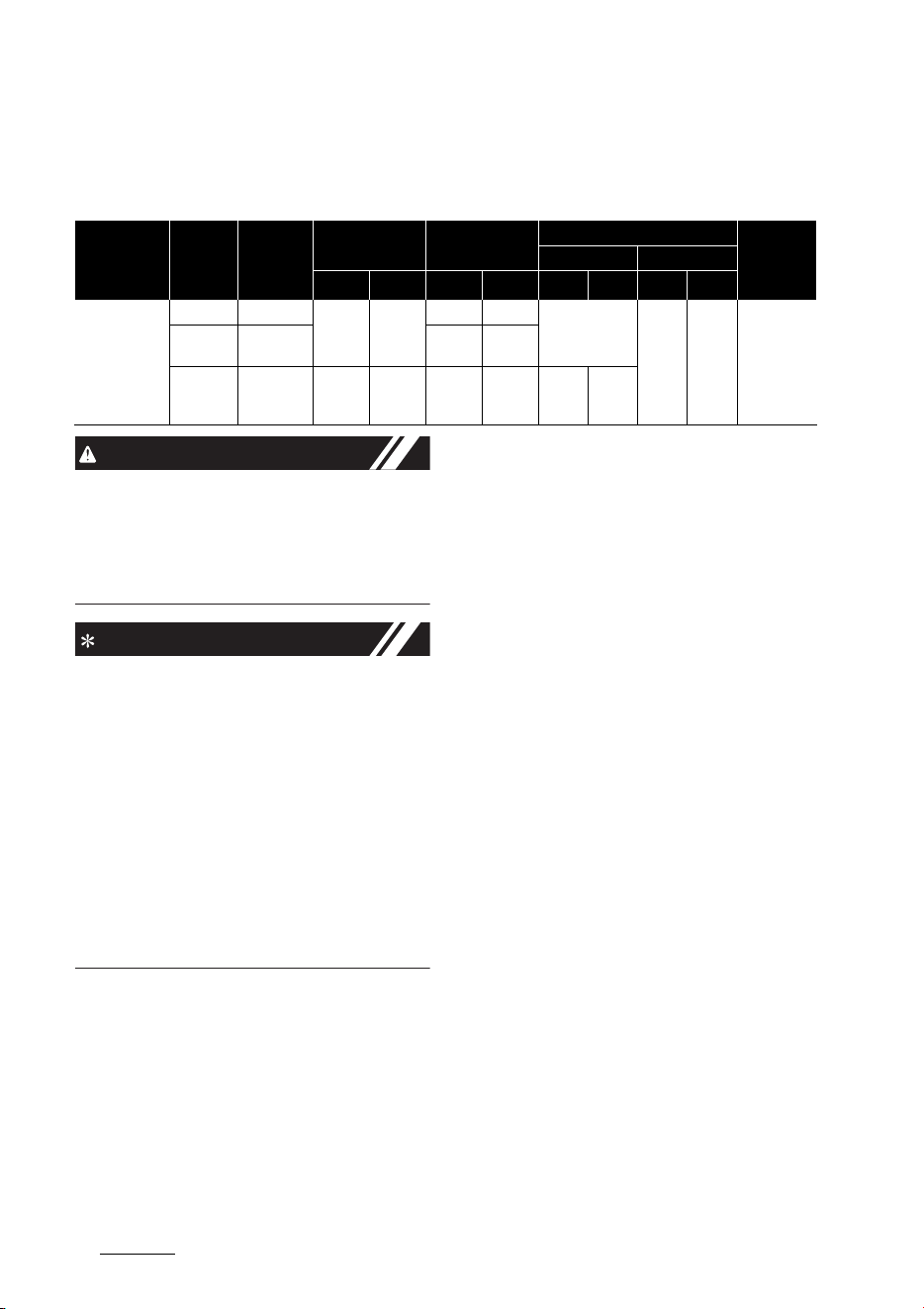
Specifications & Consumer information
69
Tires and wheels
Tires and wheels
*1. Load Index
*2. Speed Symbol
CAUTION
When replacing tires, use the same size
originally supplied with the vehicle.
Using tires of a different size can dam
-
age the related parts or make it work
irregularly.
NOTICE
僅 We recommend that when replacing
tires, use the same originally supplied
with the vehicles. If not, that affects
driving performance.
僅 When driving in high altitude grades,
it is natural for the atmospheric pres
-
sure to decrease. Therefore, please
check the tire pressure and add more
air when necessary.
- Additionally required tire air pres
-
sure per km above sea level: 1.5 psi/
km
Item Tire size Wheel size
Load capacity Speed capacity
Inflation pressure [bar (psi, kPa)]
Wheel lug
nut torque
kgf·m (lbf·ft,
N·m)
Normal load Maximum load
LI
*1
kg
SS
*2
km/h Front Rear Front Rear
Full size tire
235/55R19 7.5J X 19"
105 925
V 240
2.5 (36, 250)
2.6 (38,
260)
2.9 (42,
290)
11~13
(79~94,
107~127)
255/
45R20
8.0J X 20" H 210
255/40R
21
8.5J X 21" 102 850 Y 300
2.35
(34,
235)
2.7 (39,
270)
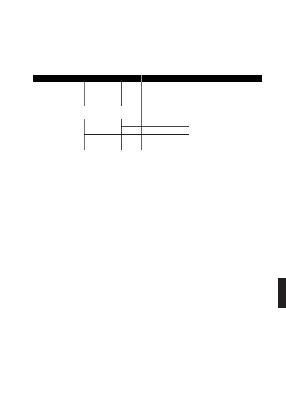
7
9
9
Specifications & Consumer information Recommended lubricants and capacities
Recommended lubricants and capacities
To help achieve proper vehicle performance and durability, use only lubricants of the proper quality.
These lubricants and fluids are recommended for use in your vehicle.
To maintain your vehicle’s best performance, use Kia genuine oil or those of an equivalent standard oil.
Lubricant Volume (L) Classification
Reduction gear fluid
2WD Rear Approx. 3.4~3.5
SK ATF SP4M-1, MICHANG ATF SP4M-1,
S-OIL ATF SP4M-1, Kia Genuine ATF
SP4M-1
4WD
Front Approx. 3.2~3.3
Rear Approx. 3.4~3.5
Brake fluid As required
SAE J1704 DOT-4 LV, FMVSS 116 DOT-4,
ISO4925 CLASS-6
Coolant
Standard type
2WD Approx. 17.7
Mixture of antifreeze and water (Eth
-
ylene-glycol with phosphate-based cool
-
ant for cooling device)
4WD Approx. 17.9
Extended type
2WD Approx. 19.4
4WD Approx. 19.6
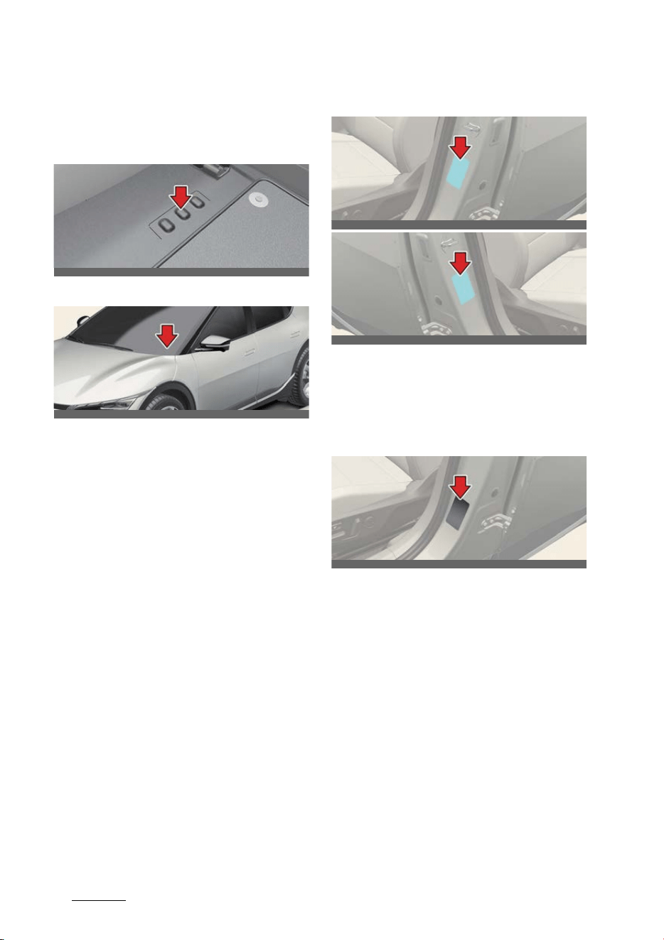
Specifications & Consumer information
89
Vehicle Identification Number (VIN)
Vehicle Identification Number
(VIN)
Type A
Type B
The Vehicle Identification Number (VIN)
is the number used in registering your
vehicle and in all legal matters pertain
-
ing to its ownership, etc.
僅 Type A: Engraved on the floor under
the front left or right seat. Open the
cover to check the VIN.
僅 Type B: Written on a plate attached to
the top left or top right of the dash
-
board through the front windshield.
Vehicle certification label
The vehicle certification label attached
on the center pillar as shown gives the
vehicle identification number (VIN).
Tire specification and pressure
label
The tire label located on the center pillar
as shown gives the tire pressures recom
-
mended for your vehicle. The tires sup
-
plied on your new vehicle are chosen to
provide the best performance for normal
driving.
OCV081001L
OCV081002L
OCV081003L
OCV081003R
OCV081011L
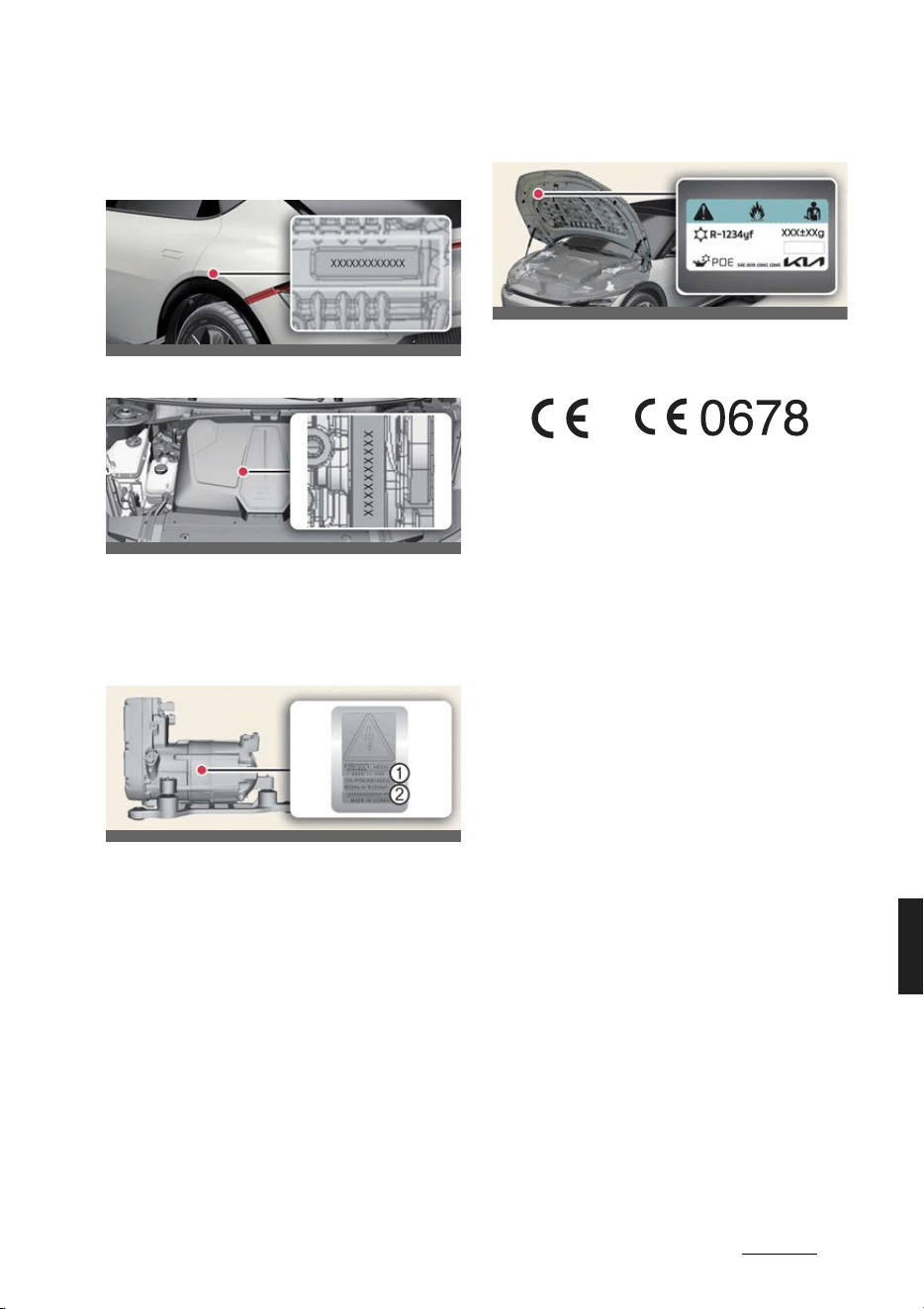
9
9
9
Specifications & Consumer information Motor number
Motor number
2WD
4WD (if equipped)
The motor number is stamped on the
motor as shown.
Air conditioner compressor
label
1
Refrigerant
2
Refrigerant oil
A compressor label informs you the type
of compressor your vehicle is equipped
with such as model, supplier part num
-
ber, production number, refrigerant (1)
and refrigerant oil (2).
Refrigerant label
The refrigerant label is located as shown.
Declaration of conformity
The radio frequency components of the
vehicle comply with requirements and
other relevant provisions of Directive
1995/5/EC.
Further information including the manu
-
facturer's declaration of conformity is
available on Kia website as follows:
http://www.kia-hotline.com
OCV081004L
OCV081005L
OCV081006L
OCV081007
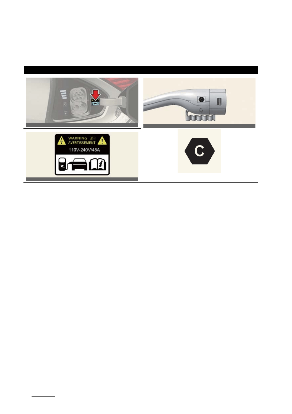
Specifications & Consumer information
109
How to check the symbol on the charging label (For Europe)
How to check the symbol on the charging label (For Europe) (if
equipped)
Precautions for charging AC and
Trickle charger (Portable
charging cable) (AC charging)
1. After opening the charging door,
check the charging symbol at the bot
-
tom of the warning label.
2. Check the charging connector symbol
of the AC and Trickle charger cable.
3. After checking the alphabet letter of
the charging symbol, proceed the
charging step.
* Refer to "Electric charging label sym
-
bol table (For Europe)" on page 9-11.
4. Risk of failure, fire, injury, etc.
expected when using the charging
connector with unmatched symbol.
Precautions for DC charging (DC
charging)
1. After opening the charging door,
check the charging symbol at the bot
-
tom of the warning label.
2. Check the charging connector symbol
at the high speed charging station.
3. After checking the alphabet letter of
the charging symbol, proceed the
charging step.
* Refer to "Electric charging label sym
-
bol table (For Europe)" on page 9-11.
4. Risk of failure, fire, injury, etc.
expected when using the charging
connector with unmatched symbol.
Vehicle charging INLET Charging connector OUTLET
<Symbol location and application example>
OCVQ011015L
OCVQ011016L
OCV081009L
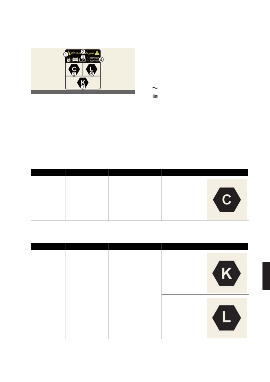
11
9
9
Specifications & Consumer information How to check the symbol on the charging label (For Europe)
Electric charging label (For Europe)
The electric charging label is attached
on the charging door.
1. Warning for high voltage
2. Symbol for charging door
3. For further details, refer to "How to
check the symbol on the charging
label (For Europe) (if equipped)" on
page 9-10.
4. Charging voltage and current
( ): AC Single phase
( ): AC 3 phase
5~7: Symbols for charging type. For fur
-
ther details, refer to "Electric charging
label symbol table (For Europe)" on page
9-11.
Electric charging label symbol table (For Europe)
AC and Trickle charger charging
DC charging
OCV081012L
Supply Type Configuration Type of Accessory Voltage range Identifier
AC 7P
Vehicle connector and vehicle
inlet
≤480V RMS
Supply Type Configuration Type of Accessory Voltage range Identifier
DC 7P COMBO
Vehicle connector and vehicle
inlet
50V to 500V
200V to 920V


AAbbreviation
Abbreviation

Abbreviation
2A
Abbreviation
ABS
Anti-lock Brake System
BAS
Brake Assistant System
BCA
Blind-Spot Collision-Avoidance Assist
BCW
Blind-Spot Collision Warning
BVM
Blind-Spot View Monitor
CC
Cruise Control
CRS
Child Restraint System
DAW
Driver Attention Warning
DRL
Daytime Running Light
EBD
Electronic Brake force Distribution
ECM
Electric Chromic Mirror
EPS
Electric Power Steering
ESC
Electronic Stability Control
ESS
Emergency Stop Signal
FCA
Forward Collision-Avoidance Assist
HAC
Hill-start Assist Control
HBA
High Beam Assist
HDA
Highway Driving Assist
HMSL
High Mounted Stop Lamp
HUD
Head-Up Display
ISLA
Intelligent Speed Limit Assist
LATCH
Lower Anchors and Tether for Chil
-
dren
LFA
Lane Following Assist
LKA
Lane Keeping Assist
MCB
Multi-Collision Brake
MDPS
Motor Driven Power Steering
MIL
Malfunction Indicator Lamp
MSLA
Manual Speed Limit Assist

3A
Abbreviation
NSCC
Navigation-based Smart Cruise Con
-
trol
PCA
Reverse Parking Collision-Avoidance
Assist
PDW
Reverse Parking Distance Warning
RCCA
Rear Cross-Traffic Collision-Avoid
-
ance Assist
RCCW
Rear Cross-Traffic Collision Warning
RVM
Rear View Monitor
SBW
Shift-By-Wire
SCC
Smart Cruise Control
SEA
Safe Exit Assist
SEW
Safe Exit Warning
SRS
Supplemental Restraint System
SRSCM
SRS Control Module
SVM
Surround View Monitor
TBT
Turn By Turn
TCS
Traction Control System
TIN
Tire Identification Number
TPMS
Tire Pressure Monitoring System
VIN
Vehicle Identification Number
VSM
Vehicle Stability Management


BAppendix
Appendix
Akstur að vetri til ........................................................................... 2-2

Appendix
2A
Akstur að vetri til
Appendix
Akstur að vetri til
Alvarlegar veðuraðstæður að vetri til
leiða til meira slits og annarra van
-
dam쌴la.
Til að l쌴gmarka vandam쌴l 썿 akstri að
vetri til ættir þ쏒 að fylgja eftirfarandi
upp쌴stungum:
Aðstæður 썿 snj쎣 eða h쌴lku
Til að geta ekið 쎨kutækinu þ썿nu 썿 dj쏒pum
snj쎣 kann að vera nauðsynlegt að nota
snj쎣hj쎣lbarða eða setja snj쎣keðjur 쌴
hj쎣lin.
Ef þ쎨rf er 쌴 snj쎣hj쎣lb쎨rðum er nauðsyn
-
legt að velja hj쎣lbarða sem eru jafngildir
upprunalegu hj쎣lb쎨rðunum að stærð og
tegund. Misbrestur 쌴 að gera svo kann
að hafa 쎣hagstæð 쌴hrif 쌴 쎨ryggi og aks
-
turseiginleika 쎨kutækisins þ썿ns. Ennfre
-
mur kunna hraðakstur, sn쎨gg hr쎨ðun,
skyndileg beiting hemla og krappar
beygjur hugsanlega að reynast mj쎨g
hættuleg iðja.
Meðan 쌴 hraðaminnkun stendur skal
nota hemla 쎨kutækisins til hins 쏯trasta.
Skyndileg beiting hemla 쌴 snævi þ쎨ktum
eða 썿suðum vegum kann að valda þv썿 að
b썿llinn renni til. Þ쏒 þarft að halda nægi
-
legri fjarlægð 쌴 milli 쎨kutækisins þ썿ns og
쎨kutækisins fyrir framan þig. Beittu ein
-
nig hemlunum varlega. Athugaðu að
uppsetning snj쎣keðja 쌴 hj쎣lbarðana mun
veita meiri aksturskraft en kemur ekki 썿
veg fyrir hliðarskrik.
Sumarhj쎣lbarðar (if equipped)
僅 Sumarhj쎣lbarðar eru notaðir til að
h쌴marka akstursframmist쎨ðu 쌴 þur
-
rum vegum.
僅 Ef hitastigið er undir 7°C eða þ쏒 ekur
쌴 snævi þ쎨ktum eða 썿suðum vegum
glata sumarhj쎣lbarðarnir hemlunar
-
frammist쎨ðu sinni og dragkrafti þar
sem grip hj쎣lbarðanna minnkar
umtalsvert.
僅 Ef hitastigið er undir 7°C eða þ쏒 ekur
쌴 snævi þ쎨ktum eða 썿suðum vegum
skaltu setja undir snj쎣hj쎣lbarða eða
heils쌴rshj쎣lbarða af s쎨mu stærð og
staðlaða hj쎣lbarða 쎨kutækisins þ썿ns
svo akstur verði 쎨ruggari. Bæði snj쎣h
-
j쎣lbarðar og heils쌴rshj쎣lbarðar eru
með M+S-merkingar.
僅 Þegar M+S-hj쎣lbarðar eru notaðir skal
nota hj쎣lbarða með sama mynstri og
framleidda af sama framleiðanda svo
akstur verði 쎨ruggari.
僅 Þegar ekið er með M+S-hj쎣lbarða með
lægri leyfilegan h쌴markshraða en fyrir
staðlaða sumarhj쎣lbarða 쎨kutækis
-
ins, skal gæta þess að fara ekki
umfram hraðann sem leyfður er fyrir
M+S-hj쎣lbarðana.
Snj쎣hj쎣lbarðar
Ef þ쏒 setur snj쎣hj쎣lbarða undir 쎨kutækið
þitt skaltu ganga 쏒r skugga um að þeir
s썗u þverbandahj쎣lbarðar af s쎨mu stærð
og 쌴 sama 쌴lagssviði og upprunalegu
hj쎣lbarðarnir. Settu snj쎣hj쎣lbarða 쌴 쎨ll
fj쎨gur hj쎣lin til að jafna 쏒t meðh쎨ndlun
쎨kutækisins við 쎨ll veðurskilyrði. Hafðu 썿
huga að gripið sem snj쎣hj쎣lbarðar veita
쌴 þurrum vegum kann að vera minna en
grip hj쎣lbarðanna sem upphaflega voru
settir upp 쌴 쎨kutækinu. Þ쏒 ættir að aka
varlega, jafnvel þegar vegurinn er auður.
Athugaðu hj쌴 hj쎣lbarðasalanum
varðandi r쌴ðleggingar um h쌴mark
-
shraða.
Settu ekki upp neglda hj쎣lbarða 쌴n þess
að athuga fyrst allar viðeigandi
reglugerðir varðandi m쎨gulega takmar
-
kanir 쌴 notkun þeirra.
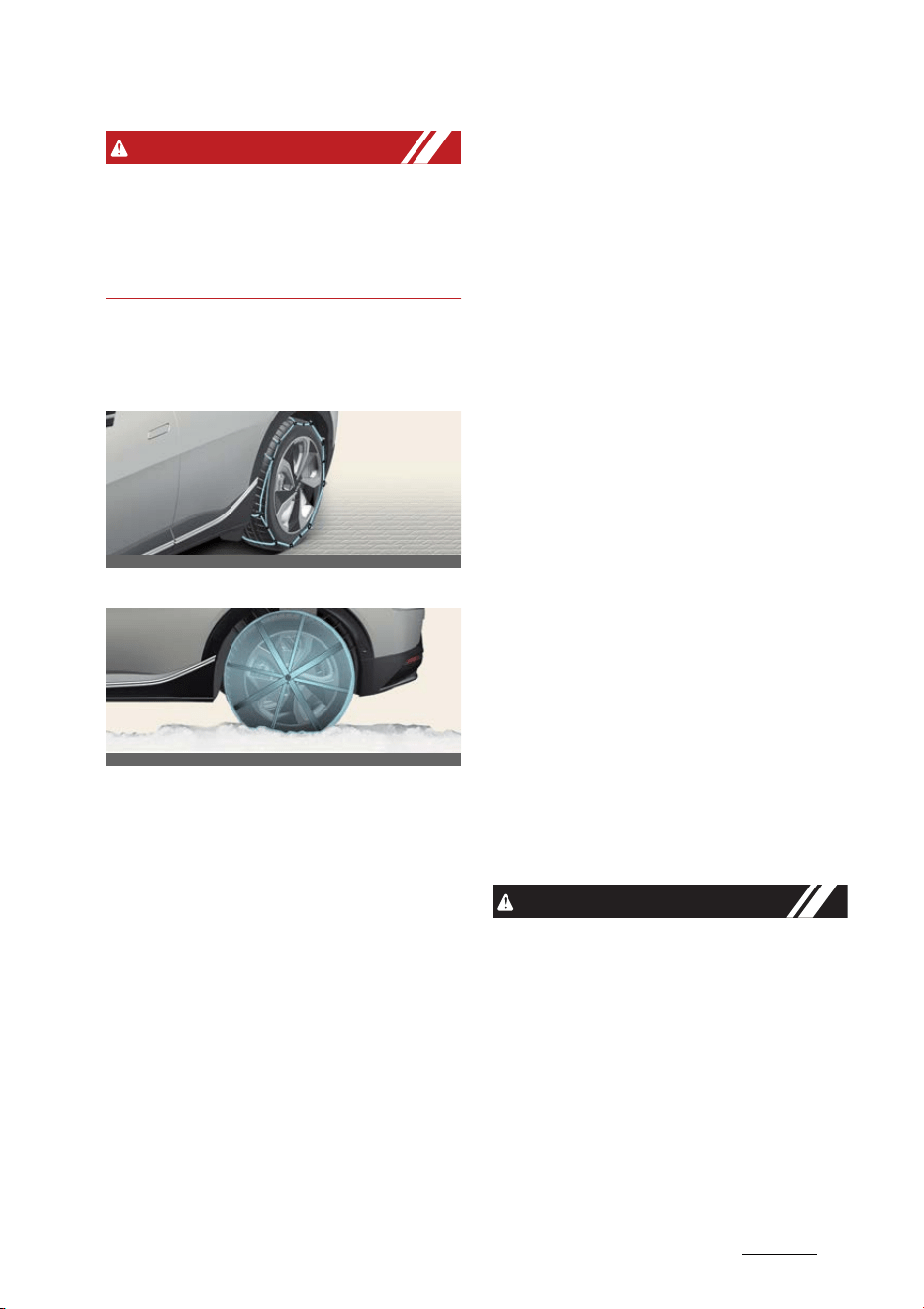
3A
Appendix Akstur að vetri til
WARNING
Snj쎣hj쎣lbarðar ættu að vera af jafngildri
stærð og tegund og venjulegir hj쎣l
-
barðar 쎨kutækisins. Að 쎨ðrum kosti
kann það að hafa 쎣hagstæð 쌴hrif 쌴 aks
-
tureiginleika 쎨kutækisins.
Keðjur 쌴 hj쎣lbarða
Keðjur 쏒r v썿r
Keðjur 쏒r d쏒k
Vegna þess að hliðar þverbandahj쎣l
-
barða eru þynnri kunna þeir að skem
-
mast ef sumar tegundir af snj쎣keðjum
eru festar við þ쌴. Þar af leiðandi er mælt
með notkun snj쎣hj쎣lbarða 썿 stað
snj쎣keðja. Ekki skal setja keðjur 쌴
쎨kutæki sem b쏒in eru 쌴lfelgum;
snj쎣keðjur kunna að valda skemmdum 쌴
felgunum.
Skemmdir 쌴 쎨kutækinu þ썿nu af v쎨ldum
rangrar notkunar snj쎣keðja falla ekki
undir 쌴byrgð framleiðandans.
Þegar þ쏒 notar snj쎣keðjur skaltu festa
þær við drifhj쎣lin sem h썗r segir.
僅 숼 afturhj쎣ladrifnum 쎨kutækjum eru
það afturhj쎣lin sem gefa aflið. Þv썿
verður að setja snj쎣keðjur 쌴 hj쎣l
-
barðana að aftan.
僅 숼 쎨kutækjum með aldrifi m쌴 aðeins
setja snj쎣keðjur 쌴 hj쎣lbarða að aftan.
Við þær aðstæður skal l쌴gmarka aks
-
tursvegalengd til að koma 썿 veg fyrir
skemmdir 쌴 aldrifskerfinu.
僅 Þegar keðjur hafa verið settar 쌴 skal
aka hægt. Ef þ쏒 heyrir hlj쎣ð sem
verður vegna þess að keðjurnar
snerta yfirbygginguna skaltu hægja 쌴
þar til hlj쎣ðið hættir og fjarlægja keð
-
juna um leið og þ쏒 ferð að aka 쌴
hreinsuðum vegum til að koma 썿 veg
fyrir skemmdir.
僅 Keðjur af rangri stærð eða rangt settar
upp kunna að skemma hemlaleiðslur
쎨kutækisins, fj쎨ðrun, yfirbyggingu og
hj쎣l. Þar af leiðandi skaltu fylgja
leiðbeiningum framleiðandans þegar
þ쏒 setur 쌴 snj쎣keðjur og festa þær
eins þ썗tt og m쎨gulegt er. Aktu hægt,
innan við 30 km/klst. (20 m/klst), með
uppsettar keðjur.
僅 Settu upp keðjur 쌴 hj쎣lbarðana sem
standast tæknil쏯singu hverrar hj쎣l
-
barðastærðar til að koma 썿 veg fyrir
skemmdir 쌴 쎨kutækinu.
- Bæði 19 og 20 tommu hj쎣lbarðar
nota snj쎣keðjur 쏒r d쏒k.
CAUTION
僅 Gakktu 쏒r skugga um að snj쎣keðjur
-
nar s썗u af r썗ttri stærð og tegund fyrir
hj쎣lbarðana þ썿na. Rangar snj쎣keðjur
geta valdið skemmdum 쌴 yfirbyg
-
gingu 쎨kutækisins og fj쎨ðrun og ekki
er v썿st að þær falli undir 쌴byrgð fram
-
leiðanda 쎨kutækisins. Einnig geta
tengikr쎣kar snj쎣keðjanna skemmst
vegna snertingar við 쎨kutækið sem
veldur þv썿 að snj쎣keðjurnar losna fr쌴
hj쎣lbarðanum. Gakktu 쏒r skugga um
OCV051102L
OCV051103L

Appendix
4A
Akstur að vetri til
að snj쎣keðjurnar s썗u 썿 SAE-flokki og
씮S“-vottaðar.
僅 Athugaðu alltaf uppsetningu og r썗tta
festingu keðja eftir að hafa ekið um
það bil 0,5 til 1 km (0,3 til 0,6 m썿lur) til
að tryggja 쎨rugga festingu. Hertu
keðjurnar eða settu þær upp aftur ef
þær eru lausar.

IIndex
Index

2I
Index
A
AC charge 2-24
checking charging status
2-24
how to connect
2-24
how to disconnect
2-25
active air flap 6-42
malfunction
6-42
adjusting rear seatback angle 4-8
air bag 4-29
adding equipment to or modifying
your air bag-equipped vehicle
4-46
additional safety precautions
4-45
air bag collision sensors
4-41
air bag inflation conditions
4-42
air bag non-inflation conditions
4-43
air bag warning labels
4-46
curtain air bag
4-39
driver’s and passenger’s front
air bags
4-36
side air bag and front center air bag
4-38
SRS care
4-45
SRS components and functions
4-34
warning and indicator light
4-32
air bag collision sensors 4-41
air bag warning and indicator light
air bag warning light 4-32
air bag warning labels 4-46
all wheel drive (4WD) 6-39
emergency precautions
6-41
for safe 4WD operation
6-39
ambient lights 5-88
anti-lock brake system (ABS) 6-29
appearance care 8-40
exterior care
8-40
interior care
8-44
armrest 4-12
adjusting the armrest
4-12
carrying long/narrow cargo
4-12
audio system 5-95
sharkfin antenna
5-95
USB port
5-95
augmented reality HUD 5-58
head-up display information
5-58
head-up display settings
5-58
precautions
5-59
auto. controls that use climate
control settings
5-84
auto defogging 5-82
AUTO HOLD 6-28
automatic climate control
system
5-75
adjusting the driver and passenger side
temperature to the same value
5-80
changing temperature scale
5-80
controlling automatically
5-80
controlling fan speed
5-81
controlling the temperature
5-80
operating
5-77
using the infotainment/climate
switchable controller
5-76
B
battery 8-13
battery capacity label
8-14
battery recharging
8-14
for best battery service
8-13
reset items
8-15
battery saver function 5-60
before driving 6-6
good braking practices
6-7
good driving practices
6-6
necessary vehicle inspections
6-6
blind-spot collision-avoidance
assist (BCA) 6-67
malfunction and limitations
6-73
operation
6-70
settings
6-69
blind-spot view monitor
(BVM)
6-100
malfunction
6-100
operation
6-100
settings
6-100
brake assist system (BAS) 6-32
brake disc cleaning 6-22
brake fluid 8-9
checking the brake fluid level
8-9
brake system 6-22
AUTO HOLD
6-28
brake disc cleaning
6-22
in the event of brake failure
6-22

3I
parking brake 6-24
C
cargo security screen 5-86
carrying long/narrow cargo 4-12
center console storage/glove
box
5-85
charge indicator lamp for electric
vehicle
2-19
charging status
2-19
charge types for electric vehicle 2-17
charging information
2-17
charging time information
2-17
charging types
2-18
charging and climate 2-8
off-peak time settings
2-9
target temperature settings
2-9
charging connector lock 2-19
locking charging cable
2-19
charging door 5-34
opening/closing the charging door
5-34
charging electric vehicle 2-21
electric charging door
2-21
charging the electric vehicle
(abrupt stop)
2-35
child restraint system (CRS) 4-21
children always in the rear
4-21
installing a CRS
4-23
selecting a CRS
4-22
child-protector rear door lock 5-16
climate control air filter 8-11
replacing the climate control air filter
8-11
climate control system 5-72
coolant 8-9
cruise control (CC) 6-101
operation
6-101
cup holders 5-88
curtain air bag 4-39
D
day/night rearview mirror 5-42
daytime running light (DRL) 5-61
DC charge 2-26
checking charging status
2-26
how to connect
2-26
how to disconnect
2-27
declaration of conformity 6-187
door locks 5-11
automatic door lock and unlock
features
5-15
deadlocks
5-15
inside the vehicle
5-13
manual door lock switch
5-15
outside the vehicle
5-11
rear door locks
5-16
rear occupant alert (ROA)
5-17
drift mode 6-37
drive mode 6-35
drive mode integrated control
system
6-35
drive mode
6-35
drive mode characteristics for 4WD
6-36
driver attention warning
(DAW) 6-94
malfunction and limitations
6-98
operation
6-96
settings
6-95
driver position memory system 5-19
easy access function
5-20
recalling memory position
5-19
resetting
5-20
setting memory position
5-19
driver’s and passenger’s front air
bags 4-36
driver’s side fuse panel 8-26
driving electric vehicle 2-36
distance to empty
2-37
ECO driving
2-38
energy consumption
2-38
LCD display messages
2-41
power/charge gauge
2-39
starting the vehicle
2-36
state of charge (SOC) gauge
2-39
stopping the vehicle
2-36
virtual engine sound system (VESS)
2-36
warning and indicator lights (related to
electric vehicle)
2-40

4I
E
electric chromic mirror (ECM) 5-42
electronic limited slip
differential
6-33, 6-34
electronic stability control
(ESC) 6-29
emergency commodity 7-17
emergency starting 7-4
jump-starting (12V battery)
7-4
push-starting
7-5
emergency stop signal (ESS) 6-32
emergency while driving 7-3
flat tire while driving
7-3
vehicle stalls at a crossroad or
crossing
7-3
vehicle stalls while driving
7-3
ev menu 2-6
charging and climate
2-8
ev mode screen
2-7
ev settings
2-14
nearby stations
2-13
next departure
2-8
vehicle to load (V2L)
2-9
ev settings 2-14
battery conditioning mode
2-15
charging current
2-14
charging limit
2-14
utility mode
2-15
F
floor mat anchors 5-94
forward collision-avoidance assist
(FCA)
6-43
malfunction and limitations
6-55
operation
6-48
settings
6-46
forward/reverse parking distance
warning (PDW) 6-154
malfunction and precautions
6-157
operation
6-155
settings
6-154
front trunk 5-33
closing the front trunk
5-33
opening the front trunk
5-33
fuses 8-22
replacing inner panel fuse
8-23
replacing motor room fuse
8-24
G
glove box lamp 5-72
H
headlamp aiming (for europe) 8-35
headlamp escort function 5-60, 5-70
headlamp leveling adjustment 5-67
headrest 4-10
adjusting the headrest
4-10
removing/reinstalling the headrest
4-11
heated steering wheel 5-39
high beam assist (HBA) 5-63
highway driving assist (HDA) 6-126
malfunction and limitations
6-134
operation
6-128
settings
6-127
hill-start assist control (HAC) 6-30
hood 5-32
opening/closing the hood
5-32
I
immobilizer system 5-8
infotainment system 5-94
audio system
5-95
using the infotainment/climate
switchable controller
5-94
instrument cluster 5-45
intelligent front-lighting system
(IFS) 5-65
intelligent speed limit assist (ISLA)
malfunction and limitations 6-92
operation
6-90
settings
6-89
interior features 5-88
ambient lights
5-88
cup holders
5-88
floor mat anchors
5-94
power outlet
5-91
seat warmer/ventilation
5-88
sun visor
5-90
USB charger
5-90

5I
wireless smartphone charging
system
5-92
interior lights 5-71
automatic turn-off function
5-71
glove box lamp
5-72
luggage space lamp
5-71
map lamp
5-71
room lamp
5-71
vanity mirror lamp
5-71
interior rearview mirror 5-42
day/night rearview mirror
5-42
electric chromic mirror (ECM)
5-42
i-pedal 6-16
ISOFIX anchorage system for
children
4-24
recommended CRS for vehicle
4-28
securing a CRS with a lap/shoulder
belt
4-25
securing a CRS with the "ISOFIX
anchorage system"
4-24
securing a CRS with the "top-tether
anchorage system"
4-25
suitability of each seating position for
belted & ISOFIX CRS
4-27
K
keys 5-6
locking/unlocking/remote starting/
remote parking with the smart key
5-6
removing the mechanical key from the
smart key
5-7
replacing the key battery
5-7
L
lamps 8-33
bulb replacement precautions
8-33
headlamp aiming (for europe)
8-35
light position (front)
8-34
light position (rear)
8-35
light position (side)
8-35
lane following assist (LFA) 6-123
malfunction and limitations
6-126
operation
6-124
settings
6-123
lane keeping assist (LKA) 6-62
malfunction and limitations
6-65
operation
6-64
settings
6-62
LCD display 5-47
changing LCD display modes
5-47
LCD display messages
5-51
LCD display modes
5-47
LCD display modes
driver assistance settings (infotainment
system)
5-50
driving assist mode
5-48
electric energy economy
5-48
information mode
5-49
master warning mode
5-49
service Interval
5-49
trip computer mode
5-48
turn by turn (TBT) mode
5-49
lighting 5-60
battery saver function
5-60
daytime running light (DRL)
5-61
headlamp escort function
5-60
headlamp leveling adjustment
5-67
high beam assist (HBA)
5-63
intelligent front-lighting system (IFS)
5-65
lighting controls
5-61
traffic change (for europe)
5-61
luggage net holder 5-86
luggage space lamp 5-71
luggage tray 5-86
lumbar support 4-5
M
main components of electric
vehicle
2-4
high voltage battery warmer system
2-5
high voltage (HV) battery
2-4
maintenance services 8-4
owner maintenance precautions
8-4
owner’s responsibility
8-4
manual speed limit assist
(MSLA) 6-86
operation
6-86
map lamp 5-71
maximum power output mode 6-38
mirrors 5-42
interior rearview mirror
5-42
outside rear view mirror
5-42

6I
motor compartment fuse panel 8-29
motor room compartment 8-3
multi-collision brake (MCB) 6-31
N
navigation-based smart cruise
control (NSCC)
6-118
limitations
6-120
operation
6-119
settings
6-118
O
one pedal driving 6-15
outside rear view mirror 5-42
adjusting
5-42
auto reverse function
5-43
folding
5-42
owner maintenance schedule 8-5
P
Pan-European eCall system 7-18
pan-european ecall system
description of the ecall in-vehicle
system
7-18
information on data processing
7-19
parking brake 6-24
electronic parking brake (EPB)
6-24
passenger’s front air bag ON/OFF
switch 4-33
portable charge 2-28
charging status indicator lamp for
portable charger
2-32
checking charging status
2-31
how to connect
2-30
how to disconnect
2-34
precautions
2-34
setting the charge level
2-28
power button 6-8
power outlet 5-91
power tailgate 5-21
adjusting power tailgate opening
height
5-24
adjusting power tailgate speed
5-24
power tailgate automatic reversal
5-22
resetting
5-24
setting power tailgate
5-24
precautions for charging electric
vehicle 2-22
unlock charging connector
in emergency
2-22
R
rear cross-traffic collision-
avoidance assist (RCCA)
6-142
malfunction and limitations
6-147
operation
6-144
settings
6-143
rear door locks 5-16
child-protector rear door lock
5-16
electronic child safety lock system
5-16
rear occupant alert (ROA) 5-17
rear view monitor (RVM) 6-136
malfunction and limitations
6-137
operation
6-136
settings
6-136
reduction gear 6-10
changing gear
6-10
LCD display messages
6-13
shift-lock system
6-11
regenerative braking system 6-15
adjusting with paddle shifter
6-15
i-pedal
6-16
relaxion comfort seat 4-5
remote smart parking assist
(RSPA) 6-166
malfunction and limitations
6-183
operation
6-169
settings
6-168
reverse parking collision-
avoidance assist (PCA) 6-159
malfunction and limitations
6-162
operation
6-161
settings
6-159
reverse parking distance warning
(PDW)
6-150
malfunction and precautions
6-152
operation
6-151
settings
6-151
review of electric vehicle 2-3
road warning 7-3

7I
hazard warning flasher 7-3
room lamp 5-71
S
safe exit assist (SEA) 6-81
malfunction and limitations
6-84
operation
6-83
settings
6-82
safe exit warning (SEW) 6-77
malfunction and limitations
6-79
operation
6-78
settings
6-78
safety precautions for electric
vehicle
2-46
scheduled charging 2-20
scheduled maintenance service 8-6
seat 4-3
adjusting the front seat
4-4
adjusting the rear seat
4-8
infotainment system
4-4
seatback pocket
4-6
seat belt pretensioner 4-16
seat belt restraint system 4-14
3-point system with emergency locking
retractor
4-15
seat belt pretensioner
4-16
seat belt warning light
4-14
seat belt warning light 4-14
seat belts 4-13
care of seat belts
4-20
precautions
4-18
seat belt restraint system
4-14
seat warmer/ventilation 5-88
seatback folding 4-8
seatback pocket 4-6
selecting a CRS 4-22
CRS types
4-22
sharkfin antenna 5-95
side air bag and front center
air bag 4-38
smart cruise control (SCC) 6-104
display and control
6-109
malfunction and limitations
6-114
settings
6-105, 6-108
smart regeneration system 6-17
malfunction and limitations
6-18
operating
6-17
smart tailgate 5-25
smart ventilation 5-84
special driving conditions 6-194
specifications
air conditioner compressor label 9-9
air conditioning system
9-4
available front trunk weight
9-4
bulb wattage
9-5
declaration of conformity
9-9
dimensions
9-2
electric vehicle specifications
9-3
gross vehicle weight
9-3
how to check the symbol on the
charging label (for europe)
9-10
luggage volume
9-3
motor number
9-9
recommended lubricants and
capacities
9-7
refrigerant label
9-9
tire specification and pressure label
9-8
tires and wheels
9-6
vehicle certification label
9-8
vehicle identification number (VIN)
9-8
starting the vehicle 6-8
power button
6-8
steering wheel 5-39
adjusting the angle and height
5-39
heated steering wheel
5-39
horn
5-40
storage compartment 5-85
cargo security screen
5-86
center console storage/glove box
5-85
luggage net holder
5-86
luggage tray
5-86
sun visor 5-90
surround view monitor (SVM) 6-138
malfunction and limitations
6-141
operation
6-140
settings
6-139
T
tailgate 5-21
emergency safety release
5-27
opening the smart tailgate
5-25
opening/closing the manual tailgate
5-21
opening/closing the power tailgate
5-21

8I
tailgate emergency safety
release
5-27
theft-alarm system 5-9
armed stage
5-9
disarmed stage
5-10
immobilizer system
5-8
theft-alarm stage
5-9
ultrasonic intrusion protection (UIP)
5-9
tire mobility kit 7-10
checking tire inflation pressure
7-13
components of the tire mobility kit
7-11
distributing the sealant
7-12
safe use of the tire mobility kit
7-14
using the tire mobility kit
7-12
tire pressure monitoring system
(TPMS)
7-6
checking the tire pressure
7-6
malfunction indicator
7-8
when the telltale lights up
7-7
tires and wheels 8-15
checking tire inflation pressure
8-15
low aspect ratio tire
8-21
recommended cold tire inflation
pressures
8-15
tire care
8-15
tire maintenance
8-18
tire replacement
8-17
tire rotation
8-17
tire sidewall labeling
8-19
tire traction
8-18
wheel alignment and tire balance
8-17
wheel replacement
8-18
towing 7-15
emergency towing
7-15
towing service
7-15
traffic change (for europe) 5-61
trailer towing 6-201
driving with a trailer
6-202
hitches
6-202
if you do decide to tow a trailer
6-205
maintenance when towing a trailer
6-205
safety chains
6-202
trailer brakes
6-202
U
ultrasonic intrusion protection
(UIP) 5-9
unlock charging connector in
emergency
2-22
USB charger 5-90
USB port 5-95
using the infotainment/climate
switchable controller
5-94
V
vanity mirror lamp 5-71
vehicle power 6-8
starting the vehicle
6-8
vehicle safety system 6-29
anti-lock brake system (ABS)
6-29
brake assist system (BAS)
6-32
electronic stability control (ESC)
6-29
emergency stop signal (ESS)
6-32
hill-start assist control (HAC)
6-30
multi-collision brake (MCB)
6-31
vehicle stability management (VSM)
6-31
vehicle settings (infotainment
system) 5-53
vehicle stability management
(VSM) 6-31
vehicle to load (V2L) 2-9
energy information
2-10
how to connect
2-10
LCD display messages
2-11
vehicle weight 6-207
base curb weight
6-207
cargo weight
6-207
GAW (gross axle weight)
6-207
GAWR (gross axle weight rating)
6-207
GVW (gross vehicle weight)
6-207
GVWR (gross vehicle weight rating)
6-207
overloading
6-207
vehicle curb weight
6-207
vehicle will not start 7-4
virtual engine sound system
(VESS) 2-36
W
warning and indicator lights 5-54
washer fluid 8-10
checking the washer fluid level
8-10
welcome system 5-70

9I
body silhouette lamp 5-70
headlamp escort function
5-70
interior lighting
5-70
wide sunroof 5-36
automatic reversal
5-37
power sunshade
5-36
resetting the sunroof
5-38
slide open/close
5-37
sunroof open warning
5-39
tilt open/close
5-37
windows 5-28
controlling windows switch
5-30
power windows automatic reversal
5-30
power windows lock button
5-30
remote window closing/opening
5-30
resetting
5-30
windshield defrosting and
defogging
5-82
auto. controls that use climate control
settings
5-84
auto defogging
5-82
defrosting/defogging the windshield
5-82
heat button
5-83
rear window/outside mirror
defroster
5-83
smart ventilation
5-84
winter driving 6-198
wiper blade 8-12
replacing the front wiper blade
8-12
wipers and washers 5-68
washers
5-68
wipers
5-68
wireless smartphone charging
system 5-92