POWER ADAPTER KIT
FOR SMART GARAGE® VIDEO KEYPAD
Product and Accessory
Installation Guide

2
Overview
Before Installing Your Video Keypad
Your Video Keypad must be connected to the myQ app before installing the Power Adapter Kit.
Reference the BLUE user guide provided in your Video Keypad’s packaging for access to those
instructions.
Contents
Contact Us .......................................2
One Year Limited Warranty .......................2
What’s in the Box .................................3
Uninstall Current Mount ..........................4
Choose Wire Route ...............................5
Option 1: External Wire Installation ...............6
Option 2: Through Wire Installation .............10
IMPORTANT
Do you already have an installed Video Keypad?
YES - Skip to page 4.
NO - Skip to page 5.
Additional Resources
Contact Us
For additional information or assistance, please visit: support.chamberlaingroup.com
Or give us a call: +1(800) 528-5880
One Year Limited Warranty
The Chamberlain Group LLC (“Seller”) warrants to the rst consumer purchaser of this product, for the
residence in which this product is originally installed (except where prohibited by applicable law (which may
include the Province of Quebec)), that it is free from defects in materials and/or worksmanship for a period
of 1 year from the date of purchase. The proper operation of this product is dependent on your compliance
with these instructions regarding installation, operation, and maintenance and testing. The warranty does
not cover damage(s) or defects resulting from the failure to comply strictly with these instructions. Because
Seller cannot control the quality of products sold by unauthorized sellers, this limited warranty applies only
to Products that were purchased from Seller or an authorized reseller in the United States or Canada, unless
otherwise prohibited by law. Seller reserves the right to reject warranty claims from purchasers for Products
purchased from unauthorized sellers, including unauthorized internet sites. Please refer to the label on the
battery to properly recycle and dispose of the battery.
For more information, visit www.myq.com/warranty
3
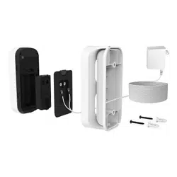
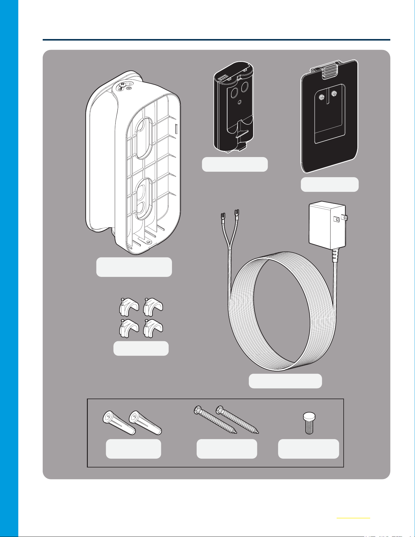
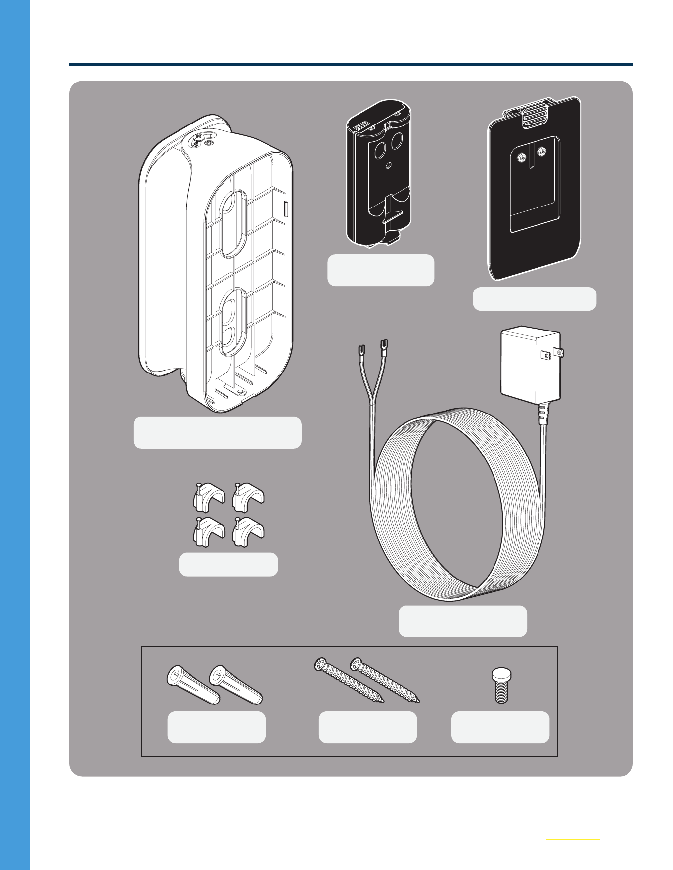
What’s in the Box
Power Module (1)
Back Cover (1)
Security Screw
(1)
Wall Anchors
(1)
25’ Power Cable (1)
1" Mounting
Screws (2)
Power Adapter Kit
Swivel Mount (1)*
Wire Clips (20)
*Must use the included mount to allow for proper wire management.
4
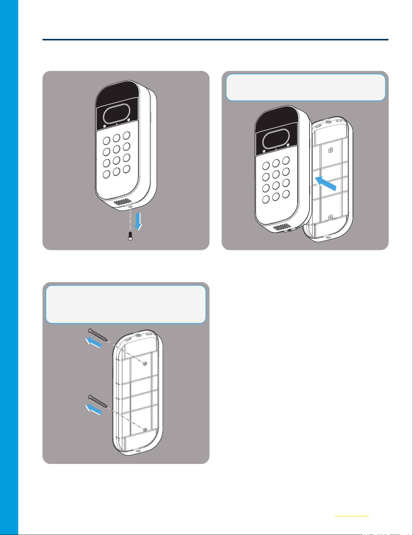
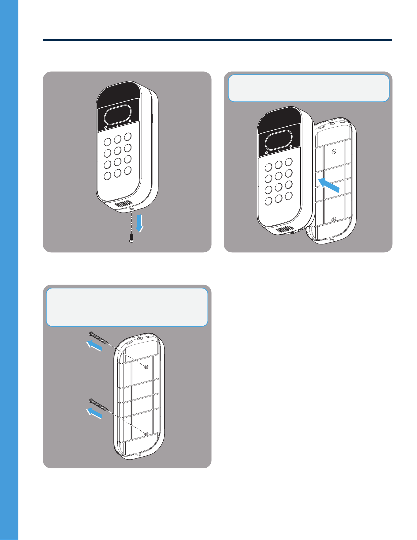
Uninstall Current Mount
01
Remove the security screw from the
VideoKeypad.
02
Take the Keypad o of the existing xed or
swivel mount.
03
Remove the two fastening screws from the
Fixed Mount and remove from the wall.
NOTE: This step applies to both Swivel and Fixed
Mounts.
NOTE: The Fixed Mount DOES NOT WORK with
the Power Adapter Kit. Please use the included
Swivel Mount.
5
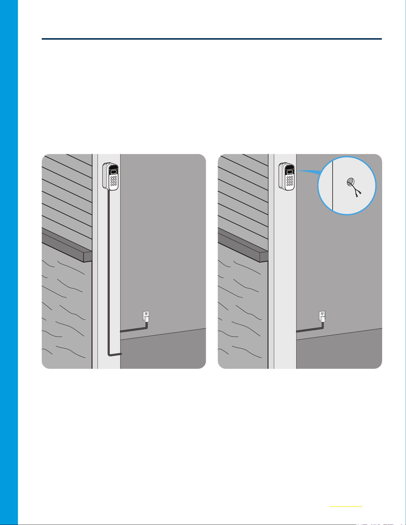
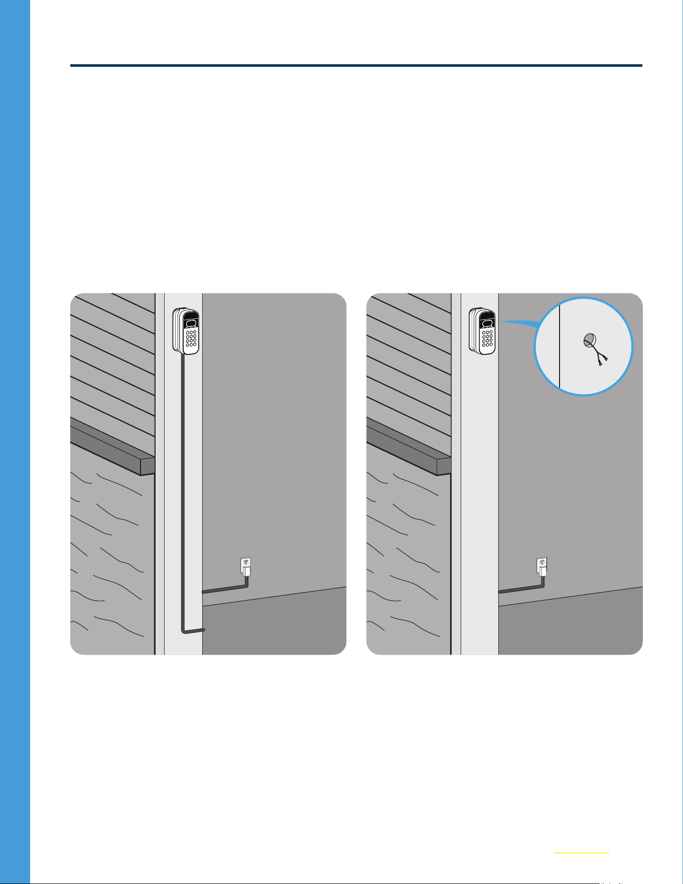
Choose Wire Route
The Power Adapter Kit accommodates for two options to manage the power cord.
• Option 1 - External Wire Installation: Power Cable routes to bottom left or right of mount, then
along your exterior wall, passing through your garage door frame, to an interior outlet. (See p.6).
• Option 2 - Through Wire Installation: Power Cable passes directly through the wall to an
interior outlet for an exterior wireless look. (See p.11).
Decide which option is best for you, ensuring the path to the available outlet is less than 25feet,
then proceed to that step.
Option 1: External Wire Installation Option 2: Through Wire Installation
6
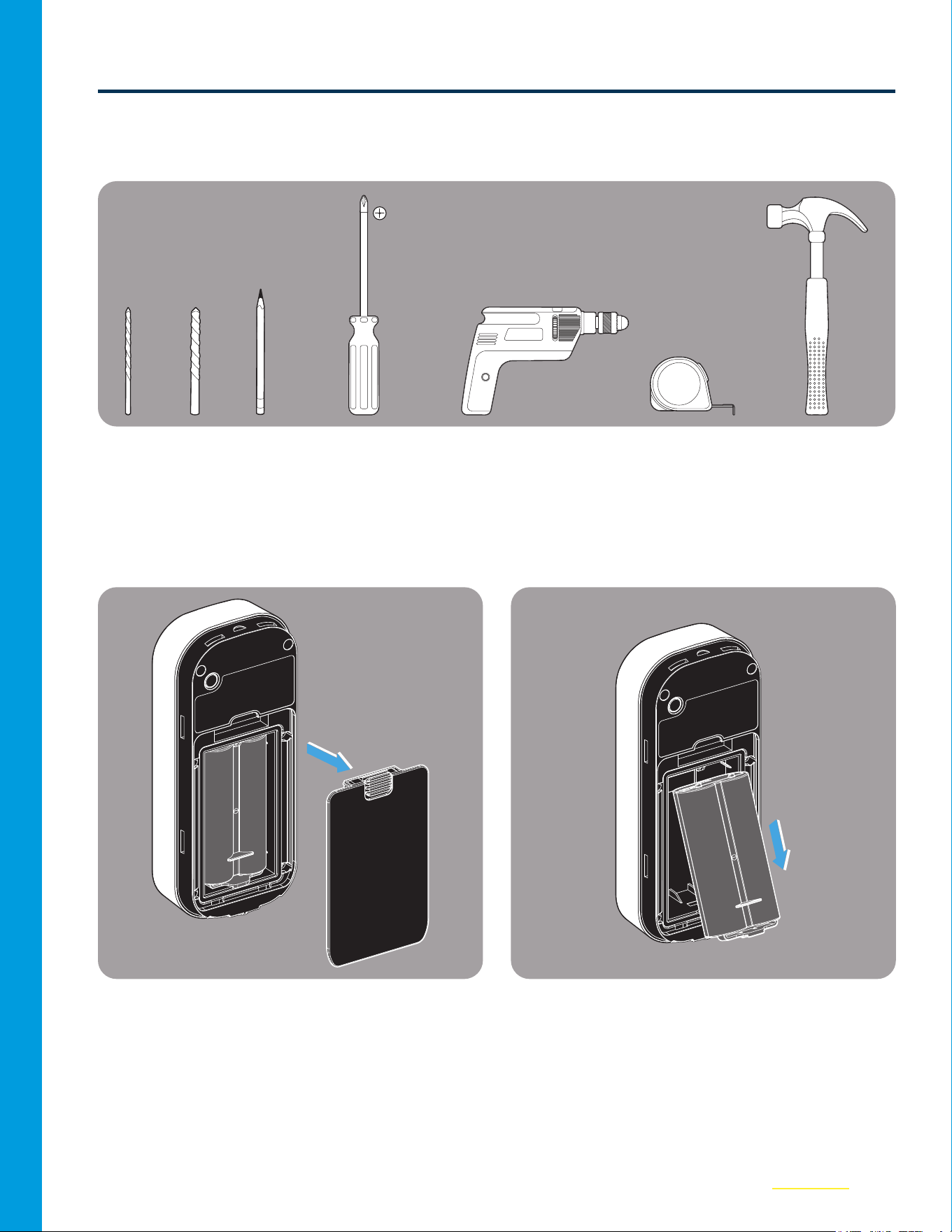
Option 1: External Wire Installation
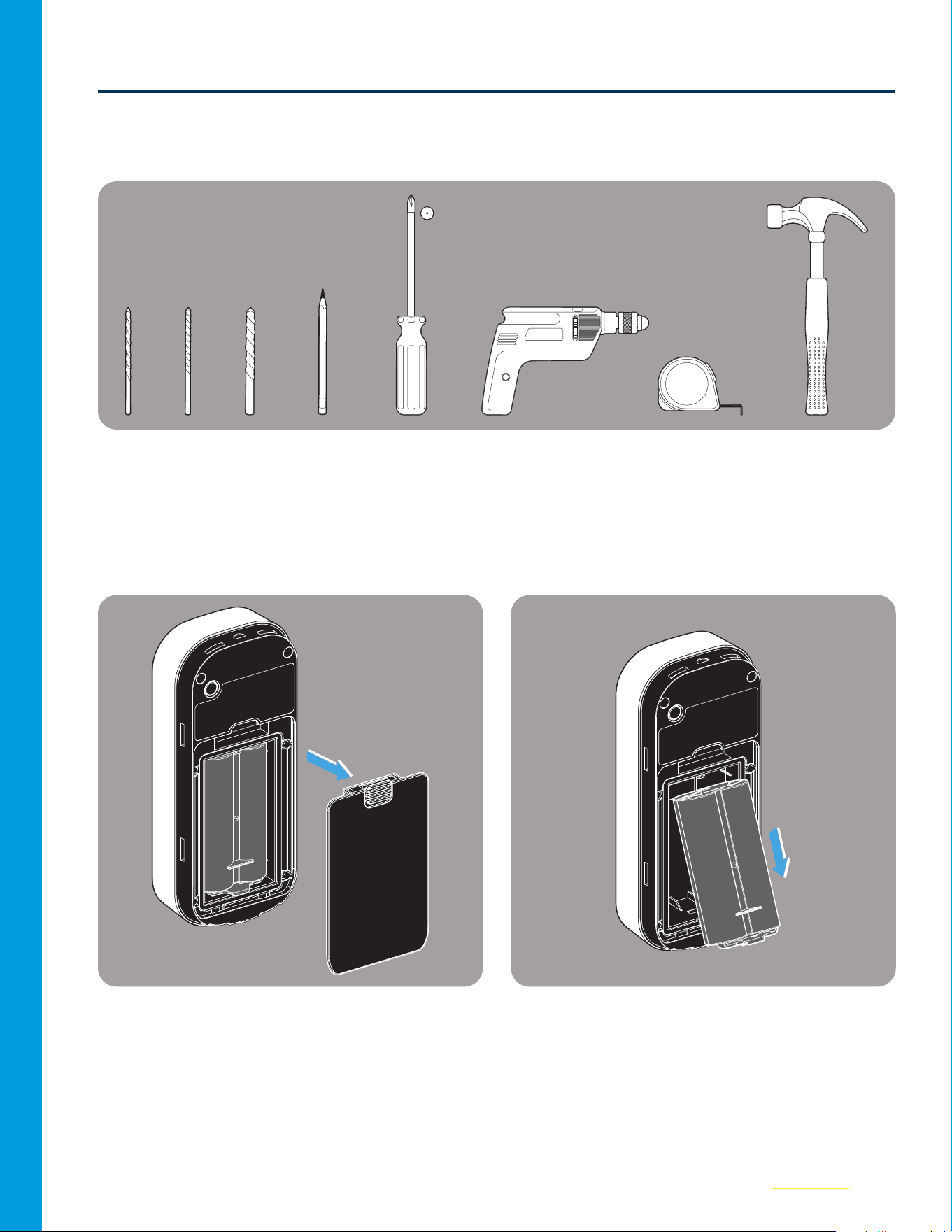
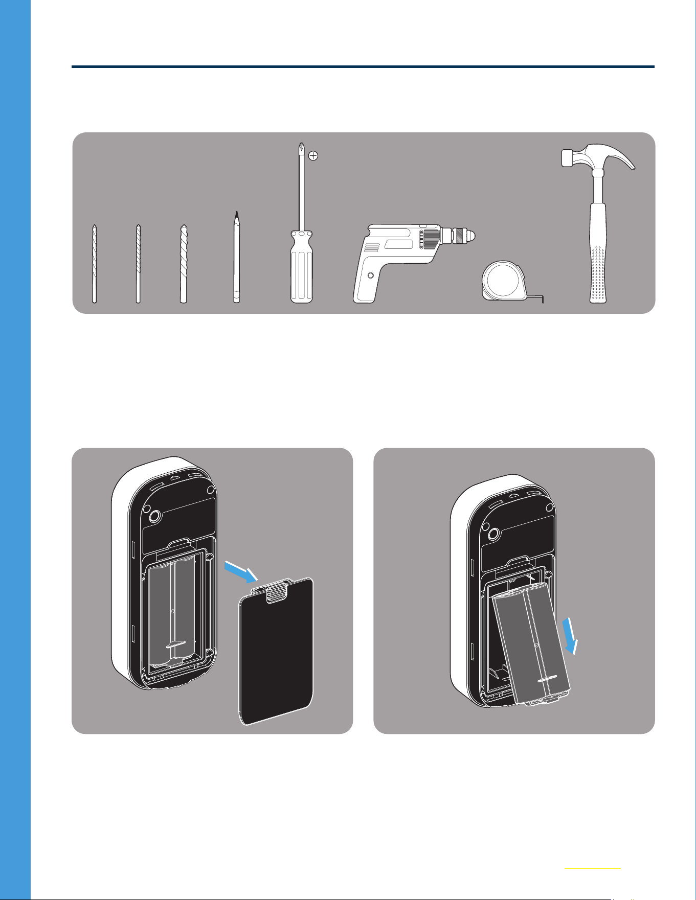
Tools Needed
3/32" 1/4"
Pen Screwdriver Hammer
25’ Measuring TapePower Drill
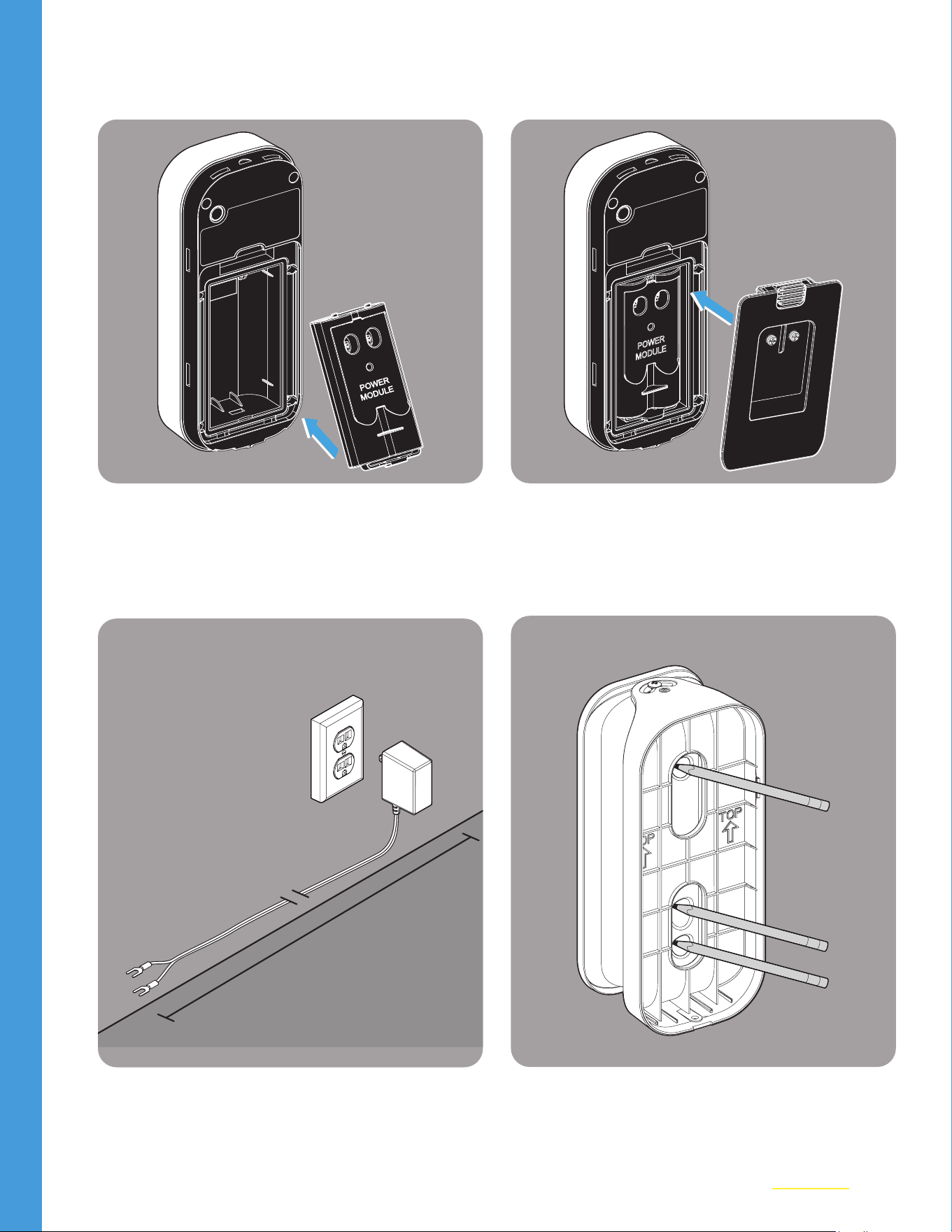
01
Remove the existing Back Cover of the
Video Keypad.
02
Remove the Battery from the Keypad.
7
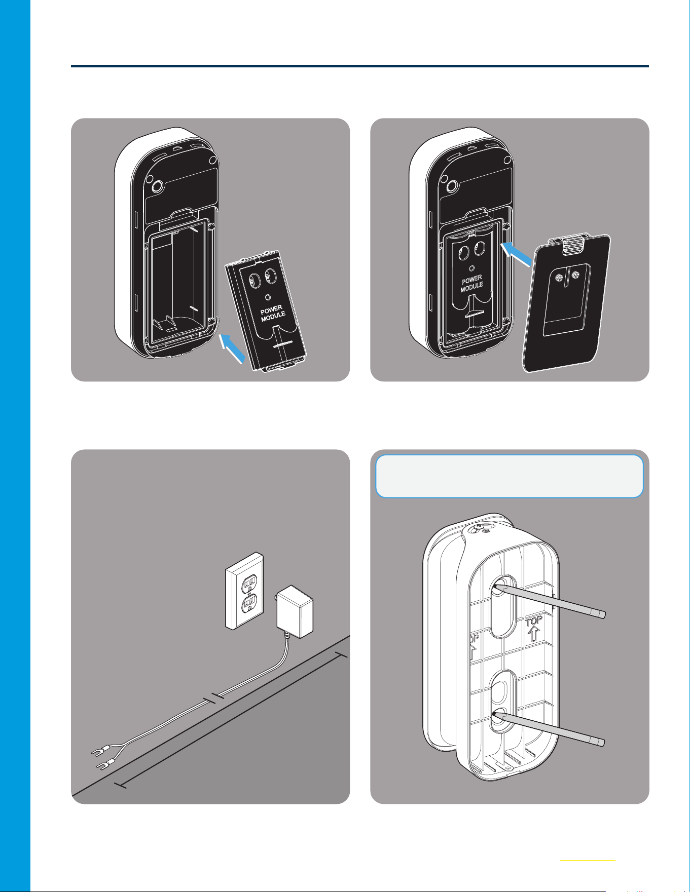
Option 1: External Wire Installation (continued)
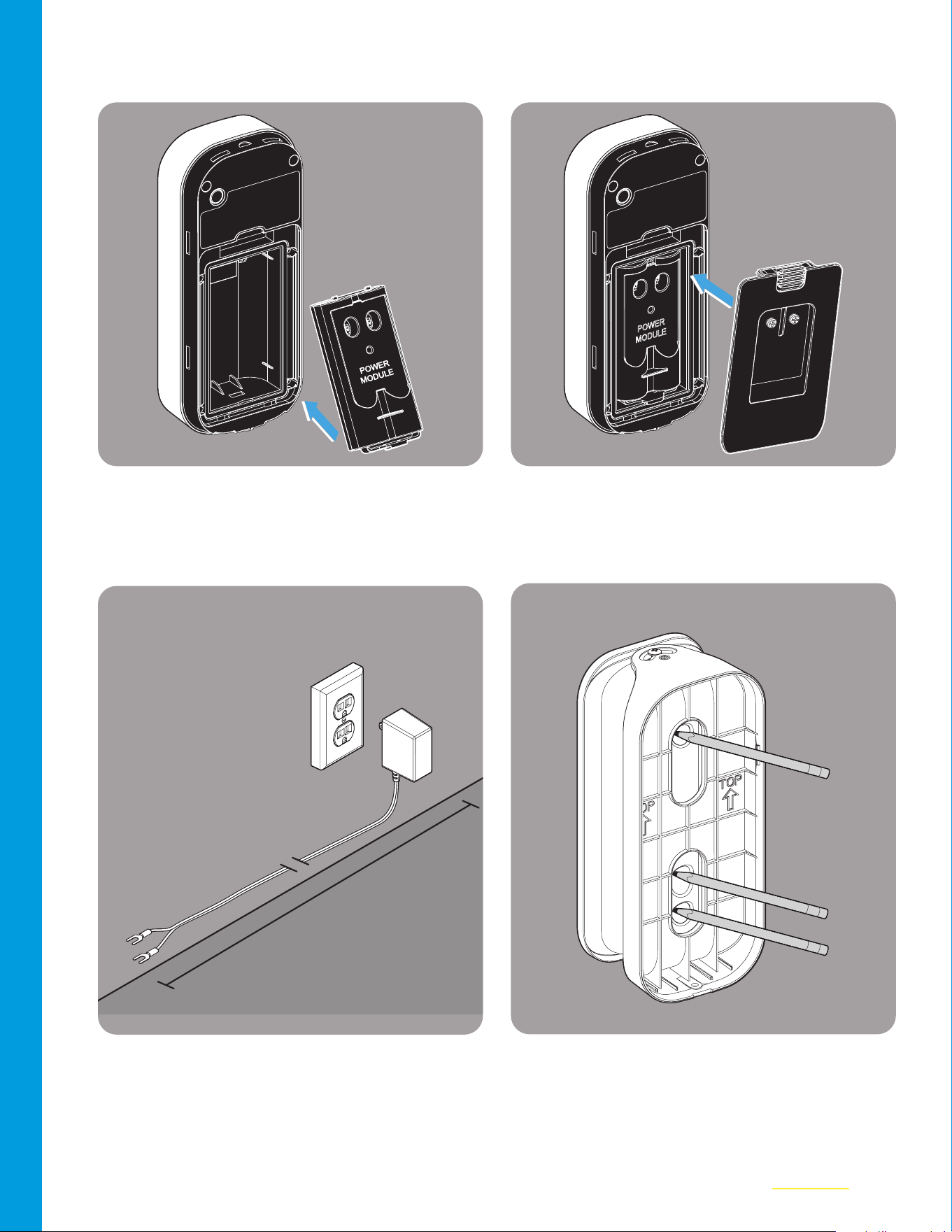
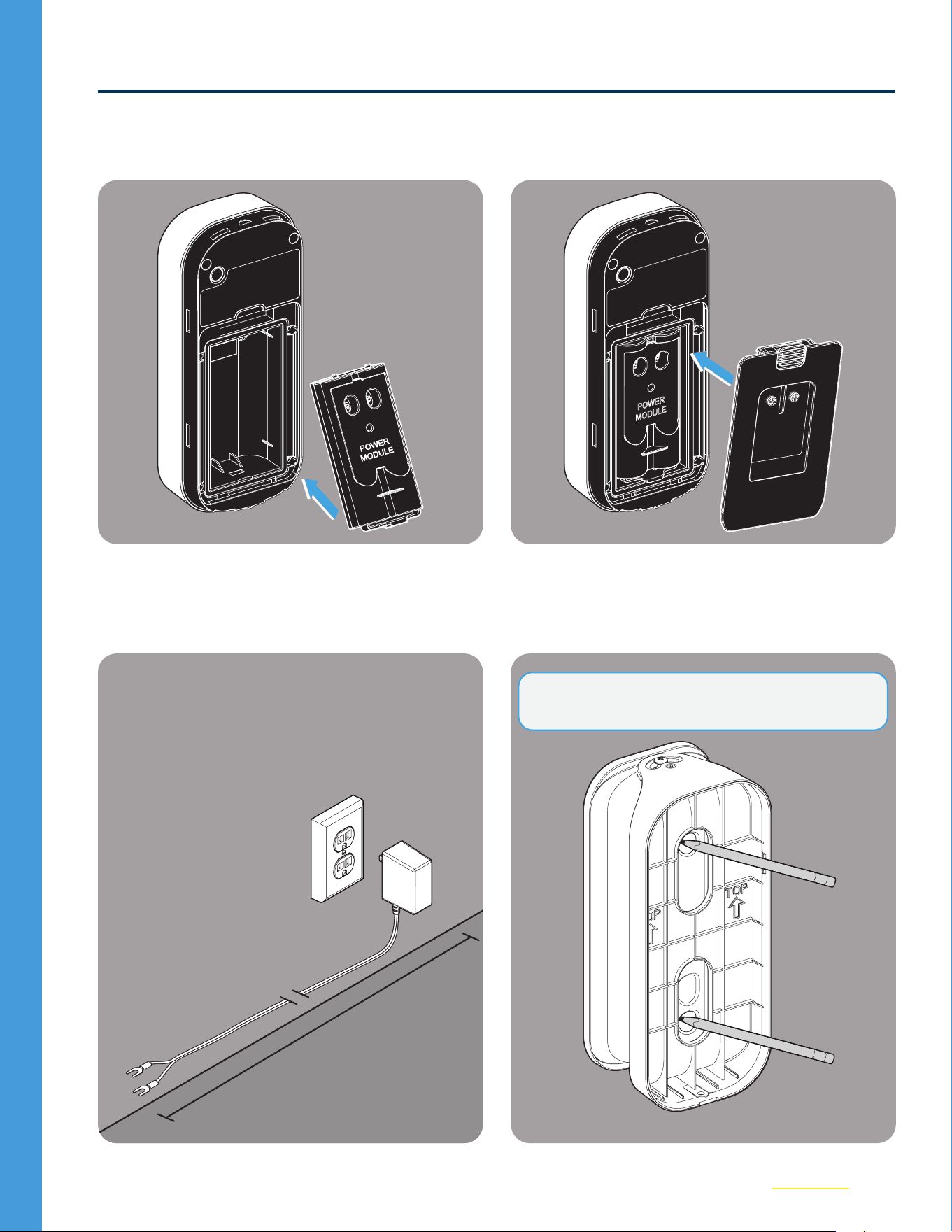
03
Insert the Power Module into the Keypad.
04
Place the new Back Cover over the Power
Module. Set the Keypad aside.
POWER
MODULE
05
Locate the outlet you wish to use (do not
plug in). Lay out the wire along intended
path to check length.
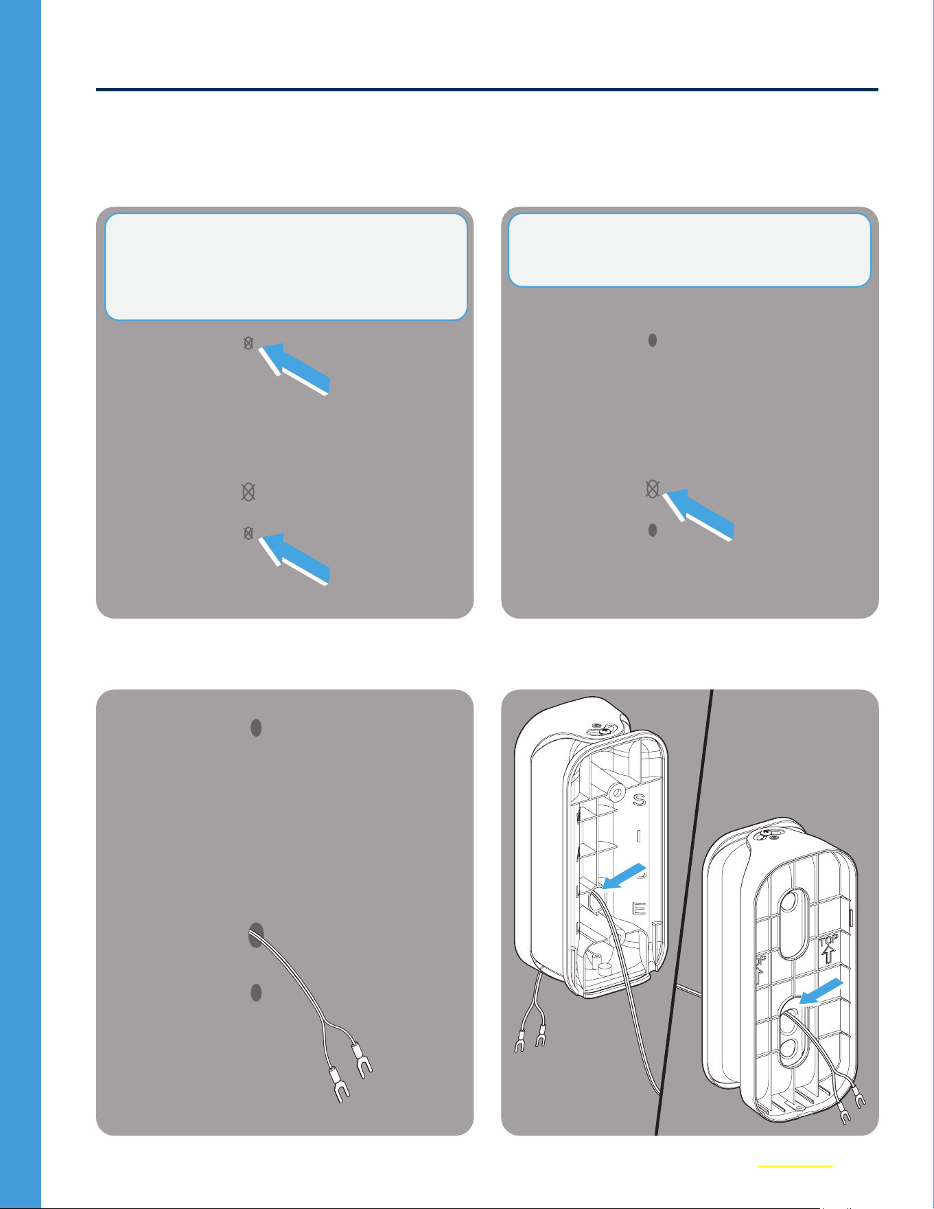
06
Hold the new Swivel Mount up to the wall
and mark the top and bottom holes.
25 ft.
NOTE: If you’re replacing an existing mount,
skipsteps6and 7.
8
Option 1: External Wire Installation (continued)
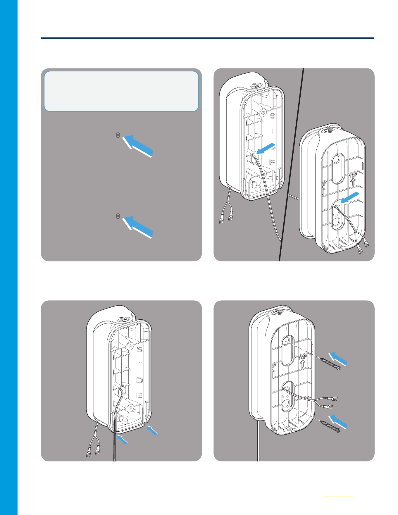
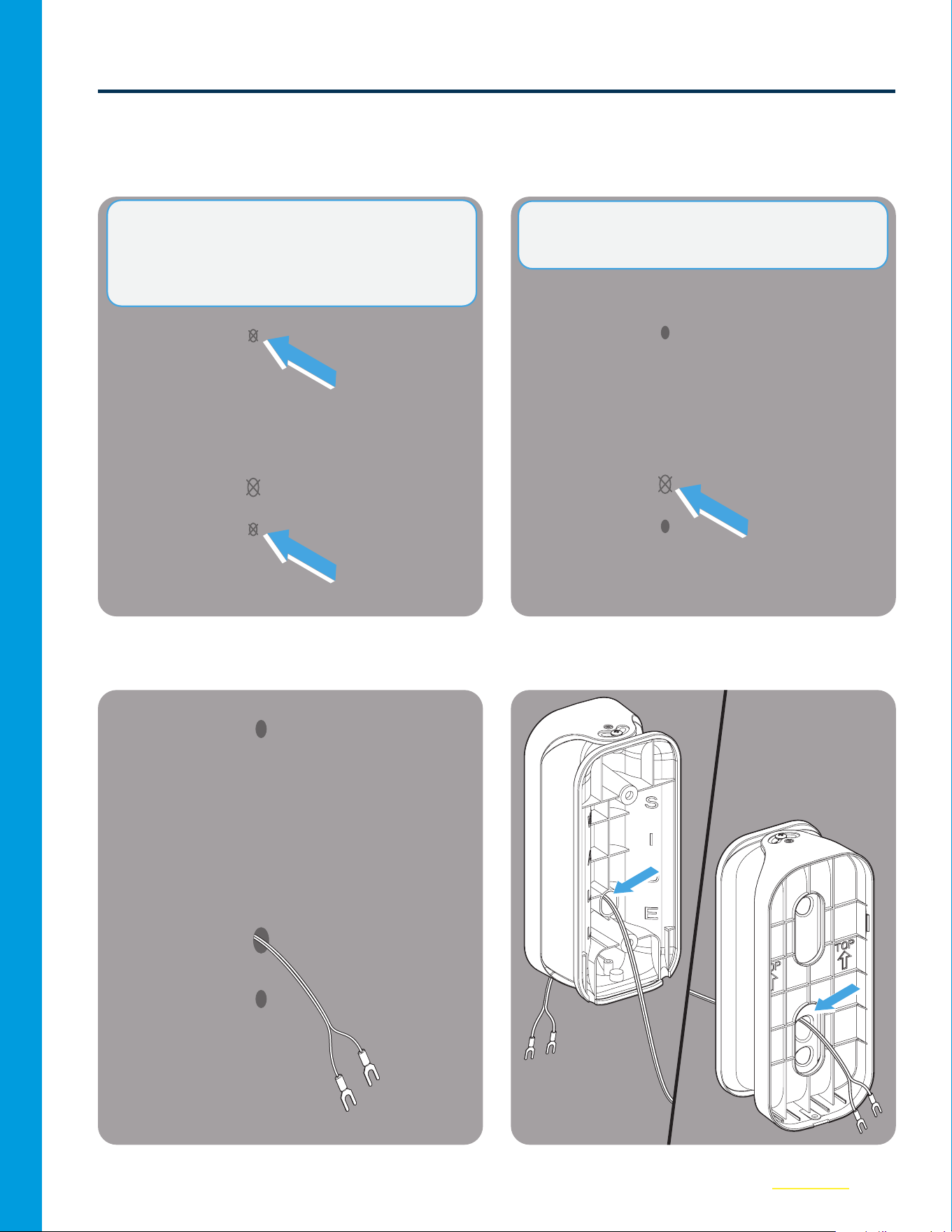
07
Use a 3/32 in. drill bit to drill the top and
bottom holes in the wall.
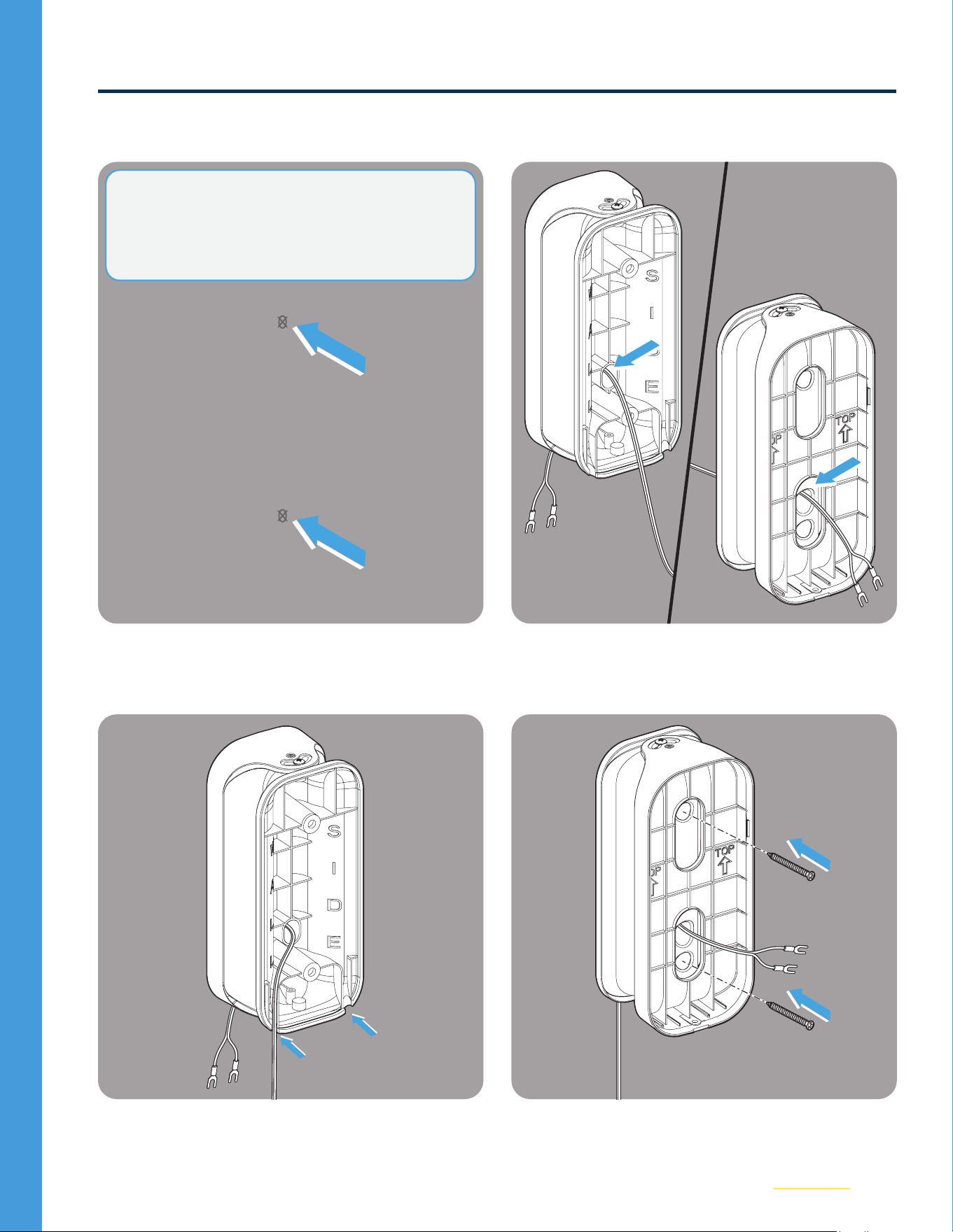
08
Thread the wire from the Wall Side to the
front of the mount as shown below.
09
Make sure the wire is directed through one
of the channels in the back, depending on
if you will route the wire to the right or left.
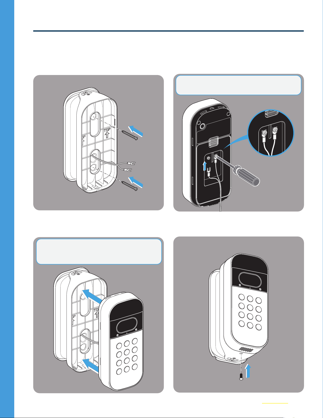
10
Carefully screw the mount into the wall,
making sure not to pinch any wires.
NOTE: If drilling into brick, stucco, or concrete,
use the included wall anchors and a 1/4 in.
masonry bit. Wall anchors are placed in the hole,
and then the screws are screwed in. See step 10.
9
Option 1: External Wire Installation (continued)
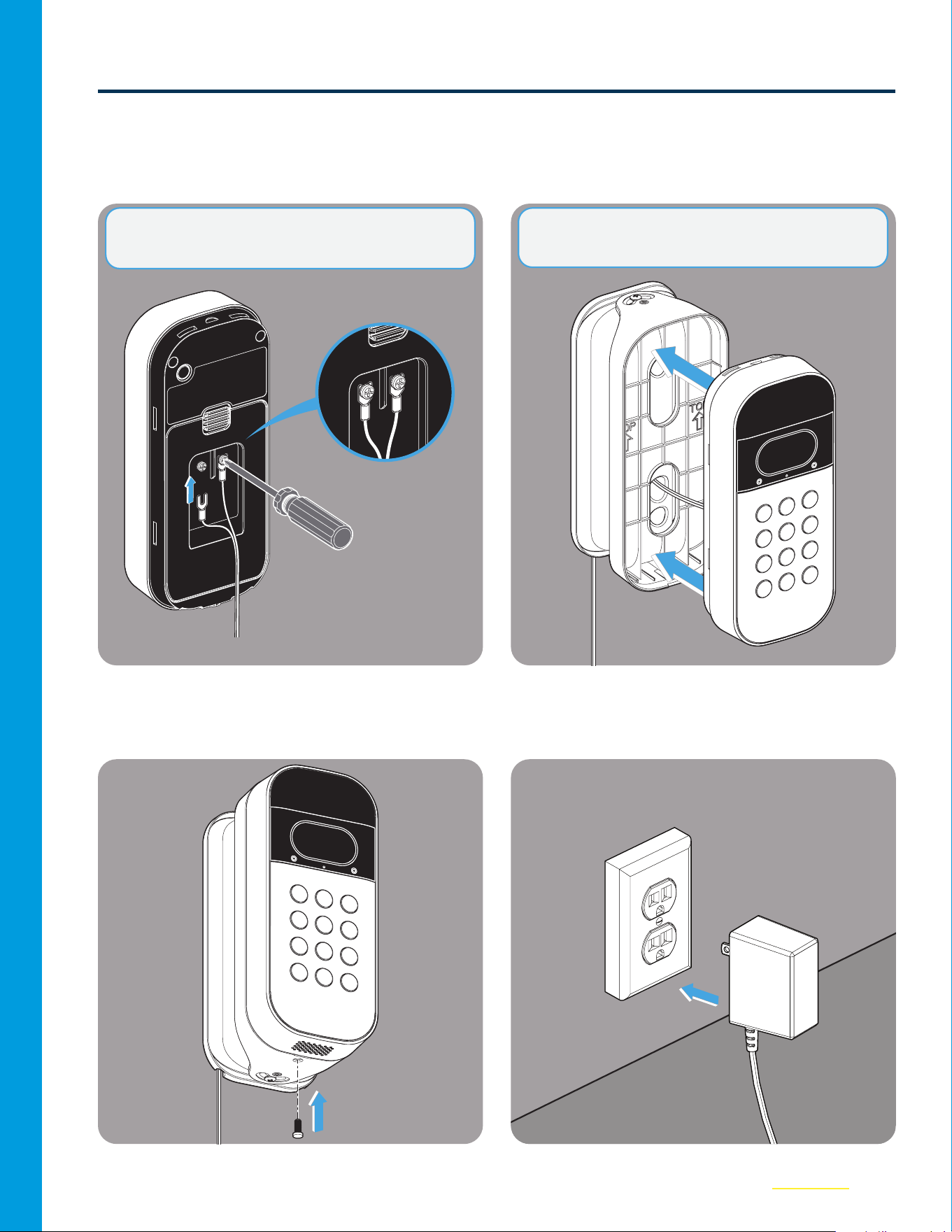
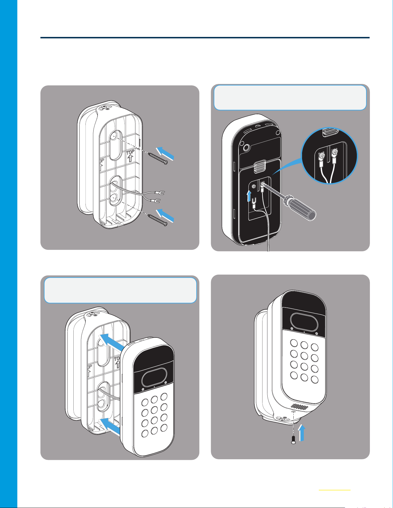
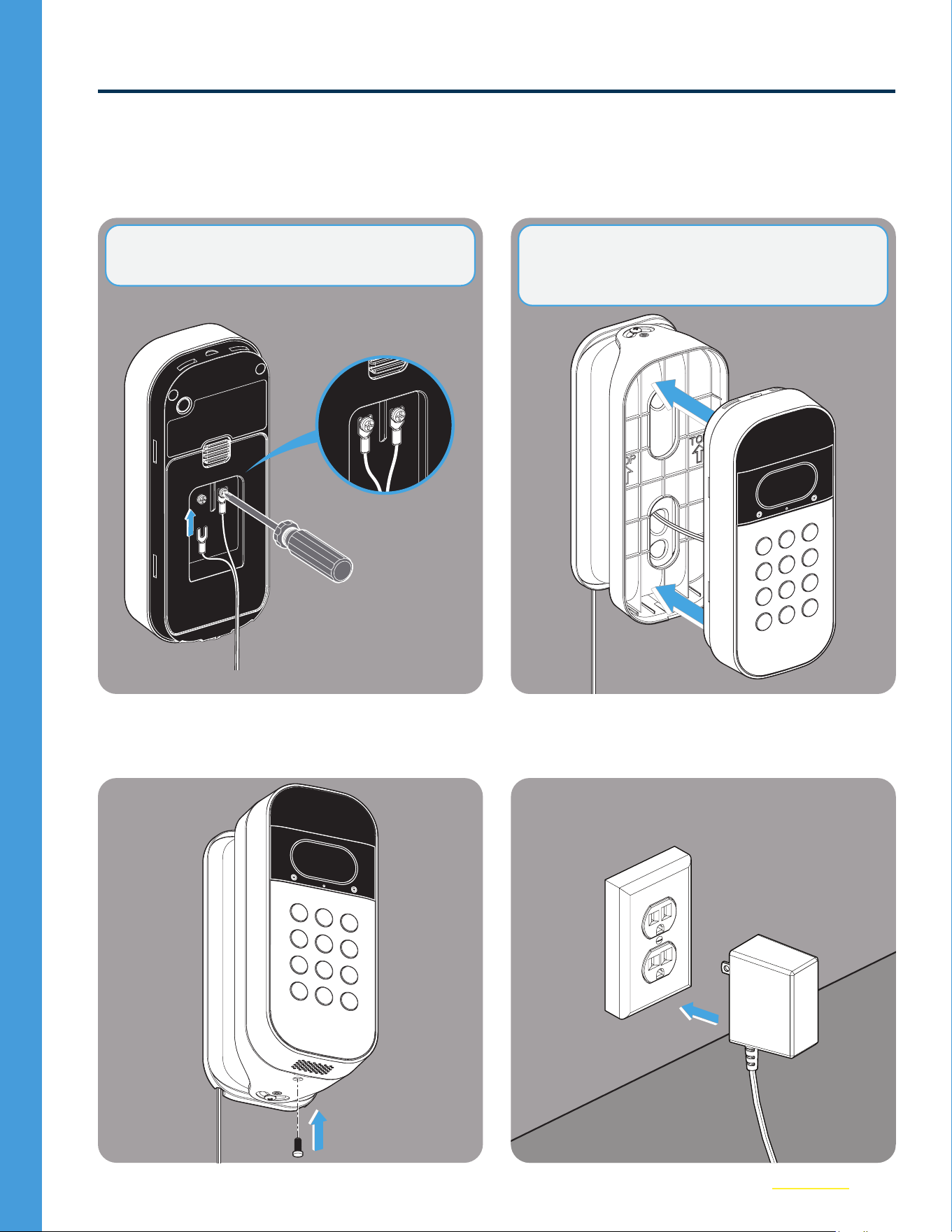
11
Ensure the Power Adapter is NOT plugged
in. Then, use a screwdriver to hand tighten
the wire leads to the screws on the back
cover of your Keypad.
12
Carefully snap the Keypad into the mount,
ensure the wires are NOT pinched..
13
Install the security screw.
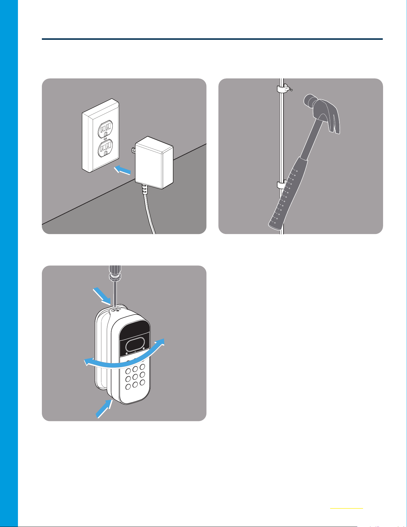
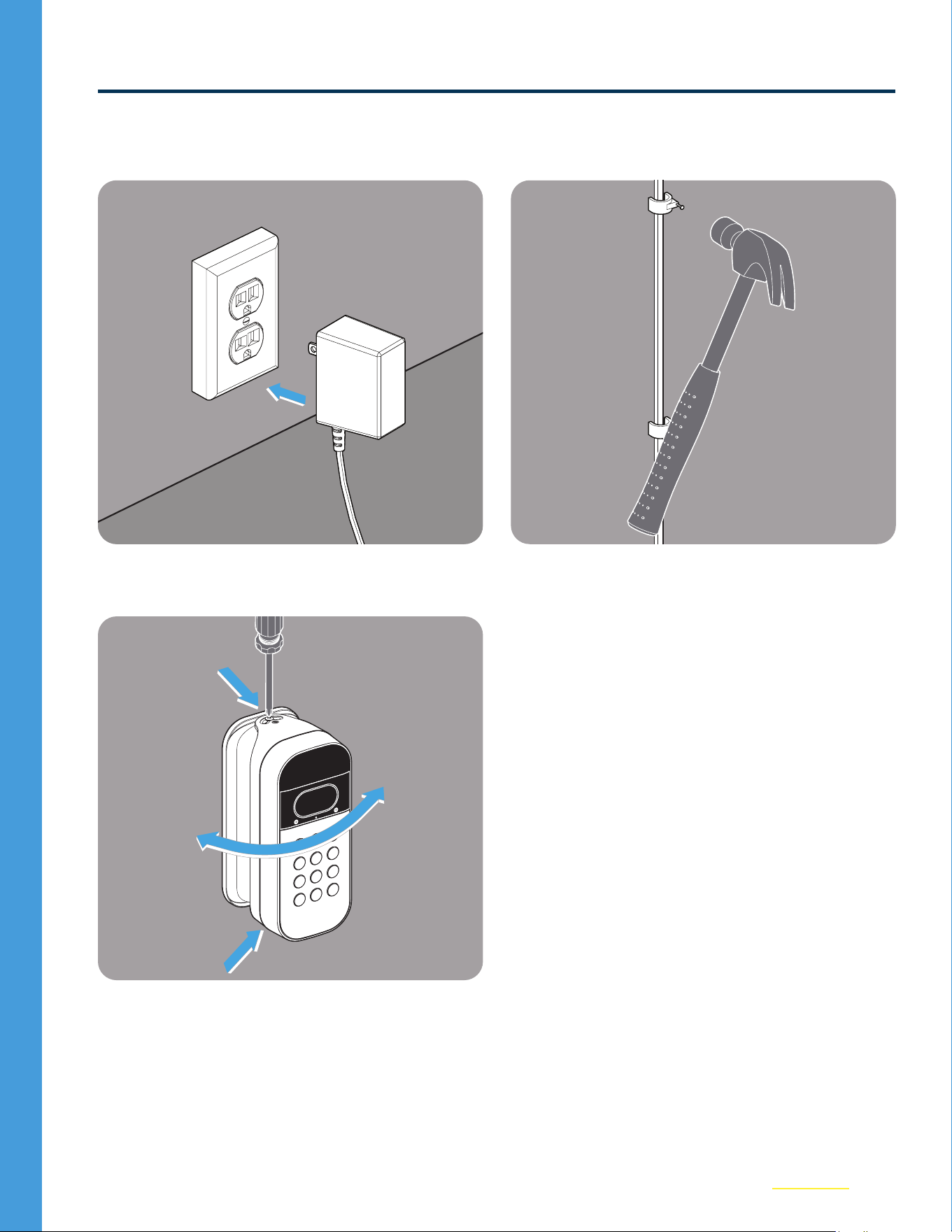
14
Plug in the Power Adapter. Your Keypad
will power up and come back online
automatically.
NOTE: NOT POLARITY SENSITIVE. + / - Can
attach to either screw.
NOTE: Leave 1–2” of slack wire within the mount
to maintain easy access to rear reset button.
10
Option 1: External Wire Installation (continued)
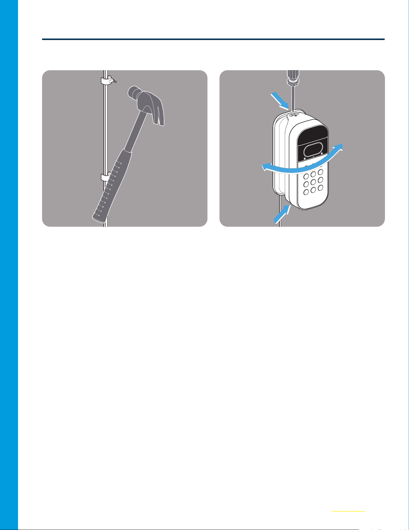
15
Secure the wire along your routed path
with clips as needed.
16
Adjust the angle of view using a Phillips
screwdriver. You are all set to go!
11
Option 2: Through Wire Installation
Tools Needed
3/32" 1/4" 5/16" Pen Screwdriver Hammer25’ Measuring TapePower Drill
01
Remove the existing Back Cover of the
Video Keypad.
02
Remove the Battery from the Keypad.
12
03
Insert the Power Module into the Keypad.
04
Place the new Back Cover over the Power
Module. Set the Keypad aside.
POWER
MODULE
05
Locate the outlet you wish to use (do not
plug in). Lay out the wire along intended
path to check length.
06
Hold the new Swivel Mount up to the wall
and mark all three holes.
25 ft.
13
Option 2: Through Wire Installation (continued)
07
Use a 3/32 in. drill bit to drill the top and
bottom holes in the wall.
08
Use a 5/16 in. drill bit to make the through
hole for the wire to the intended exit point;
this will vary based on your garage frame
conguration.
09
Feed the wire through the larger hole to
the exterior side.
10
Thread the wire from the Wall Side to the
front of the mount as shown below.
NOTE: Be sure the exit path avoids any
obstructions or existing safety sensor wiring.
NOTE: If drilling into brick, stucco, or concrete,
use the included wall anchors and a 1/4 in.
masonry bit. Wall anchors are placed in the hole,
and then the screws are screwed in. See step 11.
14
Option 2: Through Wire Installation (continued)
11
Carefully screw the mount into the wall
making sure not to pinch any wires.
12
Ensure the Power Adapter is NOT plugged
in. Then, use a screwdriver to hand tighten
the wire leads to the screws on the back
cover of your Keypad.
13
Carefully snap the Keypad into the mount,
ensure the wires are NOT pinched.
14
Install the security screw.
NOTE: NOT POLARITY SENSITIVE. + / - Can
attach to either screw.
NOTE: Leave 1–2” of slack wire within the mount
to maintain easy access to rear reset button.
15
Option 2: Through Wire Installation (continued)
15
Plug in the Power Adapter. Your Keypad
will power up and come back online
automatically
16
Secure the wire along your routed path
with clips as needed.
17
Adjust the angle of view using a Phillips
screwdriver. You are all set to go!
114-6041-000
©2024 The Chamberlain Group LLC
Chamberlain, the Chamberlain logo and myQ logo are trademarks, service marks,
and/or registered trademarks of The Chamberlain Group LLC. All rights reserved.
The Chamberlain Group LLC, 300 Windsor Drive, Oak Brook, IL, 60523, United States
KIT ADAPTATEUR
D’ALIMENTATION
DU CLAVIER VIDÉO SMART GARAGE®
Guide de l’utilisateur
du produit et des accessoires

2
Aperçu
Avant d’installer le clavier vidéo
Votre clavier vidéo doit être connecté à l’application myQ avant d’installer le kit adaptateur
d’alimentation. Pour accéder à ces instructions, reportez-vous au guide de l’utilisateur BLEU
fourni dans l’emballage de votre clavier vidéo.
Table des matières
Nous contacter...................................2
Garantie limitée d’un an...........................2
Contenu de la boîte...............................3
Désinstaller le support actuel.....................4
Choisir l’acheminement du câble .................5
Option1: Installation d’un câble extérieur ........6
Option2: Installation d’un câble intérieur.......10
IMPORTANT:
Avez-vous déjà installé un clavier vidéo?
OUI - Passez à la page 4.
NON - Passez à la page 5.
Ressources supplémentaires
Nous contacter
Pour toute information ou assistance supplémentaire, veuillez consulter le site: support.chamberlaingroup.com
Ou appelez-nous: +1 (800) 528-5880
Garantie limitée d’un an
The Chamberlain Group LLC ("Vendeur") garantit au premier acheteur de ce produit, pour la résidence dans
laquelle ce produit est installé à l’origine (sauf si la loi applicable l’interdit (ce qui peut inclure la province
de Québec)), qu’il est exempt de défauts de matériaux et/ou de fabrication pendant une période d’un an à
compter de la date d’achat. Le bon fonctionnement de ce produit dépend du respect de ces instructions en
ce qui a trait l’installation, le fonctionnement, l’entretien et les tests. La garantie ne couvre pas les dommages
ou défauts résultant du non-respect strict de ces instructions. Le Vendeur ne pouvant contrôler la qualité
des produits vendus par des vendeurs non autorisés, la présente garantie limitée ne s’applique qu’aux
Produits achetés auprès du Vendeur ou d’un revendeur autorisé aux États-Unis ou au Canada, sauf si la
loi l’interdit. Le Vendeur se réserve le droit de rejeter les demandes de garantie des acheteurs pour des
produits achetés auprès de vendeurs non autorisés, y compris des sites Internet non autorisés. Veuillez
vous référer à l’étiquette de la batterie pour la recycler et la mettre au rebut correctement.
Pour plus d’informations, visitez le site www.myq.com/warranty
3
Contenu de la boîte
Module
d’alimentation (1)
Couverture arrière (1)
Vis de sécurité
(1)
Ancrage mural
(1)
câble d’alimentation
de 25pi (1)
Vis de support
de 1po (2)
Support pivotant du kit
adaptateur d’alimentation (1)*
Serre-câble (20)
*Il faut utiliser le support fourni pour permettre une bonne gestion des câbles.
4
Désinstaller le support actuel
01
Retirez la vis de sécurité du clavier vidéo.
02
Retirez le clavier du support fixe ou
pivotant existant.
03
Retirez les deux vis de fixation du support
fixe et retirez-le du mur.
REMARQUE: Cette étape s’applique aux supports
pivotants et fixes.
REMARQUE: Le support fixe NE FONCTIONNE
PAS avec le kit adaptateur d’alimentation. Veuillez
utiliser le support pivotant fourni.
5
Choisir l’acheminement du câble
Le kit adaptateur d’alimentation offre deux options pour gérer le cordon d’alimentation.
• Option 1 - Installation d’un câble extérieur: Le câble d’alimentation est acheminé en bas à
gauche ou à droite du support, puis le long du mur extérieur, en passant par le cadre de la porte
de garage, jusqu’à une prise intérieure. (Voir page6).
• Option 2 - Installation d’un câble intérieur: Le câble d’alimentation passe directement à travers
le mur jusqu’à une prise intérieure pour un aspect extérieur sans câble. (Voir page11).
Décidez de l’option qui vous convient le mieux, en vous assurant que le chemin jusqu’à la prise
disponible est inférieur à 25pieds, puis passez à cette étape.
Option1: Installation d’un câble
extérieur
Option2: Installation d’un câble
intérieur

6
Option1: Installation d’un câble extérieur
Outils nécessaires
3/32po 1/4po Stylo Tournevis MarteauRuban à mesurer
de 25pi
Perceuse
électrique
01
Retirez le couvercle arrière du clavier vidéo.
02
Retirez le ruban de la poulie de tension.
7
Option1: Installation d’un câble extérieur (suite)
03
Insérez le module d’alimentation dans le
clavier.
04
Placez le nouveau couvercle arrière sur
le module d’alimentation. Mettez le clavier
de côté.
POWER
MODULE
05
Localisez la prise de courant que vous
souhaitez utiliser (ne la branchez pas).
Disposez le câble le long de l’acheminement
prévu pour vérifier la longueur.
06
Tenez le nouveau support pivotant contre
le mur et marquez les trous supérieurs et
inférieurs.
25 pi
REMARQUE: Si vous remplacez un support
existant, sautez les étapes 6 et 7.
8
Option1: Installation d’un câble extérieur (suite)
07
Utilisez une mèche de 3/32po pour percer
les trous supérieurs et inférieurs dans le mur.
08
Faites passer le câble du côté du mur à l’avant
du support, comme indiqué ci-dessous.
09
Veillez à ce que le câble passe par l’un des
canaux situés à l’arrière, selon que vous
l’acheminez vers la droite ou vers la gauche.
10
Vissez soigneusement le support dans le
mur, en veillant à ne pas pincer les câbles.
REMARQUE: Si vous percez des briques, du
stuc ou du béton, utilisez les ancrages muraux
fournis et une mèche de maçonnerie de 1/4po.
Lesancrages sont placés dans le trou, puis les
vis sont vissées. Voir l’étape10.
9
Option1: Installation d’un câble extérieur (suite)
11
Assurez-vous que l’adaptateur
d’alimentation n’est PAS branché.
Ensuite,à l’aide d’un tournevis, serrez
àlamain les câbles conducteurs sur
lesvissituées à l’arrière du clavier.
12
Enclenchez délicatement le clavier dans le
support, en veillant à ce que les câbles ne
soient PAS pincés.
13
Installez la vis de sécurité.
14
Branchez l’adaptateur d’alimentation.
Le clavier s’allume et se remet en ligne
automatiquement.
REMARQUE: NON SENSIBLE À LA POLARITÉ.
+/- peut se fixer sur l’une ou l’autre des vis.
REMARQUE: Laissez 1 à 2po de câble détendu
dans le support pour faciliter l’accès au bouton
de réinitialisation arrière.

10
Option1: Installation d’un câble extérieur (suite)
15
Fixez le câble le long du chemin tracé à
l’aide de clips si nécessaire.
16
Réglez l’angle de vue à l’aide d’un tournevis
cruciforme. Vous êtes prêt!
11
Option2: Installation d’un câble intérieur
Outils nécessaires
3/32po 1/4po
5/16po
Stylo
Tournevis MarteauRuban à mesurer
de 25pi
Perceuse
électrique
01
Retirez le couvercle arrière du clavier
vidéo.
02
Retirez le ruban de la poulie de tension.
12
03
Insérez le module d’alimentation dans le
clavier.
04
Placez le nouveau couvercle arrière sur
le module d’alimentation. Mettez le clavier
de côté.
POWER
MODULE
05
Localisez la prise de courant que vous
souhaitez utiliser (ne la branchez pas).
Disposez le câble le long de l’acheminement
prévu pour vérifier la longueur.
06
Tenez le nouveau support pivotant contre
le mur et marquez les trois trous.
25 pi
13
Option2: Installation d’un câble intérieur (suite)
07
Utilisez une mèche de 3/32po pour percer
les trous supérieurs et inférieurs dans le mur.
08
Utilisez une mèche de 5/16 popour percer
le trou de passage du câble jusqu’au point
de sortie prévu ; celui-ci variera en fonction
de la configuration de l’encadrement de
votre garage.
09
Faites passer le câble par le trou le plus
large vers l’extérieur.
10
Faites passer le câble du côté du mur à l’avant
du support, comme indiqué ci-dessous.
REMARQUE: Veillez à ce que l’acheminement de
sortie évite toute obstruction ou tout câblage de
capteur de sécurité existant.
REMARQUE: Si vous percez des briques, du
stuc ou du béton, utilisez les ancrages muraux
fournis et une mèche de maçonnerie de 1/4po.
Lesancrages sont placés dans le trou, puis les
vis sont vissées. Voir l’étape 11.
14
Option2: Installation d’un câble intérieur (suite)
11
Vissez soigneusement le support dans le
mur, en veillant à ne pas pincer les câbles.
12
Assurez-vous que l’adaptateur
d’alimentation n’est PAS branché. Ensuite,
à l’aide d’un tournevis, serrez à la main les
câbles conducteurs sur les vis situées à
l’arrière du clavier.
13
Enclenchez délicatement le clavier dans le
support, en veillant à ce que les câbles ne
soient PAS pincés.
14
Installez la vis de sécurité.
REMARQUE: NON SENSIBLE À LA POLARITÉ.
+/- peut se fixer sur l’une ou l’autre des vis.
REMARQUE: Laissez 1 à 2po de câble détendu
dans le support pour faciliter l’accès au bouton
de réinitialisation arrière.
15
Option2: Installation d’un câble intérieur (suite)
15
Branchez l’adaptateur d’alimentation.
Le clavier s’allume et se remet en ligne
automatiquement
16
Fixez le câble le long du chemin tracé
àl’aide de clips si nécessaire.
17
Réglez l’angle de vue à l’aide d’un tournevis
cruciforme. Vous êtes prêt!
114-6041-000
©2024 The Chamberlain Group LLC
Chamberlain, le logo Chamberlain et le logo myQ sont des marques commerciales, des marques
de service et/ou des marques déposées de The Chamberlain Group, LLC. Tous droits réservés.
The Chamberlain Group, LLC 300 Windsor Drive Oak Brook, IL, 60523, États-Unis