Model: SP35344
USER'S MANUAL
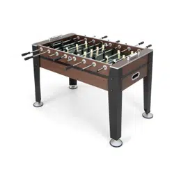
54” Soccer Table
1
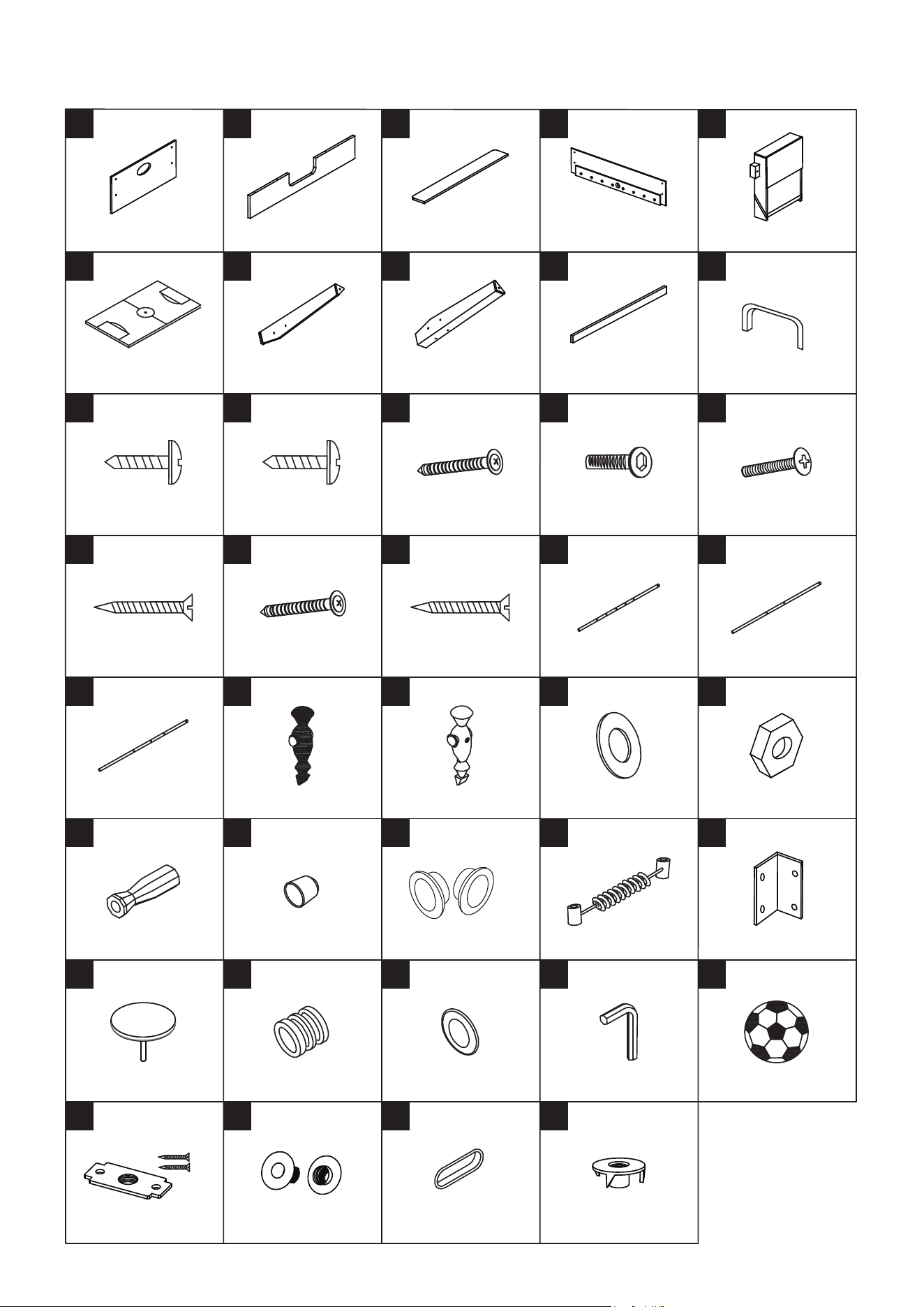
SP35344 PARTS LIST
End Apron
2 Pieces
Goal End Board
2 Pieces
Top Slat Board
2 Pieces
Side Apron
2 Pieces
Playfield
1 Piece
Left Leg
2 Pieces
4 x 10mm
Round Head Screw
64 Pieces
3 x 20mm
Washer Head Screw
18 Pieces
4 x 32mm
Round Head Screw
4 Pieces
Support Brace
2 Pieces
Right Leg
2 Pieces
4 x 28mm Bolt
26 Pieces
4 x 45mm
Flat Head Screw
4 Pieces
5/16” x 1” Bolt
16 Pieces
1 2 3 4 5
6 7 8 9 10
11 12 13 14 15
16 17 18 19 20
21 22 23 24 25
26 27 28 29 30
31 32 33 34 35
36 37 38 39
Goal Box
2 Pieces
2-Hole Rod
2 Pieces
4 x 40mm
Flat Head Screw
12 Pieces
Pre-installed
Pre-installed
5-Hole Rod
2 Pieces
Pre-installed
Pre-installed
3 x 30mm
Washer Head Screw
8 Pieces
3-Hole Rod
4 Pieces
4mm Nut
26 Pieces
Player - Ivory
13 Pieces
5/16” Washer
16 Pieces
Player - Black
13 Pieces
Handle
8 Pieces
“L” Bracket
16 Pieces
Plastic Ball Entry Rim
2 Pieces
Scorer
2 Pieces
Rod End Cap
8 Pieces
Leg Leveler
4 Pieces
Soccer Ball
2 Pieces
Rod Washer
16 Pieces
Allen Key
1 Piece
Rod Bumper
16 Pieces
Square Nut with Screws
4 Pieces
Ball Return Cover
2 Pieces
T - Nut
16 Pieces
Goal Cover
2 Pieces
Plastic Rod Bushing
16 Pieces
Pre-installed
Pre-installed
2
FIG.1
ASSEM B LY I N STRUCTIONS
1. Find a clean, level place to begin the assembly of your Soccer Table. The table will be assembled upside down
and then turned over on its legs once the assembly completed. This game table is heavy, and turning it over will
require at least two strong adults.
2. Remove all the parts from the box and verify that you have all of the listed parts as shown on the parts list. Care-
fully cut or tear the four corners of the box so that the bottom of the box can be used as your work surface.
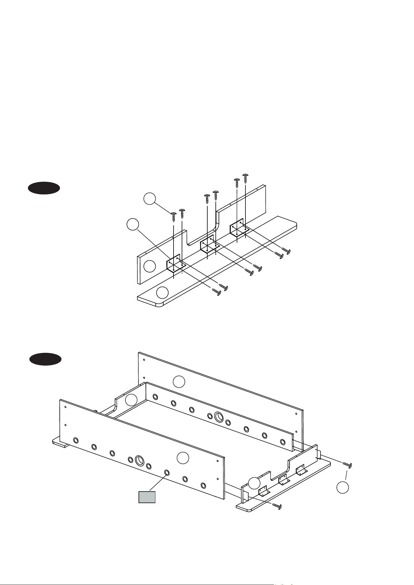
3. Attach one Goal End Board (#2) to one Top Slat Board (#3) using three “L” Brackets (#30) and twelve Screws
(#11) as shown in FIG.1.
4. Repeat the step above for the other Goal End Board (#2) and Top Slat Board (#3).
FIG. 1
FIG.2
5. Attach the pre-assembled Goal End Boards and Top Slat Boards (#2 & #3) to the Side Aprons (#4) using eight
Screws (#17).
FIG. 2
2
30
11
3
2
2
17
4
4
37
3
FIG.3
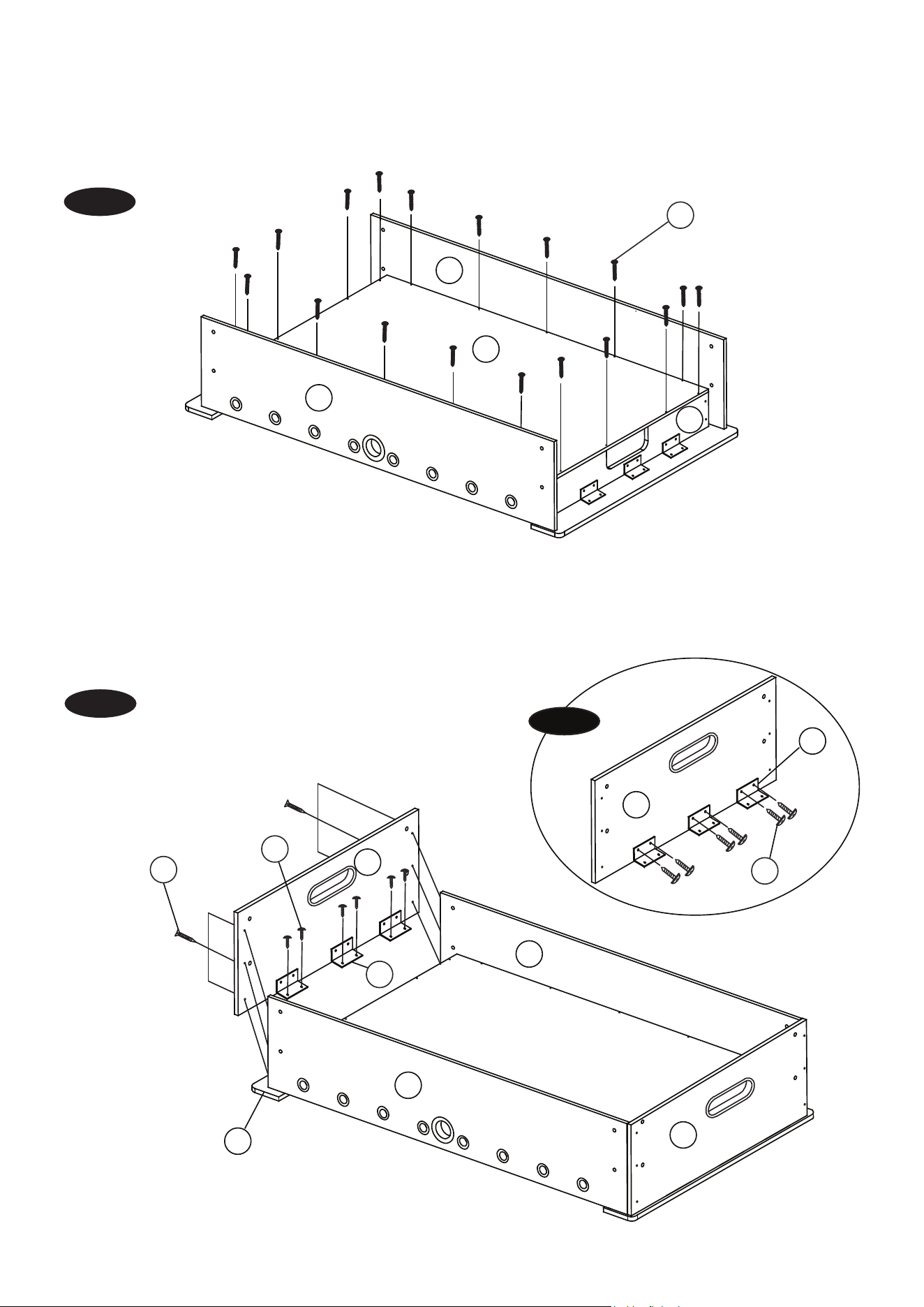
6. Place the Playfield (#6) in the center of the cabinet. Attach it to the Side Aprons (#4) using ten Screws (#13) and
attach it to the Goal End Boards (#2) using eight Screws (#13).
FIG. 3
FIG.4
7. Attach the “L” Brackets (#30) to the End Aprons (#1) using two Screws (#11) per Bracket as shown in FIG.4A.
8. Attach the End Aprons (#1) to the Side Aprons (#4) using six Screws (#18) per End Apron, and then attach the
“L” Brackets (#30) to the Top Slat Boards (#3) using two Screws (#11) per Bracket. See FIG.4.
FIG. 4
18
30
11
11
1
4
3
4
1
1
13
4
2
4
6
FIG. 4A
30
4
FIG.5
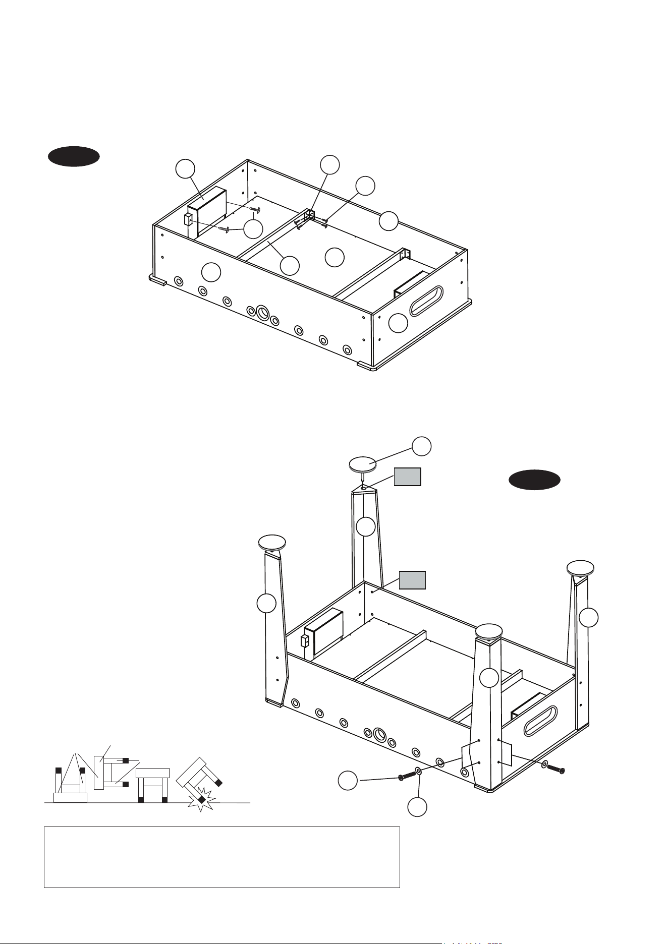
9. Attach the Goal Boxes (#5) to the End Aprons (#1) using two Screws (#12) per Goal Box.
10. Place the Support Braces (#9) on the Playfield (#6) and attach them to Side Aprons (#4) using two “L” Brackets
(#30) and eight Screws (#11) per Support Brace.
FIG. 5
FIG.6
11. Attach the Left and Right Legs (#7 & #8) to the corner of the cabinet using four Bolts (#14) and four Washers
(#24) per Leg.
12. Screw the Leg Levelers (#31) into the bottom of each Leg.
13. Lift the table assembly from the floor with
two strong adults, turn it over, and set table
on its legs in the location where you play.
Go back and make sure that all connec-
tions are tight.
FIG. 6
HOLD TABLE
CABINET
DO NOT
HOLD THE
LEGS
DO NOT LEAN THE
TABLE ON ITS LEGS!
CAUTION: Two strong adults are recommended to turn the table over as shown.
1. Lift the table off the ground.
2. Turn the table over.
3. Place it on all four feet at the same time on the ground.
30
11
5
4
4
1
6
9
12
31
14
24
7
8
7
8
39
36
5
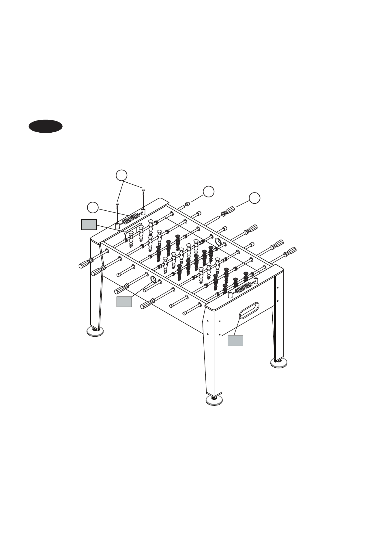
FIG.7
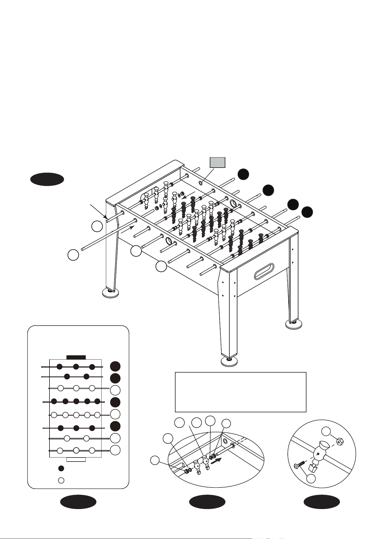
14. Slide the Player Rods ( #19-21) through the Rod Bushings (#37) on one Side Apron (#4) in the order as
shown in Fig.7 and 7A.
Note: The player Rods have a hole at their end where the Handles (#26) will go.
15. Place the Rod Bumpers (#32), Rod Washers (#33) and Players (#22 and #23) onto the Player Rods (#19,
#20 and #21) in the order as shown in Fig.7, 7A and 7B.
16. Now insert the Player Rods through the Rod Bushings (#37) on the opposite Side Apron (#4).
17. Attach the Players (#22 or #23) to the Player Rods (#19 -21) using one Bolt (#15) and one Nut (#25) per
Player. See FIG.7C.
Note: The goalie should be at the left side of each player.
FIG.7
Note: Players of the same team color
should have Handles (#26) on the
same side, and each team’s players
should be facing their opponent.
ORDER OF PLAYERS
(Overhead View)
21
21
21
21
19
19
20
20
= BLACK
= IVORY
FIG. 7A
15
25
FIG. 7C
37
21
19
20
21
21
19
20
21
The Hole
FIG. 7B
32
32
33
33
22 23
or
6
YOU ARE NOW READY TO PLAY!
FIG.8
FIG.8
18. Place the Handles (#26) onto the Player Rods with a hole at their end. And then place the Rod End Caps (#27)
onto the other side of the Player Rods.
19. Attach the two Scorers (#29) to the Top Slat Board (#3) using two Screws (#16) per Scorer.
38
28
29
16
26
27
10

TIPS:
Your suggestions and comments for Costway are really important to us!
We sincerely solicit you to go back to our shop and leave a good rating in just a
simple click. It would be quite encouraging if you could kindly do so like below:
February 24, 2018
Great product so far. Fast delivery, easy setup, and working without any issues.
Great products so far
With your inspiring rating, Costway will be more consistent to offer you
EASY SHOPPING EXPERIENCE, GOOD PRODUCTS and EFFICIENT SERVICE!
UNITED STATES
CANADA
UNITED KINGDOM
GERMANY
FRANCE
ITALY
SPAIN
JAPAN
RUSSIA
AUSTRALIA
US office:Fontana
UK office:Ipswich