
Loading ...
Loading ...
Loading ...
7Section 2 — ASSembly & Set-Up
2. Remove the plastic cover, if present, from the
negative battery terminal and attach the black
cable to the negative battery terminal (–) with the
bolt (a) and hex nut (b). See Figure 2-2.
3. Position the red rubber boot (c) over the positive
battery terminal to help protect it from corrosion.
Note: If the battery is put into service after the
date shown on top/side of battery, charge the
battery as instructed in the Service section your
Operator’s Manual on page 8 prior to operating
the tractor.
Shipping Brace Removal
WARNING
Make sure the tractor’s engine is OFF, remove the ignition key, and
set the parking brake before removing the shipping brace. Refer
to the Controls & Operations section on page 8 for instructions on
how to set the parking brake.
Check the cutting deck for a shipping brace (a) that
may be holding the chute deflector (b) upward for
shipment. If the shipping brace (a) is present, it must
be removed before operating the tractor. Holding the
chute deflector (b) fully upward, remove the shipping
brace (a). Lower the chute deflector (b) and discard the
shipping brace (a). See Figure 2-3.
(a)
(b)
Figure 2-3
WARNING
The shipping brace (a) is used for packaging purposes only, it must
be removed and discarded before operating your tractor.
WARNING
The cutting deck is capable of throwing objects. Failure to
operate the tractor without the chute deflector in the proper
operating position could result in serious personal injury and/or
property damage.
Attaching the Steering Wheel
1. If the steering wheel (a) for your tractor did not
come attached, the hardware for attaching it
has been packed within the steering wheel (a),
beneath the steering wheel cap (b). Carefully
pry OFF the steering wheel cap (b) and remove
the cupped washer (c) and hex bolt (d).
(d)
(b)
(a)
(e)
(c)
Figure 2-4
2. With the wheels of the tractor pointing straight
forward, place the steering wheel (a) over the
steering shaft (e).
3. Place the cupped washer (c) -- cupped side
down -- over the steering wheel (a) and secure
with the hex bolt (d). See Figure 2-4.
4. Place the steering wheel cap (b) over the center
of the steering wheel (a) and push downward
until it “clicks” into place.
Attaching the Seat
If the seat for your tractor was not attached at the
factory, refer to the following steps.
Note: For shipping reasons, seats are either fastened
to the tractor seat’s pivot bracket with a cable tie, or
mounted backward to the pivot bracket. In either case,
remove the seat from its shipping position.
1. Remove the seat adjustment knob/bolt (a) from
the bottom of the seat (b). See Figure 2-5.
(a)
(b)
(c)
Figure 2-5
2. Align the seat (b) over the seat pivot bracket (c) as
shown in Figure 2-5 and fit the seat (b) onto the
seat pivot bracket (c) inserting the two tabs (square
or round) on the seat (b) bottom into the slots on
the seat pivot bracket (c).
3. Slide the seat (b) rearward in the seat pivot
bracket (c), lining up the center rear slot in the
seat pivot bracket (c) with the remaining hole in
the seat (b) base. See Figure 2-6.
(b)
(c)
(a)
Figure 2-6
Note: Be certain the two seat tabs (square or
round) engage the seat pivot bracket as shown
in the bottom right inset of Figure 2-6.
4. Select the desired position for the seat (b),
and secure with the adjustment knob/bolt (a)
removed in Step 1. See Figure 2-6.
5. To adjust the position of the seat, remove the
adjustment knob/bolt (a) on the bottom of the
seat (b). Slide the seat (b) forward or backward
as desired. Reinstall the adjustment knob (a).
See Figure 2-6.
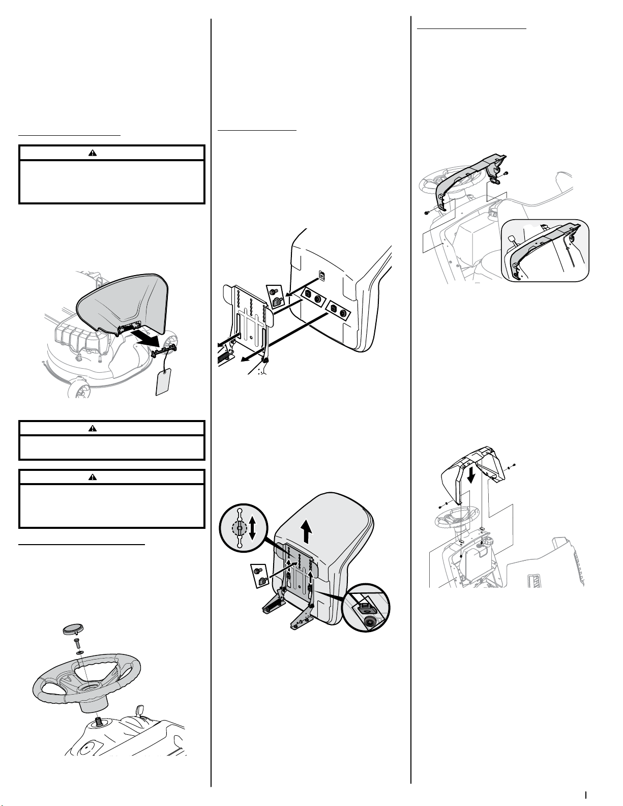
Dash Shroud (If Equipped)
There are two shroud types. One shroud for the
1/3/5/K/T-Style and one for the S-Style dash.
Continue below for the 1/3/5/K/T-Style, skip ahead to
the S-style section for the S-style dash.
1/3/5/K/T-Style Dash
1. If the dash shroud (a) was shipped loose, the
hardware for attaching the dash shroud (a) is
shipped installed in the dash (c). Remove the two
bolts (b) from the dash (c) . See Figure 2-7.
(b)
(a)
(c)
(a)
(b)
Figure 2-7
2. Mount the dash shroud (a) and align the
mounting holes. See Figure 2-7.
3. Secure the dash shroud (a) to the dash (c) with
the bolts (b) removed in Step 1. See Figure 2-7.
S-Style Dash
1. If the dash shroud (a) was shipped loose, the
hardware for attaching the dash shroud (a) is
shipped installed in the dash shroud (a) and the
dash (b). Remove the two bolts (c) and washers
(d) from the dash (g) and two bolts (e) and clips (f)
from the dash shroud (b). See Figure 2-8.
(g)
(b)
(a)
(c)
(c)
(d)
(d)
(e)
(e)
(f)
(f)
Figure 2-8
2. Mount the dash shroud (a) and align the
mounting holes. Using the bolts (c/e), washers
(d) and clips (f) install the dash shroud (a) and
snug the bolts (c) so that the dash shroud (a)
can be adjusted.
Close the hood and align the dash shroud (a) to
the hood (g) leaving a uniform gap between the
hood (g) and the dash shroud (a).
3. Raise the hood (g) and tighten the bolts (c/e) that
hold the dash shroud (a) on the dash (b).
Loading ...
Loading ...
Loading ...