Loading ...
Loading ...
Loading ...
17
3. Drill holes at A and B, if the Wall studs are not located A and B
hole, do not drill A and B hole, and follow the below
instruction.
In addition to being installed on at least 1 wall stud, the
mounting plate must attach to the wall at both end holes. If the
end holes are not over wall studs, use two 3/16-24 x 3" round
head bolts with toggle nuts; if 1 end hole is over a wall stud,
use 1 lag screw and one 3/16-24 x 3" round-head bolt with
toggle nut; or if both end holes are over wall studs, use 2 lag
screws. Following are 3 installation configurations.
Installation for No Wall Studs at End Holes
(Figures 1 and 2 in Find the Wall Stud(s) section)
1. Drill 5/8" (1.6 cm) holes through the wall at both end holes
marked in Step 3 of the “Mark Rear Wall.”
2. Drill 3/16" (5 mm) hole(s) into the wall stud(s) at the
hole(s) marked in step 6 of the “Mark Rear Wall.” Refer to
figures 1 and 2 in “Possible Wall Stud Configurations” in
the “Locate Wall Studs(s)” section.
Installation for Wall Stud at One End Hole
(Figure 3 in Find the Wall Stud(s) section)
1. Drill a 3/16" (5 mm) hole into the wall stud at the end hole
marked in Step 3 of the “Mark Rear Wall.”
2. If installing on a second wall stud, drill a 3/16" (5 mm) hole
into the wall stud at the other hole marked in Step 6 of the
“Mark Rear Wall.” Refer to Figure 3 in “Possible Wall Stud
Configurations” in the “Locate all Stud(s)” section.
3. Drill a 5/8" (1.6 cm) hole through the wall at the other end.
Installation for Wall Studs at Both End Holes
(Figure 4 in Find the Wall Stud(s) section)
1. Drill 3/16" (5 mm) holes into the studs at the end holes
marked in Step 3 of the “Mark Rear Wall.”
4. Using a keyhole saw, cut out the rectangular wall venting
cutout area. Skip this step if for recirculation venting or roof
venting installation.
A
A. Wall Venting Cutout Area
Attach Mounting Plate to Wall
1. Position mounting plate on the wall.
NOTE: It may be necessary to use a number of the spacers,
between the mounting plate and the wall, to achieve a more
‘Flush’ appearance. Stick spacers before position mounting
plate on the wall.
Measure from the back wall to where the front bottom surface
of the microwave oven needs to be to determine the number
of spacers needed.
B
A
A. Mounting Plate
B. 1/16" (1.6 mm) thickness
Depth of cabinet Mounting plate
12" to 13"
(30.5 cm to 33 cm)
Mounting plate
13
1
/
16
" (33.2 cm) Mounting plate + 4 pieces of
spacer
13
1
/
8
" (33.3 cm) Mounting plate + 8 pieces of
spacer
2. Secure the mounting plate to the wall at both end holes drilled
into the wall studs and/or drywall using either 3/16-24 x 3"
round-head bolts and toggle nuts or 1/4 x 2" lag screws.
Refer to illustrations in “Possible Wall Stud Configurations” in
the “Locate Wall Stud(s)” section, and the following sections
“No Wall Studs at End Holes (Figures 1 and 2 in Find the Wall
Stud(s) section)” or “ Wall Stud at One End Hole (Figure 3 in
Find the wall Stud(s) section)” .
3. Insert lag screws into both end holes.
4. Check alignment of mounting plate, making sure it is level.
5. Secure the two end hole screws.
No Wall Studs at End Holes (Figures 1 and 2 in
Find the Wall Stud(s) section)
NOTE: The mounting plate must be secured to the wall on at
least 1 wall stud as well as at both ends.
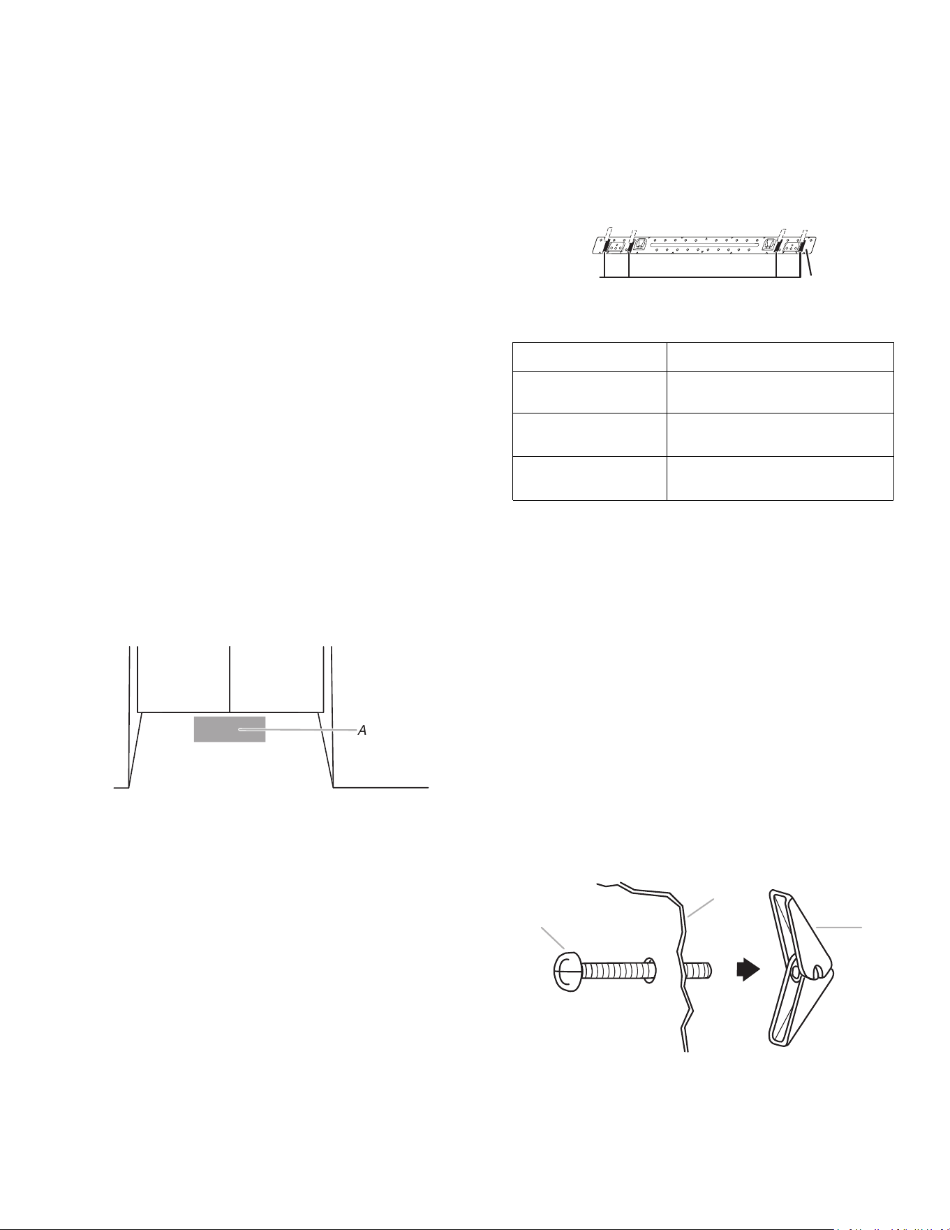
1. With the support tabs of the mounting plate facing forward,
insert 3/16-24 x 3" round-head bolts through both end holes of
mounting plate.
2. Start toggle nuts on bolts from the back of the mounting plate.
Leave enough space for the toggle nuts to go through the wall
and to open.
A
B
C
A. 3/16-24 x 3" round-head bolt
B. Mounting plate
C. Spring toggle nut
3. Position mounting plate on the wall.
Loading ...
Loading ...
Loading ...