Loading ...
Loading ...
Loading ...
16
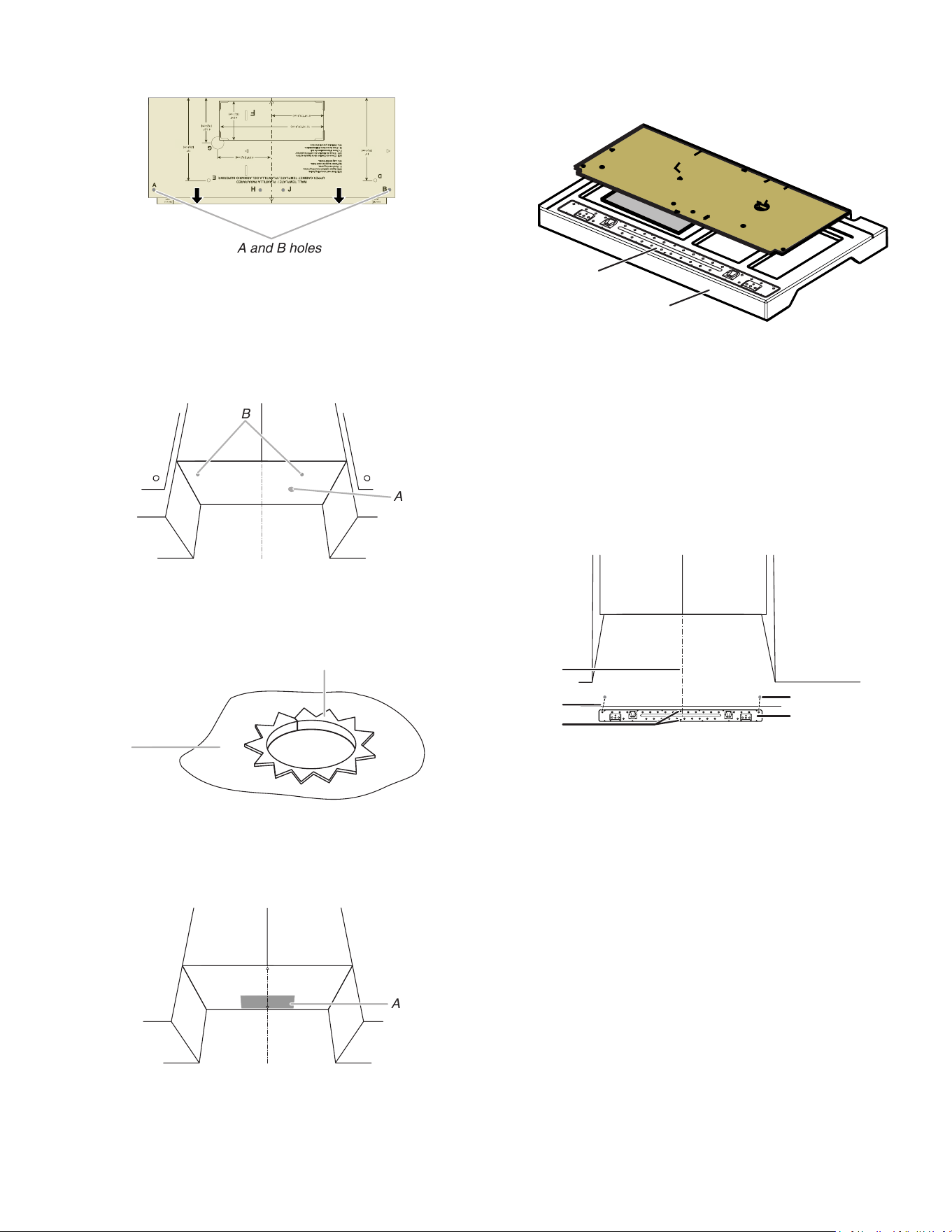
6. Draw A and B two small circles, H and J is not necessary,
depending on your need.
A and B holes
Drill holes in Upper Cabinet
1. Using a drill and the 0.75" (1.9 cm) hole saw, cut out the
power cord hole (A).
2. Drill two mounting nut holes (B), which are 3/8" (10 mm) holes
at points “D” and “E” on the cardboard template. These are for
two 1/4-20 x 3" bolts and washers used to secure the
microwave oven to the upper cabinet.
A
B
A. Power Cord Hole
B. Mounting Nut Holes
NOTE: If upper cabinet is metal, the supply cord bushing
needs to be installed around the supply cord hole as shown.
A
B
A. Metal cabinet
B. Power supply cord bushing
3. Using a keyhole saw, cut out the rectangular roof venting
cutout area. Skip this step if for recirculation venting or wall
venting installation.
A
A. Roof Venting Cutout Area
Drill holes in Rear Wall
1. The mounting plate is located inside the outer foam in the
cavity, take it out.
B
A
A. Mounting Plate
B. Outer Foam in the Carton
2. Attach the mounting plate to wall. Make sure the 2 holes on
mounting plate align with the A and B holes marked in the
“Mark Rear wall” section and the mounting plate center
markers align with the Center Mark.
NOTE: It may be necessary to use a number of the spacers,
between the mounting plate and the wall, to achieve a more
‘Flush’ appearance. See “Attach Mounting Plate to Wall”
section for more details.
Measure from the back wall to where the front bottom surface
of the microwave oven needs to determine the number of
spacers needed.
A
B
C
D
E
A. Mounting Plate
B. A and B holes
C. Mounting Plate Bottom Line
D. Center Mark
E. Mounting plate center markers
Loading ...
Loading ...
Loading ...