This manual is intended for the users of the DA-FM1500 ceiling mounting
bracket. It includes the instructions for mounting the DA-FM1500 ceiling
mounting bracket to the ceiling.
• This bracket is intended to be used with some models of dome
cameras. Ask your retailer for details on a specic model and do
not use it with other models of cameras.
• This installation should be performed by a qualied service
personnel in conformance to all local codes.
• You may need to reinforce the ceiling. If the ceiling is not strong
enough to support the camera, the camera may fall.
• Do not use this product for other purposes.
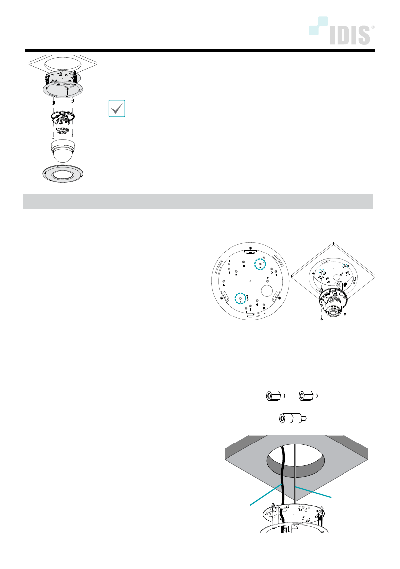
Mounting
1
Assemble the camera body to the bracket by
tightening the screws.
• DC-D3233WRX / DC-D3233RX / DC-D3233X Models:
Screw No. 5 (3-point), PCB Support 8.8mm
• DC-D4233WRX / DC-D4233HRX / DC-D4223WRX
DC-D4236WRX / DC-D4236HRX / DC-D4533HRX
DC-D4536HRX / DC-D4831HRX / TC-D5531WRX(P)(-A)
Models: Screw No. 5 (3-point), PCB Support 8.8mm 6ea
• DC-D4233RX / DC-D4223RX / DC-D4533RX /
DC-D4536RX / TC-D5531RX(P)(-A) Models: Screw No. 4
(2-point), PCB Support 8.8mm 4ea
• TC-D4222WRX / TC-D4221WRXP Model: Screw
No. 6 (2-point), No PCB support necessary
• TC-D4222RX / TC-D4221RXP Model: Screw
No. 6 (2-point), PCB Support 8.8mm
• DC-D4236(R)X Model: Screw No. 2 (3-point), PCB
Support 8.8mm 6ea
• Other Vandal Dome Models: Screw No. 1 (3-point), No
PCB support necessary
< Screw No. >
(DC-D4233RX Model)
*When using the screws of DC-D4233RX / DC-D4223RX
/ DC-D4236(R)X / DC-D4533RX /TC-D5531RX(P)(-A)/
DC-D4233WRX / DC-D4233HRX / DC-D4223WRX / DC-
D4236WRX / DC-D4236HRX /
DC-D4533HRX / DC-D4831HRX / TC-D5531WRX(P)(-A)
models, combine the two as shown below.
2
Connect the cable through the cable hole and
screw the safety wire to the bracket to prevent
the bracket from falling on to the oor.
Cable
Safety Wire
DA-FM1500 INSTALLATION MANUAL
IDIS Co., Ltd.
For more information, please visit www.idisglobal.com
Ver.1.0
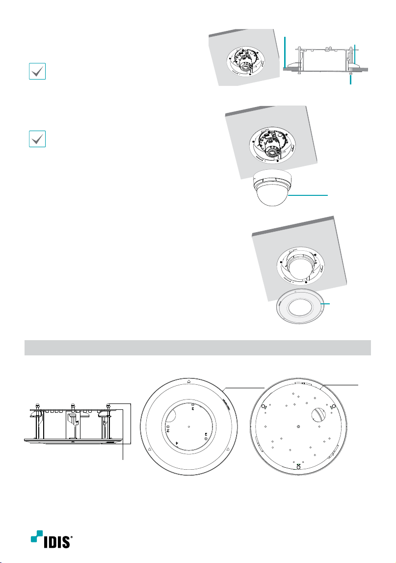
3
Mount the bracket to the ceiling, then x it
with the clamp (3-point) by turning the clamp
screws clockwise. And adjust the angle.
Adjust the tilt angle not to cause IR
reection.
Clamp
Ceiling
Clamp Screw
(3-Point)
4
Assemble the dome cover to the camera body.
Make sure that Silicon or EVA cushion is
assembled and rmly pressed against the
camera dome cover, otherwise it will create
IR rection.
Dome Cover
5
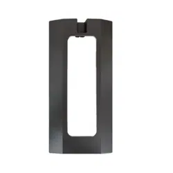
Assemble the bracket lid to the bracket.
Bracket Lid
Dimensions
Unit: mm (inch)
87 (3.43)
63.7 (2.51) 10.3
(0.41)
Ø 210.2 (8.28)
Ø 185 (7.28)