
Loading ...
Loading ...
Loading ...
5
•
WARNING
Some dust created by power sand-
ing, sawing, grinding, drilling, and
other construction activities contains chemicals
known to cause cancer, birth defects or other repro-
ductive harm. Some examples of these chemicals
are:
• lead from lead-based paint
• crystalline silica from bricks and cement and other
masonry products, and
• arsenic and chromium from chemically-treated
lumber.
Your risk from these exposures varies, depending
on how often you do this type of work. To reduce
your exposure to these chemicals: work in a well
ventilated area, and work with approved safety
equipment, such as those dust masks that are spe-
cially designed to lter out microscopic particles.
SPECIFICATIONS
Cat. No. ..................................................... 2984-20
Volts.............................................................. 18 DC
Battery Type .................................................M18™
Charger Type................................................M18™
Rated RPM ...................................................20,000
Max Wheel Ø ....................................................... 2"
Max Sanding Accessory Ø .................................. 3"
Module/FCC ID ............................ BGM11S/QOQ11
Recommended Ambient
Operating Temperature .................... 0°F to 125°F
SYMBOLOGY
Volts
Direct Current
Rated Revolutions per Minute (RPM)
Read Operator's Manual
RAPIDSTOP™ Electric Braking
C
US
UL Listing for Canada and U.S.
FUNCTIONAL DESCRIPTION
1. Collet nut
2. Front grip
3. Spindle lock
4. Rear grip
5. Dust screen
6. Speed dial
7. ONE-KEY™ indicator
8. Switch lock-o
9. Paddle switch
10. 11/16" wrench (not shown)
1
2
3
8
4
5
7
9
6
ASSEMBLY
WARNING
Recharge only with the charger
specied for the battery. For spe-
cic charging instructions, read the operator’s
manual supplied with your charger and battery.
Removing/Inserting the Battery
To remove the battery, push in the release buttons
and pull the battery pack away from the tool.
WARNING
Always lock the trigger or remove
the battery pack any time the tool
is not in use.
To insert the battery, slide the pack into the body
of the tool. Make sure it latches securely into place.
WARNING
Only use accessories specically
recommended for this tool. Others
may be hazardous.
Installing Collets
The collet must be attached to the collet nut before
installing the collet assembly to the tool. Be sure that
the collet size matches the size of the mandrel you
will use, otherwise the collet may break.
1. To assemble, place collet on an even surface, and
place the nut over the collet.
2. Press down on the nut to snap the nut and collet
together.
3. To disassemble, use a rod to push the collet out
of the nut.
WARNING
To reduce the risk of injury, always
securely tighten the collet to the
grinders and clean mandrels before inserting
them into the collet. Otherwise the high-speed
rotation of the tool could force the accessory to
y out of the collet.
Installing Accessories
1. Remove dust and debris from the collet body
before inserting accessory.
2. Insert the collet with the collet nut attached into the
collet body. Thread the collet nut onto the spindle
but do not tighten it yet.
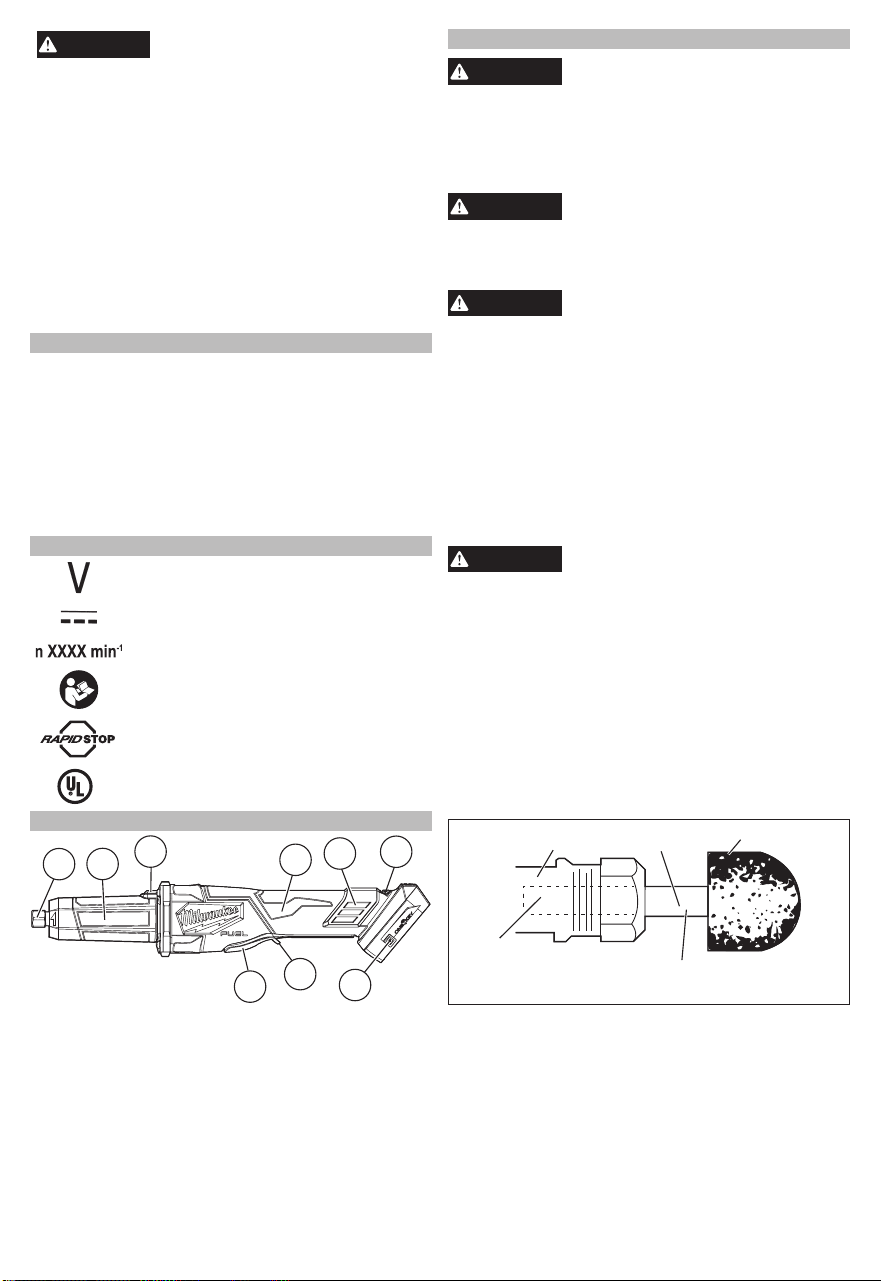
3. Clean the accessory mandrel, then insert it a
minimum of 1" into the collet. The mandrel will
overhang the collet and the accessory about 1/2".
Insert mandrel
a minimum of 1"
inside the collet
Overhang about 1/2"
Accessory
Mandrel
Collet
4. Press in the spindle lock button while turning the
collet nut clockwise. Tighten securely.
5. Reverse the procedure when removing the acces-
sory.
Loading ...
Loading ...
Loading ...