305MM 3-IN-1 SHEET METAL MACHINE
MODEL NO: TIO305
Thank you for purchasing a Sealey product. Manufactured to a high standard, this product will, if used according to these
instructions, and properly maintained, give you years of trouble free performance.
IMPORTANT: PLEASE READ THESE INSTRUCTIONS CAREFULLY. NOTE THE SAFE OPERATIONAL REQUIREMENTS, WARNINGS & CAUTIONS. USE
THE PRODUCT CORRECTLY AND WITH CARE FOR THE PURPOSE FOR WHICH IT IS INTENDED. FAILURE TO DO SO MAY CAUSE DAMAGE AND/OR
PERSONAL INJURY AND WILL INVALIDATE THE WARRANTY. KEEP THESE INSTRUCTIONS SAFE FOR FUTURE USE.
1. SAFETY
9 Wearapprovedsafetygoggles,gloves,andfootwear,whenoperatingthefolder.YourlocalSealeystockistoersacompleterangeof
safetyequipment.
9 Use the tool only for its intended purpose.
9 Regularlycheckallpartsofthefolderfordamagedparts.DO NOTuseifanyofitscomponentsarebroken,wornordamaged.
9 UseoriginalSealeysparepartsandaccessories.Useofnon-recommendedsparepartsmaybedangerousandwillinvalidate
warranty.
9 Ensure good footing, wear non slip footwear.
8 DO NOToperatethistoolwhileundertheinuenceofdrugs,alcoholorotherimpairingmedication.
8 DO NOTAllowunqualiedpersonstooperatethemetalfolder.Keepchildrenawayfromthetool.
9 Beawareofsharpedgesorsharpshredsofmetalthatmaybecreated.Useheavydutygloveswhenhandlingtheworkpiece.
2. INTRODUCTION
12”3-in-1lightsheetmetalworkingmachine.Canshear,bendandrollavarietyofmetalsincludingmildsteel,aluminiumandcopper.The
rollershavegrooveswithdiametersof2.5mm,3mm,4mm,5mm,5.5mmand6mmforbendingrods.Adjustthedistanceandangleofthe
rollerstocreatethedesiredcurvatureforcurves,cylindersorcones.Shearsheetsofmetalupto305mmwide.Makepanswithamaximumlip
of1”andbend(brake)sheetsuptoanangleof90°.
3. SPECIFICATION
Model No:..................................................................................................TIO305
Die Sizes: ................................... 25mm/1”,50mm/2”x2,76mm/3”and102mm/4”
MinimumRollerDiameter: ..................................................................38mm/1-1/2”
TubeRollingDiameter: .....................2.5mm,3mm,4mm,5mm,5.5mmand6mm
WorkpieceMaximumThickness:
Mild Steel: ...................................................................................... 1mm/20gauge
Aluminiumandcopper: ............................................................... 1.2mm/18gauge
WorkpieceMaximumWidth: .................................................................305mm/12”
4. SET UP
4.1. REMOVAL AND ADJUSTMENT OF HANDLE
4.1.1. TheHandle(18#)maybeadjustedormovedbyremovingoneoftheHandleKnobs(26#)andlooseningtheClampBolt(60#)that
holdsthehandleinplace.Itmaythenbeslidoutofthehandlesocket,movedtotheoppositesideofthetool,andtightenedinthe
mostconvenientposition.
4.2. REMOVAL AND ADJUSTMENT OF FINGERS
4.2.1. TheFingers(12#)issegmentedandcanbeusedforvarying
sizesofboxandpanforming.Whenformingasmallerboxor
pan,choosethedesiredsizenger,centreitandremovethe
others.Seebelowforadjustmentinstructions.
4.2.2. TheShearBrakeRollcanbeusedtobendsheetmetalupto
20Gauge.ThespacebetweentheFingers(12#)andthe
MovingCutterPlate(11#)isadjustable.
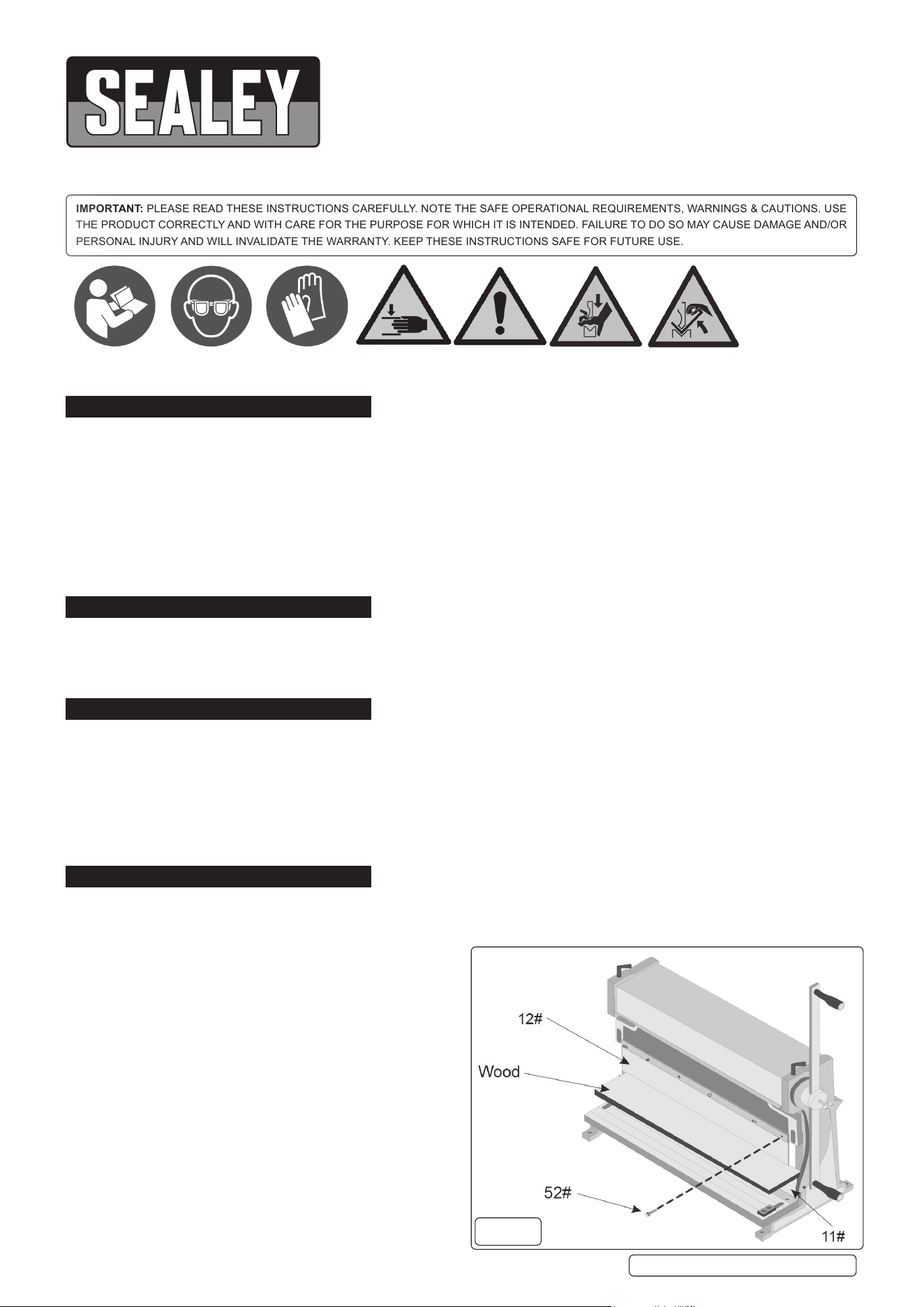
4.2.2.1. Toadjustthespacing,performthefollowingsteps:Placea
atstraightpieceofwoodbetweentheFingers(12#)and
MovingCutterPlate(11#)andraisetheMovingCutterPlate
(11#)sothatthematerialjusttouchestheFingers(12#)as
showninFig.1.
4.2.2.2. LoosentheScrews(52#)holdingtheFingers(12#)inplace.
Itisnotnecessarytoremovethem.
4.2.2.3. RemoveanyunneededFingers(12#).
4.2.2.4. RaiseandlowertheMovingCutterPlate(11#)andusethe
blockofwoodtoadjustthealignmentoftheFingers(12#).
g.1
TIO305Issue109/03/2021
Original Language Version
©JackSealeyLimited
Refer to
instructions
Wear eye
protection
Wear protective
gloves
Danger Moving
machineryriskof
crushed hands
Danger Moving
Machinery risk
oftrappedhand/
ngers
WARNING;
Handcrushing
betweenpress
braketool
WARNING;
Handcrushing
betweenpress
brakeand
material
TightentheScrews(52#).
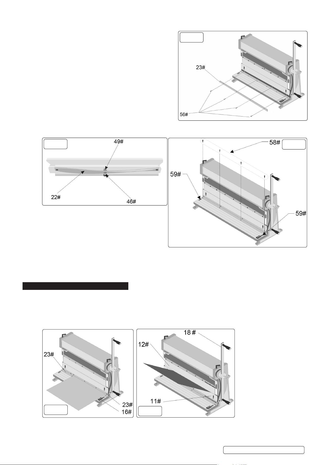
4.3. REMOVAL AND INSTALLATION OF UPPER CUTTING BLADE
4.3.1. RemovetheScrews(56#)fromtheuppercuttingBlade(23#)as
showninFig.2.
4.3.2. RemovetheuppercuttingBlade(23#).
4.3.3. AlignuppercuttingBlade(23#)MovingCutterPlate(11#)and
secure with its Screws.
4.4. ADJUSTMENT OF UPPER BLADE
4.4.1. Placea12”pieceofthincardboardorpaperbetweentheupperand
lowerBlades(23#).
4.4.2. RotatetheHandle(18#)andcutthematerial.
4.4.3. Useastraightedgetodeterminethestraightnessofthecutandif
theBladeisinneedofadjustment.
4.4.4. IftheuppercuttingBlade(23#)isbowedout,awayfromthefrontof
thetool,turntheadjustmentNut(49#)counter-clockwiseasshown
inFig.3.ThiswilltightentheSupportingPlate(22#)andpushthe
middleoftheuppercuttingBlade(23#)outwhilepullingitsendsin.
4.4.5. IftheuppercuttingBlade(23#)isbowedin,towardsthebackofthe
tool,turntheadjustmentNut(49#)clockwiseasshowninFig.3.ThiswillloosentheSupportingPlate(22#)andpullthemiddleof
theuppercuttingBlade(23#)inwhilepushingitsendsout.
4.5. REMOVAL AND INSTALLATION OF LOWER BLADE
4.5.1. RemovetheScrews(58#)fromthelowercuttingBlade(23#)
asshowninFig.4.
4.5.2. RemovethelowercuttingBlade(23#).
4.5.3. ReplacethelowercuttingBlade(23#)andsecureusingitsHex
Screws.
4.6. ADJUSTMENT OF LOWER CUTTING BLADE
4.6.1. LowertheupperBlade(23#)toitslowestposition.
4.6.2. LoosenthetwoScrews(59#)locatedontopoftheWorkBench(2#)asshowninFig.4.
4.6.3. AdjustthelowercuttingBlade(23#)byturningScrews(17#)asshowninthePartsDiagram.Thedistancebetweenthelower
cuttingBlade(23#)andtheUpperCuttingBlade(23#)shouldbe5to8percentofthethicknessoftheworkpiece.
4.6.4. TightenthetwoScrews(59#)locatedontopoftheWorkBench(2#).
5. OPERATION
5.1. SHEARING
5.1.1. Scribethecuttingmarkonthematerial.
5.1.2. SlidethematerialbetweentheUpperBlade(23#)andtheLowerBlade(23#)sothattheUpperBladeispositioneddirectlyabove
themarkandtherighthandsideofthematerialrestsagainsttheGuide(16#),asshowninFig.5.
NOTE: GuidemustbeonthissideoftoolasshowninFig.5.
5.1.3. Whileholdingthematerialsteady,rotatetheHandleuntilthematerialhasbeencut.
5.2. ANGLE BENDING
5.2.1. Marktheworkpiecewhereyouwanttobendthematerial.
5.2.2. PlacematerialabovetheMovingCutterPlate(11#)asshowninFig.6.
5.2.3. AlignthebendingmarkwiththefrontedgeoftheFingers(12#).
g.2
g.3
g.4
g.5
g.6
TIO305Issue109/03/2021
Original Language Version
©JackSealeyLimited
5.2.4. RotatetheHandle(18#)untilthedesiredanglehasbeenformed.Useaprotractororothermeasuringtooltoensureaccuracy.
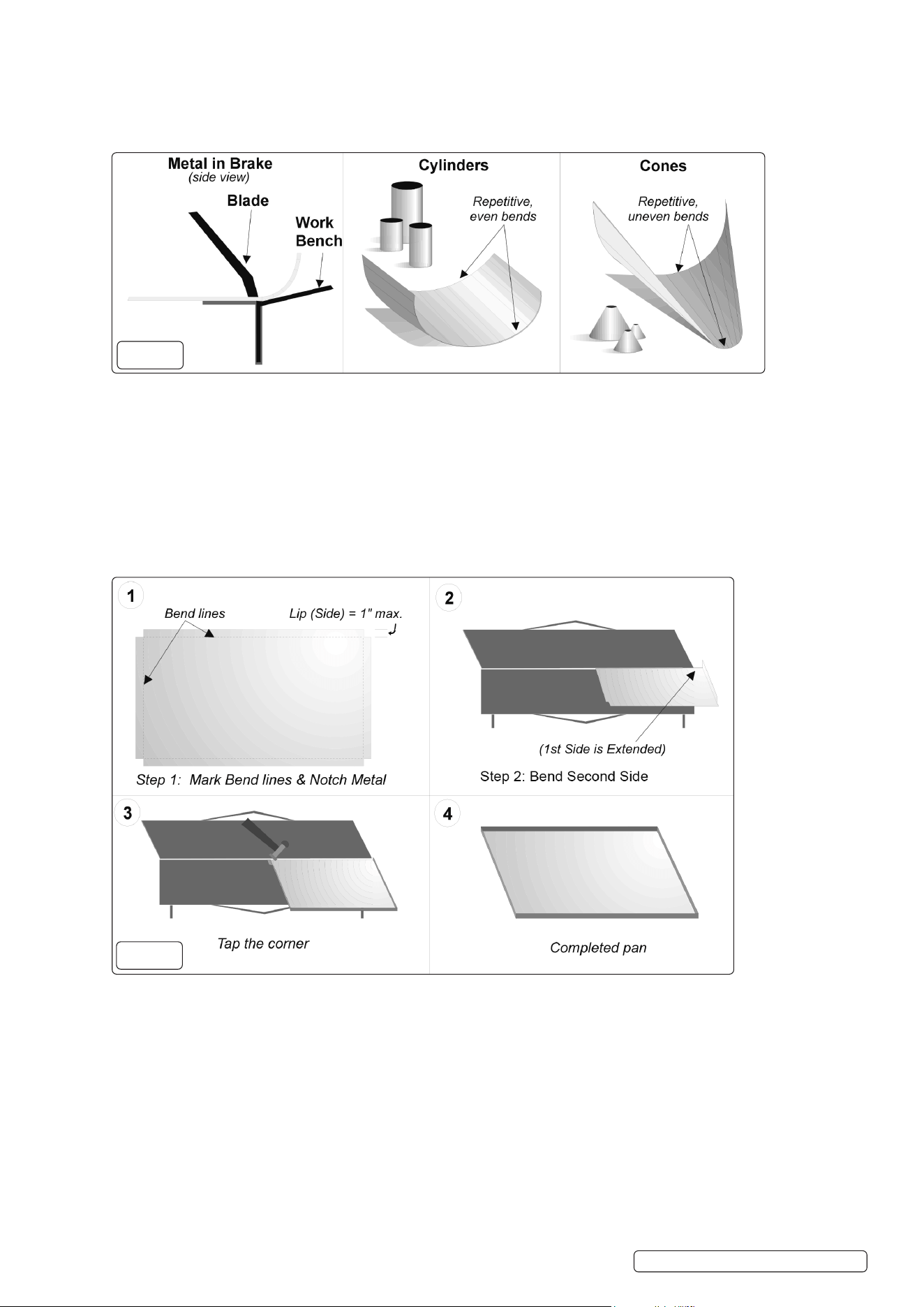
5.3. RADIUS BENDING
5.3.1. Radiusbendingismostcommonlyusedtomakecylindersandcones,asshowninFig.7.
5.3.2. Bothshapesareformedbymakingaseriesofsmall,closelyspacedbendsintheworkpiece.
5.3.3. Forcylinders,thebendsareevenlyspaced,i.e.everybendisidentical.
5.3.4. ForCones,simplymoveonesideofyourstockoutfurtherthantheothereverytimeyoumakeabend.
5.4. PAN FORMING
NOTE: TheHandBrakeRollcanbeusedtomakevarioussizesofpans.Themaximumlip(side)heightsupportedbythistoolis1”.
5.4.1. Pre-measureandcutyourmaterialbeforebending.NotchthecornersaccordingtothedesiredlipheightasshowninFig.8.
5.4.2. InsertmaterialbetweentheFingers(12#)andtheMovingCutterPlate(11#).Bendthematerialuntilas90ºdegreeanglehasbeen
formed.
5.4.3. Rotatethematerial90ºcounterclockwise.Allowthecompletedsidetoextendjustbeyondthetooling.Bendthesecondside.
5.4.4. Repeat5.4.3forthethirdside.
5.4.5. Rotatetothenalside,andinsertworkpiecebetweenthetooling.Yourformedsideswillbeontheoutsideofthetooling.
5.4.6. Beforebending,taponecornernearertothemiddleofthemachine.ThiswillallowthematerialtocleartheFingers(12#)when
raised.
5.4.7. Bend the fourth side.
5.4.8. Usingablockorpieceofwood,tapthecornerofmaterialbackintoplace.
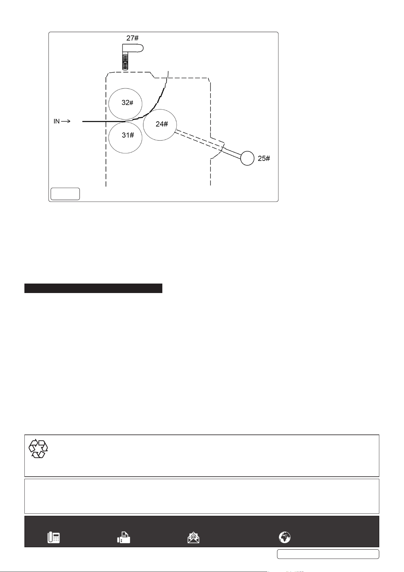
5.5. ROLLING
5.5.1. MovetheCover(33#)backandoutoftheway.
5.5.2. DroptheBackPressingRoll(24#)bylooseningtheRollerAdjustmentwithKnob(25#).
5.5.3. InsertjusttheleadingedgeofyourworkpiecebetweentheUpperPressingRoll(32#)andLowerPressingRoll(31#),andtighten
therollbargapAdjustableScrew(27#)untiltheRollBarsarebarelysnugagainsttheworkpiece.
5.5.4. AdvancetheRollerAdjustmentWithKnob(25#)asmuchasdesireddependinguponthetightnessoftherolltobeaccomplish.
(Thetightertheroll,themoretheknobsmustbeadvanced.)
5.5.5. CranktheHandleAssembly(18#and26#)untiltheproperrollhasbeenachieved.Thematerialshouldfeeditselfthroughthe
rollersasyoucranktheHandleAssembly.
5.6. WIRE ROLLING
5.6.1. UsethepropergrooveintheUpperPressingRoll(32#)dependingupontheGaugeofthewirebeingrolled.
5.6.2. Followtheproceduresaslistedabovein“Rolling”.
5.7. PRESSING
5.7.1. SlidethePressPlateBrackets(8#)ofthePressPlateAssemblyintothereceiverholesoftheMovingCutterPlate(11#).Notethat
thePressingPlate(10#)shouldbefacingdown.
5.7.2. PlacetheworkpiecesothatitiscentredunderthePressingPlate(10#).
g.7
g.8
TIO305Issue09/03/2021
Original Language Version
©JackSealeyLimited
5.7.3. RotatetheHandle(18#)topresstheworkpiece.
5.8. SHEET METAL & WIRE FORMING
5.8.1. RemovetheCover(33#)fromthemachine.TherollerGears(30#)shouldhaveacoatingofgeneralpurposegreaseforsmooth
operation.Cleananydirtorexcessgreasefromtherolls.
5.8.2. Thefollowingstepsapplytobothwireandsheetmetalbending.
5.8.3. AdjustScrews(27#)tothethicknessofthestock.Itshouldfeedbetweenrollers(31#)and(32#)withoutslippingorbindingwhen
thehandle(18#)isturned.Thematerialisfedintotherollersfromthefrontofthemachine.
5.8.4. BackPressingRoll(24#)formstheradiusinthematerial.Thecloseritistothefeedrollers,thesmallertheradiuswillbe.Roller
AdjustmentWithKnob(25#)adjuststhespacingofthebackroller.
5.8.5. Metalswillhavedierentbendingcharacteristics.Someareverypliable,whileothershaveconsiderablespringormemory.Practice
beforebeginninganimportantproject.
6. MAINTENANCE
6.1. LubricatetherotatingPartsofthemachineeveryday.Thiscanlengthenthemachinelife.
g.9
Sealey Group, Kempson Way, Suffolk Business Park, Bury St Edmunds, Suffolk. IP32 7AR
01284 757500 01284 703534 sales@sealey.co.uk www.sealey.co.uk
ENVIRONMENT PROTECTION
Recycleunwantedmaterialsinsteadofdisposingofthemaswaste.Alltools,accessoriesandpackagingshouldbesorted,takento
arecyclingcentreanddisposedofinamannerwhichiscompatiblewiththeenvironment.Whentheproductbecomescompletely
unserviceableandrequiresdisposal,drainanyfluids(ifapplicable)intoapprovedcontainersanddisposeoftheproductandfluids
according to local regulations.
Note:Itisourpolicytocontinuallyimproveproductsandassuchwereservetherighttoalterdata,specificationsandcomponentpartswithoutprior
notice.
Important:NoLiabilityisacceptedforincorrectuseofthisproduct.
Warranty:Guaranteeis12monthsfrompurchasedate,proofofwhichisrequiredforanyclaim.
TIO305Issue109/03/2021
Original Language Version
©JackSealeyLimited