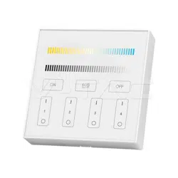
WALL PANEL REMOTE - 4 ZONE
INTRODUCTION & WARRANTY
FUNCTION OF KEYS
PARTS OF DESCRIPTION
CONTROLLER FUNCTIONS
Thank you for selecting and buying V-TAC product. V-TAC will serve you the best. Please read these instructions
carefully before starting the installation and keep this manual handy for future reference. If you have any
another query, please contact our dealer or local vendor from whom you have purchased the product. They are
trained and ready to serve you at the best. The warranty is valid for 2 years from the date of purchase. The
warranty does not apply to damage caused by incorrect installation or abnormal wear and tear. The company
gives no warranty against damage to any surface due to incorrect removal and installation of the product. The
products are suitable for 10-12 Hours Daily operation. Usage of product for 24 Hours a day would void the
warranty. This product is warranted for manufacturing defects only.
IN CASE OF ANY QUERY/ISSUE WITH THE PRODUCT, PLEASE REACH OUT TO US AT: SUPPORT@V-TAC.EU
FOR MORE PRODUCTS RANGE, INQUIRY PLEASE CONTACT OUR DISTRIBUTOR OR NEAREST
DEALERS. V-TAC EUROPE LTD. BULGARIA, PLOVDIV 4000, BUL.L.KARAVELOW 9B
WARNING!
1. Please make sure to turn off the power before starting the installation.
2. Installation should only be done by a certified electrician.
3. For Indoor use only
4. Please check the cable, and make the circut is correct before power on.
5. Please do not use lighting fixtures around the mental area and high magnetic field, otherwise, it will badly
affect the control distance.
Caution, risk of electric shock.
This marking indicates that this
product should not be disposed
of with other household wastes.
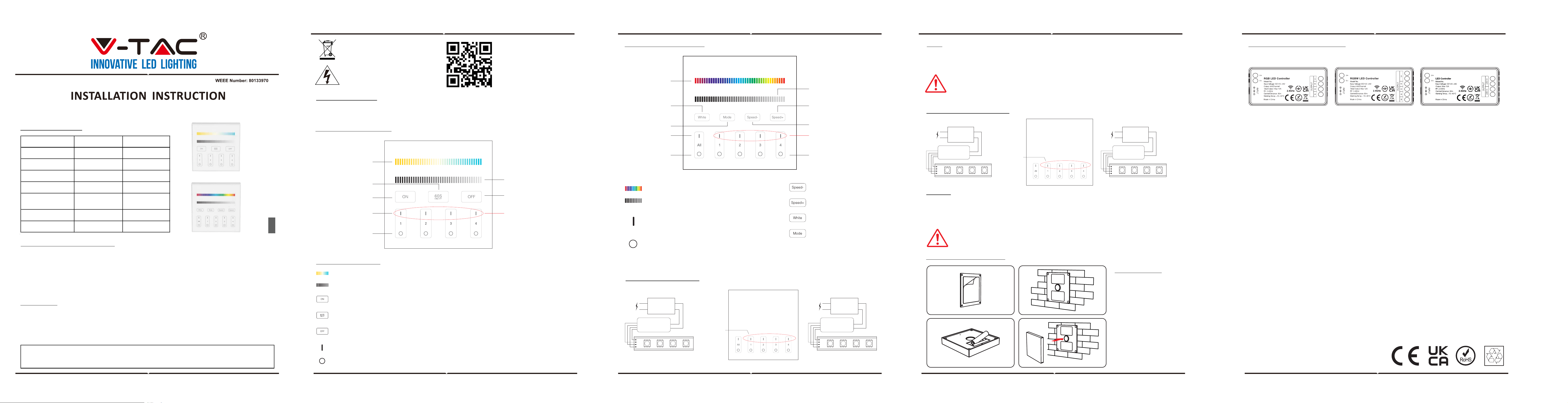
TECHNICAL DATA:
2
YEARS
WARRANTY
*
MODEL VT-2437
INPUT VOLTAGE
3V(2*AAA BATTERY)
(Ba�ery not included)
MODULATION METHOD
GFSK
TRANSMITTING POWER 6dBm
STANDBY POWER
20μA
OPERATION
TEMPERATURE
-10°C to +40°C
CONTROL DISTANCE
30m
DIMENSION
86x86mm
VT-2439
3V(2*AAA BATTERY)
(Ba�ery not included)
GFSK
6dBm
20μA
-10°C to +40°C
30m
86x86mm
BUTTON FUNCTIONS
Remark: When touching the button, LED indicating lamp will flash once with different sound
(Touch slider with no sound).
Zone ON
Zone OFF
ALL OFF
4x(un) Link Light
Dimming Slider
60S Delay OFF
ALL ON
CCT Slider
Touch the slider to change color temperature.
Touch dimming slider to change the brightness from 1~100%.
Touch master ON, turn on all linked lights.
Long press 5 seconds to turn ON the indicating sound.
When the light is ON, press “60S Delay OFF”, the light will be OFF.
Automatically after 60 seconds.
Touch master OFF, turn off all linked lights.
Long press 5 seconds to turn OFF the indicating sound.
Touch Zone ON, turn on zone-linked lights.
Touch Zone OFF, turn off zone-linked lights.
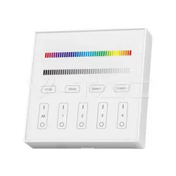
ALL ON
Mode Speed +
Mode Speed -
Zone ON & 4x(un)
Link Light
Zone OFF
ALL OFF
Dimming Slider
White
Mode
Color Slider
Touch white button to
white light mode.
Switching modes.
Touch dimming slider to change the brightness from
1~100%.
Touch color slider, choose the color you want.
Slow the speed on present
dynamic mode.
Accelerate the speed on
present dynamic mode.
ALL ON: Touch to turn on all linked lights.
Long press 5 seconds to turn ON the indicating sound.
Zone(1-4) ON: Touch zone ON, turn on zone-linked lights.
ALL OFF: Touch to turn off all linked lights.
Long press 5 seconds to turn OFF the indicating sound.
Zone(1-4) OFF: Touch zone OFF, turn off zone-linked lights.
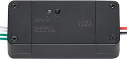
LINKING INSTRUCTION
UNLINKING INSTRUCTION
Link/Unlink
bu�on
B
+
G
R
Power
Supply
controller
B
+
G
R
Power
Supply
controller
LINK
• Switch off the light, after 10 seconds switch on again.
• When the light on, short press any zone of " " 3 times within 3 seconds.
• The light blink 3 times slowly means the linking is done successfully.
• Switch off the light, after 10 seconds switch on again.
• Switch off the light, after 10 seconds switch on again. Unlinking must be the same zone
with the Linking
• The light blinking 10 times quickly, means the unlinking successfully.
UNLINK
INSTALLATION
INSTALLATION DIAGRAM
If the light not blink slowly, the linking failed, please switch off the light again,
and follow the above steps again.
If the light not blink quickly, the unlink failed, pls switch off the light again,
and follow the above steps to unlink again.
Link/Unlink
bu�on
B
+
G
R
Power
Supply
controller
B
+
G
R
Power
Supply
controller
1. Tear out the back tape.
2. Stick the holder on the
position where you want.
3. Install 2*AAA battery.
4. Put the rotating switch
on the front of holder.
(VT-2439)
(VT-2437)
MULTI-LANGUAGE
MANUAL QR CODE
Please scan the QR code
to access the manual in
multiple languages.
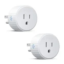
LINKING/UNLINKING DEVICES
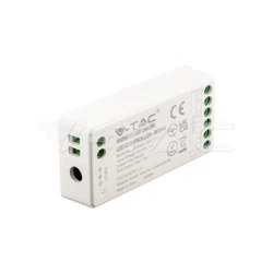
Compatible with the below devices (Not included; available to buy separately)
(SKU: 2912
VT-2432)
(NOT INCLUDED)
(SKU: 2911
VT-2431)
(NOT INCLUDED)
(SKU: 2913
VT-2434)
(NOT INCLUDED)
VT-2432
VT-2434
VT-2431