Loading ...
Loading ...
Loading ...
2323
For the Installer
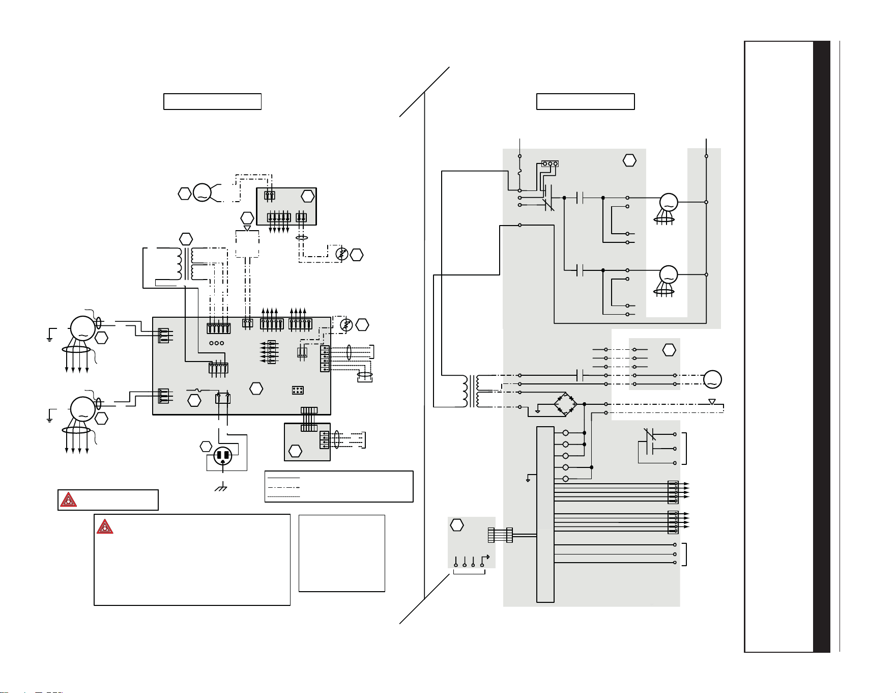
11. WIRING DIAGRAM
⚠WARNING
• Risk of electric shocks. Before performing any maintenance or servicing, always disconnect the unit from its
power source.
• This product is equipped with an overload protection (fuse). A blown fuse indicates an overload or a short-
circuit situation. If the fuse blows, unplug the product from the outlet. Discontinue using the unit and contact
technical support.
120 V, 60 Hz
W1
J5
J4
ELECTRONIC
ASSEMBLY
1
2
3
1
2
3
1234
12
12345
J8
J9
J11
J10
12
12345
J12
J13
J14
6
5
4
3
2
1
B
24 V
class 2
9.5 V
class 2
120V, 60Hz
Neutral
120 V, 60Hz
Line
CPU
K2
K4
K5
J5-2
J10-1J10-2
Line voltage factory wiring
Class 2 low voltage factory wiring
Class 2 low voltage field wiring
See note 1
120 V
neutral
1234512
12
J3
J2
J1
t˚
Damper motor
B
Override
switch
Furnace blower interlock
J14-1: NO
J14-2: COM
J14-3: nc
(optional; see notes 3 & 5)
DAMPER
ELECTRONIC ASSEMBLY
Defrost
temperature sensor
WIRING DIAGRAM
LOGIC DIAGRAM
Exhaust
fan motor
Supply
fan motor
J5-1
J5-3
J7-2
J7-1
J4-1
J4-3
J6-2
J6-1
K1
K3
K2
24 V
class 2
9.5 V
class 2
120 V
neutral
J9-1
J9-2
J9-3
J4-2
J9-4
J8-1
J8-2
J8-4
J8-5
K4
J12-2
J12-1
A1
Damper motor
J3-2
J3-1
J2-2
J2-1
F1
J12-5
J12-4
J12-3
J2-3
J2-4
J2-5
J11-2
J11-1
K1
K3
K5
J14-3
J14-1
J14-2
Furnace
blower
interlock
(optional; see
notes 3 & 5)
J14-4
J14-5
J14-6
Override
switch
(optional; see
notes 3 & 4)
Field wiring
remote control
(see notes 3 & 4)
BDM
B
Y
R
G
B
W
BR
BR
G
BR
BR
Y
Y
B
W
A2
A2
M3
T1
R1
A1
F1
(optional; see
notes 3 & 4)
VE0435A
Critical characteristic.
JU1
123
MED HI
321
HI MED
JU1
NOTES
1. Protected against fire with
UL listed/CSA Certified line fuse (3A, 3AG Type).
2. If any of the original wire, as supplied, must
be replaced, use the same equivalent wire.
3. Field wiring must comply with applicable
codes, ordinances and regulations.
4. Remote controls (class 2 circuit) available,
see instruction manual.
5. Furnace fan circuit must be class 2 circuit only.
COLOR CODE
BBLACK
BL BLUE
BR BROWN
GGREEN
RRED
W
WHITE
Y YELLOW
nc no connection
B
to A1-J12
Class 2
low voltage
factory wiring
to
A2-J2
12345
J15
Y
BL
R
W
nc
12345
J17
Y
BL
R
W
nc
From
supply motor
control cable
From
exhaust motor
control cable
Exhaust fan motor
M1
G
Y
BL
R
W
Control cable
Power cable
to A1-J17
Supply fan motor
M2
G
Y
BL
R
W
Control cable
Power cable
to A1-J15
to A1-J17
to A1-J15
12345
J15
nc
12345
J17
nc
From
supply motor
From
exhaust moto
r
W W
Door interlock switch
(magnetically actuated
S1
reed switch)
BL
BL
J2
J3
A3
Field wiring
remote control
(see notes 3 & 4)
4
3
2
1
Door interlock switch
J3-1
A3
J16
J3-2
J3-3
J3-4
J2
J16
J20
t˚
Thermistor
R2
1 2
ref: 24595_REV-A
Loading ...
Loading ...
Loading ...