INSTALLATION MANUAL
MANUEL D’INSTALLATION
MANUAL DE INSTALACIÓN
BUILT-IN DISHWASHER
LAVE-VAISSELLE ENCASTRÉ
LAVAVAJILLAS EMPOTRABLE
CATALOG NUMBER
NUMÉRO DE CATALOGUE
NÚMERO DE CATÁLOGO
BDW200M
BDW300M
BDW400M
BDW500M
Thank you for choosing BLACK+DECKER!
Merci d’avoir choisi BLACK+DECKER!
¡Gracias por elegir BLACK+DECKER!
PLEASE READ BEFORE RETURNING THIS PRODUCT FOR ANY REASON.
VEUILLEZ LIRE AVANT DE RETOURNER CE PRODUIT POUR QUELQUE
RAISON.
POR FAVOR, LEA ESTE MANUAL ANTES DE DEVOLVER EL PRODUCTO POR
CUALQUIER RAZÓN.
If you have a question or experience a problem with your BLACK+DECKER purchase, go to www.blackanddecker.com/
instantanswers If you can’t find the answer or do not have access to the Internet, call 844-299-0879 from 10:30 a.m. to 6:30
p.m. EST Mon. - Fri. to speak with an agent. Please have the catalog number available when you call.
Si vous avez une question ou rencontrez un problème avec votre achat Black+Decker, allez sur
www.blackanddecker.com/instantanswers Si vous ne trouvez pas la réponse ou n’avez pas accès à l’Internet, appelez au
844-299-0879 de 10h30 à 18h30 HNE du lun. au ven. pour parler avec un agent. Veuillez avoir le numéro de catalogue
disponible lorsque vous appelez.
Si tiene una pregunta o experimenta un problema con tu compra de BLACK+DECKER, vaya a
www.blackanddecker.com/instantanswers Si no puede encontrar las respuestas que necesita o no tiene acceso a Internet, llame
al 844-299-0879 desde las 10:30 a.m. a las 6:30 p.m. EST de lunes a viernes para hablar con un agente. Por favor, tenga el
número de catálogo a mano cuando llame.
SAVE THIS MANUAL FOR FUTURE REFERENCE.
CONSERVEZ CE MANUEL POUR TOUTE CONSULTATION ULTÉRIEURE.
GUARDE ESTE MANUAL PARA SU REFERENCIA FUTURA.
ACTIVATE
WARRANTY

Page 2
ENGLISH
INSTALLATION REQUIREMENTS
IMPORTANT SAFETY INSTRUCTIONS
CAUTION
• RISK OF ELECTRIC SHOCK DO NOT OPEN.
• This symbol indicates that dangerous voltage constituting a risk of electric
shock is present within your dishwasher.
• This symbol indicates that there are important operating and maintenance
instructions in the literature accompanying your dishwasher.
BEFORE YOU BEGIN
Read these instructions completely and carefully.
IMPORTANT!
• Observe all governing codes and ordinances.
• Note to Installer – Be sure to leave these instructions for the consumer’s and
local inspector’s use.
• Note to Consumer – Keep these instructions with your User Guide for future
reference.
• Skill Level – Installation of this dishwasher requires basic mechanical and
electrical skills. Proper installation is the responsibility of the installer. Product
failure due to improper installation is not covered under the appliance warranty.
• Completion Time – One to three hours. New installations require more time than
replacement installations.
IMPORTANT!
• The dishwasher MUST be installed to allow for future removal from the
enclosure if service is required.
• If you received a damaged dishwasher, you should immediately call W
Appliance Customer Service at 844-299-0879.
FOR YOUR SAFETY
Read and observe all CAUTIONS and WARNINGS shown throughout these
instructions. While performing installations described in this booklet, gloves and
safety glasses or goggles should be worn.
WARNING
This dishwasher comes with a heating element to heat the water. To avoid the
risk of a serious burn, don’t touch the heating element when the dishwasher is on.
WARNING
• To reduce the risk of electrical shock, fire, or injury to persons, the
installer must ensure that the dishwasher is completely enclosed at the
time of installation.
Page 3
ENGLISH
INSTALLATION REQUIREMENTS
READ CAREFULLY.
KEEP THESE INSTRUCTIONS.
If you have an installation problem, contact your dealer or installer. You are
responsible for providing adequate electrical, exhausting, and other connecting
facilities.
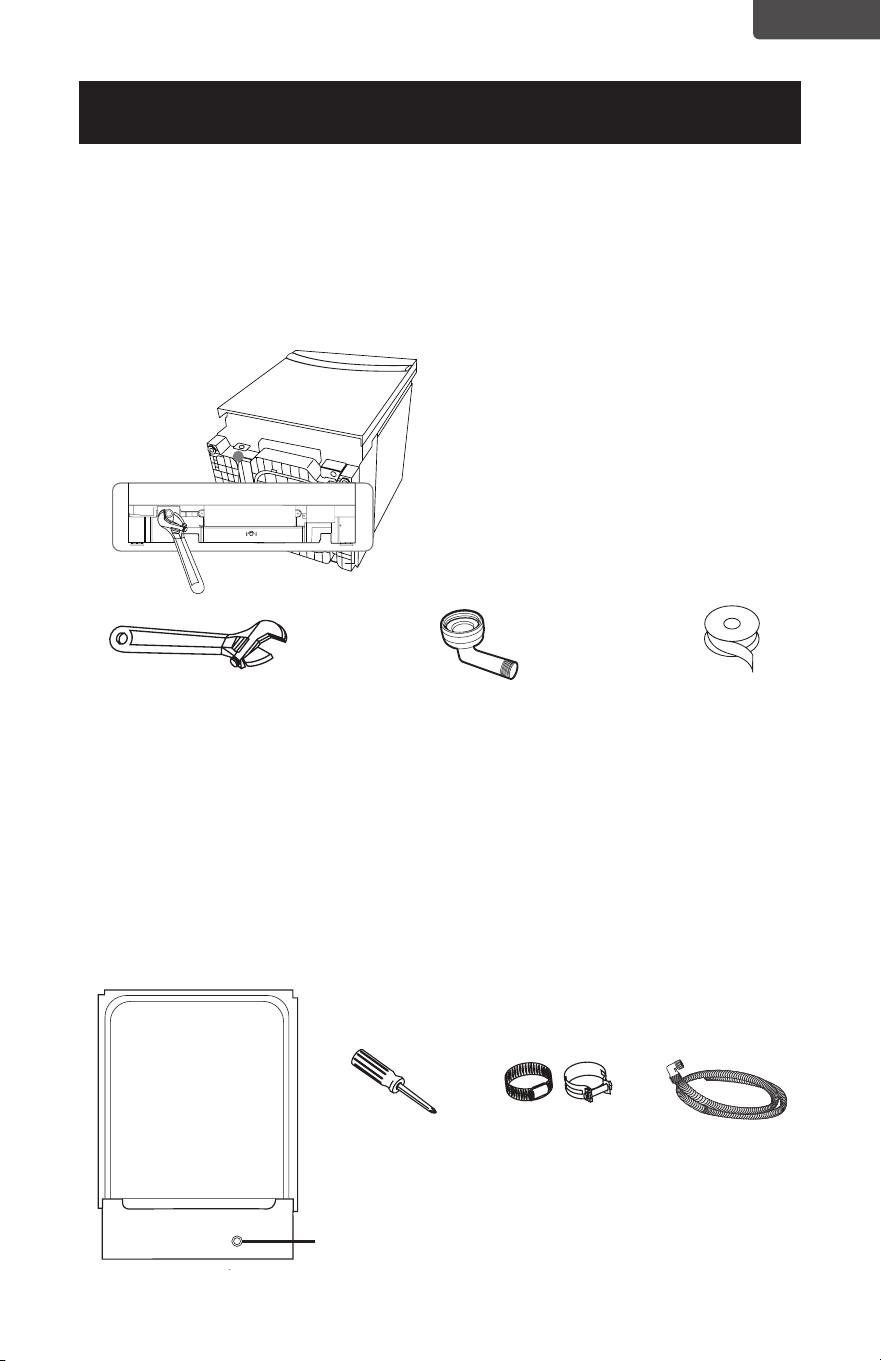
PREPARING TO INSTALL YOUR DISHWASHER
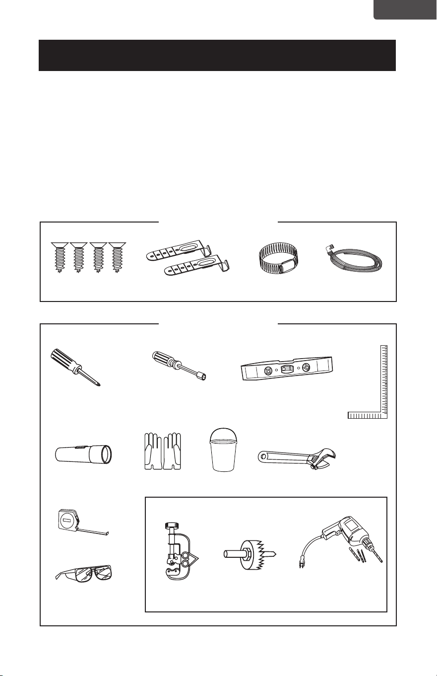
Parts supplied
Tools needed
New installations only
Wood screws (4)
Phillips screwdriver
Flashlight
Measuring tape
Safety glasses Tubing cutter Hole saw
set
Drill and bits
Gloves Bucket Adjustable wrench
Carpenters
square
1/4 in. and 5/16 in.
Nut driver
Level
Top mounting clips (2) Hose clamp Drain hose
Page 4
ENGLISH
Materials needed
Enclosure requirements
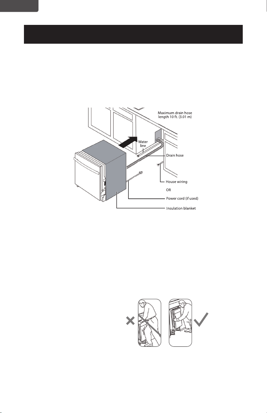
• The dishwasher must be installed so that the drain hose is no more than 10 feet
(3.01 m) in length, for proper drainage.
• This dishwasher is designed to be enclosed on the top and on both sides by a
standard residential kitchen cabinet unit.
• The installation enclosure must be clean and free of any obstructions.
• The enclosure must be at least 24 inches (61 cm) wide, 25 inches (63.5 cm)
deep, and 34 inches (86.4 cm) high.
• For the front door of the dishwasher to be flush with the front edge of the
counter top, the counter top must be 25 inches (63.5 cm) deep.
INSTALLATION REQUIREMENTS
90° fitting(3/4”). Other end
sized to fit water supply line)
Strain relief (for
electrical connections)
Hand
shut-o valve
Waste tee for
house plumbing
(if applicable)
Hot water line (min.
3/8 in. copper) kit
“T” connection Garden hose
connection
Screw-type hose
clamps
Coupler for
extending drain line
(if applicable)
Air gap
(if required)
Electrical cable
or power cord
(See Electrical
Requirements
section)
Teflon thread
seal tape
Three wire nuts (UL listed)
(two included in kit)
New installations only
Page 5
ENGLISH
INSTALLATION REQUIREMENTS
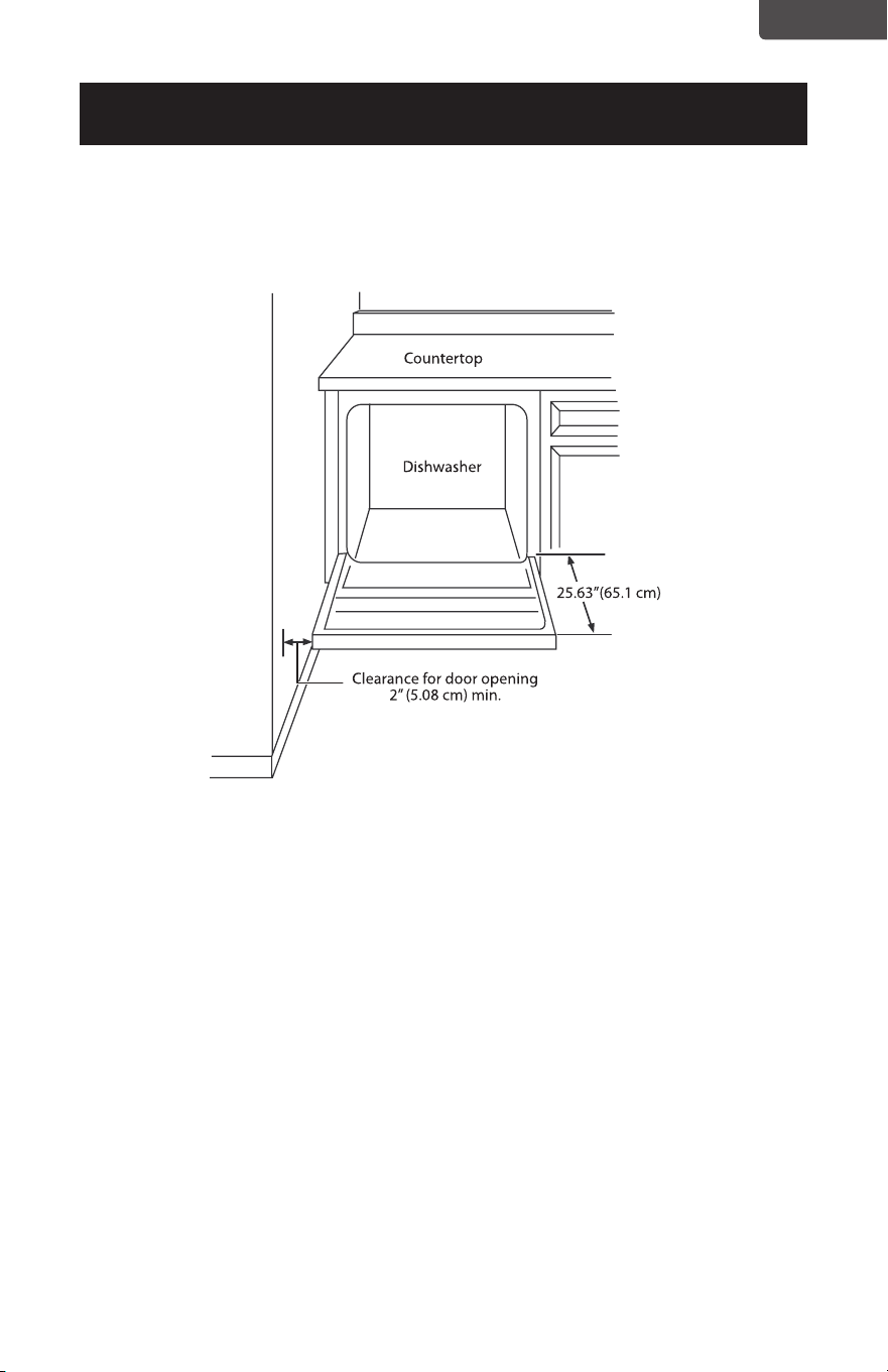
If installing into a corner, allow 2 in. (5.08 cm) min. clearance between dishwasher and
adjacent cabinet, wall, or other appliances. Allow 25.63 in. (65.1 cm) min. clearance
from the front of the dishwasher for opening the door.
Drain requirements
• Follow all local codes and ordinances.
• Do not exceed 10 ft. (3.01 m) of drain hose.
• Do not connect the drain lines from other devices to the dishwasher drain hose.
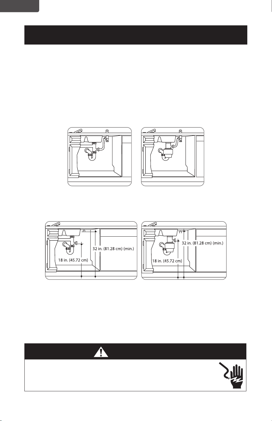
• The dishwasher must be connected to a waste line with an air gap (not
provided) or a 32 in. (81.28 cm) high (min.) drain loop, depending on local
codes and ordinances, to prevent back ow into the dishwasher.
• An air gap must be used if the waste tee or garbage disposal connection is less
than 18 in. (45.72 cm) above the oor, to prevent siphoning.
Drain preparation
The type of drain installation required depends on the answers to the following
questions:
• Do local codes or ordinances require an air gap?
• Will the waste tee or garbage disposal connection be less than 18 in. (45.72 cm)
above the oor?
• Will installation have a drain loop less than 32 in. (81.28 cm) above the oor?
If the answer to ANY of these questions is YES, Method 1 MUST be used.
Otherwise, either Method 1 or Method 2 may be used.
Page 6
ENGLISH
INSTALLATION REQUIREMENTS
Caution:
• An air gap MUST BE USED if the drain hose is connected to a waste tee or garbage
disposal lower than 18 in. (45.72 cm) above the floor.
• Failure to provide the proper drain connection height with an air gap or 32 in. (81.28
cm) (min.) high drain loop will result in improper draining of the dishwasher.
Install the waste tee or garbage disposal connection and air gap according to
manufacturer’s instructions.
Method 1 - Air gap with a waste tee or garbage disposal connection
Method 2 - High drain with a waste tee or garbage disposal connection
You must provide a method to attach the drain hose to the underside of the
countertop.
Electrical requirements
• This appliance must be supplied with 120V, 60 Hz, and it must be connected
to its own, properly grounded branch circuit that is protected by a 15 or 20
ampere circuit breaker or time delay fuse.
• Wiring must be two wire with ground.
• If the electrical supply does not meet the above requirements, call a licensed
electrician before proceeding.
WARNING
• Remove the house fuse or open the circuit breaker before beginning
the installation. Do not use an extension cord or adapter plug with this
appliance.
Page 7
ENGLISH
INSTALLATION REQUIREMENTS
Grounding instructions
Grounding Instructions – Cable Direct
This appliance must be connected to a grounded metal, permanent wiring
system, or an equipment grounding conductor must be run with the circuit
conductors and be connected to the equipment grounding terminal or lead on
the appliance.
Grounding Instructions – Power Cord Models
This appliance must be grounded. In the event of a malfunction or breakdown,
grounding will reduce the risk of electrical shock by providing a path of least
resistance for electric current. The plug must be plugged into an appropriate
outlet that is installed and grounded in accordance with local codes and
ordinances.
Direct Wire Method
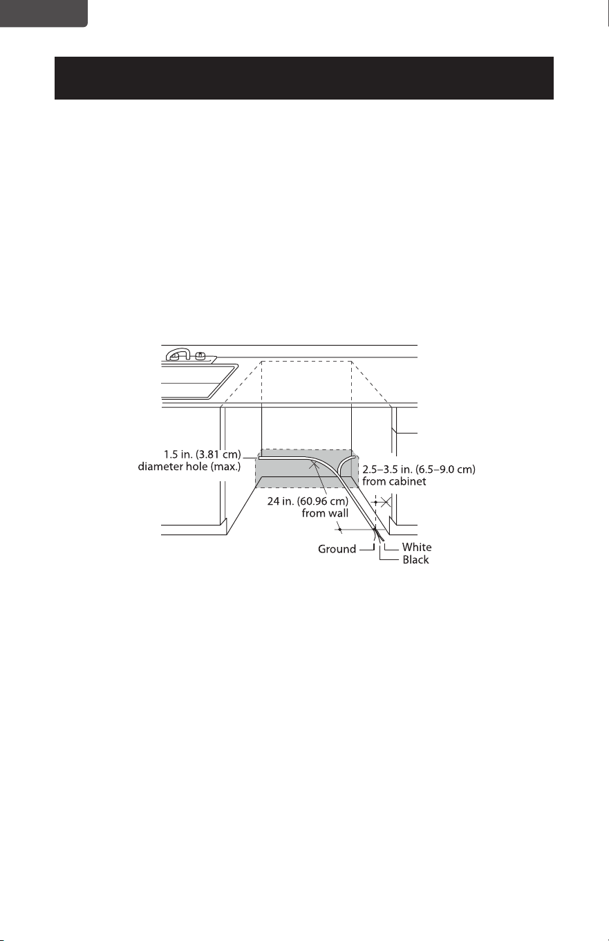
• The cable must be routed as shown in Cabinet preparation and wire routing,
and extend a minimum of 24 in. (60.96 cm) from the rear wall.
• Use exible, armored, or nonmetallic sheathed, copper wire with grounding
wire that meets the wiring requirements for your home and local codes and
ordinances.
• Use a UL Listed/CSA Approved strain relief.
Power Cord Method
• Install a 3-prong grounding type receptacle. The wall outlet can be installed
in a cabinet or on a wall adjacent to the undercounter space in which the
dishwasher is to be installed.
• Use power cord kit (part number 5304504505) under Smart Choice brand
marked with Dishwasher Install Kit With Power Cord. The power cord and
connections must comply with local codes and ordinances.
• The recommended power cord length is 54 in. (1.4 m) min. and 64 in. (1.6 m)
max.
WARNING
• The improper connection of the equipment grounding conductor can
result in a risk of electric shock. Check with a qualified electrician or
service representative if you are in doubt that the appliance is properly
grounded.
Page 8
ENGLISH
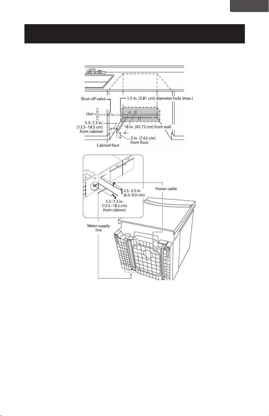
Preparing the hot water line
• The water connection is on the left side of dishwasher.
• The hot water line may enter the opening from either side, the rear, or the floor
within the shaded area.
• The hot water line may pass through the same hole as the electrical and drain hose.
Or, you can drill an additional 1.5 in. (3.81 cm) maximum diameter hole for the hot
water line.
• If a power cord with a plug is used, the hot water line may not pass through the
same hole as the power cord.
INSTALLATION REQUIREMENTS
Cabinet preparation and wire routing
• The wiring may enter the opening from either side, the rear, or the floor within
the shaded area.
• The electrical connection is on the front right of the dishwasher.
• Drill a 1.5 in. (3.81 cm) maximum diameter hole to run the electrical cable
through the wall of the cabinet.
• The hole must be free of sharp edges. If the cabinet wall is metal, the hole edge
must be covered with a bushing or rubber grommet.
• Cable direct connections may pass through the same hole as the drain hose and
hot water line, but power cords with plugs must pass through a separate hole.
Page 9
ENGLISH
INSTALLATION REQUIREMENTS
Connecting the water line to the water supply
1. Turn o the water supply.
2. Install a hand shut-o valve in an accessible location, such as under the sink. This is
optional, but strongly recommended, and may be required by local codes.
3. Install the hot water inlet line, using at least 3/8 in. O.D. copper tubing. Route the
line as shown in the figure above and extend it forward at least 18 in. (45.72 cm)
from the rear wall of the enclosure.
4. Adjust the water heater to a temperature of 120° F to 150° F (49° C to 65° C).
5. Flush the water line to clean out any debris.
Note: The hot water pressure must be between 20 and 120 psi
(138 and 827 kPa).
Page 10
ENGLISH
INSTALLATION INSTRUCTIONS
Step 1: Check the door balance
Caution:
• Opening the door of your dishwasher before it is installed will cause it to tip forward.
Do not open the door until you are ready to install your dishwasher.
• If it is necessary to open the door,
hold the top of the dishwasher
securely with one hand and hold
the door with the other hand.
1. Hold the top of the dishwasher
firmly.
2. Open the door slowly, then
release it. If the door drops,
increase the spring tension. If
the door closes, decrease the
spring tension.
3. Continue moving the spring
pin until the door is balanced.
Adjust both springs to the same
tension.
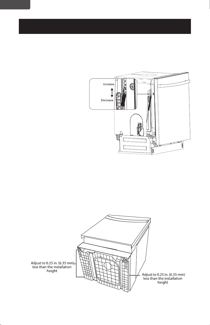
Step 2: Adjust the leveling legs
1. Move the dishwasher close to the installation location and lay it on its back.
NOTE: Make sure that the leveling feet are loosened before standing the dishwasher
upright. They may be tight from shipping/packaging.
2. Measure the installation height and the dishwasher height.
3. Extend the leveling legs out from the dishwasher base 0.25 in. (6.35 mm) less than
the installation height.
Page 11
ENGLISH
INSTALLATION INSTRUCTIONS
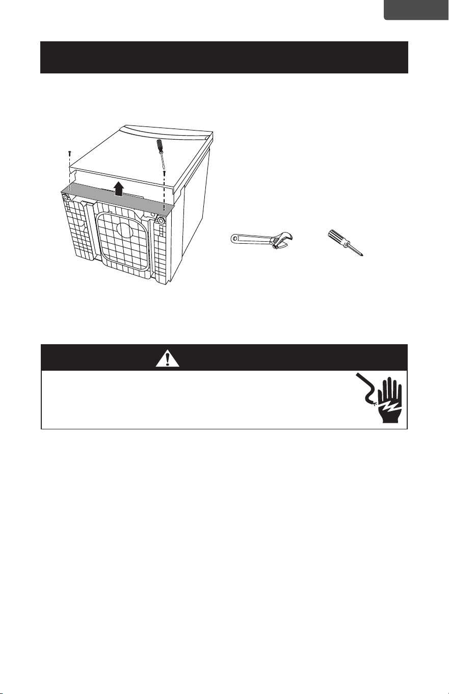
Step 3: Remove the toekick
1. Remove the two toekick screws with a Phillips screwdriver, then remove the toekick.
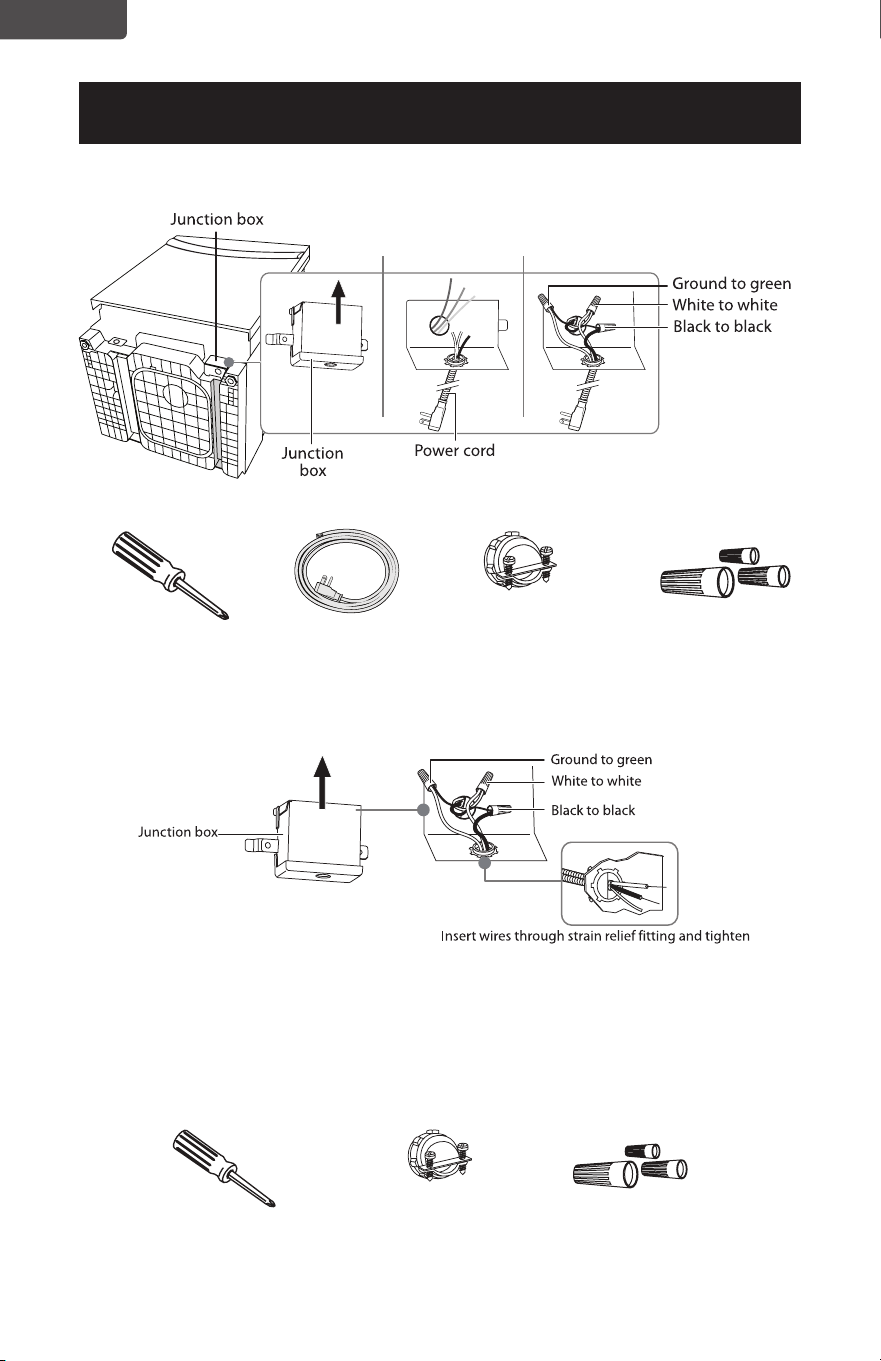
Step 4: Install to power
• Turn o the electricity to the dishwasher’s electrical circuit.
• Make sure that the electrical power is turned o at the source.
Power cord
1. Remove the junction box cover on the front right of the dishwasher.
2. Make sure that the junction box’s electrical wires are pulled inside of the junction
box.
3. Remove the lock nut from the strain relief, then push the strain relief into the round
opening of the junction box.
4. Install the lock nut on the strain relief from inside the junction box.
5. Insert the ends of the power cord’s electrical wires into the junction box through
the strain relief.
6. Connect the incoming white (or ribbed) wire to the dishwasher’s white wire, the
black (or smooth) wire to the dishwasher’s black wire, and the ground wire to the
dishwasher’s green wire. Use cUL/UL listed wire nuts of the appropriate size.
7. Tighten the strain relief screws and lock nut to stabilize the power cord’s
electrical wires, then make sure that all of the connections are secure.
8. Replace the junction box cover on the right front of the dishwasher. Be sure that
the wires are not pinched under the cover.
Note: If you have trouble replacing the junction box cover, loosen the screws on the
strain relief.
Adjustable wrench Phillips screwdriver
WARNING
• If your house wiring is not 2-wire with a ground, a ground must be
provided by the installer.
• If your house wiring is aluminum, be sure to use cUL/UL Listed anti-
oxidant compound and aluminum-to-copper connectors.
Page 12
ENGLISH
INSTALLATION INSTRUCTIONS
Phillips screwdriver
Phillips screwdriver Strain relief (for
electrical connections)
Three wire nuts
(UL listed)
Power cord Strain relief (for
electrical connections)
Three wire nuts
(UL listed)
Direct wiring
1. Remove the junction box cover from the power supply junction box on the wall.
2. Locate the three dishwasher wires, (white, black, and green) with stripped ends,
then insert the dishwasher wires through the small hole in the junction box.
3. Secure the house wiring to the bottom of the junction box with a strain relief fitting.
4. Use wire nuts to connect incoming ground to green, white to white, and black to
black.
5. Replace the junction box cover. Make sure that no wires are pinched under the
cover.
Page 13
ENGLISH
INSTALLATION INSTRUCTIONS
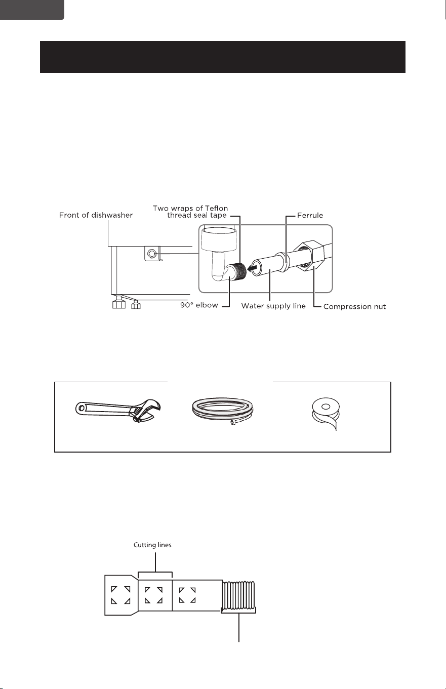
Step 5: Install the 90° water supply elbow
1. Wrap the male thread of the 90° elbow with Teflon thread seal tape twice. Do not
use plumber’s putty.
2. Install the 90° elbow onto the water valve. Do not overtighten the 90° elbow. The
water valve bracket could bend or the water valve fitting could break.
3. Position the end of the elbow to face the floor when the dishwasher is upright.
Step 6: Install the drain hose
1. Make sure that the leveling feet are loosened before standing the dishwasher
upright. They may be tight from shipping/packaging.
2. Turn the dishwasher upright.
3. Slide a screw-type hose clamp onto the right-angled end of the drain hose.
4. Install the drain hose to the dishwasher drain outlet on the back of the dishwasher,
then tighten the screw-type hose clamp.
Adjustable wrench
Phillips screwdriver Screw-type hose
clamps
Drain hose
Drain hose installation
hole
Back of dishwasher
90
o
fitting (3/4”). The other end should
be sized to fit the water supply line.
Teflon thread
seal tape
Page 14
ENGLISH
INSTALLATION INSTRUCTIONS
Step 7: Inserting the drain hose through the cabinet
• Insert the drain hose into the hole in the cabinet wall. If a power cord is used, guide
the end through a separate hole.
Tip: Position the water line and house wiring on the floor to avoid interfering with the
base of the dishwasher.
Step 8: Slide the dishwasher partially into the cabinet
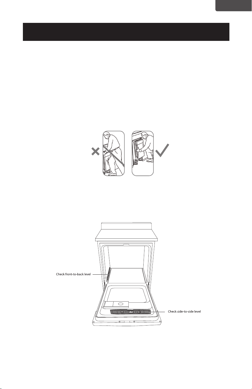
CAUTION
Do not push against the front panel with your knees. Damage will occur.
1 Position the dishwasher in front of the opening, then slide the dishwasher into
the opening a few inches at a time.
2 Pull the drain hose through the opening under the sink as you proceed. Stop
when the dishwasher is a few inches in front of the adjacent cabinetry.
3 Make sure that the drain hose is not kinked under the dishwasher and that
there is no interference with the water line, wiring, or any other component.
Do not push against the
front door panel with
your knees. You will
damage the front panel.
Page 15
ENGLISH
INSTALLATION INSTRUCTIONS
Step 9: Position the dishwasher under the countertop
1. Make sure that the wires are secure under the dishwasher and not pinched or in
contact with door springs or other
Tip: Check tub insulation blanket, if equipped. It should be positioned so it is not
bunched up or interfering with door springs. Check by opening and closing the
door.
2 Push the dishwasher into the cabinet. The front corners of the dishwasher door
should be flush with the cabinet doors. Be careful not to dent the front panel with
your knees or damage the countertop or cabinets with dishwasher parts.
Note: You will not have access to the back leveling legs once the dishwasher is put in
place.
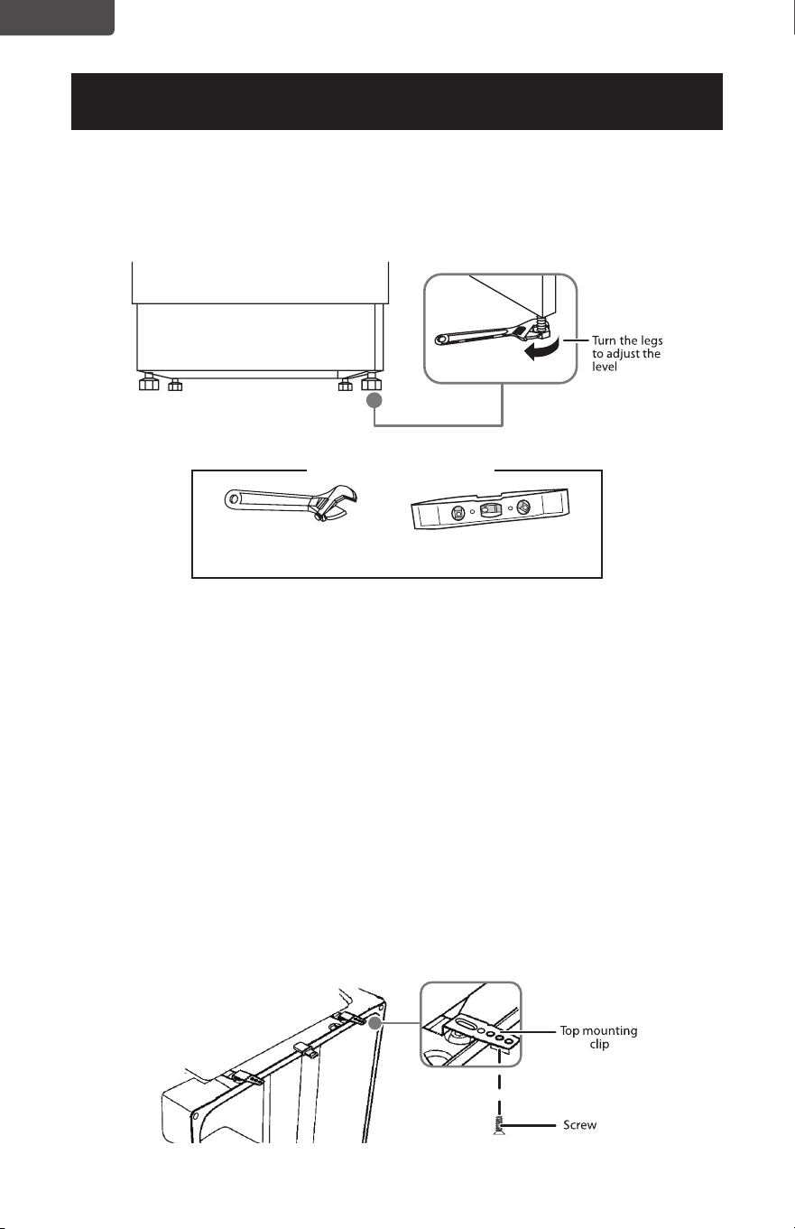
Step 10: Level the dishwasher
IMPORTANT!
The dishwasher must be level for proper dish rack operation and wash performance.
1 Open the door, then place a level on the door and on the rack track inside the
tub to make sure that the dishwasher is level.
2 Level the dishwasher by adjusting the four leveling legs individually.
Tip: Pull the lower rack out about halfway. Make sure that the rack does not roll
forward or back into the dishwasher. If the rack rolls in either direction, you
must level the dishwasher again.
Note: You may need to pull your dishwasher out of the cabinet if major
adjustments to the four leveling legs are required.
Do not push against the
front door panel with
your knees. You will
damage the front panel.
Reposition the
dishwasher by
grasping both sides
with your hands.
Page 16
ENGLISH
INSTALLATION INSTRUCTIONS
3 If the door hits the tub, the dishwasher is not installed correctly. Adjust the leveling
legs to align the door to the tub.
Note: Keep the dishwasher level.
Step 11: Securing the dishwasher to the countertop
• For countertops made of wood or materials that won’t be damaged by drilling, use
Method 1.
• For countertops made of granite, marble, or other materials that could be damaged
by drilling, use Method 2.
• If the gap between the control panel and the cabinet is less than 0.4 in. (10 mm),
use Method 2.
Method 1
1 Insert the long top mounting clips into the slot.
2 Bend the brackets to secure them to the dishwasher tub.
3 Secure the dishwasher to the countertop through the holes in the brackets,
using the screws provided.
IMPORTANT!
Drive the screws straight and flush. Protruding screw heads will scratch the top of the
control panel and interfere with the door closing.
Adjustable wrench
You’ll need
Level
Page 17
ENGLISH
INSTALLATION INSTRUCTIONS
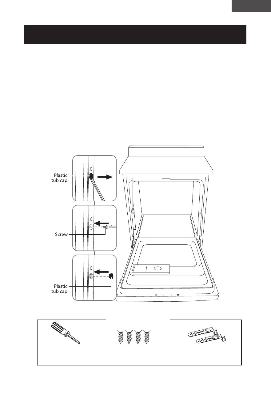
Method 2
1 Remove the plastic tub caps from the inside of the dishwasher tub.
2 Drive a wood screw through the hole in the side of the dishwasher into the
cabinet frame.
IMPORTANT!
Drive the screws straight and flush. Protruding screw heads will scratch the side if the
dishwasher. This method is for attaching the dishwasher to the side of the cabinet,
and it should be done when the countertop is made of granite or other breakable
materials.
3 Reinsert the plastic tub caps.
You’ll need
Phillips screwdriver Wood screws (2)
(two for each method)
Top mounting clips (2)
Page 18
ENGLISH
INSTALLATION INSTRUCTIONS
Step 12: Connecting the water supply line
1. Connect water supply line to 90˚ elbow.
2. Slide compression nut, then ferrule, over the end of the water line.
3. Insert water line into 90˚ elbow.
4. Slide ferrule against elbow and secure with compression nut.
IMPORTANT!
Make sure that the door spring does not rub or contact the water supply line or drain
hose. Test by opening and closing the door. Reroute the lines if interference occurs.
Step 13: Connecting the drain hose
IMPORTANT!
Follow all local codes and ordinances.
1 Cut on the marked line as required for your installation. The drain hose’s molded
end will t 5/8” or 1” diameter connections on the air gap, waste tee, or garbage
disposal.
Back of dishwasher
IMPORTANT!
Do not cut corrugated portion of hose.
You’ll need
Adjustable wrench Hot water line kit Teflon thread seal tape
Page 19
ENGLISH
INSTALLATION INSTRUCTIONS
2. If a longer drain hose is required, you can add up to 42” (1.1 m) of length,
for a total of 10 ft. (3.01 m) to the factory installed hose. Use 5/8” or 7/8”
inside diameter hose and a coupler to connect the two hose ends. Secure the
connection with screw-type hose clamps.
IMPORTANT!
For proper drain operation, the total drain hose length must not exceed 10 ft. (3.01 m).
3. Secure the drain hose to the air gap, waste tee, or garbage disposal with
a screw-type clamp, using the appropriate method below. See “Drain
preparation on page 7, if you do not know which method to to use.
Method 1 - Air gap to a waste tee or garbage disposal.
Method 2 - High drain loop to a waste tee or garbage disposal.
Page 20
ENGLISH
INSTALLATION INSTRUCTIONS
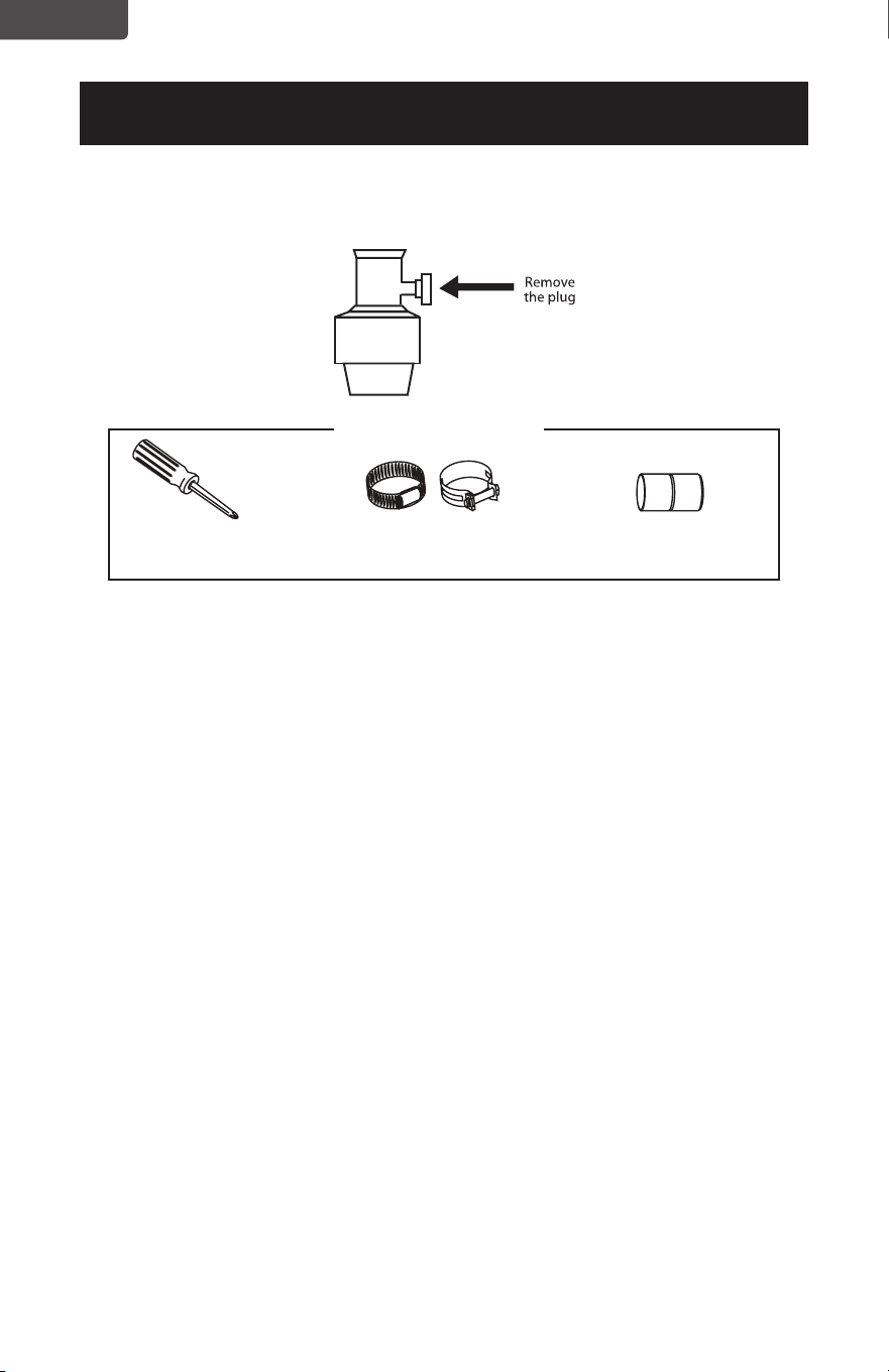
4. If connecting the drain line to a garbage disposal, make sure that the drain
plug has been removed. Your dishwasher will not drain if the plug is left in
place.
Step 14: Performing a pre-test check
Review this list after installing your dishwasher to avoid problems or charges for
a service call not covered by your warranty.
• Make sure that power is turned OFF.
• Open the door and remove all foam and paper packaging.
• Locate the User Guide in the literature package.
• Read the User Guide for operating instructions.
• Check the door opening and closing. If the door does not open and close freely,
or tends to fall, check the spring adjustments. See Step 1: Check the door
balance.
• Make sure that the wiring is secure under the dishwasher and not pinched or
in contact with door springs or other components. See Step 9: Position the
dishwasher under the countertop.
• Check the door alignment with the tub. If the door hits the tub, level the
dishwasher. See Step 10: Level the dishwasher.
• Pull the lower rack out about half way. Make sure that it does not roll back or
forward on the door. If the rack moves, adjust the leveling legs. See Step 10:
Level the dishwasher.
• Check the door alignment with the cabinet. If the door hits the cabinet,
reposition or relevel the dishwasher. See Step 10: Level the dishwasher.
• Make sure that water supply and drain lines are not kinked or in contact with
other components. Any contact with the motor or dishwasher frame could
cause a noise. See Step 8: Slide the dishwasher partially into the cabinet.
Phillips screwdriver Screw-type hose clamps Coupler for extending
drain line (if applicable)
You’ll need

Page 21
ENGLISH
INSTALLATION INSTRUCTIONS
• Turn on the sink hot water faucet and verify the water temperature. Incoming
water temperature must be between 120°F and 150°F. A minimum of 120°F
temperature is required for best wash performance. See Preparing the hot
water line.
• Add a half gallon (2 l) of water to the bottom of the dishwasher to lubricate the
pump seal.
• Turn on the water supply. Check for leaks. Tighten connections if needed.
• Remove any protective lm (if present) from the control panel and door.
Step 15: Wet testing the dishwasher
1. Turn on the power supply (or plug the power cord into the outlet, if equipped).
2. Turn on your dishwasher (refer to the User Guide for instructions).
3. Close the door, select the Rinse only cycle, and press START/Cancel.
4. Make sure that water enters the dishwasher. If water does not enter the
dishwasher, check to be sure that water and power are turned on.
5. Check for leaks under the dishwasher. If a leak is found, turn the power supply
off, then tighten connections. Restore power after the leak is corrected.
6. Check for leaks around the door. A leak around the door could be caused by
door rubbing or hitting against adjacent cabinetry. Reposition the dishwasher
if necessary. See “Step 9: Position the dishwasher under the countertop.
7. When the dishwasher is draining, check the drain lines. If leaks are found, turn
power off at the breaker and correct plumbing as necessary.
8. Restore the power after corrections are made. See “Step 12: Connecting the
water supply line.
9. Open the dishwasher door and make sure that most of the water has drained.
If not, check that the disposer plug has been removed and/or the air gap is not
plugged. See “Step 13: Connecting the drain hose. Also check the drain line for
kinking.
10. Run the dishwasher through another ll and drain cycle. Check for leaks and
correct if required.
Step 16: Replacing the toekick
• Place the toekick against the legs of the dishwasher. The slots should align with
the toekick bracket screw holes. Allow the toekick to touch the oor. Install the
toekick screws.
Note: Make sure that you install the toekick in the correct direction. The toekick
should be aligned correctly with the junction box.
Phillips screwdriver
You’ll need

BLACK & DECKER, BLACK+DECKER, the BLACK & DECKER and BLACK+DECKER
logos and product names and the orange and black color scheme are trademarks of
The Black & Decker Corporation, used under license. All rights reserved.
Product in this box may differ slightly from that pictured. Does not affect function. Not
all accessories shown in photography are included in this package.
Imported by W Appliance, Inc., 1356 Broadway, New York, NY 10018
Customer Service: 844-299-0879
October 2024 Printed in China
ACTIVATE
WARRANTY