Loading ...
Loading ...
Loading ...
ModeBsEquipped with LeveB[ng[eBegs
Toreducetheriskoftippingof therange,
tile rangemustbesecuredto thefloorbyproperly
installedanti-tipbracketsandscrewspackedwith the
range.Thesepartsarelocatedin a plastic:bagin the
oven.Failureto installtheantPtipbracketswill allowthe
rangeto tip overif excessiveweightisplacedonan
opendoororif achildclimbsuponit. Seriousinjury
mightresultfromspilledhot liquidsorfromtherange
itself.
Followtheinstructionsbelowto installtheantPtip
brackets.
If rangeisevermovedto adifferentlocation,theantPtip
bracketsmustalsobemovedandinstalledwith the
range.Tocheckfor properinstallation,seestep5.
ToolsRequired:
5/16"(0,79cm)Nutdriveror FlatHeadScrewdriver
AdjustableWrench
ElectricDrill
3/16"(0,5cm)DiameterDrillBit
3/16"(0,5cm)DiameterMasonryDrillBit(if installingin
concrete)
Bracketsattachto the floorat tile backof tile rangeto
holdbothrearleglevelers.Whenfasteningto thefloor,
besurethatscrewsdo notpenetrateelectricalwiringor
plumbing.Thescrewsprovidedwillworkineitherwood
orconcrete.
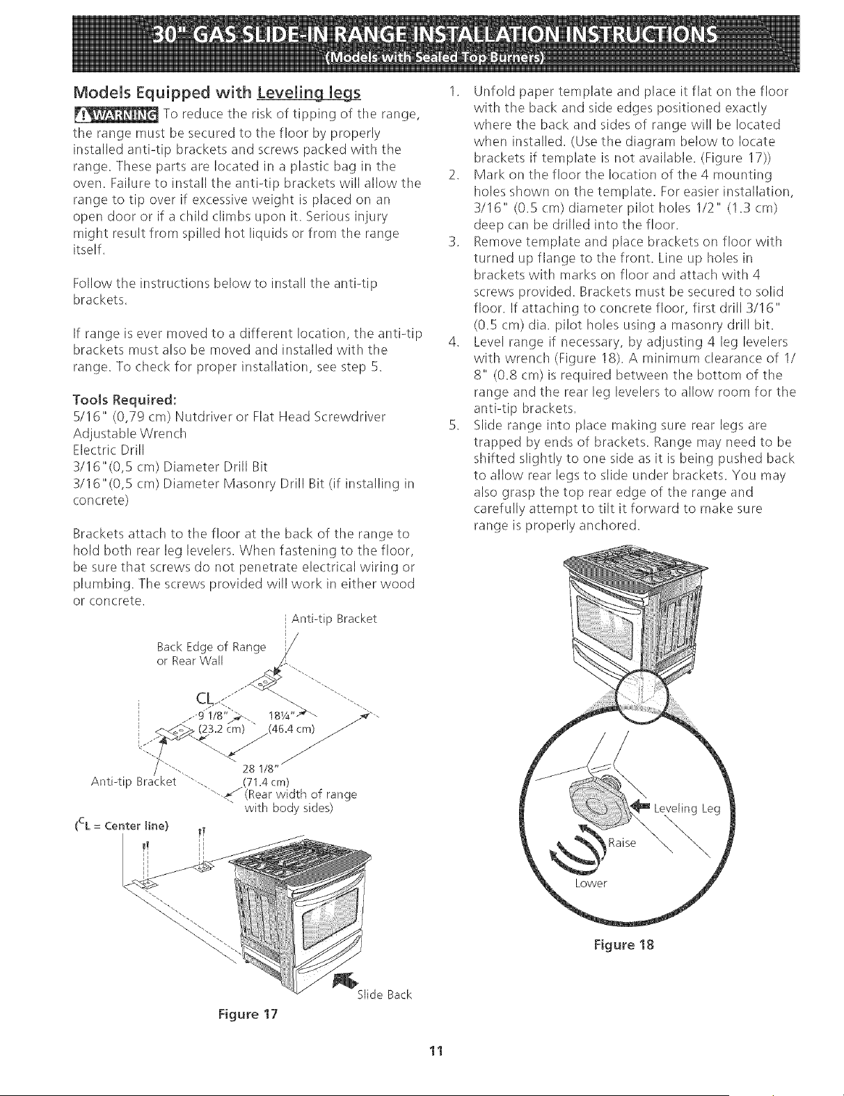
AntPtip Bracket
Back Edge of Range ¢
or Rear Wall "<_ _._.....
...-9us"_... 18w'>\ ._'-.
'<:"/\'-.. 28 !/8"
AntPtip Bracket ""--. (71.4cm)
"-.#/(Rear width of range
with body sides)
(eL = Center line)
1. Unfold paper template and place it flat on the floor
with the back and side edges positioned exactly
where the back and sides of range will be located
when installed. (Use the diagram below to locate
brackets if template is not available. (Figure 17))
2. Mark on the floor the location of the 4 mounting
holes shown on the template. For easier installation,
3116" (0.5 cm) diameter pilot holes 1/2" (1.3 cm)
deep can be drilled into the floor.
3. Remove template and place brackets on floor with
turned up flange to tile front. Line up holes in
brackets with marks on floor and attach with 4
screws provided. Brackets must be secured to solid
floor. If attaching to concrete floor, first drill 3/16"
(0.5 cm) dia. pilot holes using a masonry drill bit.
4. Level range if necessary, by adjusting 4 leg levelers
with wrench (Figure 18). A minimum clearance of I/
8" (0.8 cm) is required between the bottom of the
range and the rear leg levelers to allow room for the
antPtip brackets.
5. Slide range into place making sure rear legs are
trapped by' ends of brackets. Range may' need to be
shifted slightly to one side as it is being pushed back
to allow rear legs to slide under brackets. You may
also grasp the top rear edge of the range and
carefully attempt to tilt it forward to make sure
range is properly anchored.
Figure 18
Figure 17
Slide Back
11
Loading ...
Loading ...
Loading ...