iNSTALLATiON AND SERVICEMUST BE PERFORMED BY A QUAUFJED iNSTALLER.
iMPORTANT: SAVE FOR LOCAL ELECTRICAL iNSPECTOR'S USE.
READ AND SAVE THESE INSTRUCTIONS FOR FUTURE REFERENCE,
if the information in this manual is not followed exactly, a fire or
explosion may result causing property damage, personal injury or death.
FOR YOUR SAFETY:
-- Do not store or use gasoline or other flammable vapors and liquids in the
vk[n[ty of this or any other appliance.
-- WHATTO DO JFYOU SMELLGAS:
• Do not try to light any appliance,
• Do not touch any e[ectrkaJ switch; do not use any phone in your building.
• immediately ca[[ your gas supplier from a neighbor's phone. Follow the
gas supp[[er's instructions,
• if you cannot reach your gas supplier, ca[[ the fire department.
-- Installation and servke must be performed by a qualified installer,
service agency or the gas supplier.
Appliances installed in the
state of Massachusetts:
This Appliance can only be
installed in the state of
Massachusetts by a
Massachusetts licensed plumber
or gasfitter,
This appliance must be installed
with a three (3) foot / 36 in, long
flexible gas connector,
A"T" handle type manual gas
valve must be installed in the gas
supply line to this appliance
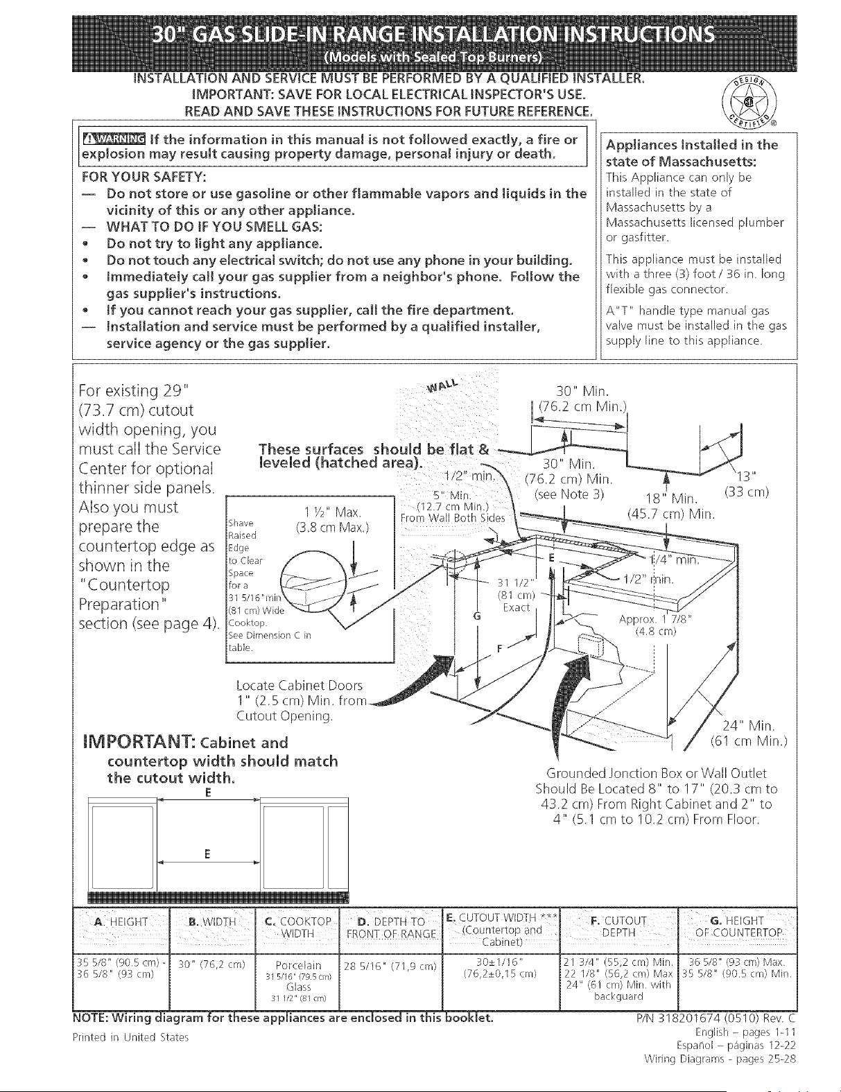
For existing 29"
(73.7 cm) cutout
width opening, you
must call the Service
Center for optional
thinner side panels.
Also you must
prepare the
countertop edge as
shown in the
"Countertop
Preparation"
section (see page 4).
30" Min.
IMPORTANT: Cabinet and
countertop width should match
the cutout width.
E
E
Grounded Jonction Box or Wall Outlet
Should BeLocated 8" to 17" (20.3 cm to
43.2 cm) From Right Cabinet and 2" to
4" (5.1 cm to 10.2 cm) From Floor.
0,W,D i
35 5/8" (905cm)- 30" (76,2 cm)
36 518" (93 cm
NOTE:Wiring di gram for thes
E CUTOUT WID] H ***
ccOoKTOP D:DiP-rHTO _ :
WDTH [ FRONT OF RANGE (Countertop and
I , Cabinet)
Porcelain 28 5/I6" (71,9 cm} 30±1/16"
31 5116" (79.5 cm) (76,2±0,I 5 cm)
Glass
31 1/2" (81 an)
21 3/4" (55,2 cm) Min.
22 I18" (56,2 cm) Max
24" (61 crn) Min with
backguard
Printed in United States
appliances are enclosed in this booklet.
36 518" @3 cm) Max
35 5/8" (905 cm) Min
WN 318201674 (0510) Rev. C
English - pages I-11
Espanol - paginas 12-22
Wiring Diagrams - pages 25-28
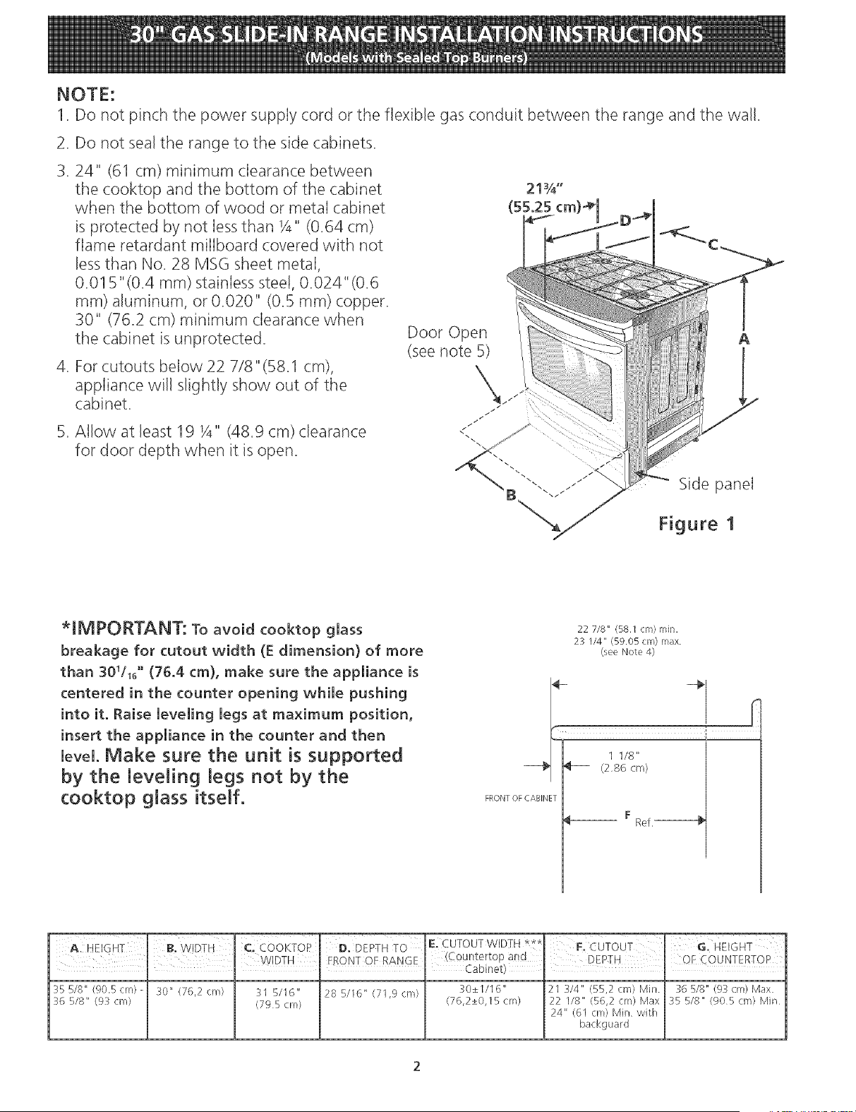
NOTE:
1. Do not pinch the power supply cord or the flexible gas conduit between the range and the wall.
2. Do not seal the range to the side cabinets.
3.24" (61 cm) minimum clearance between
the cooktop and the bottom of the cabinet
when the bottom of wood or metal cabinet
is protected by not less than Y4" (0.64 cm)
flame retardant milIboard covered with not
less than No. 28 MSG sheet metal,
0.01B"(0.4 ram) stainless steel, 0.024"(0.6
mm) aluminum, or 0.020" (0.5 ram) copper.
30" (762 cm) minimum clearance when
the cabinet is unprotected.
4. For cutouts below 22 7/8" (B8.1 cm),
appliance will slightly show out of the
cabinet.
B. Allow at least 19 Y4" (48.9 cm) clearance
for door depth when it is open.
Door Open
(see note 5)
<
21¾"
(55.25 cm
A
Side panel
Figure 1
*IMPORTANT: To avoid cooktop glass
breakage for cutout width ([ dimension) of more
than 301/16°°(76.4 cm), make sure the appliance is
centered in the counter opening while pushing
into it. Raise leveling legs at maximum position,
insert the appliance in the counter and then
level. Make sure the unit is supported
by the leveling legs not by the
cooktop glass itself.
22 7/8" (58.1cm) rain.
23 I/4" (59.05cm) max
(see Note 4)
- -€_
i
1 I/8"
_ (2,86 cm)
FRONT OF CABINET
__ F Ref,--------@
355/8" (90,5cm)- 30" (76,2 cm) 31 5/16" 28 5/16" (71,9cm) 30±1/16" 21 3/4" (55,2 cnl) Min 36 5/8" (93 c:m) Max
3(; 5/8" (9:3 cm) (795cm) (76,2±0,15cm) 22 1/8" (56,2 era) Max 35 5/8" (905cm) Min
24" (61 cm) Min with
backguard
2
Important Notes to the Installer
1. Readallinstructionscontainedintheseinstallation
instructionsbeforeinstallingrange.
2. Removeallpackingmaterialfromtheoven
compartmentsbeforeconnectingthegasandelectrical
supplytotherange.
3. Observeallgoverningcodesandordinances.
4. Besureto leavetheseinstructionswithtileconsumer.
Important Note to the Consumer
KeeptheseinstructionswithyourUse&Care Guide for
future reference.
IMPORTANT SAFETY
INSTRU S
Installation of this range must conform with local codes
or, in the absence of local codes, with the National Fuel
Gas Code ANS! Z223. I/NFPA .54qatest edition.
This range has been design certified by CSA
International. As with any appliance using gas and
generating heat, there are certain safety precautions you
should follow. You will find them in the Use and Care
Guide, read it carefully.
• Be sure your range is installed and grounded
property by a quaIified installer or service
technician.
This range must be electrically grounded in
accordance with local codes or, in their absence,
with the National Electrica! Code ANSI/NFPA No.
70--latest edition. See Grounding Instructions.
• Before installing the range in an area covered with
linoleum or any other synthetic floor covering,
make sure the floor covering can withstand heat at
least 90°F above room temperature without
shrinking, warping or discoloring. Do not install the
range over carpeting unless you place an insulating pad
or sheet of _/4"(I 0,16 cm) thick plywood between the
range and carpeting.
• Make sure the wall coverings around the range
can withstand the heat generated by the range.
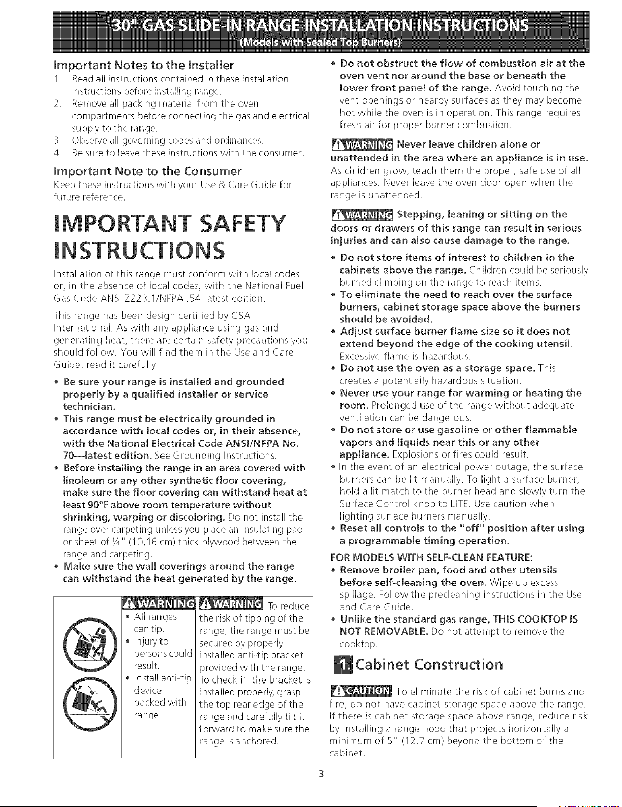
All ranges
can tip.
Injuryto
persons could
result.
Install anti4ip
device
packed with
range.
To reduce
the risk of tipping of the
range, the range must be
secured by properly
installed anti4ip bracket
provided with the range.
To check if the bracket is
installed properly, grasp
the top rear edge of the
range and carefully tilt it
forward to make sure the
range is anchored.
• Do not obstruct the flow of combustion air at the
oven vent nor around the base or beneath the
lower front panel of the range. Avoid touching the
vent openings or nearby surfaces as they may become
hot while the oven is in operation. This range requires
fresh air for proper burner combustion.
Never leave children alone or
unattended [n the area where an appliance [s [n use.
As children grow, teach them the proper, safe use of all
appliances. Never leave the oven door open when the
range is unattended.
Stepping, leaning or sitting on the
doors or drawers of this range can result in serious
injuries and can a[so cause damage to the range.
• Do not store items of interest to children in the
cabinets above the range. Children could be seriously
burned climbing on the range to reach items.
• To eJiminate the need to reach over the surface
burners, cabinet storage space above the burners
should be avoided.
Adjust surface burner flame size so it does not
extend beyond the edge of the cooking utensil.
Excessive flame is hazardous.
• Do not use the oven as a storage space. This
creates a potentially hazardous situation.
• Never use your range for warming or heating the
room. Prolonged use of the range without adequate
ventilation (:an be dangerous.
• Do not store or use gasoline or other flammable
vapors and liquids near this or any other
appliance. Explosions or fires could result.
In the event of an electrical power outage, the surface
burners can be lit manually. To light a surface burner,
hold a lit match to the burner head and slowly turn the
Surface Control knob to LITE. Use caution when
lighting surface burners manually.
Reset all controts to the "off" position after using
a programmable timing operation.
FOR MODELS WITH SELF-CLEAN FEATURE:
Remove broiler pan, food and other utensils
before self-cleaning the oven. Wipe up excess
spillage. Follow the precleaning instructions in the Use
and Care Guide.
• Unlike the standard gas range, THIS COOKTOP tS
NOT REMOVABLE. Do not attempt to remove the
cooktop.
Cabinet Construction
To eliminate the risk of cabinet burns and
fire, do not have cabinet storage space above the range.
If there is cabinet storage space above range, reduce risk
by installing a range hood that projects horizontally a
minimum of 5" (!2.7 cm) beyond the bottom of the
cabinet.
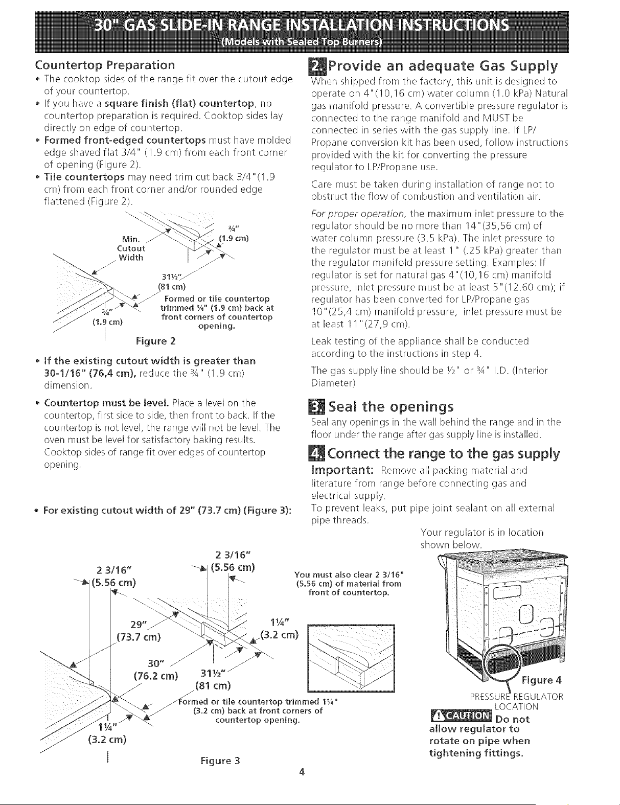
Countertop Preparation
• Tile cooktop sides of tile range fit over tile cutout edge
of your countertop.
• If you have a square finish (flat) countertop, no
countertop preparation is required. Cooktop sides lay
directly on edge of countertop.
Formed front-edged countertops must have molded
edge shaved flat 3/4" (1.9 cm) from each front comer
of opening (Figure 2).
• Tile countertops may need trim cut back 3/4"(1.9
cm) from each front corner and/or rounded edge
flattened (Figure 2).
(1.9cm)
J _J
311/_,,//
(81cm)
Formed or tile countertop
trimmed %" (1.9 cm) back at
front corners of countertop
(1.9 cm) opening.
[ Figure 2
• tf the existing cutout width is greater than
30-!/16" (76,4 cm), reduce the 3A" (!.9 cm)
dimension.
Provide an adequate Gas Supply
When shipped from the factory, this unit is designed to
operate on 4"(!0,!6 cm) water column (I .0 kPa) Natural
gas manifold pressure. A convertible pressure regulator is
connected to the range manifold and MUST be
connected in series with the gas supply line. If LP/
Propane conversion kit has been used, follow instructions
provided with tile kit for converting the pressure
regulator to LP/Propane use.
Care must be taken during installation of range not to
obstruct tile flow of combustion and ventilation air.
For praper operation, the maximum inlet pressure to tile
regulator should be no more than 14"(35,56 cm) of
water column pressure (3.5 kPa). The inlet pressure to
the regulator must be at least I " (.25 kPa) greater than
the regulator manifold pressure setting. Examples: If
regulator is set for natural gas 4"(10,16 cm) manifold
pressure, inlet pressure must be at least 5"(12.60 cm); if
regulator has been converted for LP/Propane gas
10"(25,4 cm) manifold pressure, inlet pressure must be
at least 11 "(27,9 cm).
Leak testing of the appliance shall be conducted
according to the instructions in step 4.
The gas supply line should be _/2" or ;A" I.D. (Interior
Diameter)
Countertop must be level. Place a level on the
countertop, first side to side, then front to back. If the
countertop is not level, the range will not be level. The
oven must be level for satisfactory baking results.
Cooktop sides of range fit over edges of countertop
opening.
For existing cutout width of 29" (73.7 cm) (Figure 3):
2 3/16"
(73.7 cm)
30" /
(76.2 cm)
(3.2 (m)
Seal the openings
Seal any openings in the wall behind the range and in the
floor under the range after gas supply line is installed.
Connect the range to the gas supply
Important: Remove all packing material and
literature from range before connecting gas and
electrical supply.
To prevent leaks, put pipe joint sealant on all external
pipe threads.
Your regulator is in location
shown below.
You must also clear 2 3/16"
(5.56 cm) of material from
front of countertop.
31W 'j
(81 cm)
./--
_Formed or tile countertop trimmed 11/4"
(3.2 cm) back at front corners of
countertop opening.
Figure 3
4
Figure 4
PRESSUR REGULATOR
LOCATION
Do not
aI[ow regulator to
rotate on pipe when
tightening fittings.
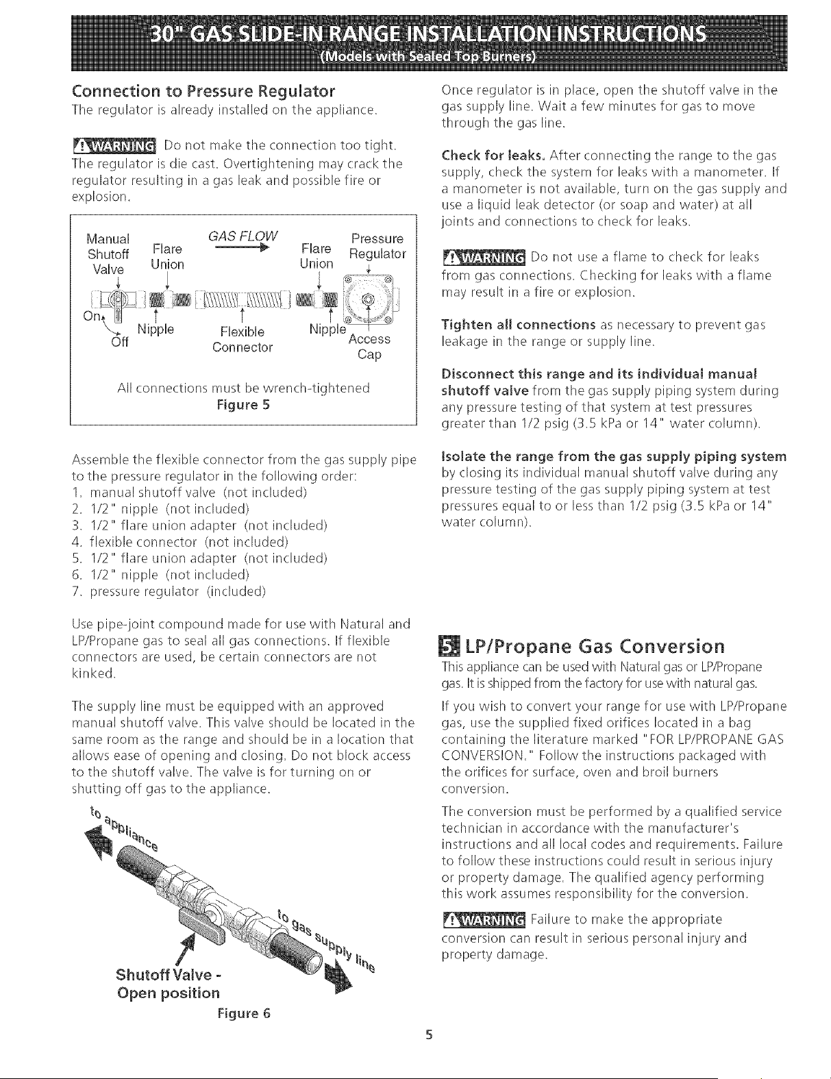
Connection to Pressure Regulator
The regulator is already installed on the appliance.
Do not make the connection too tight.
The regulator is die cast. Overtightening may (:rack the
regulator resulting in a gas leak and possible fire or
explosion.
Manual GAS FLOW Pressu re
Shutoff Flare _ Flare Regulator
Valve Union Union
_Off Nipple FlexBle NP_I '
Connector Access
Cap
All connections must be wrench4ightened
Figure 5
Once regulator is in place, open the shutoff valve in the
gas supply line. Wait a few minutes for gas to move
through the gas line.
Check for leaks. After connecting the range to the gas
supply, check the system for leaks with a manometer. If
a manometer is not available, turn on tile gas supply and
use a liquid leak detector (or soap and water) at all
joints and connections to check for leaks.
Do not use a flame to check for leaks
from gas connections. Checking for leaks with a flame
may result in a fire or explosion.
Tighten all connections as necessary to prevent gas
leakage in the range or supply line.
Disconnect this range and its individual manual
shutoff valve from the gas supply piping system during
any pressure testing of that system at test pressures
greater than 1/2 psig (3.5 kPa or 14" water column).
Assemble the flexible connector from the gas supply pipe
to the pressure regulator in the following order:
1. manual shutoff valve (not included)
2. 1/2" nipple (not included)
3. I/2" flare union adapter (not included)
4. flexible connector (not included)
5. 1/2" flare union adapter (not included)
6. 1/2" nipple (not included)
7. pressure regulator (included)
Isolate the range from the gas supply piping system
by (:losing its individual manual shutoff valve during any
pressure testing of tile gas supply piping system at test
pressures equal to or less than 1/2 psig (3.5 kPa or 14"
water column).
Use pipe-joint compound made for use with Natural and
LP/Propane gas to seal all gas connections. If flexible
connectors are used, be certain connectors are not
kinked.
The supply line must be equipped with an approved
manual shutoff valve. This valve should be located in the
same room as the range and should be in a location that
allows ease of opening and closing. Do not block access
to the shutoff valve. The valve is for turning on or
shutting off gas to the appliance.
t_
Shutoff Valve -
Open position
Figure 6
LP!Propane Gas Conversion
Thisappliance carl be used with Natural gas or LP/Propane
gas. It is shipped from the factory for use with natural gas.
If you wish to convert your range for use with LP/Propane
gas, use the supplied fixed orifices located in a bag
containing the literature marked "FOR LP/PROPANEGAS
CONVERSION." Follow the instructions packaged with
tile orifices for surface, oven and broil burners
conversion.
The conversion must be performed by a qualified service
technician in accordance with the manufacturer's
instructions and all local codes and requirements. Failure
to follow these instructions could result in serious injury
or property damage. The qualified agency performing
this work assumes responsibility for the conversion.
Failure to make the appropriate
conversion can result in serious personal injury and
property damage.
Electrical Requirements
120 volt, 60 Hertz, properly grounded dedicated circuit
protected by a 15 amp circuit breaker or time delay fuse.
Note: Not recommended to be installed with a Ground
Fault Interrupt (GFI).
Do not use an extension cord with this range.
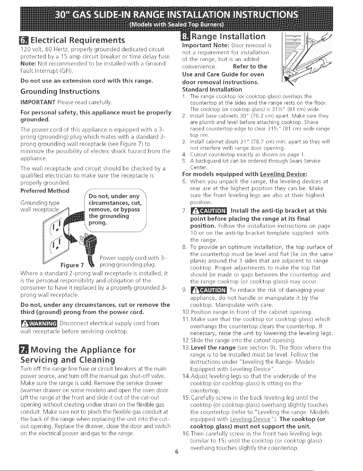
Grounding Instructions
IMPORTANT Please read carefully.
For personal safety, this appliance must be properly
grounded.
The power cord of this appliance is equipped with a 3-
prong (grounding) plug which mates with a standard 3-
prong grounding wall receptacle (see Figure 7) to
minimize tile possibility of electric shock hazard from the
appliance.
The wall receptacle and circuit should be checked by a
qualified electrician to make sure the receptacle is
properly grounded.
Preferred Method /_Do not, under anb/
Grounding type circumstances, cut,
wall rece remove, or bypas_
the grounding [
prong, /
Power supply cord with 3-
Figure 7 prong grounding plug.
Where a standard 2-prong wall receptacle is installed, it
is tile personal responsibility and obligation of the
consumer to have it replaced by a properly grounded 3-
prong wall receptacle.
Do not, under any circumstances, cut or remove the
third (ground) prong from the power cord.
Disconnect electrical supply cord from
wall receptacle before servicing cooktop.
Moving the Appliance for
Servicing and Cleaning
Turn off the range line fuse or circuit breakers at the main
power source, and turn off the manual gas shut-off valve.
Make sure the range is (:old. Remove the service drawer
(warmer drawer on some models) and open the oven door.
Lift the range at the front and slide it out of the cut-out
opening without creating undue strain on the flexible gas
conduit. Make sure not to pinch the flexible gas conduit at
the back of the range when replacing the unit into the cut-
out opening. Replace the drawer, close the door and switch
on the electrical power and gas to the range.
Range Installation
Important Note: Door removal is
not a requirement for installation
of the range, but is an added
convenience. Refer to the
Use and Care Guide for oven
door removal instructions.
Standard Installation
1.
The range cooktop (or cooktop glass) overlaps the
countertop at the sides and the range rests on the floor,
The cooktop (or cooktop glass) is 31_z" (81 cm) wide
2, Install base cabinets 30" (76_2 cm) apart Make sure they
are plumb and level before attachingcooktop Shave
raised countertop edge to clear 31_z" (81 cm) wide range
top rim
3, Install cabinet doors 31" (787cm) min apart so theywiJl
not interfere with range door opening_
4_ Cutout countertop exactly as shown on page 1
5. A backguard kit can be ordered through Sears Service
Center
For models equipped with Leveling Device:
6. When you unpack the range, the leveling devices at
rear are at the highest position they can be. Make
sure the front leveling legs are also at their highest
position.
7. _ Install the anti-tip bracket at this
point before placing the range at its fina[
position, Follow the installation instructions on page
10 or on the anti-tip bracket template supplied with
the range.
8. To provide an optimum installation, the top surface of
the countertop must be level and flat (lie on the same
plane) around the 3 sides that are adjacent to range
cooktop. Proper adjustments to make the top flat
should be made or gaps between the countertop and
the range cooktop (or cooktop glass) may occur.
9. _ To reduce the risk of damaging your
appliance, do not handle or manipulate it by the
cooktop. Manipulate with care.
10.Position range in front of the cabinet opening.
1 1.Make sure that the cooktop (or cooktop glass) which
overhangs the countertop clears the countertop. If
necessary, raise the unit by lowering the leveling legs.
12.Slide the range into the cutout opening.
13.Level the range (see section 9). The floor where the
range is to be installed must be level. Follow the
instructions under "Leveling the Range- Models
Equipped with Leveling Device".
14.Adjust leveling legs so that the underside of the
cooktop (or cooktop glass) is sitting on the
cou ntertop.
15.Carefully screw in the back leveling leg until the
cooktop (or cooktop glass) overhang slightly touches
the countertop (refer to "Leveling the range: Models
equipped with Leveling Device"). The cooktop (or
cooktop glass) must not support the unit,
16.Then carefully screw in the front two leveling legs
(similar to 15) until the cooktop (or cooktop glass)
overhang touches slightly the countertop.
For models equipped with Levelin Lg_:
6. To provide an optimum installation, the top surface of
the countertop must be level and flat (lie on the same
plane) around the 3 sides that are adjacent to range
cooktop. Proper adjustments to make the top flat
should be made or gaps between the countertop and
tile range cooktop (or cooktop glass) may occur.
7. _ To reduce tile risk of damaging your
appliance, do not handle or manipulate it by the
cooktop. Manipulate with care.
8. Position range in front of the cabinet opening.
9. Make sure that the cooktop (or cooktop glass) which
overhangs the countertop clears the countertop. If
necessary, raise the unit by lowering the leveling legs.
10.Level the range (see section 9). The floor where the
range is to be installed must be level. Follow the
instructions under "Leveling the Range-Models
Equipped with Leveling Legs".
11.Adjust leveling legs so that the underside of the
cooktop (or cooktop glass) is sitting on the
countertop.
12.Carefully screw in the back leveling leg until the
cooktop (or cooktop glass) overhang touches slightly
tile countertop. Tile cooktop must not support tile
unit.
13.Slide the range into the cutout opening.
14.Then carefully screw in tile front two leveling legs
(similar to 12) until the cooktop (or cooktop glass)
overhang touches slightly the countertop.
15.1f the range is not level, pull unit out and readjust
leveling legs, or make sure floor is level.
installation For 29" Existing Cutout Width Opening
1. You must replace tile original side panels with new
and thinner side panels. These new side panels can
be ordered through a Sears Service Center.
2. Follow instructions supplied with your new side
panels to replace tile original side panels with the
new ones.
3. Check if the countertop is prepared for 29" cutout
wide opening at page 3.
4. Install range as in tile "Standard Installation"
section above.
JnstaJJation With Backguard
A backguard kit can be ordered through a Sears Service
Center. The cutout depth (21 3/4" (55.2 cm) Min., 22 1/
8" (56.2 cm) Max.) needs to be increased to 24" (61
cm) when installing a backguard
installation With End Panel
An end panel kit can be ordered through a Sears Service
Center.
installation With Side Panel
A side panels kit can be ordered through a Sears Service
Center. Install cabinet doors 31 " (78.7 cm) rain. apart so
as not to interfere with range door opening.
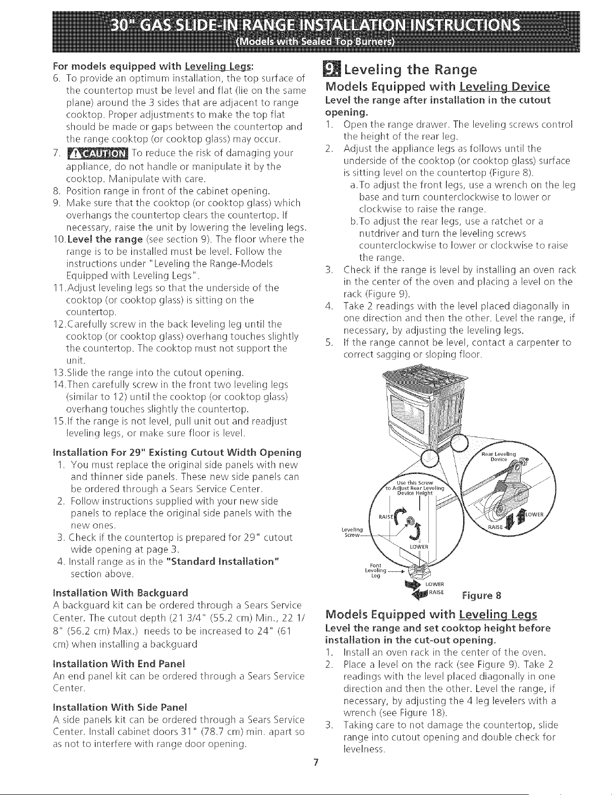
LeveJing the Range
Models Equipped with Leveling Device
Level the range after installation in the cutout
opening.
1. Open tile range drawer. The leveling screws control
the height of the rear leg.
2. Adjust the appliance legs as follows until the
underside of tile cooktop (or cooktop glass) surface
is sitting level on the countertop (Figure 8).
a.To adjust the front legs, use a wrench on the leg
base and turn counterclockwise to lower or
clockwise to raise tile range.
b.To adjust tile rear legs, use a ratchet or a
nutdriver and turn the leveling screws
counterclockwise to lower or clockwise to raise
the range.
3. Check if tile range is level by installing an oven rack
in the center of the oven and placing a level on tile
rack (Figure 9).
4. Take 2 readings with the level placed diagonally in
one direction and then the other. Level the range, if
necessary, by adjusting tile leveling legs.
5. If the range cannot be level, contact a carpenter to
correct sagging or sloping floor.
Leve_ing
Font
LevelR}g
Leg
LOWER
Figure 8
Models Equipped with Leveling Legs
Levet the range and set cooktop height before
installation in the cut-out opening.
1. Install an oven rack in the (.enter of tile oven.
2. Place a level on the rack (see Figure 9). Take 2
readings with the level placed diagonally in one
direction and then the other. Level the range, if
necessary, by adjusting the 4 leg levelers with a
wrench (see Figure 18).
3. Taking care to not damage tile countertop, slide
range into (.utout opening and double check for
levelness.
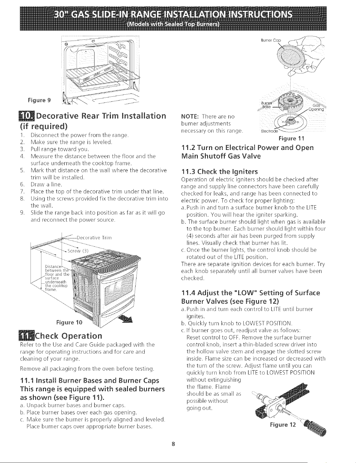
Figure9
Decorative Rear Trim JnstaINation
(if required)
1. Disconnect the power from the range.
2. Make sure the range is leveled.
3. Pull range toward you.
4. Measure the distance between the floor and the
surface underneath tile cooktop frame.
5. Mark that distance on tile wall where the decorative
trim will be installed.
6. Draw a line.
7. Place the top of the decorative trim under that line.
8. Using the screws provided fix the decorative trim into
tile wall.
9. Slide tile range back into position as far as it will go
and reconnect the power source.
Trim
Figure 10
Check Operation
Refer to the Use and Care Guide packaged with the
range for operating instructions and for care and
cleaning of your range.
Remove all packaging from the oven before testing.
11.1 install Burner Bases and Burner Caps
This range is equipped with sealed burners
as shown (see Figure 11}.
a. Unpack burner bases and burner caps.
b. Place burner bases over each gas opening.
c. Make sure the burner is properly aligned and leveled.
Place burner caps over appropriate burner bases.
NOTE: There are no
burner adjustments
necessary on this range. Eleotrod_-
Figure 11
11.2 Turn on Electrical Power and Open
Main Shutoff Gas Valve
11.3 Check the Igniters
Operation of electric igniters should be checked after
range and supply line connectors have been carefully
checked for leaks, and range has been connected to
electric: power. To check for proper lighting:
a. Push in and turn a surface burner knob to tile LITE
position. You will hear tile igniter sparking.
b. The surface burner should light when gas is available
to the top burner. Each burner should light within four
(4) seconds after air has been purged from supply
lines. Visually check that burner has lit.
c. Once the burner lights, the control knob should be
rotated out of the LITE position.
There are separate ignition devices for each burner. Try
each knob separately until all burner valves have been
checked.
11,4 Adjust the "LOW" Setting of Surface
Burner Valves (see Figure 12)
a. Push in and turn each control to LITE until burner
ignites.
b. Quickly turn knob to LOWEST POSITION.
c. If burner goes out, readjust valve as follows:
Reset control to OFF. Remove the surface burner
control knob, insert a thin-bladed screw driver into
the hollow valve stem and engage the slotted screw
inside. Flame size can be increased or decreased with
the turn of the screw. Adjust flame until you can
quickly turn knob from LITEto LOWEST POSITION
without extinguishing
the flame. Flame
should be as small as
possible without
going out.
Figure 12
11.5 Operation of Oven Burners and Oven
Adjustments
1!.5.1 Etectric ignition Burners
Operation of electric igniters should be checked after
range and supply line connectors have been carefully
checked for leaks, and range has been connected to
electric power.
The oven burner is equipped with an electric control
system as well as an electric oven burner igniter. If your
model is equipped with a waist-high broil burner igniter, it
will also have an electric: burner igniter. These control
systems require no adjustment. When the oven is set to
operate, current will flow to the igniter. It will "'glow"'
similar to a light bulb. When the igniter has reached a
temperature sufficient to ignite gas, the electrically
controlled oven valve will open and flame will appear at
the oven burner. There is a time lapse from 30 to 60
seconds after thermostat is turned ON before the flame
appears at the oven burner. When the oven reaches the
display setting, the glowing igniter will go off. The burner
flame will go "'out"' in 20 to 30 seconds after igniter goes
"'OFF"'.To maintain any given oven temperature, this
cycle will continue as long as the display is set to operate.
After removing all packing materials and literature from
the oven:
a) Set the oven to BAKE at 300°F. See Use & Care Guide
for operating instructions.
b) Within 60 seconds the oven burner should ignite.
Check for proper flame, and allow the burner to cycle
once. Reset controls to off.
c) If your model is equipped with a high-waist broiler, set
oven to broil. See Use & Care Guide for operating
instructions.
d) Within 60 seconds tile broil burner should ignite. Check
for proper flame. Resetcontrols to off.
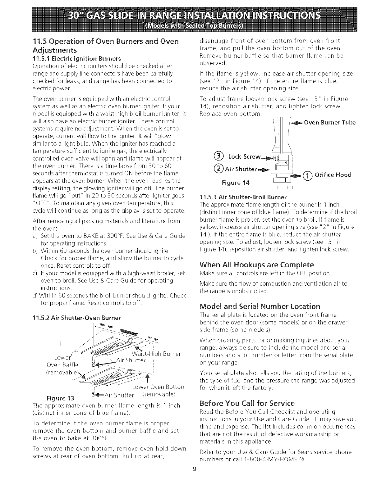
....
L wer _ gh Burner
I
Oven Baffle i
(removable
Figure 13
Tile approximate oven burner flame length is 1 inch
(distinct inner cone of blue flame).
To determine if tile oven burner flame is proper,
remove tile oven bottom and burner baffle and set
the oven to bake at 300%.
Lower Oven Bottom
_---Ai r Shutter (removable)
To remove the oven bottom, remove oven hold down
screws at rear of oven bottom. Pull up at rear,
disengage front of oven bottom from oven front
frame, and pull tile oven bottom out of tile oven.
Remove burner baffle so that burner flame can be
observed.
If the flame is yellow, increase air shutter opening size
(see "2" in Figure 14). If the entire flame is blue,
reduce the air shutter opening size.
To adjust frame loosen lock screw (see "'3"' in Figure
14), reposition air shutter, and tighten lock screw.
Replace oven bottom.
/ Oven Burner Tube
I
Lock Screw_4_rr_ /_
! 1,5,3 Air Shutter-Broil Burner
The approximate flame length of the burner is 1 inch
(distinct inner cone of blue flame). To determine if the broil
burner flame is proper, set the oven to broil. If flame is
yellow, increase air shutter opening size (see "2" in Figure
14). If tile entire flame is blue, reduce tile air shutter
opening size. To adiust, loosen lock screw (see "3" in
Figure 14), reposition air shutter, and tighten lock screw.
When All Hookups are Complete
Make sure all controls are left in the OFFposition.
Make sure the flow of combustion and ventilation air to
the range is unobstructed.
Model and Serial Number Location
The serial plate is located on tile oven front frame
behind the oven door (some models or on the drawer
side frame (some models).
When ordering parts for or making inquiries about your
range, always be sure to include the model and serial
numbers and a lot number or letter from tile serial plate
on your range.
Your serial plate also tells you the rating of tile burners,
the type of fuel and the pressure the range was adjusted
for when it left the factory.
Before You Call for Service
Read the Before You Call Checklist and operating
instructions in your Use and Care Guide. It may save you
time and expense. The list includes common occurrences
that are not tile result of defective workmanship or
materials in this appliance.
Refer to your Use & Care Guide for Sears service phone
numbers or call 1-800-4-MY-HOME @.
Anti-Tip Brackets JnstaJJation
instructions
ModeJs Equipped with LeveJing Device
To reduce the risk of tipping of the range,
the range must be secured to the floor by properly installed
anti-tip bracket and screws packed with tile range. These
parts are located in the oven. Failure to install the anti-tip
bracket will allow tile range to tip over if excessive weight
is placed on an open door or if a child climbs upon it.
Serious injury might result from spilled hot liquids or from
the range itself.
Follow the instructions below to install the anti-tip
brackets.
If range is ever moved to a different location, the anti-tip
brackets must also be moved and installed with the
range.
Tools Required:
Adjustable Wrench
Ratchet
Drill & 1/8"(0,32 cm) bit
5/16" (0,8 cm) Nutdriver
Level
The anti-tip bracket attaches to the floor at the back of the
range to prevent range from tipping. When fastening
bracket to the floor, be sure that screws do not penetrate
electrical wiring or plumbing. The screws provided will
work in either wood or concrete.
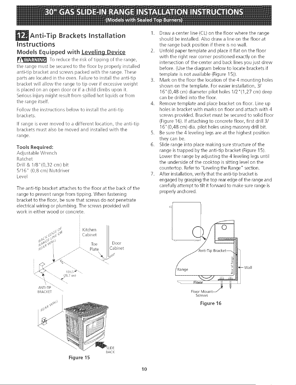
1. Draw a center line (CL) on the floor where the range
should be installed. Also draw a line on the floor at
the range back position if there is no wall.
2. Unfold paper template and place it flat on the floor
with the right rear corner positioned exactly on the
intersection of the center and back lines you just drew
before. (Use the diagram below to locate brackets if
template is not available (Figure 15)).
3. Mark on the floor the location of the 4 mounting holes
shown on the template. For easier installation, 3/
16"(0,48 cm) diameter pilot holes 1/2"(1,27 cm) deep
can be drilled into the floor.
4. Remove template and place bracket on floor. Line up
holes in bracket with marks on floor and attach with 4
screws provided. Bracket must be secured to solid floor
(Figure 16). If attaching to concrete floor, first drill 3/
16"(0,48 cm) dia. pilot holes using masonry drill bit.
5. Be sure the 4 leveling legs are at the highest position
they can be.
6. Slide range into place making sure structure of the
range is trapped by the anti-tip bracket (Figure 15).
Lower the range by adjusting the 4 leveling legs until
the underside of the cooktop is sitting level on the
countertop. Refer to "Leveling the Range" section.
7. After installation, verify that the anti-tip bracket is
engaged by grasping the top rear edge of the range and
carefully attempt to tilt it forward to make sure range is
properly anchored.
Kitchen
Cabinet
DOOr
Cabinet
Wait
Screws
Figure 16
BACK
Figure 15
10
ModeBsEquipped with LeveB[ng[eBegs
Toreducetheriskoftippingof therange,
tile rangemustbesecuredto thefloorbyproperly
installedanti-tipbracketsandscrewspackedwith the
range.Thesepartsarelocatedin a plastic:bagin the
oven.Failureto installtheantPtipbracketswill allowthe
rangeto tip overif excessiveweightisplacedonan
opendoororif achildclimbsuponit. Seriousinjury
mightresultfromspilledhot liquidsorfromtherange
itself.
Followtheinstructionsbelowto installtheantPtip
brackets.
If rangeisevermovedto adifferentlocation,theantPtip
bracketsmustalsobemovedandinstalledwith the
range.Tocheckfor properinstallation,seestep5.
ToolsRequired:
5/16"(0,79cm)Nutdriveror FlatHeadScrewdriver
AdjustableWrench
ElectricDrill
3/16"(0,5cm)DiameterDrillBit
3/16"(0,5cm)DiameterMasonryDrillBit(if installingin
concrete)
Bracketsattachto the floorat tile backof tile rangeto
holdbothrearleglevelers.Whenfasteningto thefloor,
besurethatscrewsdo notpenetrateelectricalwiringor
plumbing.Thescrewsprovidedwillworkineitherwood
orconcrete.
AntPtip Bracket
Back Edge of Range ¢
or Rear Wall "<_ _._.....
...-9us"_... 18w'>\ ._'-.
'<:"/\'-.. 28 !/8"
AntPtip Bracket ""--. (71.4cm)
"-.#/(Rear width of range
with body sides)
(eL = Center line)
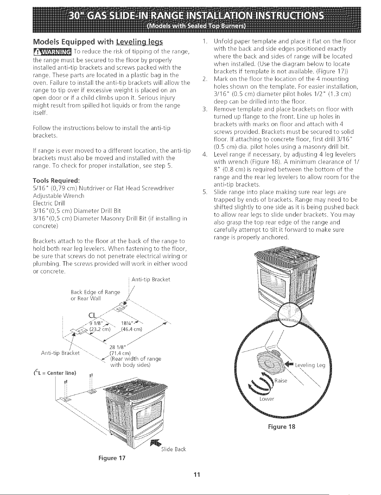
1. Unfold paper template and place it flat on the floor
with the back and side edges positioned exactly
where the back and sides of range will be located
when installed. (Use the diagram below to locate
brackets if template is not available. (Figure 17))
2. Mark on the floor the location of the 4 mounting
holes shown on the template. For easier installation,
3116" (0.5 cm) diameter pilot holes 1/2" (1.3 cm)
deep can be drilled into the floor.
3. Remove template and place brackets on floor with
turned up flange to tile front. Line up holes in
brackets with marks on floor and attach with 4
screws provided. Brackets must be secured to solid
floor. If attaching to concrete floor, first drill 3/16"
(0.5 cm) dia. pilot holes using a masonry drill bit.
4. Level range if necessary, by adjusting 4 leg levelers
with wrench (Figure 18). A minimum clearance of I/
8" (0.8 cm) is required between the bottom of the
range and the rear leg levelers to allow room for the
antPtip brackets.
5. Slide range into place making sure rear legs are
trapped by' ends of brackets. Range may' need to be
shifted slightly to one side as it is being pushed back
to allow rear legs to slide under brackets. You may
also grasp the top rear edge of the range and
carefully attempt to tilt it forward to make sure
range is properly anchored.
Figure 18
Figure 17
Slide Back
11
LA mNSTALAaON Y EL SERVmaO DEBEN SER EFECTUADOS POR UN mNSTALADOR
CAURCADO. mMPORTANTE: GUARDE ESTAS mNSTRUCaONES PARA USO DEL INSPECTOR LOCAL
DE ELECTRmaDAD. LEA Y GUARDE ESTAS mNSTRUCaONES PARA REFERENaA FUTURA.
Si [a information contenida en este manual no es seguida exactamente,
puede ocurrir un incendio o explosi6n causando daffos materiales, lesi6n personal o la
muerte.
PARA SU SEGURDAD:
-- No aImacene ni utilke gasolina u otros vapores y [iquidos inflamables en la proximidad
de _ste o de cuaIquier otto artefacto.
-- QUE DEBE HACER SmPERaBE OLOR A GAS:
No trate de encender ningQn artefacto.
No toque ningun interruptor el&ctrico; no use ningQn tel_fono en su edificio.
Llame a su proveedor de gas desde el te[_fono de un vecino. Siga [as instrucciones de[
proveedor de gas,
Si no [ogra comunicarse con su proveedor de gas, [lame a[ departarnento de bomberos.
-- La insta[adon y el servido de mantenim[ento deben set efectuados pot un [nsta[ador
ca[ffkado, [a agenda de servkb o el proveedor de gas.
Aparatos Jnsta[ados en el
estado de Massachusetts;
Este Aparato solo puede ser
instalado en el estado de
Massachusetts pot un plornero
o ajustador de gas licenciado
de Massachusett
Este aparato se debe insta[ar
con un largo conector flexible
de gas de tres (3) pies!36
pulgadas
Una va'[vu[a manual de gas de
tipo rnanija de forrna de "T" se
debe insta[ar en [a [[nea de[
surninistro de gas de este
aparato,
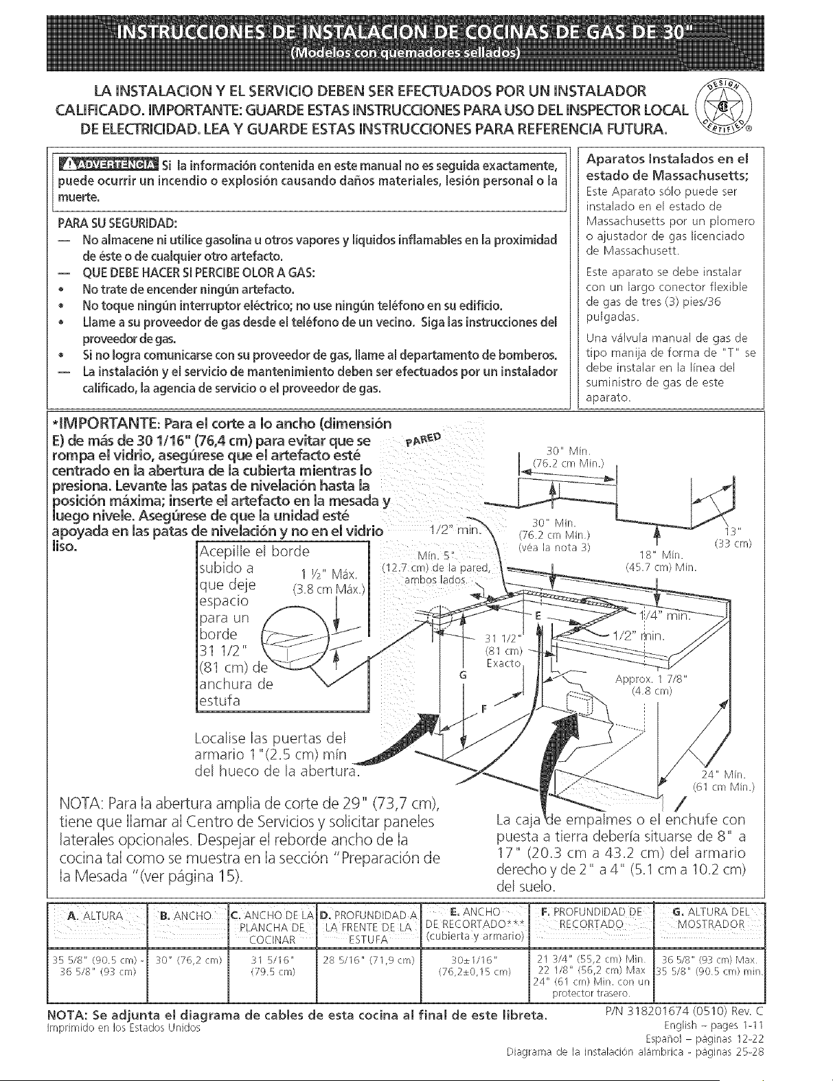
*IMPORTANTE: Para el torte a 1o ancho (dimensi6n
E) de rn=is de 301/16" (76,4 cm) para evitar que se _ggg_
rompa el vidrio, asegQrese que el artefacto este
centrado en [a abertura de [a cubierta mientras 1o
presiona. Levante [as patas de niveiad6n hasta [a
posid6n maxima; inserte el artefacto en la mesada y
luego nivele. Asegurese de que la unidad este
apoyada en las patas de niveladon y no en el vidrio
liso, Acepille el borde
(12.7 cm) de la
subido a 1 Y2" Mc_x. ambos lados.
que de]e (Z8cm b1_Sxj
espacio
para un
horde
31 1/2"
(81 cm)
anchura de
estufa
(yea [a nota 3)
I3"
(33 cm)
Localise [as puertas de[
armario 1 "(2.5 cm) rain
del hueco de la abertura7
NOTA: Para Ia abertura amplia de corte de 29" (73,7 cm),
tiene que Ilamar aI Centro de Servicios y soticitar paneles La caja
24" Min.
(61 cm Min.)
-1 /
palmes o el enchufe con
laterales opcionales. Despejar el reborde ancho de Ia
cocina tal como se muestra en Ia section "Preparaci6n de
Ia Mesada "(vet p_igina 15).
A. ALTURA
c:Ar,,,JcnoDEI_)
DI PROFUNDIDAD A
puesta a tierra deber[a situarse de 8" a
17" (20.3 cm a 43.2 cm) del armario
derecho y de 2" a 4" (5.1 cm a 102 cm)
del suelo.
E ANCHO
ALTURA DEL
35 5/8" (905 cm) - 30" (76,2 cm) 31 5/16" 28 5/16" (71,9 cm) 30±1/16" 21 3/4" (55,2 cm) Min 36 5/8" (93 cm) Max
:_6 5/8" (9:_cm} (795cm) (76,2±0,I5cm) 22 118" (56,2 era) Max :_B 5/8" (905cm) min
24" (61 cm) Min. con un
protector trasero
NOTA: Se adjunta el diagrama de cables de esta cocina aJ final de este Jibreta. P/N 318201674 (0510) Rev. C
Imprimido en los Estados Unidos English - pages 1-I 1
Espanol - paginas I2-22
Diagrama de la instalacion alambrica - paginas 25-28
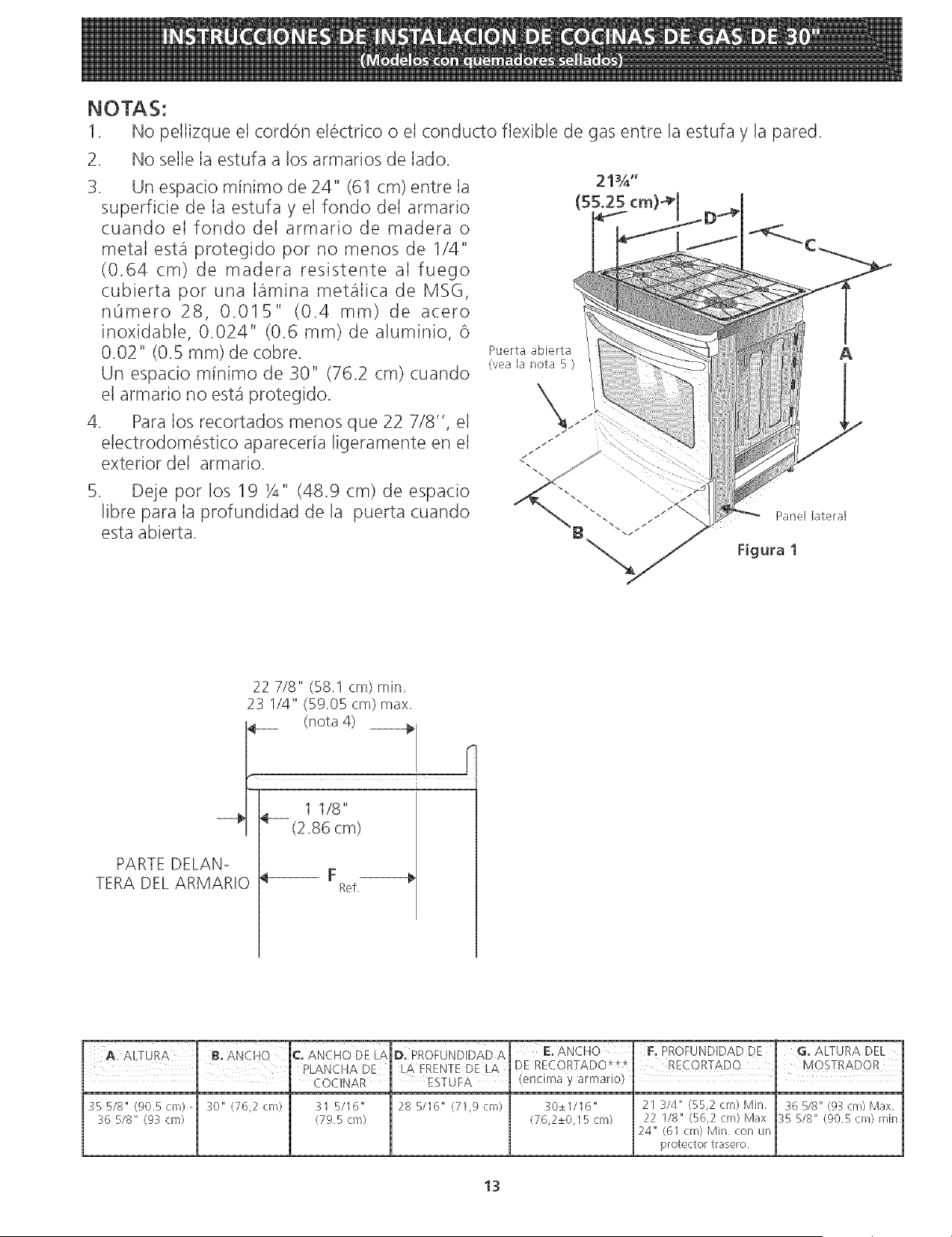
NOTAS:
1. No pellizque el cord6n el_ctrico o el conducto flexible de gas entre la estufa y la pared.
No selIe Ia estufa a los armarios de Iado.
3. Un espacio minimo de 24" (61 cm) entre Ia
superficie de Ia estufa y el fondo deI armario
cuando el fondo deI armario de madera o
metal est,1 protegido pot no menos de 1/4"
(0.64 cm) de madera resistente aI fuego
cubierta pot una lamina met_ilica de MSG,
nOmero 28, 0.015" (0.4 ram) de acero
inoxidable, 0.024" (0.6 ram) de aluminio, 6
0.02" (0.5 ram) de cobre.
Un espacio minimo de 30" (762 cm) cuando
el armario no est,1 protegido.
4. Para los recortados menos que 22 7/8", el
electrodom6stico apareceria ligeramente en el
exterior del armario.
Deje pot los 19 Y4" (48.g cm) de espacio
libre para Ia profundidad de la puerta cuando
esta abierta.
Puerta abierta
(yea la nota 5 )
A
Panel lateral
Figura 1
PARTE DELANo
TERA DEL ARMARIO
22 7/8" (58.1 cm) rain.
23 I/4" (59.05 cm) max.
(nota 4)
1 118"
(2.86 cm)
Ref.
E, ANCHO F, PROFUNDIDAD DE , G, ALTURA DEL
i DE RECORTADO* * RECORTADO ' MOSTRADOR
(encima y armario) ' l
30±1/16" 21 3/4" (55,2 cm) Min. 36 5/8" @3 cm) Max,
:_6 5/8" (9:_ cm) (795 cm) (76,2±0,15 cm) 22 118" (56,2 cm) Max :_5 B/8" (905 cm) rnir/
24" (61 cm) Min con un
protector trasero
13
Notas importantes para e[ [nsta[ador
1. Lea todas las instrucciones contenidas en este manual
antes de instalar la estufa.
2. Saque todo el material usado en e! embalaje del
compartimiento de! homo antes de conectar el
suministro electrico o de gas a la estufa.
3, Observe todos los cOdigos y reglamentos pertinentes.
4, Deje estas instrucciones con el comprador.
Nota Importante para el Consumidor
Conserve estas instrucciones y el Manual del Usuario para
referencia futura.
IMPORTANTES
INSTRUCCIONI=S DI=
SI=GURIDAD
Instalaci6n de esta estufa debe cumplir con todos los
c6digos locales, o en ausencia de cOdigos locales con el
COdigo Nacional de Gas Combustible ANSI Z223.1/NFPA
.54--01tima ediciOn,
E! diseflo de esta estufa ha sido certificado por la CSA
Internacional. En este como en cualquier otto artefacto
que use gas y genere calor, hay ciertas precauciones de
seguridad que usted debe seguir. Estas ser_in encontradas
en el Manual de! Usuario, lealo cuidadosamente.
AsegQrese de que la estufa sea instalada y
conectada a tierra en forma apropiada por un
instalador calificado o pot un tecnico.
• Esta estufa debe set eJ(_ctricamente puesta a tierra
de acuerdo con los c6digos locales, o en su
ausenda, con el C6digo Electrico National ANSI/
NFPA No. 70, ultima edici6n. Vea las instrucciones
para la puesta a tierra en la p_igina 4.
• Antes de instalar la estufa en un _rea cuyo piso
este recubierto con linbleo u otro tipo de piso
sintetico, asegurese de que _stos puedan resistir
una temperatura de por Io menos 90°F sobre Ja
temperatura ambiental sin provocar encogimiento,
deformaci6n o decomoradon. No instale laestufa
sobre una alfombra al menos que coloque una plancha
de material aislante de por Io menos 1/4 pulgada,
entre la estufa y la alfombra.
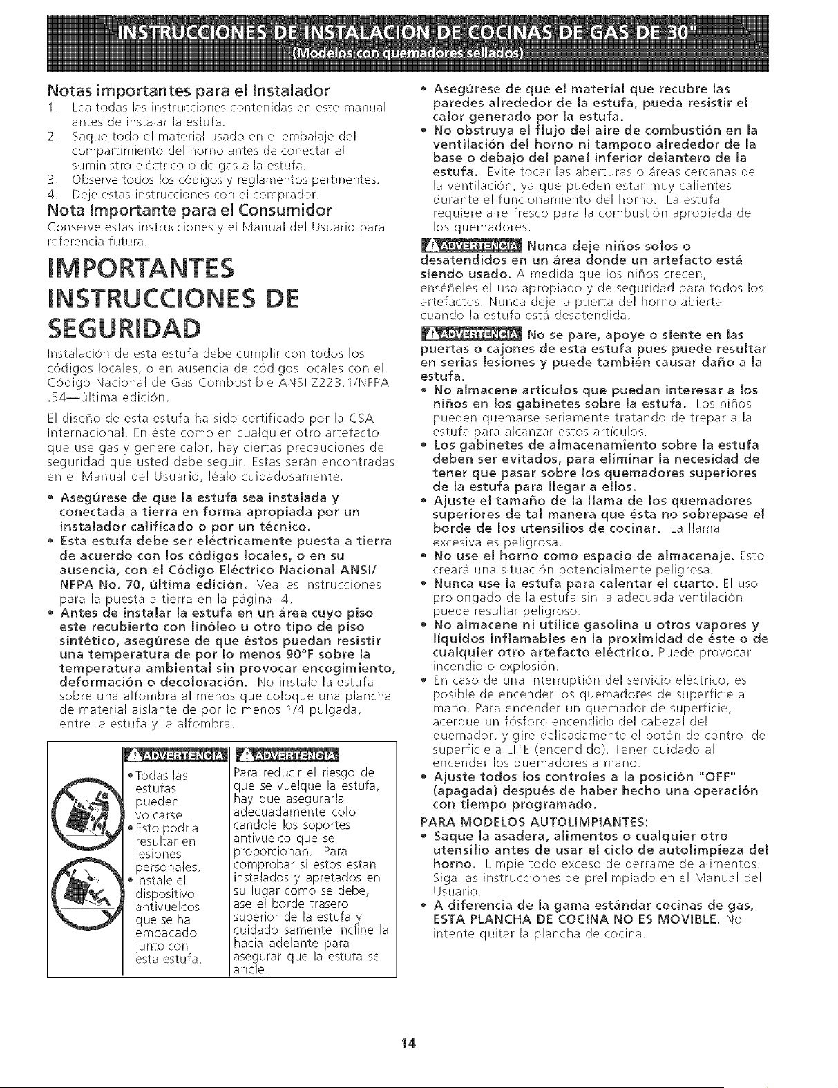
F cge 1 'tr4
• Todas las
estufas
pueden
I volcarse.
Esto podria
resultar en
lesiones
personales,
®Instale el
d ispositivo
antivuelcos
que se ha
empacado
junto con
esta estufa.
Para reducir el riesgo de
que se vuelque la estufa,
hay que asegurarla
adecuadamente co!o
candole los soportes
antivuelco que se
proporcionan. Para
comprobar si estos estan
instalados y apretados en
su lugar como se debe,
ase el borde trasero
superior de la estufa y
cuidado samente incline la
hacia adelante para
asegurar que la estufa se
ancle.
• AsegQrese de que el material que recubre [as
paredes alrededor de [a estufa, pueda resistir el
calor generado pot [a estufa.
• No obstruya eJ flujo dem aire de combustibn en la
ventilation dem homo ni tampoco alrededor de Ja
base o debajo del panel inferior delantero de Ja
estufa. Evite tocar las aberturaso a'reascercanas de
la ventilaci6n, ya que pueden estar muy calientes
duranteelfuncionamientodel homo. Laestufa
requiere aire fresco para la combustion apropiada de
los quemadores.
Nunca deje ni_os solos o
desatendidos en un Mea donde un artefacto est_
siendo usado. A medida que los niCios crecen,
ens6F_eles el uso apropiado y de seguridad para todos los
artefactos. Nunca deje la puerta del homo abierta
cuando la estufa est,1 desatendida.
No se pare, apoye o siente en [as
puertas o cajones de esta estufa pues puede resuJtar
en serias Jesiones y puede tambien causar da5o a Ja
estufa.
,, No almacene articuJos que puedan interesar a los
ni_os en los gabinetes sobre Ja estufa. Los niF_os
pueden quemarse seriamente tratando de trepar a la
estufa para alcanzar estos articulos.
,, Los gabinetes de aJmacenamiento sobre Ja estufa
deben set evitados, para elirninar [a necesidad de
tenet que pasar sobre los quemadores superiores
de Ja estufa para JJegar a eJJos.
• Ajuste el tamaSo de Ja llama de los quemadores
superiores de tal manera que esta no sobrepase el
bordede los utensiJiosdecocinar. La llama
excesiva es peligrosa.
No use el homo como espacio de almacenaje. Esto
crear3 una situaci6n potencialmente peligrosa.
• Nunca use la estufa para caJentar el cuarto. E! uso
prolongado de la estufa sin la adecuada ventilaciOn
puede resultar peligroso.
• No almacene ni utilice gasolina u otros vapores y
Jiquidos inflarnables en la proximidad de este o de
cualquier otto artefacto eJectrico. Puede provocar
incendio o exp!osi6n.
• En caso de una interrupti6n del servicio e!#ctrico, es
posible de encender los quemadores de superficie a
mano. Para encender un quemador de superficie,
acerque un f6sforo encendido del cabezal del
quemador, y gire delicadamente e! bot6n de control de
superficie a LITE (encendido). Tener cuidado al
encender los quemadores a mano,
• Ajuste todos los controJes a la posidbn "OFF"
(apagada) despues de haber hecho una operacion
con tiempo programado.
PARA MODELOS AUTOLIMPIANTES:
,, Saque la asadera, alimentos o cualquier otro
utensiJio antes de usar el ddo de autolimpieza del
homo. Limpietodoexcesode derrame dealimentos.
Siga las instrucciones de prelimpiado en e! Manual del
Usuario.
, A diferenda de Ja gama est&ndar codnas de gas,
ESTA PLANCHA DE COCJNA NO ES MOVIBLE. No
intente quitar la plancha de cocina.
14
Construction del armario
r.__ Para eliminar el riesgo de quemaduras o
de fuego tratando de alcanzar algo por encima de las
zonas calientes, evite de colocar articulos sobre la cocina.
Si cree necesitar este espacio, el riesgo puede disminuir si
instala un sombrerete que proteia horizontalmente un
minimo de 5" (12.7cm) sobre la base del armario.
Preparad6n del mostrador
• Las extremidades de la cocina sobrepasan el borde de
su mostrador.
Si tiene un mostrador con tas extremidades
cuadradas (planas), no se necesita ninguna
preparaci6n del mostrador.
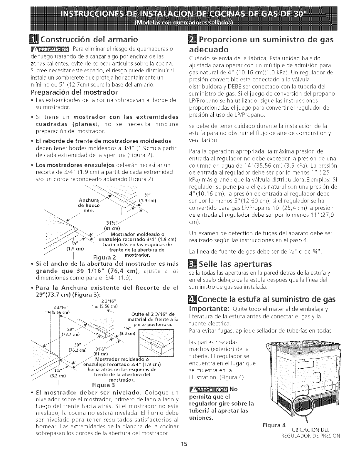
• E[ reborde de frente de mostradores moJdeados
deben tener hordes moldeados a 3/4" (1.9cm) a partir
de cada extremidad de la apertura (Figura 2).
Los mostradores enazuJejos deber_n necesitar un
recorte de 3/4" (1.9 cm) a partit de cada extremidad
y/o un horde redondeado aplanado (Figura 2).
Anchur_
de hueco
(1.9cm)
311/2'_
(81cm)
/ Mostrador moldeado o
enazulejo recortado 3/4" (1.9 era)
hada arras en las esquinas de
(1.9 cm) frente de la abertura de[
Figura 2
mostrador,
Si e[ ancho de [a abertura de[ mostrador es m&s
grande que 30 1/16" (76,4 cm), ajuste a las
dimensiones como para el 3/4" (1.9).
• Para [a Anchura existente de[ Recorte de e[
29"(73.7 cm} (F[gura 3):
2 3116"
2 3/16" (5.56 era)
-_(5,56 cm)
i
Quite e[ 2 3/16" de
material de frente a [a
parte posteriora.
11/4"
,,jo recortado 3/4" (1.9 cm)
hacia atr_s en las esquinas de
(3,2 cm) frente de la abertura de[
mostrador.
[ Figura 3
• E[ mostrador deber set hive[ado. Coloque un
nivelador sobre el mostrador, primero de lado a lado y
luego del frente hacia atr_s. Si el mostrador no estg
nivelado, la cocina no estar& nivelada. El homo debe
ser nivelado para tener resultados satisfactorios al
hornear. Las extremidades de la plancha de la cocinar
sobrepasan los hordes de la abertura del mostrador.
Proporcione un suministro de gas
adecuado
Cu_ndo se env[a de la fabrica, Esta unidad ha sido
ajustada para operar con un mOltiple de admision para
gas natural de 4" (!0.16 cm)(!.0 kPa). Un regulador de
presion convertible esta conectado a la v&lvula
distribuidora y DEBE ser conectado con la tuberia del
suministro de gas. 5i eljuego de conversion del propano
LP/Propano se ha utilizado, sigue las instrucciones
proporcionadas el juego para convertir el regulador de
presion al uso de LP/Propano.
se debe de tener cuidado durante la instalaci()n de la
estufa para no obstruir el flujo de aire de combustion y
ventilaci6n
Para la operacion apropriada, la maxima presion de
entrada al regulador no debe execeder la presion de una
columna de agua de 14"(35,56 cm) (3.5 kPa). La presion
de entrada al regulador debe ser por Io menos I " (.25
kPa) m_s grande que la v_lvula distribuidora.Eiemplos: Si
regulador se pone para el gas natural con una presion de
4"(10,16 cm), la presi6n de entrada al regulador debe
ser por Io menos 5"(!2.60 cm); si el regulador se ha
convertido para gas LP/Propane 10"(25,4 cm)la presion
de entrada al regulador debe ser pot Io menos 11 "(27,9
cm),
Un examen de detection de fugas del aparato debe ser
realizado segOn las instrucciones en el paso 4.
La linea de fuente de gas debe ser de Y2" o de sA".
Selle las aperturas
sella todas las aperturas en la pared detras de la estufa y
en el suelo debajo de la estufa despues que la linea del
suministro de gas sea instalada.
L l Conecte la estufa at suministro de gas
Importante: Quite todo el material de embalaje y
literatura de la estufa antes de conectar el gas y la
fuente electrica.
Para evitar fugas, aplique sellador de tuberias en todas
las partes roscadas
machos (exterior) de la
tuberia. El regulador se
encuentra en el lugar que
se muestra en la
illustration, (Figura 4)
15
perm[ta que el
regulador g[re sobre la
tuberi& at apretar tas
un[ones.
Figura 4
UBICACION DEL
REGULADOR DE PRESION
Conecte el Regulador de PresiOn
El regulador de presiOn esta ya instalada para la estufa.
W.__ No haga la conexiOn demasiado
apretada, El regulador es de die cast. El apretar
demasiado puede agrietar el regulador dando per
resultado una fuga de gas y un fuego o una explosion,
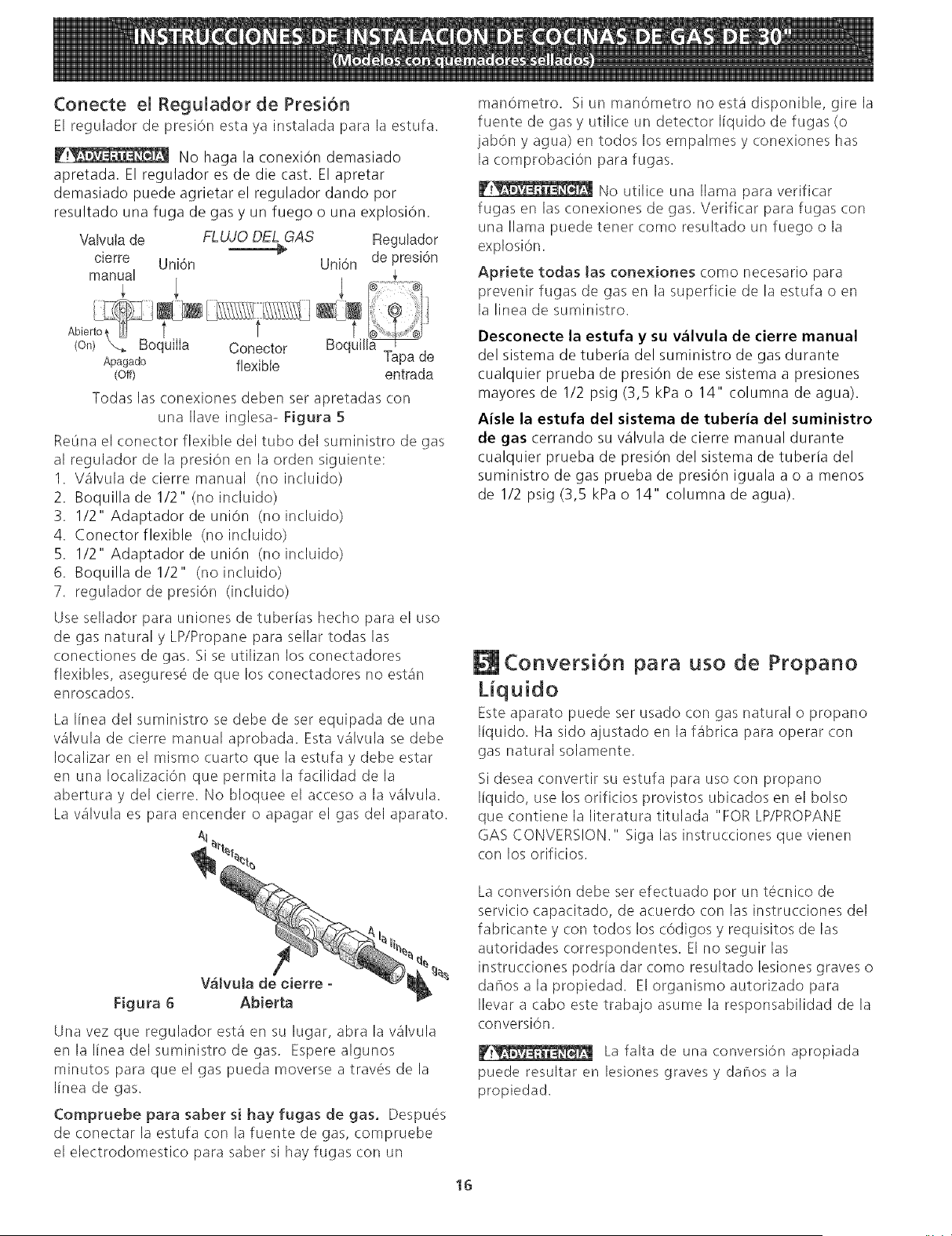
Vatvula de FLUJO DEL GAS Regutador
_ de presi6n
cierre Uni6n Uni6n
manuat
(on) _ BoquilIa Conector uitt
Apagado flexible Tapa de
(Off) entrada
Todas las conexiones deben set apretadas con
una Ilave inglesa- Figura 5
ReOna el conector flexible del tubo del suministro de gas
al regulador de la presiOn en la orden siguiente:
1. Valvuladecierremanual (noincluido)
2. Boquilla de 1/2" (no incluido)
3. 1/2" Adaptador de union (no incluido)
4. Conectorflexible (no incluido)
5. 1/2" Adaptador de union (no incluido)
6. Boquilladel/2" (noincluido)
7. regulador de presiOn (incluido)
Use sellador para uniones de tuberias hecho para el use
de gas natural y LP/Propane para sellar todas las
conectiones de gas. Si se utilizan los conectadores
flexibles, asegurese de que los conectadores no est&n
enroscados,
La linea del suministro se debe de ser equipada de una
valvula de cierre manual aprobada. Esta valvula se debe
Iocalizar en el mismo cuarto que la estufa y debe estar
en una Iocalizaci6n que permita la facilidad de la
abertura y del cierre. No bloquee el acceso a la valvula.
La valvula es para encender o apagar el gas del aparato.
manometro, Siunmanometronoestadisponible, girela
fuente de gas y utilice un detector liquido de fugas (o
jabOn y agua) en todos los empalmes y conexiones has
la comprobaciOn para fugas,
W!_ No utilice una llama para verificar
fugas en las conexiones de gas. Verificar para fugas con
una llama puede tenet come resultado un fuego o la
explosi6n.
Apriete todas las conexiones como necesario para
prevenir fugas de gas en la superficie de la estufa o en
la linea de suministro.
Desconecte la estufa y su v_lvula de cierre manual
del sistema de tuberia del suministro de gas durante
cualquier prueba de presiOn de ese sistema a presiones
mayores de 1/2 psig (3,5 kPa o 14" columna de agua),
Aisle la estufa del sistema de tuberia del suministro
de gas cerrando su valvula de cierre manual durante
cualquier prueba de presiOn del sistema de tuberia del
suministro de gas prueba de presiOn iguala a o a menos
de 1/2 psig (3,5 kPa o 14" columna de agua).
Conversion para uso de Propano
Liquido
Este aparato puede ser usado con gas natural o propano
I[quido. Ha sido ajustado en la %brica para operar con
gas natural solamente.
Si desea convertir su estufa para uso con propano
I[quido, use los orificios provistos ubicados en el bolso
que contiene la literatura titulada "FOR LP/PROPANE
GAS CONVERSION." Siga las instrucciones que vienen
con los orificios.
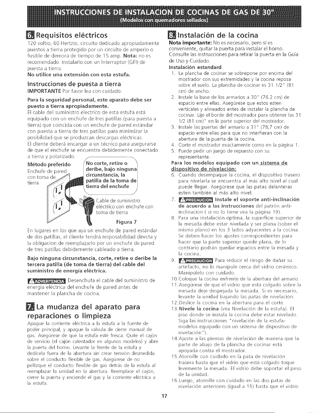
Figura 6 Abierta
Una vez que regulador esta en su lugar, abra la v_lvula
enlallneadelsuministrodegas. Esperealgunos
minutos para que el gas pueda moverse a travOs de la
Ilnea de gas.
Compruebeparasabersihayfugasdegas. Despues
de conectar la estufa con la fuente de gas, compruebe
el electrodomestico para saber si hay fugas con un
La conversi6n debe ser efectuado por un tecnico de
servicio capacitado, de acuerdo con las instrucciones del
fabricante y con todos los cOdigos y requisitos de las
autoridades correspondentes. El no seguir las
instrucciones podria dar como resultado lesiones graves o
da¢iosalapropiedad. EIorganismoautorizadopara
Ilevar a cabo este trabajo asume la responsabilidad de la
conversi6n.
__ La falta de una conversion apropiada
puede resultar en lesiones graves y darqos a la
propiedad.
16
Requisitos eN ctricos
120 voltio, 60 Hertzio, circuito dedicado apropiadamente
puestos a tierra protegido por un circuito de amperio o
fusible de demora de tiempo de 15 amp. Nota: no es
re(omendado instalarlo con un Interruptor (GFI) de
puesta a tierra.
No utilice una extensi6n con esta estufa.
_nstrucdones de puesta a tierra
tMPORTANTE Pot favor lea con cuidado.
Para Ja seguridad personal, este aparato debe set
puesto a tierra apropiadamenteo
El cable del suministro electdco de esta estufa est_
equipado con un enchufe de tres patillas (para puesta a
tierra) que coincida con un enchufe de pared est_ndar
con puesta a tierra de tres patillas para minimizar la
posibilidad que se produzcan descargas electdcas.
El cliente debera encargar a un t6cnico para asegurarse
de que el enchufe se encuentra debidemente conectado
a tierra y poladzado.
M_todo refeddo N_i_c°rte'retire° n_
Enchufe de pared Hbe, bajo nmgu
con toma de ._ drcunstanda, Ja ]
tierra _ patiHa de Ja toma del
abledesum n stro
........... _Np toma de tierra
Figura 7
En lugares en los que aya un enchufe de pared est_ndar
de dos patillas, el cliente tendr_ resposabilidad directa y
la obligation de reemplazado pot un enchufe de pared
de tres patillas debidemente cableado a tierra.
Bajo ninguna circunstanda, torte, retire o deribe [a
tercera patHla (de toma de tierra) del cabte del
suministro de energ_a el_ctrica.
F!_ Desenchufa el cable del suministro de
energia electrica del enchufe de pared antes de
mantener la plancha de cocina.
La mudanza de[ aparato para
reparaciones o [impieza
Apague la corriente electrica a la estufa a la fuente de
poder principal, y apague la wilvula de cierre manual de
gas. Aseg0rese de que la estufa este fresca. Quite e! caj0n
de servicio (el cajOn calentador en algunos mode!os) y abre
la puerta de! homo. Levante la frente de la estufa y
deslicela fuera de la abertura sin crear tension desmedida
sobre e! conducto flexible de gas. Aseg0rese de no
pellizque et conducto flexible de gas detr_% de la estufa al
reemplazar la unidad en la abertura. Reemplace el caj0n,
cierre la puerta y enciende el gas y la corriente electrica a
la estufa.
17
lnstalaci6n de la cocina
Nota importante: No es necesario, pero si es
conveniente, quitar la puerta para instalar el horno.
Consulte las instrucciones para retirar la puerta en la Guia
de Uso y Cuidado.
[nstalaci6n estandard.
1. La plancha de cocinar se sobrepone pot encima del
mostrador con sus extremidades y la cocina reposa
sobre el suelo. La plancha de cocinar es 31 1/2" (81
cm) de ancho.
2. Instale la base de los armarios a 30" (76.2 cm) de
espacio entre elias. Aseg0rese que estos esten
verticales y alineados antes de instalar la plancha de
cocinar. Lije el borde de! mostrador para obtener las 31
1/2 (81 cm)" en la parte superior del mostrador.
3. Instale las puertas del armario a 31" (78,7 cm) de
espacio entre elias para que no interfieran con la
abertura de la puerta de la cocina.
4. Corte el mostrador exactamente como en la pa'gina 1.
5. Puede pedir un juego de repuesto con su
representante.
Para los modelos equipado con un sistema de
dispositivo de nivelaci6n:
6. Cuando desempaque la cocina, e! dispositivo trasero
para nivelarla se encuentra a! m3s alto nive! a! cual
puede Ilegar. Aseg0rese que las patas delanteras
esten tambien al m_is alto nivel.
7. _ Instale et soporte anti-inclinacibn
de acuerdo alas instrucciones del patron anti-
inclinaciOn ( si no Io tiene vea la pagina 19).
8. Para una instalaciOn Optima, la superficie superior de
la mesada debe estar nivelada y ser plana (sobre el
mismo piano) en los 3 lados adyacentes a la cocina.
Se deben hacer los ajustes correspondientes para
hacer que la parte superior quede plana, de Io
contrario podr_in quedar espacios entre la mesada y
la cocina.
9. __ Para reducir el riesgo de darqar su
artefacto, no Io manipule cerca del vidrio cer_imico.
Manip01elo con cuidado.
10.Co!oque la cocina enfrente de la abertura del armario.
11.Aseg0rese de que e! vidrio que est,1 colgado sobre la
mesada deje despejada la mesada. Si es necesario,
levante la unidad bajando las patas de nivelaci0n.
12.Deslice la cocina en la abertura para el corte.
13.Nivele la cocina (vea NivelaciOn de la estufa). El
piso donde se instala la cocina debe estar nivelado.
Siga las instrucciones "nivelaciOn de la estufa-
modelos equipado con un sistema de dispositivo de
nivelaci0n ").
14.Ajuste a las piernas de nivelaciOn de manera que la
parte de abajo de la plancha de cocinar est,1
apoyada contra e! mostrador.
15.Atomille con cuidado en la pata de nivelaciOn
trasera hasta que el vidrio que est,1 colgado toque
levemente la mesada. El vidrio debe soportar el peso
de la unidad.
16.Luego, atornille con cuidado en las dos patas de
nivelaci0n anteriores (igual a 15) hasta que e! vidrio
que esta colgado toque levemente la mesada.
Para los modelos equipado con tas patas
niveladoras:
6. Para una instalacion optima, la superficie superior de la
mesada debe estar nivelada y set plana (sobre el mismo
piano) en los 3 lados adyacentes a la cocina. Se deben
hater los ajustes correspondientes para hater que la
parte superior quede plana, de Io contrario podran
quedar espacios entre la mesada y la cocina.
7. _ Para reducir el riesgo de da¢iar su
artefacto, no Io manipule cerca del vidrio cer_mico.
Manip01elo con cuidado.
8. Coloque la (ocina enfrente de la abertura del armario.
9. Aseg0rese de que el vidrio que est& colgado sobre la
mesada deje despejada la mesada. Si es necesario,
levante la unidad bajando las patas de nivelacion.
10.Nivele la codna (yea Nivelacion de la estufa). El piso
donde se instala la cocina debe estar nivelado. Siga las
instrucciones "nivelaci6n de la estufa- modelos
equipado con las patas niveladoras".
11.Ajuste a las piernas de nivelacion de manera que la
parte de abajo de la plancha de cocinar esta apoyada
contra el mostrador.
12.Atornille con (uidado en la pata de nivelacion trasera
hasta que el vidrio que esta (olgado toque levemente la
mesada. Elvidrio debe soportar el peso de la unidad.
13.Luego, atornille (:on cuidado en las dos patas de
nivelacion anteriores (igual a 12) hasta que el vidrio que
esta (olgado toque levemente la mesada.
14.Deslice la cocina en la abertura para el torte.
15.Si la estufa no est_ nivelada, arranque el
electrodom6stico y vuelva a ajustar alas piernas o
asegu0rese que el suelo esta nivelado.
tnstalad6n para ta Anchura existente del Recorte de el
29"(73.7 crn} :
1. Usted debe substituir los paneles laterales reales pot los
paneles laterales nuevos y m_s pequdios. Paneles
laterales puede set pedido con su representante.
2. Siga la fuente de las instrucciones (:on sus paneles
laterales nuevos para substituir los paneles laterales
reales pot los nuevos.
3. Compruebe si el mostrador est& preparado para la
abertura amplia del recorte de129".
4. Instale la estufa.
tnstalaci6n con el repuesto.
La profundidad del torte de (21 3/4" (55.2 cm)Min., 22 I/
8" (56.2cm) Max.) necesita set aumentada a 24" (61 cm)
cuando instala el repuesto.
tnstalad6n con el juego de termino de panel.
Un juego de termino de panel puede ser pedido con su
representante.
tnstaJad6n con Paneles LateraJes Llenos
Paneles Laterales puede ser pedido con su representante.
Instale las puertas de los armarios a 3! " (78.7 cm) de
espacio entre elias para que no interfieran con la abertura
de la puerta de la cocina.
Nivelad6n de la estufa
Para los modelos equipado con un sistema
de dipositivo de nivelacion.
Nive[e [a cocina despu_s de haberIa instalado en ta
abertura de! mostrador.
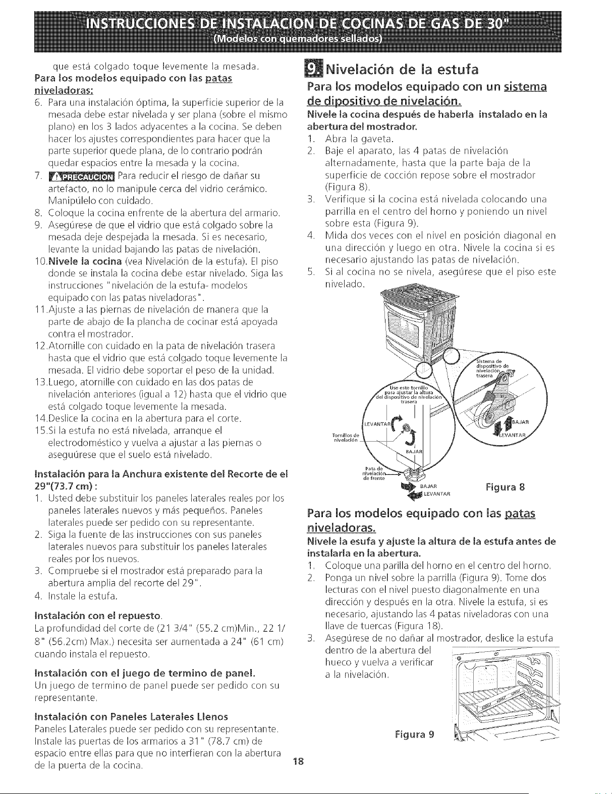
1. Abra la gaveta.
2. Baje el aparato, las 4 patas de nivelaci6n
alternadamente, hasta que la parte baja de la
superficie de coccion repose sobre el mostrador
(Figura 8).
3. Verifique si la cocina esta nivelada colocando una
parrilla en el centro del horno y poniendo un nivel
sobre esta (Figura 9).
4. Mida dos veces (on el nivel en position diagonal en
una dire(cion y luego en otra. Nivele la cocina si es
necesario ajustando las patas de nivelacion.
5. Si al cocina no se nivela, aseg0rese que el piso este
nivelado.
Figura 8
Para los modeios equipado con ias patas
NiveIe ta esufa y ajuste la altura de ta estufa antes de
insta[ar[a en [a abertura.
1. Coloque una parilla del horno en el centro del horno.
2. Ponga un nivel sobre la parrilla (Figura 9). Tome dos
lecturas con el nivel puesto diagonalmente en una
direccion y despues en la otra. Nivele la estufa, si es
necesario, ajustando las 4 patas niveladoras con una
Ilave de tuercas (Figura 18).
3. AsegOresede no dafiar al mostrador, deslice la estufa
dentro de la abertura del
hueco y vuelva a verificar
a la nivelacion.
Figura 9
18
Instalacion de Accesorio
Decorativo Trasero (si se requiere)
1. Desconecte la alirnentaci6n del aparato.
2. Aseg0rese de que el aparato est_ nivelado.
3. Tire la cocina hacia usted.
4. Tome la distancia entre el piso y la superficie debajo
del marco de la porte superior de la cocina.
5. Marque la distancia sobre la pared donde instalara el
accesorio decorativo.
6. Dibuje una linea.
7. Coloque la porte superior del accesorio decorativo
debajo de esa linea.
8. Utilizando los tornillos provistos con este juego, fije el
accesorio decorativo a la pared.
9. Deslice el aparato hacia atr_s hasta que quede en la
position deseada y encienda la alimentacion (la porte
inferior de la porte superior de la cocina debe estar
ubicada sobre el accesorio decorativo).
la cocina
Figura 10
Comprobad6n del fundonamiento
Consulte el Manual de! Usuario inclu[do con la estufa
para instrucciones de operaci6n y instrucciones para el
cuidado y limpieza de su estufa.
No toque Ioselementoso quemadores. Pueden estar
bastante calientes para causar quemaduras.
Quite todo el embalaje de la unidad antes de
comprobarla.
11.1 Instala los Bases y los topos de los
Quemadores
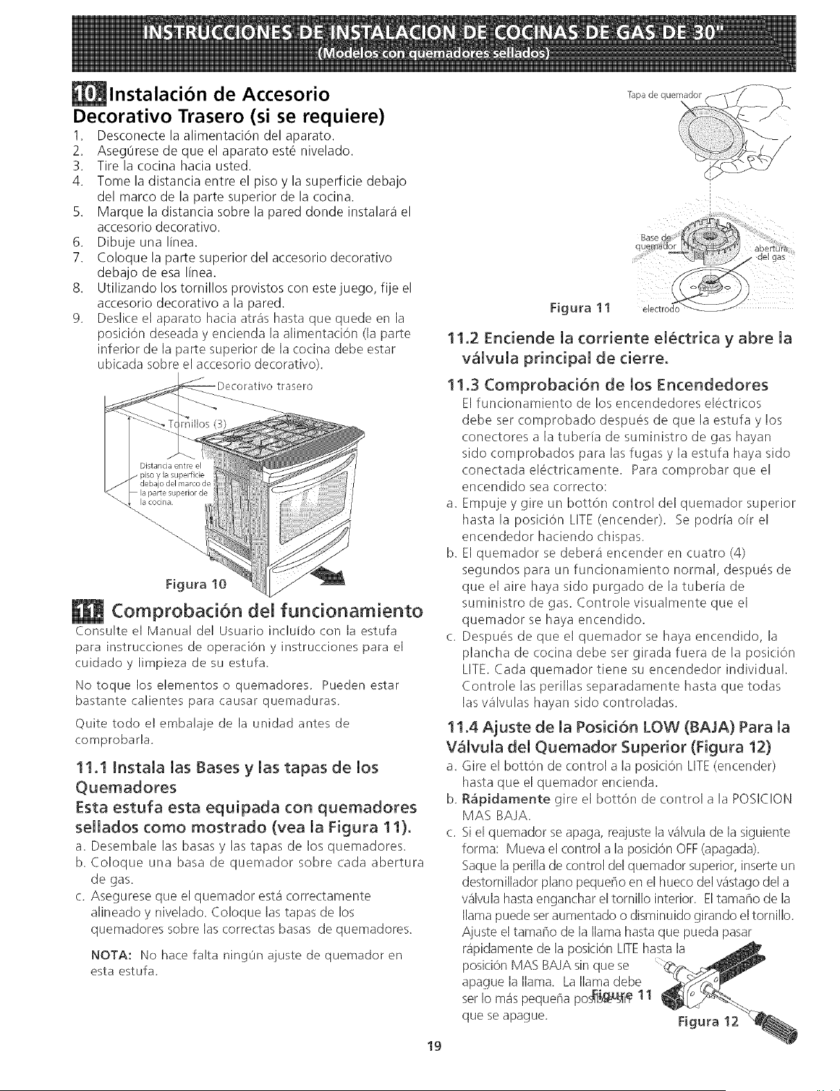
Esta estufa esta equipada con quemadores
sellados como mostrado (vea la Figura 11).
a. Desembale las basas y las tapas de los quemadores.
b. Coloque una basa de quemador sobre cada abertura
de gas.
c. Asegurese que el quemador est& correctamente
alineado y nivelado. Coloque las tapas de los
quemadores sobre las correctas basas de quemadores.
NOTA: Nohacefalta ning0najustedequemadoren
esta estufa.
19
Tapa de quernado_
1
Figura 11
11.2 Enciende la corriente el@ctrica y abre la
v_lvula principal de cierre.
11.3 Comprobaci6n de los Encendedores
Elfun(ionamiento de los encendedores electricos
debe set (omprobado despues de que la estufa y los
conectores a la tuberia de suministro de gas hayan
sido comprobados para las fugas y la estufa haya sido
conectadaelectricamente. Paracomprobarqueel
encendido sea correcto:
a. Empuje y gire un bott6n control del quemador superior
hastala posi(i6n LITE(encender). Sepodriaoirel
encendedor haciendo chispas.
b. El quemador se debera encender en cuatro (4)
segundos para un funcionamiento normal, despues de
que el aire haya sido purgado de la tuberia de
suministro de gas. Controle visualmente que el
quemador se haya encendido.
c. Despu6s de que el quemador se haya encendido, la
plancha de (ocina debe set girada fuera de la posici6n
LITE. Cada quemador tiene su encendedor individual.
Controle los perillas separadamente hasta que todas
los valvulas hayan sido controladas.
11.4 Ajuste de la Posici6n LOW (BAJA) Para la
V_lvula del Quemador Superior (Figura 12)
a. Gire el bott6n de control a la posici6n LITE(encender)
hasta que el quemador encienda.
b. R_pidamente gire el bott6n de control a la POSIC!ON
MAS BAJA.
c. Si el quemador se apaga, reajuste la %lvula de la siguiente
forma: Mueva el (ontrol a la posici6n OFF(apagada).
Saque la perilla de control del quemador superior, inserteun
destomillador piano pequdio en el hueco del v_stago del a
valvula hasta enganchar el tornillo interior. El tama¢io de la
llama puede seraumentado o disminuido girando eltornillo.
Ajuste el tama¢io de la llama hasta que pueda pasar
r@idamente de la posici6n LITEhasta la
posici6n MAS BAJA sin que se
apague la llama. La llama debe
set Io mas pequdia pos_!_'_ 11
que se apague. Figura 12
11.50peracion de Quemadores dei Homo y
Ajustes de Homo
11.5.! Quemadore de ignicOn electrica
La operaci6n de los encendores elOctricosdebe de ser
revisada despOesde que la cocina y los conectores de la linea
de suministro haya sido cuidadosamente revisadapara
descartar fugas y que la cocina haya sido conectada a la
coriente elOctrica.
Elquemador del homo esta equipado con un sistema de
control electrico as[como un encendedor de quemador de
homo electrico. Si su modelo esta equipado con un
quemador de asado central superior, tambien contara con un
encendedor de quemador electrico. Estossistemasde control
no requieren aiustes. Cuando el homo esta configurado para
operar, la coriente fluir_ hacia el encendedor y tendra un
resplandor de manera similar a una bombilla de luz. Cuando
el encendedor a alcanzado una temperatura suficiente para
encender el gas, la valvula del homo (ontrolada
electricamente se abrira y el fuego aparecera en el quemador
del horno, hay un lapso de tiempo de 30 a 60 segundos
depues de que el termostato se endende y antes de que la
llama aparezca en el quemador del horno. Cuando el homo
alcanza la configurad6n del dial, el encendedor
resplandeciente se apagara, la llama del quemador
desaparecera por 20 a 30 segundos despues de que el
encendedor se apage. Para mantener qualquier temperatura
de homo dada, este ciclo continuara tanto como el dial (o
visualizador) este configurado para operar.
Despues de retirar todos los materiales del empaque y la
literatura del homo:
a) Fijeel homo en HORNEAR(BAKE)a 300°F. Vea la guia de
Usoy Cuidado para conocer las instrucciones de
funcionamiento.
b) En60 segundos el quemador del homo se encendera.
Reviseque exista un fuego adecuado, y permita que el
quemador cumpla su ciclo una vez. Gire los controladores
hacia off (APAGADO).
c) Sisu modelo esta equipado con un asador central superior,
file el homo en ASAR.Vea la Guia de Uso y Cuidado para
conocer las instrucciones de funcionamento.
d) En60 segundos el quemador de asar debe de encenderse.
Revisesi exista una llama adecuada. Gire los controles
hacia off (APAGADO).
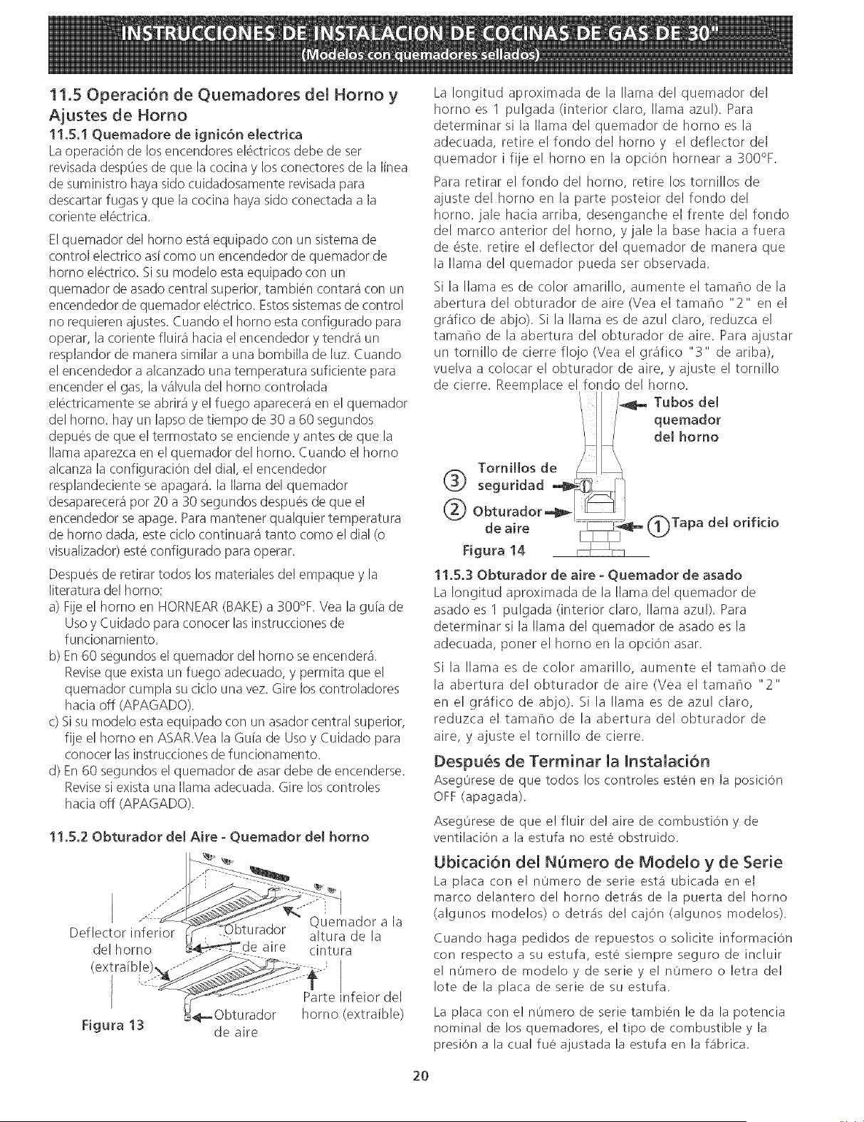
11.5.20bturador del Aire - Quemador del homo
///"
Deflector inferior aturador
del homo aire
_-Obturador
Figura 13 de aire
Quemador a la
altura de la
cintura
Parte nfeior del
horno (extraible)
La Iongitud aproximada de la llama del quemador del
homo es 1 pulgada (interior claro, llama azul). Para
determinar si la llama del quemador de homo es la
adecuada, retire elfondodelhomoy el deflectordel
quemador i file el homo en la opcic_n hornear a 300°F.
Para retirar el fondo del homo, retire los tornillos de
ajuste del homo en la parte posteior del fondo del
homo. jale hacia arriba, desenganche el frente del fondo
del marco anterior del homo, y jale la base hacia a fuera
de 6ste. retire el deflector del quemador de manera que
la llama del quemador pueda set observada.
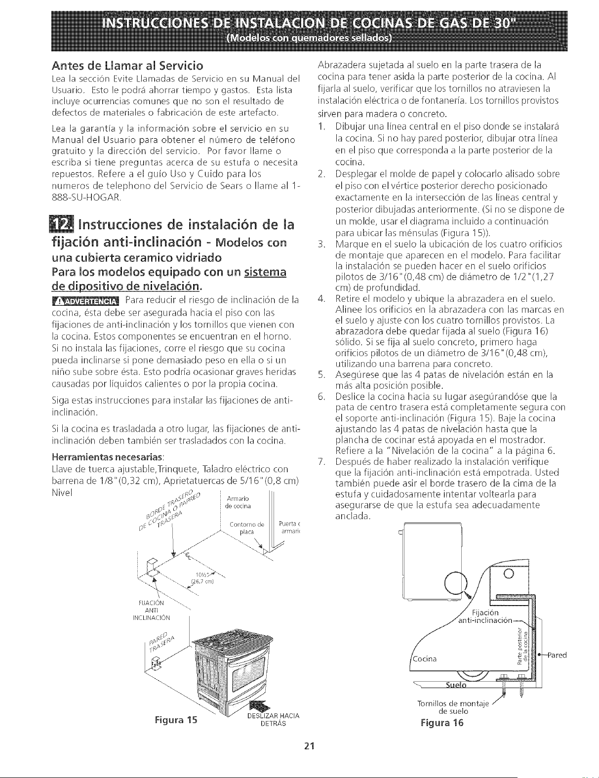
Si la llama es de color amarillo, aumente el tamar-lo de la
abertura del obturador de aire (Vea el tamar-lo "2" en el
grafico de abio). Si la llama es de azul claro, reduzca el
tamar-lo de la abertura del obturador de aire. Para ajustar
un tornillo de cierre flojo (Vea el gr_fico "3" de ariba),
vuelva a colocar el obturador de aire, y aiuste el tornillo
de cierre. Reemplace el fondo del homo.
/_ Tubos del
quemador
(3_ T°rnill°sde !_ \, delhorno
seguridad _i_ / L
de aire _=_ _Tapa del orificio
Figura 14
11.5,30bturador de aire - Quemador de asado
La Iongitud aproximada de la llama del quemador de
asado es I pulgada (interior claro, llama azul). Para
determinar si la llama del quemador de asado es la
adecuada, poner el homo en la opci6n asar.
Si la llama es de color amarillo, aumente el tamaho de
la abertura del obturador de aire (Vea el tamarlo "2"
en el gr_fico de abjo). Si la llama es de azul claro,
reduzca el tamaho de la abertura del obturador de
aire, y ajuste el tornillo de cierre.
Despu_s de Terminar la Instalacion
AsegOresede que todos los controles esten en la posiciOn
OFF(apagada),
AsegOrese de que e! fluir de! aire de combustion de
ventilaciOn a la estufa no este obstruido,
Ubicacion del NOmero de Modelo y de Serie
La placa con el n0mero de serie est,1 ubicada en el
marco delantero de! homo detra's de la puerta del homo
(algunos modelos) o detra_sdel cajOn (algunos modelos).
Cuando haga pedidos de repuestos o solicite informaci6n
con respecto a su estufa, este siempre seguro de incluir
el nOmero de modelo y de serie y el nOmero o letra del
Iote de la plata de serie de su estufa.
La plata con e! nOmero de serie tambien le da la potencia
nominal de los quemadores, e! tipo de combustible y la
presi6n a la cual fue ajustada la estufa en la f4brica.
2O
Antes de Llamar a[ Servkio
Lea la secci6n Evite Llamadas de Servicio en su Manual del
Usuario, Esto le podr_ ahorrar tiempo y gastos, Esta lista
incluye ocurrencias comunes que no son e! resultado de
defectos de materiales o fabricaci6n de este artefacto,
Lea la garantfa y la informaciOn sobre e! servicio en su
Manual de! Usuario para obtener el n0mero de telefono
gratuitoyla direcci6n delservicio, Porfavorllameo
escriba si tiene preguntas acerca de su estufa o necesita
repuestos, Refere a el guio Uso y Cuido para los
numeros de telephono del Servicio de Sears o Ilame al 1-
888%U-HOGAR.
lnstrucdones de instaiad6n de la
fijad6n antHndinad6n - Modelos con
una cubierta ceramko vidriado
Para los modelos equipado con un sistema
_de__pipositivo de nivelad6n.
Para reducir el riesgo de inclinaci6n de la
cocina, esta debe ser asegurada hacia el piso con las
fijaciones de antHnclinaci6n y los tornillos que vienen con
la cocina. Estos componentes se encuentran en el horno.
Si no instala las fijaciones, corre el riesgo que su cocina
pueda inclinarse si pone demasiado peso en ella o si un
nffio sube sobre esta. Esto podr[a ocasionar graves heridas
causadas pot I[quidos calientes o pot la propia cocina.
Siga estas instrucciones para instalar las fijaciones de anti-
inclinaci6n.
Si la cocina es trasladada a otro lugar, las fijaciones de anti-
inclinacion deben tambien set trasladados con la cocina.
Herramientas necesarias:
Llave de tuerca ajustable,Trinquete, Taladro electrico con
barrena de 1/8"(0,32 cm), Aprietatuercas de 5/16"(0,8 cm)
Nivel
Abrazadera sujetada al suelo en la parte trasera de la
cocina para tener asida la parte posterior de la cocina. AI
fijarla al suelo, verificar que los tornillos no atraviesen la
instalacion electrica o de fontaner[a. Lostornillos provistos
sirven para madera o concreto.
1. Dibujar una linea central en el piso donde se instalara
la cocina. Si no hay pared posterior, dibujar otra linea
en el piso que corresponda a la parte posterior de la
cocina.
2. Desplegar el molde de papel y colocarlo alisado sobre
el piso con el v6rtice posterior derecho posicionado
exactamente en la intersecci6n de las Ilneas central y
posterior dibujadas anteriormente. (Si no se dispone de
un molde, usar el diagrama incluido a continuation
para ubicar las m6nsulas (Figura 15)).
3. Marque en el suelo la ubicaci6n de los cuatro orificios
de montaje que aparecen en el modelo. Rata facilitar
la instalaci6n se pueden hacer en el suelo orificios
pilotos de 3/16"(0,48 cm) de diametro de 1/2"(1,27
cm) de profundidad.
4. Retire el modelo y ubique la abrazadera en el suelo.
Alinee los orificios en la abrazadera con las marcas en
el suelo y ajuste con los cuatro tornillos provistos. La
abrazadora debe quedar fijada al suelo (Figura 16)
s61ido. Si se fija al suelo concreto, primero haga
orificios pilotos de un di_metro de 3/I 6 "(0,48 cm),
utilizando una barrena para concreto.
5. Aseg@reseque las 4 patas de nivelacion est_n en la
m_s alta posici6n posible.
6. Deslice la cocina hacia su lugar aseg@rand6seque la
pata de centro trasera est_ completamente segura con
el soporte antiqnclinaci6n (Figura 15). Baje la cocina
ajustando las 4 paras de nivelacion hasta que la
plancha de cocinar est& apoyada en el mostrador.
Refiere a la "Nivelaci6n de la cocina" a la pagina 6.
7. Despu6s de haber realizado la instalaci6n verifique
que la fijacion antiqnclinacion est_ empotrada. Usted
tambien puede air el borde trasero de la cima de la
estufa y cuidadosamente intentar voltearla para
asegurarse de que la estufa sea adecuadamente
anclada.
Figura 15
DESLIZAR HACIA
DETRAS
Tornillos de montaje
de sueto
Figura 16
21
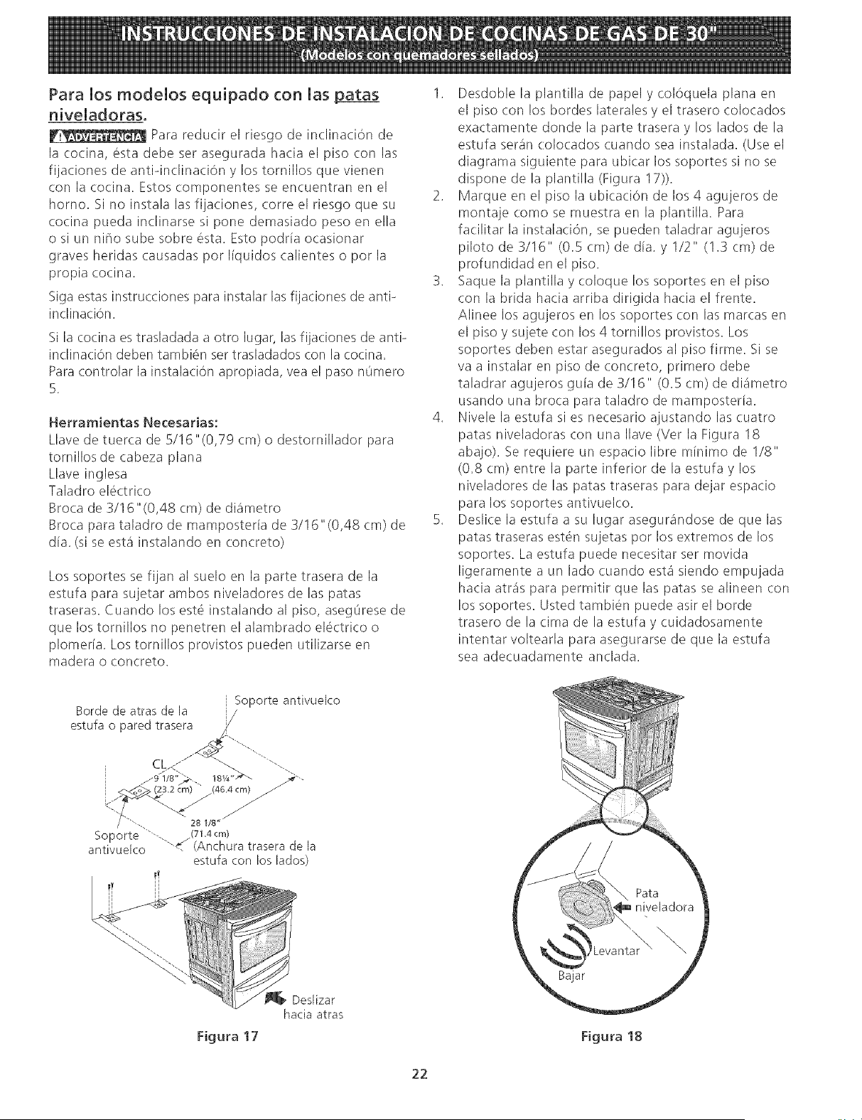
Para los modelos equipado con [as patas
__ Para reducir el riesgo de inclinacion de
la cocina, esta debe ser asegurada hacia el piso con las
fijaciones de antiqnclinaci()n y los tornillos que vienen
con la cocina. Estos componentes se encuentran en el
homo. Si no instala las fijaciones, torte el riesgo que su
cocina pueda inclinarse si pone demasiado peso en ella
o si un nffio sube sobre esta. Esto podrla ocasionar
graves heridas causadas por liquidos calientes o por la
propia cocina.
Siga estas instrucciones para instalar las fijaciones de anti-
inclinaciOn.
Si la cocina es trasladada a otro lugar, las fiiaciones de anti-
inclinaci6n deben tambi6n set trasladados con la cocina.
Para controlar la instalaci6n apropiada, yea el paso nOmero
5.
Herramientas Necesarias:
Llave de tuerca de 5/!6"(0,79 cm) o destornillador para
tornillos de cabeza plana
Llave inglesa
Taladro electrico
Broca de 3/16"(0,48 cm) de diametro
Broca para taladro de mamposteria de 3/16"(0,48 cm) de
dla. (si se esta instalando en concreto)
Los soportes se fijan al suelo en la parte trasera de la
estufa para sujetar ambos niveladores de las patas
traseras. Cuando los est6 instalando al piso, asegL]rese de
que los tornillos no penetren el alambrado electrico o
plomeria. Los tornillos provistos pueden utilizarse en
madera o concreto.
1. Desdoble la plantilla de papel y col6quela plana en
el piso (:on los bordes laterales y el trasero colocados
exactamente donde la parte trasera y los lados de la
estufa seran colocados cuando sea instalada. (Use el
diagrama siguiente para ubicar los soportes si no se
dispone de la plantilla (Figura 17)).
2. Marque en el piso la ubicaci6n de los 4 agujeros de
montaje como se muestra en la plantilla. Para
facilitar la instalaci6n, se pueden taladrar agujeros
piloto de 3/16" (0.5 (m) de dia. y 1/2" (1.3 cm) de
profundidad en el piso.
3. Saque la plantilla y coloque los soportes en el piso
con la brida hacia arriba dirigida hacia el frente.
Alinee los agujeros en los soportes (on las marcas en
el piso y sujete (:on los 4 tornillos provistos. Los
soportes deben estar asegurados al piso firme. Si se
va a instalar en piso de concreto, primero debe
taladrar agujeros gula de 3/16" (0.5 cm) de diametro
usando una broca para taladro de mamposteria.
4. Nivele la estufa si es necesario ajustando las (uatro
patas niveladoras (:on una Ilave (Vet la Figura 18
abajo). Se requiere un espa(io libre minimo de I/8"
(0.8 cm) entre la parte inferior de la estufa y los
niveladores de las patas traseras para dejar espacio
para los soportes antivuelco.
5. Desli(e la estufa a su lugar asegur_ndose de que las
patas traseras est6n sujetas pot los extremos de los
soportes. La estufa puede necesitar set movida
ligeramente a un lado cuando esta siendo empujada
hacia atr_s para permitir que las patas se alineen (.on
los soportes. Usted tambien puede asir el horde
trasero de la cima de la estufa y cuidadosamente
intentar voltearla para asegurarse de que la estufa
sea adecuadamente anclada.
Soporte antivuelco
Borde de atras de [a
estufa o pared trasera
C ...................
/9 1/8' 18V_ "-_ _'-
28 1/8"
Soporte ""--. /(71_4cm)
antivuelco '--.. (Anchura traserade [a
estufa con los [ados)
eslizar
hacia atras
Figura 17 Figura 18
22
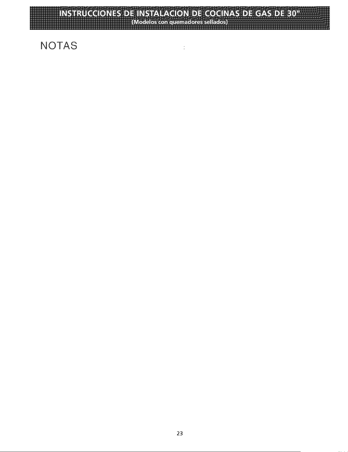
NOTAS
23

NOTAS
24
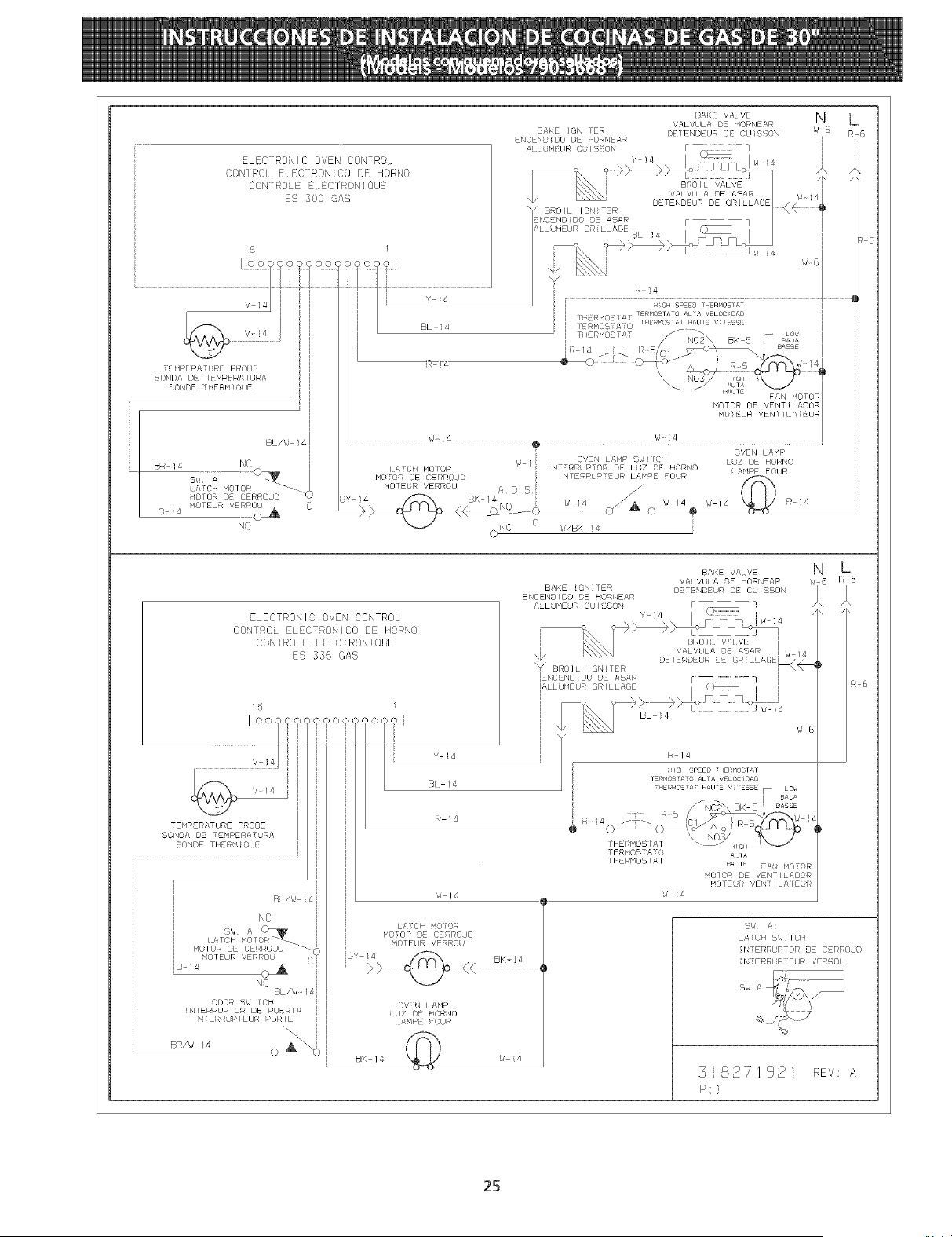
E_ECIAONIE 0VEN EONFROL
CONIA01 EiECFRONiC0 [)E HORN0
CONIR@E FLFC]RONiOUF
rS 300 8£S
IB /
BAKE ]GNIFER
ENCENBIDO DE HORNEAR
_IIUMt[/JR CUISgBN
Y !4
hLLOHEUR GRILLAGE
BL 14
BAK VALVI
VALVULA BE HORNEAR
DEFEND UR DI BUISX)N
....... I
T HPEAA BRE PkBBE
BNI)A DE ]_HPERA URA
SONDE Z!iER!'_ ] ©LJE
BA I 4 NO
A (}kl MOTOR "_'-._
FLOOR B QERROJD
_4OTEU_ VERROU
04 0 A
NO
R T_
N L
'd 6
A
W 14 W 4
O .............
i OVEN LAHP
_ OVEN LAHP Sbi]ICH LUZ DE HBRNO
I NTERr_UPTOR DE LUZ DE !I©RNO _ A_P F ¸ R
I NTERRUPTEUR LAMPE BUR _ E BU
C '_v/BK 4
_6
ELECTRON]C OVEN CONTROL
CONTROL ELECTRONIC0 DE IqORN0
CONTROLE ELEC_RON]OUE
ES 335 GAS
Ioo _coooc
.... V 14
TENPERA TU_E P_OBE
50NBA DE TEHPEF/AT_RA
SONDE TItERH [ ©UE
NC
DBOR S_IT(}H
INIERAUPlOR DE PUEATA
[NTE_RUPTEUR PORTE
\
\\
BR/_ 14
BK 14
)oc 0 J
Y }d
BI 14
Iq 4
_ /4
Lff]GH HOiOR
HOTOR ©E CE£ROJO
MOTEUR VERROU
BVIN I)HP
{UZ [3 HORNB
i /\HP fBUR
©
BAKE IGNITER
ENCENDIDO DE HO£NEAR
ALLOMEUR EUlSSON
J 4
IALLUMELJR GRILLAGE
I
\
BAKE VA V_'
'!ALVULA BE HORNEAR
DETENDEUF/ DE CU[SBO
F
v , 4 (_
/d 14
BRB)L VALVE i
w 14
BL 4
J 6
R 14
HIGII SP_ED ;IIERmDSr£T
TEF_N©S[AFO ALr£ VELOCJDAD
_EA_OSi4_ H_U_E V_TdSSE F LO_
FERHOSIAFO
TIIER_OSTAT
_UTE bAN _OTOA
_OTOR DE VENTILADOR
HOIEUR VENf]LAIEUR
N L
6
Sla /s
LATCI I BW] TCIq
NTERRUPTOR DE CERROJO
i N[ERRUP I EUR VERROU
3 827192 REV: ,_,
P:i
2B
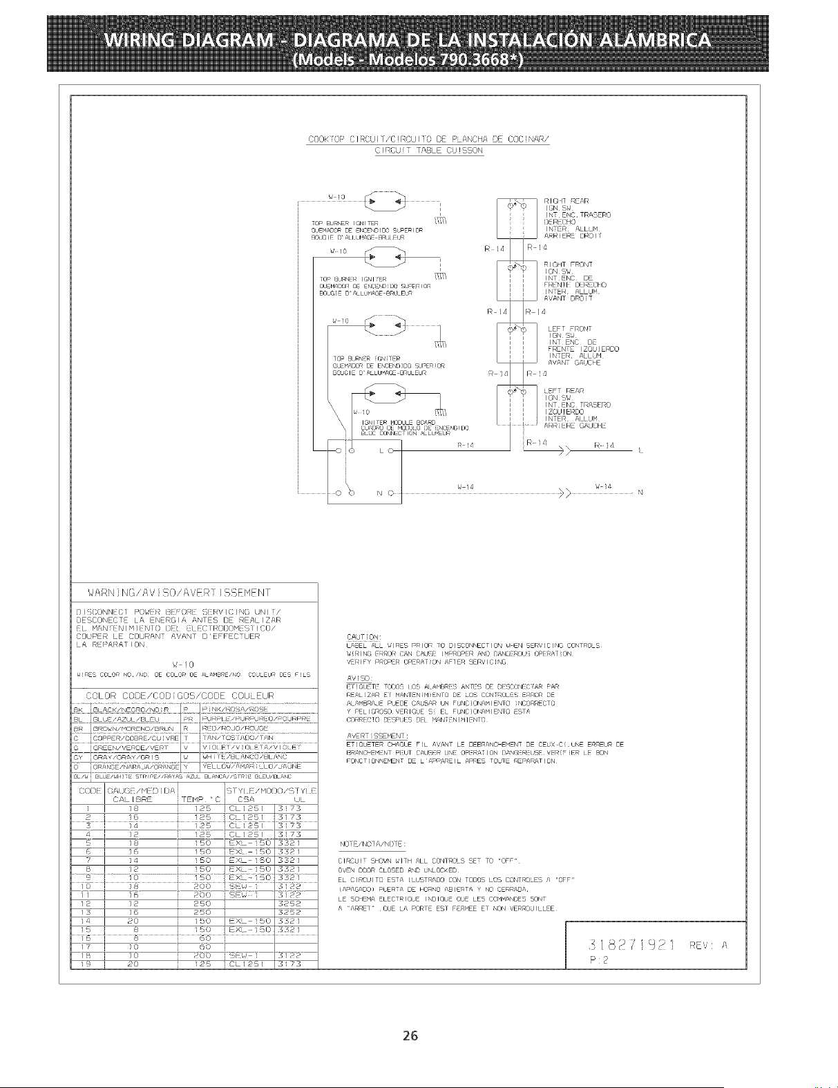
COOK OP i_i]f_CUl [/C}RCUl !0 DE PLANCHA DF CO{I}NAf]/
C I RCU i T TABLE CU }SSON
WARNING/AId SO/AVER ]SSEMENF
) ] 5(ONNI ( / P(JWl _ 17{{ OStl S!RV I C I NO UN I /
DESCONECTE LA ENERGIA ANTES DE REALIZAR
COUPER LE COURANT AVANT D' EFFECTUER
LA I:_EI_ARA/ I ON
W !0
_RES COLOR NO/NO OE COLOR OE ALAHBRE/NO CO_JLEUR OE5 FILS
COLOR CODb/COD', COS/CODE COU EUR
i /ii
coEf F_F'C£_SE/CU £ZRE 1 /}N_i I CS J}CII/TI/9 ..........
GREEN/VEr_DE/\/EF@T V V 0i E /V 0 A/VI( E
Gy GF_AY/GF_AY / GF_I S _J _Jn [ E/_L/_,hJ 8/_LMN
i_7 FYt E/MODO/STY! E
FENP _ C I CSA UL
/ I 18 i /25 ICL125/ 3!73
3 ] 14 125 iOLi25[ 3173
_--I ]2 i !25 10L125/ 373
I 18 i !50 I EXL 150 3_21
_ I 16 i 150 i_xl i50 _321
7 I 14 !_0 I£XL 150 1321
I _ i !5o /_xi_o ss_
11 I ]6 i 200 I SEWl 3122
12 I 12 i 260 I S252
_s I _6 i 250 i 3252
_4 I 20 /50 IdXL 150 3321
/9 I 20 i 125 10L125/ 31F3
LABEL ALL 'UIRES PRIOR TO DISCONNECTIO% W_N SERVICING CONTROLS
WIRING ERROR CAN CAUSE I_PROPER AND {)ANGEROUS OPERAriON
dEl_l_Y P_OPER OPERArfo_ AFIE_ SERVICING
AVIS0:
(ET !OUi!iTE ! O[)Of_ t O!!_ At AMBF/_]!3 AN I E8 DE D({SCON[!8 ! AR PAR
F_EAL_ZaR El HANrENiM_ENrQ DE LOS CONFf@OLES E_F©R DE
ALAMBRAJE PUEDE CAUSAR UN FUNC]ONAMIENTO )NCORRECTO
Y PEL)GROSOVERIQUE S{ EL FUNC]ONAMIENTO ESTg
CORR(!!XHO DESPUES DEt MAN[ENIMIENrO
AdERT{SSEHENT:
ET!QUETER CHAQUE F!L AVANT LE DEBRANCHE_ENT DE CEUX C{U_ ERREUR DE
(!_ANCHEHENW PEUT CALJSEF_UNE 0PEi_A$10N DAM;EF_i_USEV(_R{Fi(![R i(!! [_()N
FO_CT}ONNE_ENT DE LDPPA_EIL APRE5 TORTE £_PAR@TION
N0 i E iN()] A/N0 i E :
C I RCU I T SHO_SN _'] TH At • CONTROLS SET TO "OFF"
OVEN DOOR CLOSED AND b'NLOCKED
EL CIRCL, ITO ESTA ILUST_ADO CON TODOS LOS CONT_OLES A "OFF"
(APAGADO_ PUERTA DE HORNO ABIE_T/t Y NO CERRADA
LE SCIIEHA ELECTRIQUE INDIOUE OUE LES CGVMANDES SONT
A >ARRET '¸ OUE LA PORTE EST FE_<dEE ET NON VEFT_OUILLEE
P:2
26

0-14
IdOTOR DOOR LATCH
MOTOR DE LOQUETA
DE PUERTA
MOTEUR PORTE VERROU
DOOR SWITCH
INTERRUPTOR DE PUERTA
INTERRUPTEUR PORTE
BR/W. 14c__ BL/W 14
OVEN CIRCUITi/CIRCUITO DE HORNO//CIRCUIT FOUR
ELECTRONIC OVEN CONTROL
CONTROL DE HORNO ELECIRONICO
CONTROLE ELECTRONIQUE FOUR
ES 350
BAKE IGNITER
ENCENDIDO DE HORNEAR
DLB
BAKE VALVE
VALVULA DE HORNEAR
VALVE DE OUIGSON
N L
d-5 R-6
/ \ /\
VALVULA DE ASAR W-14
VALVE DE GRILLAGE <_
R 6
BROIL IGNITER
_:ENCENDIDO DE ASAS [ _ ]
ALLUMEUR GRILLAGE BL 14 I IW.14
k
W-6
CONVECTION MOTOR
/ MOTOR DE CONVECCION
MOTEUR CONVECTION
BR 14 BR 14
R 14
R 14
LOW
BAJA
lENT
THERMOSTAT
FAN MOTOR
MOTOR DE VENTILADOR
MOTEUR VENTILATEUR
¢J-14
HIGH SPEED THERMOSTAT
TERMOSTATO ALTA VELOCIDAD HIGH
THERMOSTAT HAUTE VITESSE ALTA
HAUTE W-14
W-14
LATCH MOTOR
MOTOR CERROJO
MOTEUR VERROU
GY 14/_/ _( BK 14
OVEN LAMP
LUZ DE HORNO
LUf_IERE FOUR
BK-14 W 14
COOKTOP CIRCUIT / CIRCUITO DE PLANCHA DE COCINAR / CIRCUIT TABLE CUISSON
N
WSL2 R-14 R 14
R-5 I I
R 14
RIGHT REAR IGNITER SWITCH. W 23 _@_
INTERRUPTOR ENCENDIDO
TRASERO DERECHO
INTERROPTEUR ALLUMEUR IGNITER MODULE BOARD
ARRIERE DROIT CUARDO DE MODULO DE ENCENDIDO TOP BURNER
BLOC CONNECTION ALLUMEOR QUEMADOR DE ENCENDIDO SUPERIOR
RIGHT FRONT IGNITER SWITCH. BOUGIE D ALLUMAGE BRULEUR
I.TEO UPTORENOENOIO00 0 23g
FRENTEOEREO"O _ i
INTERRUPTEUR ALLOMEOR O _/" _F i
AVANT DROIT TOP BURNER
QUEMADOR DE ENCENDIDO SUPERIOR
BOOGIE D'ALLUMAGE BRULEOR
LEFT FRONT IGNITER SWITCH.
INTERRUPTORENCENDIDO W23_@_FRENTE IZQU[ERDO
INTERRUPTEOR ALLUklEUR W 14 R 14
AVANT GAUCHE TOP BURNER
QUEMADOR DE ENCENDIDO SUPERIOR
BOUGI5 DALLUNAGE BRULEUR
LEFT REAR IGNITER SWITCH,
INTERRUPTOR ENCENDIDO W23 _
TRASERO IZQUI ERDO _ i
INTERRUPTEUR ALLUMEUR i_ "
ARRIERE GAUCHE
TOP BURNER
OUE&_AOOR DE ENCENDIDO SUPERIOR
BOUGIE DALLUMAGE BRULEUR
COLORS/CODIGOS/CODE COULEUR
BK,-BLACKJNEGRO/NOIR
G. GREEN/VERDE/VERT
W. WHITE/BLANOO/BLANC
R, RED/ROJO/ROUGE
O,-ORANGE/NARANJA/ORANGE
Y. YELLOW/AMARILLO/JAUNE
BR. BROWN/MORENO/BRUN
BL, BLUE/AZUL/£LEU
SW.A
LATCH raOTOR
MOTOR DE CERROJO
MOTEUR VERROU
I I
CODE GAUGE TEMP,"C CSA UL
CODIGO MEDIDA
CODE CALIBRE
1 18 125 CL1251 3173
2 16 125 CL1251 3173
3 14 125 CL1251 3173
4 12 125 CL1251 3173
5 18 150 EXL 150 3321
6 16 150 EXL-150 3321
7 14 150 EXL-150 3321
8 12 150 EXL-150 3321
9 10 150 EXL 150 3321
10 18 200 SEW-1 3122
11 16 200 SEW-1 3122
12 12 250 3252
13 16 250 3252
14 20 150 EXL-150 3321
15 8 150 EXL 150 3321
16 8 60
17 10 60
18 10 200 SEW-1 3122
19 20 125 CL1251 3173
20 20 200 SEW I 3122
21 22 125 CL-1251 3173
22 22 150 EXL-150 3321
23 18 200 3573
CAUTION: DISCONNECT CURRENT BEFORE REMOVING REAR COVER.
ATENCION:CORTAR EL CORIENTE ANTES DE REALIZAR EL MANTENIMIENTO GEL ELECTRODOMESTZCO.
ATTENTION:COUPEZ L'ALIMENTATION AVANT D'EFFECTUER LA REPARATION.
318271924 REV:A
27
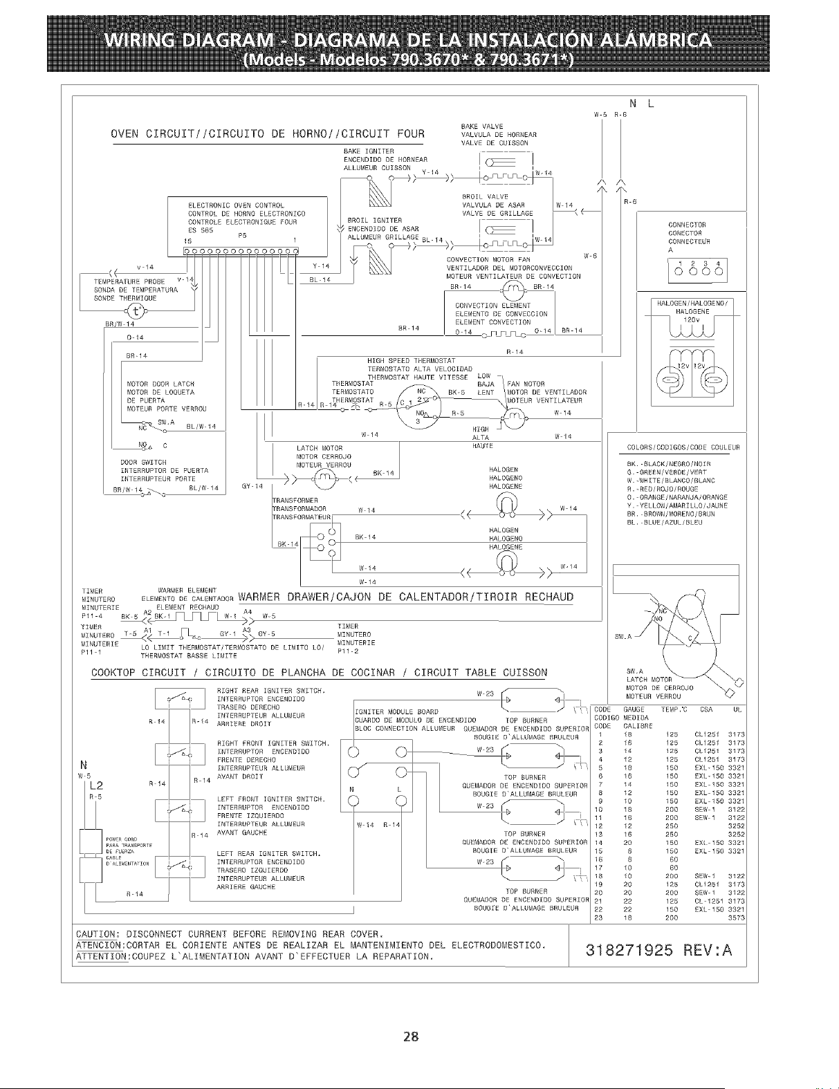
OVEN CIRCUIT//CIRCUITO DE HORNO//CIRCUIT FOUR
SAKE IGNITER
ENCENDIDO DE HORNEAR
SAKE VALVE
VALVULA DE HORNEAR
VALVE DE COISSON
IW14
BROIL VALVE
VALVULA DE ASAR
N L
W5 R 6
/k /x
BR/W 14
0-14
BR-14
MOTOR DOOR LATCH
MOTOR DE LOQUETA
DE PUERTA
MOTEUR PORTE VERROU
BL/W 14
N_ C
DOOR SWITCH
INTERRUPTOR DE PUERTA
INTERRUPTEBR PORTE
BR/W 1_ c SL/W 14
TIMER
IdZNOTERO
SR 14
BR-14 .j_F_]_ BR 14
CONVECTION ELEMENT
ELEMENTO DE CONVECCZON
ELEMENT CONVECTION
0 14 O F_LFL_ 0-14 BR 14
R 14
HIGH SPEED THERMOSTAT
TERMOSTATO ALTA VELOCIDAD
LOWTHERMOSTAT HAUTE VlTESSE
BAJA _ FAN MOTORTHERMOSTAT
TERMOSTATO BK-5 LENT MOTOR DE VENTILAOOR
THERMOSTAT -- MOTEUR VENTILATEUR
R-14 R 14_
W 14 ALTA W 14
LATCH MOTOR HAUTE
MOTOR CERROJO
MOTEUR VERROU
_ _ sK_ RA_OGEN
_ HALOGENO
GY-14 HALOGENE
"R_NS_ORME_ << ? >>
"RANSFORMAOOR W 14 W 14
HALOGEN
BK 14 HALOGENO
HALOSENE
<< ? >> w.4
w 14
WARMER ELEMENT
ELEMENTODECALENTASORWARNER DRAWERiCAJON DE CALENTADOR/TIROIR RECHAUD
W-5
TIMER
A1 AG%VI <_3_ SY 5 MINSTERO
MINO,ERO_ ,I oFL_
MINUTERIE LO LIMIT THERMOSTAT/TERMOSTATO// DE LIMITO LO/ MINUTERIE
Pll 1 Pl1-2
TNERf_OSTAT BASSE LIMITE
COOKTOP CIRCUIT / CIRCUITO DE PLANCHA DE COCINAR / CIRCUIT TABLE CUISSON
R14
N
w 5
L2 R 14
I-I.........
pARA TRA SPORTE
,._| RIGHT REAR IGNITER SWITCH,
INTERRUPTOR ENCENOIDO
TRASERO DERECHO
R-14 INTERRUPTEUR ALLUMEUR
ARRIERE DROIT
RIGHT FRONT IGNITER SWITCH,
,_a_,'RJ11NTERRUPTORENCENDIDO
FRENTE DERECHO
INTERRUPTEUR ALLUMEUR
4 AVANT DROIT
LEFT FRONT IGNITER SWITCH.
_W4 INTERRUPTORENOENDIDo
FRENTE IZQUIERDO
ZNTERRUPTESR ALLU_IEUR
AVANT GAUCHE
LEFT REAR IGNITER SWITCH,
,.._&K_J INTERRUPTOR ENCENDIDO
TRASERO IZQUIERDO
INTERRUPTEUR ALLUMSUR
ARRIERE GAUCHE
IGNITER MODULE BOARD
CUARDO DE MODULO DE ENCENDIDO TOP BURNER
BLOC CONNECTION ALLUNEUR QUEMADOR DE ENCENDIO0 SUPERIOR
BOOGIE D'ALLUMAGE SRULEUR
W 14 R 14
TOP BURNER
QUEMADOR DE ENCENDIDO SUPERIOR
BOUGIE O'ALLUMAGE BRULEUR
W 23 I b 4F I
TOP BURNER
QOEMADOR DE ENCENDZDO SUPERIOR
BOOGIE D'ALLUMAGE SRULEUR
/ \
wsBi 1,
TOP BURNER
QUEMAOOR DE ENSENDESO SUPERIOR
BOUGEE DALLUMAGE BRULEUR
CONNECTOR
CONECTOR
CONNECTEUR
A
d6661
HALOGEN/HALOGENO/
HALOGENE
Z.Y
CAUTION: DISCONNECT CURRENT BEFORE REMOVING REAR COVER.
ATENCZON:CORTAR EL CORIENTE ANTES DE REALZZAR EL MANTENIMZENTO DEL ELECTRODOMESTICO,
ATTENTZON:COUPEZ L'ALINENTATION AVANT D'EFFECTUER LA REPARATION.
COLORS/CODIGOS/CODE COULEUR
BK. SLACK/NEGRO/NOIR
G. GSEEN/VSROE/VERT
W.-WHITE/BLANCO/SLANC
R.-RED/ROJO/ROUGE
O. ORANGE/NARANJA/ORANGE
Y. YELLOW/AMARZLLO/JAUNE
BR, BROWN/MORENO/BRUN
BL, SLUE/AZUL/BLEU
CODE
CODIGO MEOIDA
CODE CALIBRE
1 18 125 CL1251 3173
2 16 125 CL1251 3173
14 125 CL1251 3173
12 125 CL1251 3173
18 150 EXL-150 3321
6 16 150 EXL-150 3321
7 14 150 EXL 150 3321
8 12 150 EXL 150 3321
9 10 150 EXL-150 3321
10 18 200 SEW 1 3122
11 16 200 SEW 1 3122
12 12 250 3252
13 16 250 3252
14 20 150 EXIt150 3321
15 8 150 EXL_150 3321
16 8 60
17 10 60
18 10 200 SEW_I 3122
19 20 125 0L1251 3173
20 20 200 SEW-1 3122
21 22 125 CL 1251 3173
22 22 150 EXL 150 3321
23 18 200 3573
318271925 REV:A
28