Loading ...
Loading ...
Loading ...
14
DRYER VENTING REQUIREMENTSDRYER VENTING REQUIREMENTS
1. Connect gas supply to dryer. Use a pipe thread compound
approved for the type of gas supplied. If exible metal
tubing is used, be certain there are no kinks.
If necessary for service, open the toe panel. Use a putty
knife to press on the toe panel lock located at the center top
of the toe panel. Pull downward on the toe panel to open.
Toe panel is hinged at the bottom.
2. Open the shut-off valve in the gas supply line and make sure
the dryer has its own gas supply opened.
3. Test all connections by brushing on an approved
noncorrosive leak-detection solution. Bubbles will show a
leak. Correct any leaks found.
Make Gas Connection
GAS SUPPLY CONNECTIONGAS SUPPLY CONNECTION
WARNING
Explosion Hazard
Use a new CSA International approved gas supply line.
Install a shut-off valve.
Securely tighten all gas connections.
If connected to propane, have a qualified person make
sure gas pressure does not exceed 13" (330 mm) water
column.
Examples of a qualified person include:
licensed heating personnel,
authorized gas company personnel, and
authorized service personnel.
Failure to do so can result in death, explosion, or fire.
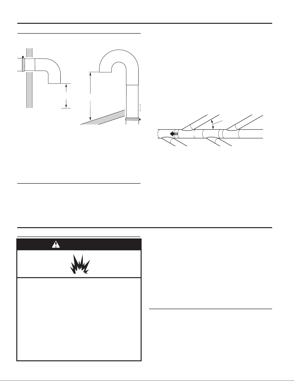
The outside end of main vent should have a sweep elbow
directed downward.
If main vent travels vertically through the roof, rather than
through wall, install a 180° sweep elbow on end of vent at least
2 ft (610 mm) above surface of roof.
The opening in wall or roof shall have a diameter 1⁄2" (13 mm)
larger than vent diameter. Vent should be centered in opening.
Do not install screening over end of vent for best performance.
12" minimum
(305 mm)*
A main vent can be used for venting a group of dryers. The
main vent should be sized to remove 5,663 L/min (200 CFM) of
air per dryer. Large-capacity lint screens of proper design may
be used in main vent if checked and cleaned frequently. The
room where the dryers are located should have make-up air
equal to or greater than CFM of all the dryers in the room.
If an Exhaust Hood Cannot be Used
Multiple Dryer Venting
24" minimum
(610 mm)
* Minimum clearance above any
accumulation of snow, ice, or
debris such as leaves
30˚ maximum
Air flow
Air Flow
Back-draft dampers are available from your distributor and
should be installed in the vent of each dryer to keep exhausted
air from returning into dryers and to keep exhaust in balance
within main vent. Unobstructed return air openings are required.
Although usually each single-load dryer should have an
unobstructed outdoor air opening of 24 in2 (154 cm2) (based
on 1 in2 [6.5 cm2] per 1,000 B.T.U. [252 kcal]), common make-
up air openings are also acceptable. Set up common openings
so the make-up air is distributed equally to all of the dryers.
Keep in mind that the coverage area must be increased by 33%
to account for the use of registers or louvers over the openings.
Also, make-up air openings should not be installed near the
location where exhaust vents exit the building.
Each vent should enter the main vent at an angle pointing in
the direction of the airow. Vents entering from the opposite
side should be staggered to reduce the exhausted air from
interfering with the other vents.
The maximum angle of each vent entering the main vent should
be no more than 30°.
Keep air openings free of dry cleaning uid fumes. Fumes
create acids which, when drawn through the dryer heating
units, can damage dryers and items being dried.
A clean-out cover should be located on the main vent for
periodic cleaning of the vent system.
NOTE: For more dryer venting information, please refer to
Whirlpool document W10100920.
This dryer is equipped for use with natural gas. It is design-
certied by CSA International for Propane (propane and butane)
gases with appropriate conversion. No attempt shall be made
to convert dryer from gas specied on serial/rating plate for use
with a different gas without consulting the serving gas supplier.
Conversion must be done by a qualied service technician.
Gas conversion kit part numbers are listed near gas valve
burner base.
Type of Gas
Loading ...
Loading ...
Loading ...