599116A,03,2003
Uii!!i i:il
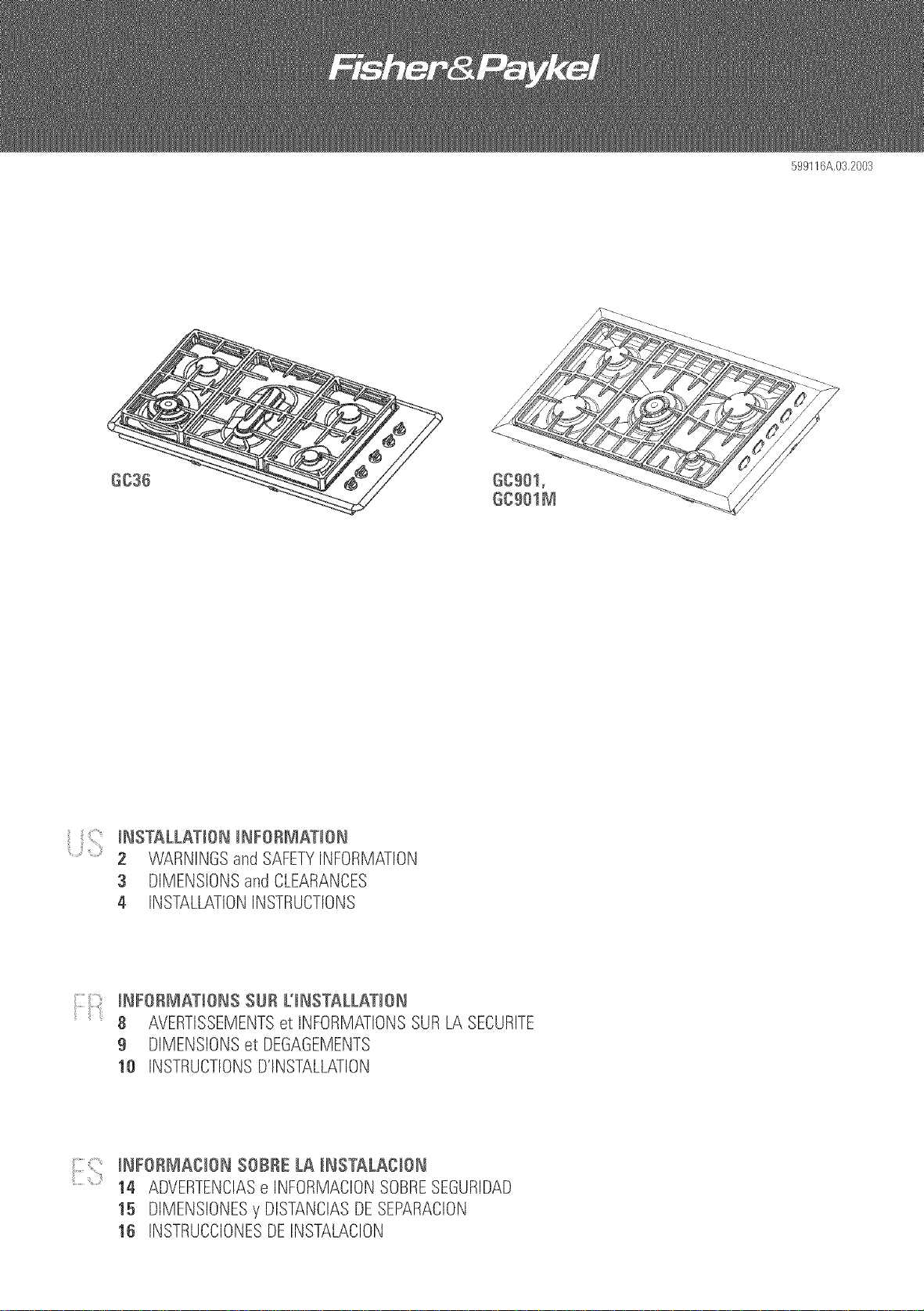
_NSTALLAT_ON_NFORMAT_ON
2 WARNINGSand SAFETYINFORMATION
3 DIMENSIONSand CLEARANCES
8 INSTALLATIONINSTRUCTIONS
_NFORMAT_O_aSSUR L1NSTALLATHON
8 AVERTISSEMENTSet INFORMATIONSSURLASECURITE
9 DIMENSIONSet DEGAGEMENTS
10 INSTRUCTIONSD'INSTALLATION
_NFOR_vlAC_O_aSOBRELA INSTALAC_ON
14 ADVERTENCIASe INFORMACIONSOBRESEGURIDAD
15 DIMENSIONESy DISTANCIASDESEPARACION
16 INSTRUCCIONESDEINSTALACION
WARNINGSAND SAFETYINFORMATION
_ Thisappliance shallbe installedin accordancewith
the installation requirementsof the localgas
authority orthe appropriate installationcode or in the
absence of localcodes with the latest NationalFue!
GasCodeANSIZ2231 orCAN B149.1,2(Canada}
Localbuildingandelectricalcodesmust beadheredto
_J When this applianceis installed it shallnot be used
as a spaceheater
_ No combustiblematerial or productsshouldbe
placed onthis applianceat anytime
_ Donot sprayaerosolsin the vicinity of this appliance
while it is in operation
_ Not to beinstalled ina bathroomor
bedroom/sleepingquarters
_ Flexibleapplianceconnectors shallmeet the
requirementsof ANSI Z2124 and State Boards
Theyshallnot exceed36 inchesin length
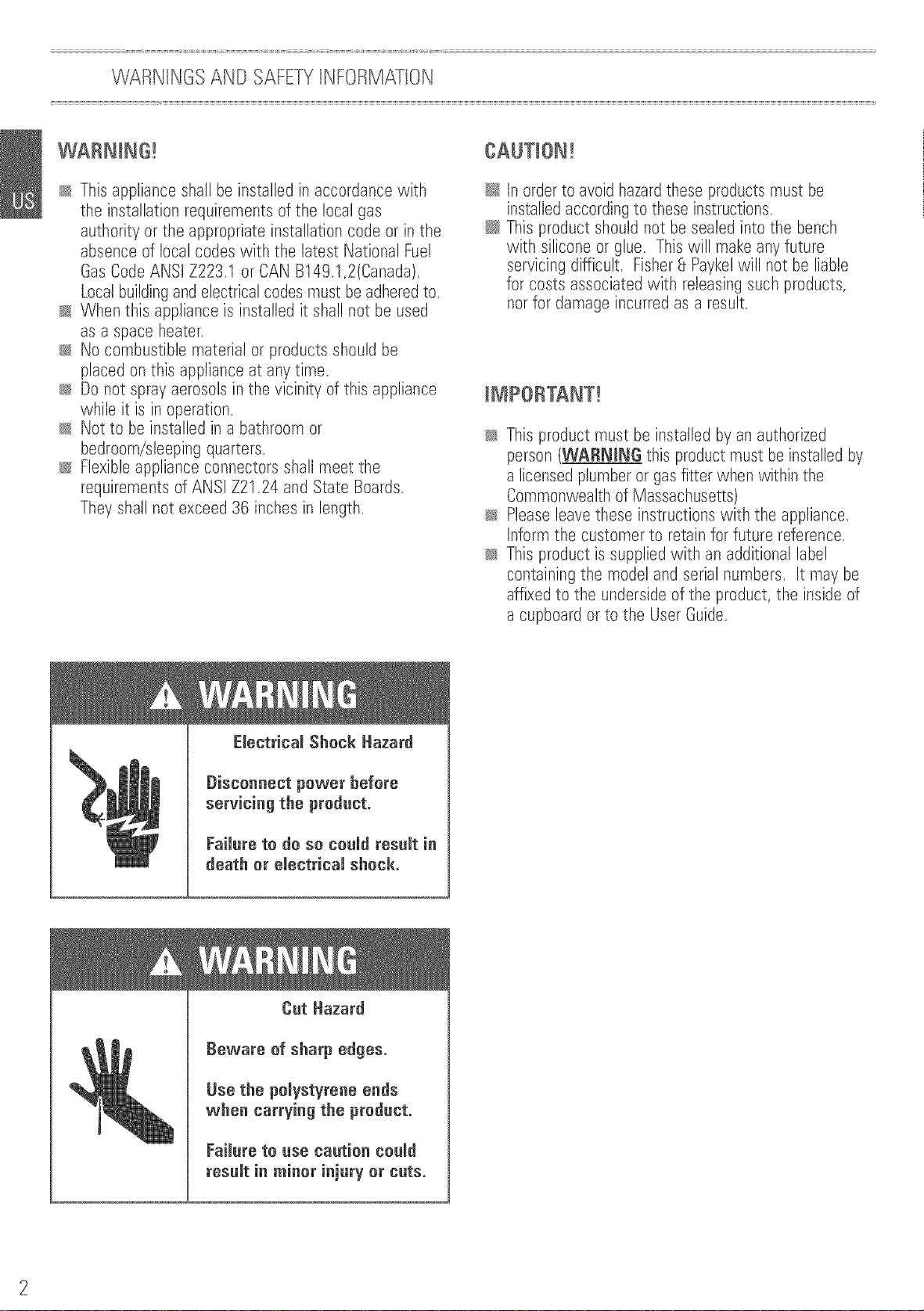
F_eet_iea_ Shec_ _aza_d
CA_T_O_!
@ Inorderto avoidhazardthese productsmust be
installedaccordingto theseinstructions
@ This product shouldnot besealedinto the bench
with silicone or glue Thiswill makeanyfuture
servicingdifficult Fisher8 Payke!will not be liable
for costs associatedwith releasingsuchproducts,
norfor damageincurredas a result
_ Thisproduct must be installed by anauthorized
person(W_ll@; this productmust beinstalledby
a licensedplumberorgasfitter when within the
Commonwealthof Massachusetts}
_ Pleaseleavethese instructions with the appliance
Informthe customerto retainfor future reference
_ Thisproduct issuppliedwith anadditional label
containingthe modeland serial numbers It maybe
affixed to the undersideof the product,the insideof
a cupboardor to the UserGuide
@seen_ect pewe_ befe_e
servicing the p_ed_ct.
Failure to _e so corm _es_lt in
death e_ electrical shecL
C_t Hazard
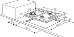
DIMENSIONSANDCLEARANCES
t
G0901/'_C901M
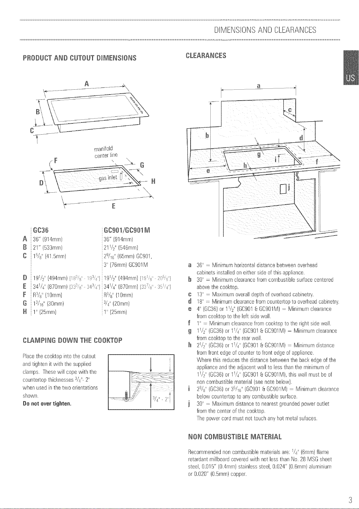
A 36" (914mm) 36" (914mm)
B 21" (533mm) 211/2'(546mm)
B 15/8' (41.5mm) 29/16' (65ram)6C901,
3' (76ram)66901M
#
E
F
G
191/2, (494mm)[18s/6'' 9:_//'] 191/2' (494mm)[9/,6 '' 20J/8'']
34V4' {870ram)[33:;&'' 34:_,',:"}34V4' (870ram)['/37& '' 3_?/4"
R9/8' (10ram) Rg/s' (10ram)
19/16' (30ram) 3/4'(20ram)
1' (25ram) 1' (25ram)
CLAM?_NG #OWN TNE COOKTO?
Placethecooktopintothecutout
andtightenitwith thesupplied
damps. Thesewill copewith the
countertopthicknesses3/4'-2'
whenusedinthetwo orientations
shown.
[}o not evertighten.
a 36' - Minimumhorizontaldistancebetweenoverhead
cabinetsinstalledoneithersideofthis appliance.
b 30' - Minimumclearancefromcombustibbsurfacecentered
abovethe cooktop.
o 13' - Maximumoveralldepthof overheadcabinetry.
18' - Minimumclearancefromcountertoptooverheadcabinetry.
e 4' (G636)or 11/2' (GC9018 66901M) - Minimumclearance
from cooktoptothe left sidewall.
f 1' - Minimumclearancefrom cooktopto therightsidewall.
g 1V2'(GC36)or1V4'(GC9018 6C901M)- Minimumclearance
from cooktoptothe rearwall.
h 21/2' (6C36)or 1V4'(6C90I 8 6C90IM) - Minimumdistance
fromfront edgeofcounterto frontedgeofappliance.
Wherethis reducesthedistancebetweenthebackedgeofthe
applianceandtheadiacentwallto lessthantheminimumof
1V2'(6C36)or 11/4"(6C9018 GC901M),this wall mustbe of
noncombustiblematerial{seenotebelow).
i 29/8' (GC36)or 35/16' (GC9018 Gcg01M)- Minimumclearance
belowcountertopto anycombustiblesurface.
i 30' - Maximumdistanceto nearestgroundedpoweroutlet
from thecenterofthe cooktop.
Thepowercordmustnottouchanyhot metalsufaces.
NON COMBUSTIBLE MATER_AL
Recommendednoncombustiblematerialsare:1/4'(6ram)flame
retardantmillboardcoveredwith not lessthanNo.28 MS6sheet
steel,0.015"(0.4ram)stainlesssteel,0.024"(0.6ram)aBminium
or 0.020"(0.5ram)copper.
INS ,S,LLA]IONINSTRUCTIONS
BEFOREYOU START _AS SUPPLYCO_/ECT_O_
@ Ensurethe countertopissquareandlevelandensureno
structuralmembersinterferewith spacerequirements.
@ Ensurethat thereisa powersupplyreceptacle(I 10-120V60Hz)
within reachofthe cooktoppowercord(30'fromthe middleof
theproduct).Themaincableshouldnottouchanyhotmetalparts.
@ Makesurethecooktopisconnectedto a powersupplysocket
that iselectricallygroundedin accordancewith localcodesor
in theabsenceoflocalcodes,with the NationalElectricCode
ANSI/FPA70or CSA22.2(Canada).
@ Makesurethecountertopismadeof aheatresistantmaterial.
@ Werecommendthat theexposedbarewoodedgesofthe
cutoutbesealedwith anoil basedpaintor moistureproof
polyurethaneto preventpossibledamagefrom moisture
creepingbetweenthe cooktoptrim andthe benchtop.
@ Werecommendusingeasy-to-cleanfinishesforthewall
surfacessurroundingthe cooktopto aidremovalofanycooking
stainsresultingfromuseofthecooktop.
@ Thisappliancecanbe usedwith eitherLPgasor Naturalgasand
isfacter_ set for rise with _at_ral flas.
@ A manualshut-offvalvemustbe installedinanaccessible
locationinthe gaslineexternalto theappliancefor thepurpose
ofturningon orshuttingoff gastotheappliance.(In
Massachusettssuchshutoffdevicesshouldbe approvedbythe
BoardofStateExaminersof Plumbers8GasFitters).
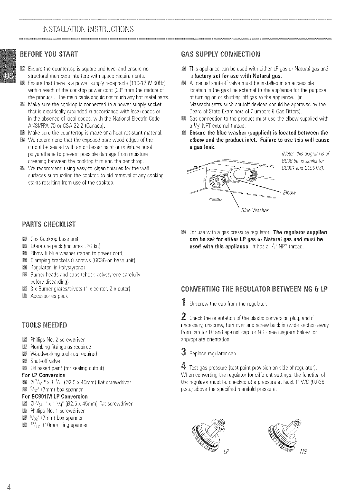
_;26asconnectionto theproductmustusetheelbowsuppliedwith
a _/2'NPTexternalthread.
@ Ensurethe b_e washer (s_pplied) is _ocatedbetween the
elbow and the predict inlet. FaiI_rete _se this will cause
a gas _eak.
@ore:thisdiagramisof
6636butissimilarfor
66901and68901M/,
Elbow
PA_TS C_EC_L_ST
@ GasCooktopbaseunit
@ Literaturepack(includesLP6kit)
@ Elbow8 bluewasher(tapedto powercord)
@ Clampingbrackets8 screws(6C36-0nbaseunit)
@ Regulator(inPolystyrene)
_d2Burnerheadsandcaps(checkpolystyrenecarefully
beforediscarding)
@ 3 x Burnergrates/trivets(1 xcenter,2 x outer)
_d2Accessoriespack
TOOLS_EEBEB
@ PhillipsNo.2 screwdriver
@ Plumbingfittingsasrequired
@ Woodworkingtoolsasrequired
@ Shut-offvalve
_2 Oilbasedpaint(forsealingcutout)
For LPConversion
@ O7/64' x 13/4'(@2.5x45ram)flat screwdriver
_2 9/32'(7ram)boxspanner
For GC901@ LPConversion
@ _ 7/64"x 1a/4"(@2.5x 45mm)flat screwdriver
@ PhillipsNo. 1 screwdriver
@ 9/32"{Tram)boxspanner
@ ls/32'(1gram)ringspanner
BlueWasher
@ Forusewith a gaspressureregulator.The regulator s_pplie_
can be set for either LPgas er _at_ral _asand _st be
use_ with this appliance, it hasa 1/2'NPTthread.
CO_VEBT_G T_E BE_ULATOB BETWEE_ _ 8 LP
1 Unscrewthe capfromthe regulator.
2 Checkthe orientationoftheplasticconversionplug,andif
necessary,unscrew,turnoverandscrewbackin {widesectionaway
from capfor LPandagainstcapforNG- seediagrambelowfor
appropriateorientation.
3 Replaceregulatorcap.
Testgaspressure(test pointprovisionon sideofregulator).
Whenconvertingtheregulatorfor differentsettings,thefunctionof
theregulatormustbe checkedata pressureat least1' WC(0.036
p.s.i.)abovethe specifiedmanifoldpressure.
INSTALLATIONINSTRUCTIONS
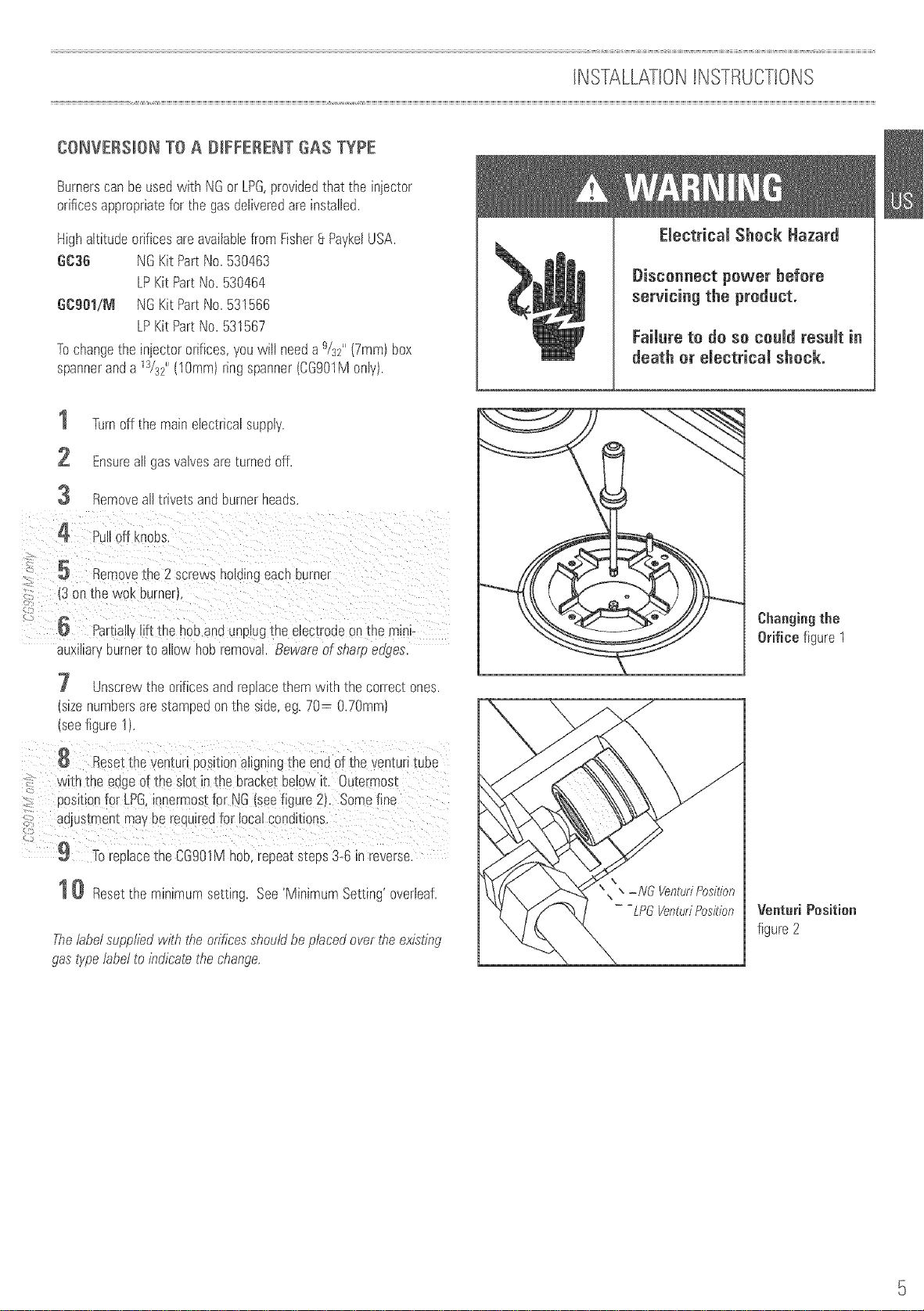
CONVERSIONTO A #_FFERENTGAS TYPE
Burnerscanbeusedwith N6 or LP6,providedthatthe iniector
orificesappropriatefor thegasdeliveredareinstalled.
HighaltitudeorificesareavailabbfromFisher8 PaykelUSA.
GC36 NGKitPartNo.530463
LPKitPartNo.530464
GC901/M NGKitPartNo.531566
LPKitPartNo.531567
Tochangetheiniectororifices,youwill needa 9/32' (7ram/box
spanneranda Is/s2'(10ram)ringspanner(C6901Monly}.
Dectrica_ Sheck Hazard
Discennect pewer befere
servicing the preduct.
Failure te do se could result in
death er ebetrieal shock.
1 Turnoff the main ebctrical supply.
2 Ensureall gas valves are turned off.
Remove all trivets and burner heads.
Pulloff Knobs.
Removethe 2 screws notqmgeacnburner
(3 on me WOKDL,qerl.
Par_:_a. lift the hoban{]unD g mee_ec[ror_eor theF""
auxmaryburner[o aHo_,_nodremoval.Bewareofsharpeoges.
7 Unscrewthe ori%esandreplacethemwith thecorrectones.
(sizenumbersarestampedonthe side,eg.70- 0.70mm)
(seefigureI).
Withthe edgeOftheSlotinthe bracketbelowit. Outermost
qb
::; positionfor L?G,innermostfor N6{s_efigure2). Somefine
Toreplacethe06901M hob,repeatsteps3-_6inreverse.
1 _ Resettheminimumsetting. See'MinimumSetting'overleaf.
Thelabelsupp//adwiththeorificesshouldbeplacedovertheexisting
gastypelabelto indicalethechange.
Venturi Pesitbn
figure2
INSTALLA£IONINSTRUCTIONS
LEA_ TEST_
_J Leaktestingof theapplianceshallbe conductedaccordingto
themanufactureCsinstructions.
_d2Theapplianceandit's individualshutoffvalvemustbe
disconnectedfromthe gassupplypipingsystemduringany
pressuretestingofthat systeminexcessof _/2p.s.i.(3.SkPa}.
_d2Theappliancemustbeisolatedfrom thegassupplypiping
systembyclosingit's individualmanualshutoffvalveduringany
pressuretestingofthegassupplypipingsystemat test
pressuresat or lessthan_/2p.s.i.(3.SkPa/.
_J Maximuminletgassupplypressure4' W.C.Natural6as,
11'W.C.LPgas.
_2 Minimumgassupplypressurefor regulatortesting5' W.C.
NaturalGas,12'W.C.LPgas.
After installingthe gassupplyandmakingall connectionscheck
thoroughlyforpossibleleaks.
I Turnall controlknobsonunitto 'off' position.
2 Openthevalveon thegassupply.
3 Usinga leakdetectionfluid (e.g.Rocolleakdetectionspray)
checkeachgasconnectiononeat atime bybrushingthesolution
overtheconnection.Thepresenceofbubbleswill indicatea leak.
4 If necessary,tightenthefittingandrecheckfor leaks.
5 Turnonburnervalveandlighteachburner.
6 Checkfora clearblueflamewithoutyellowtipping. If burners
showanyabnormalities,checkthat theyarelocatedpropedyandin
linewith theiniectororifice.
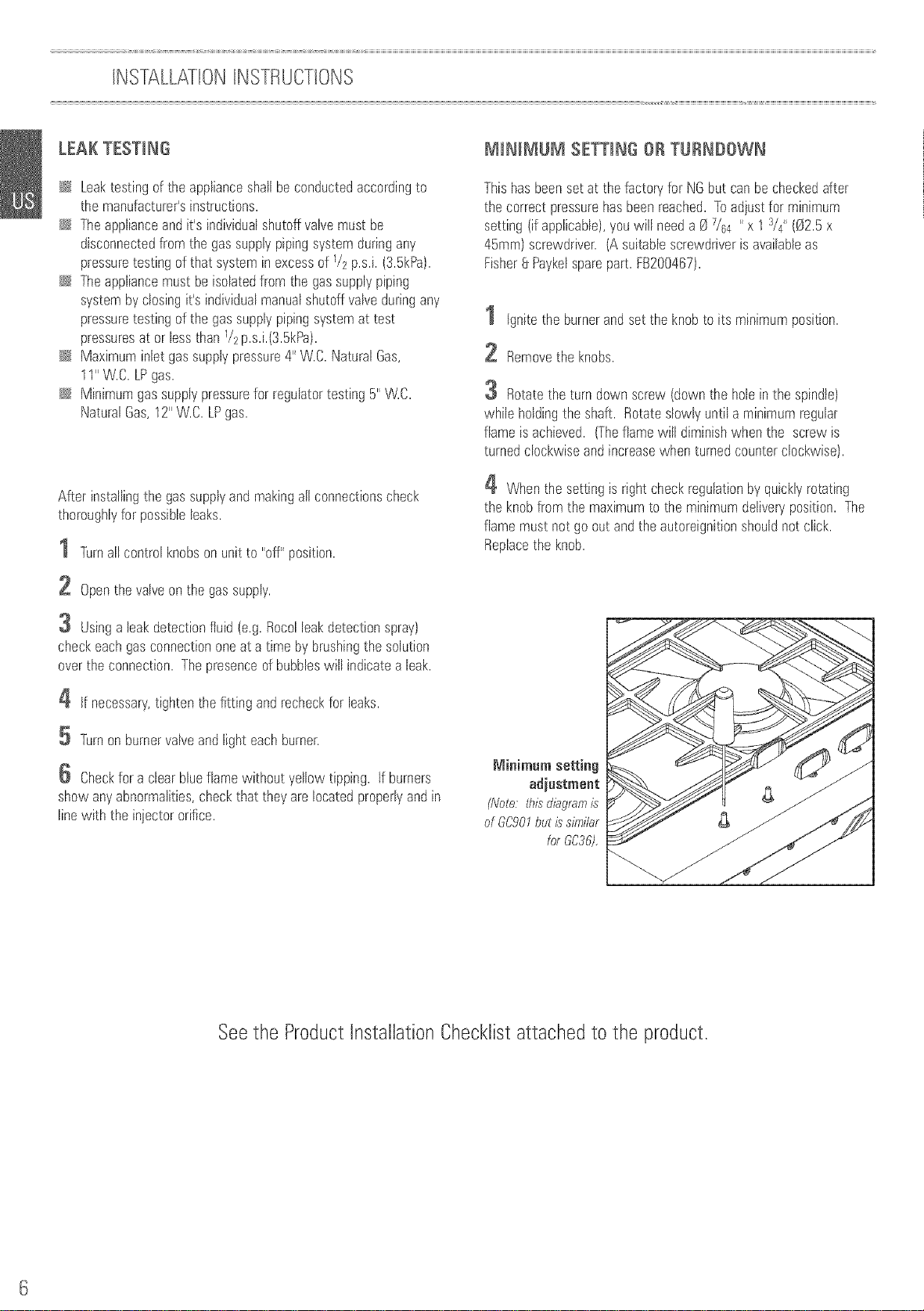
M_MUM SETTinG OB TUB_BOW_
Thishasbeensetat thefactoryforNGbutcanbecheckedafter
thecorrectpressurehasbeenreached.Toadiustfor minimum
setting(ifapplicable),youwill needa_ 7/64' x 13/4"(_2.5x
45mm)screwdriver.(Asuitablescrewdriverisavailableas
Fisher8 Paykelsparepart.FB200467).
ignitetheburnerandset theknobto its minimumposition.
2 Removetheknobs.
Rotatethe turndownscrew(downtheholeinthe spindle)
whileholdingtheshaft. Rotateslowlyuntila minimumregular
flameisachieved.{Theflamewill diminishwhenthe screwis
turnedclockwiseandincreasewhenturnedcounterclockwise).
Whenthe settingisrightcheckregulationbyquicklyrotating
theknobfromthemaximumto theminimumdeliveryposition.The
flamemustnotgo outandtheautoreignitionshouldnotdick.
Replacethe knob.
_i_i_r_ setting
a_i_stme_t
(Note: thisdiagramis
of 68901but issimilar
forG836),
See the Product Insta%tionChecklist attached to the product.
INSTALLATIONINSTRUCTIONS
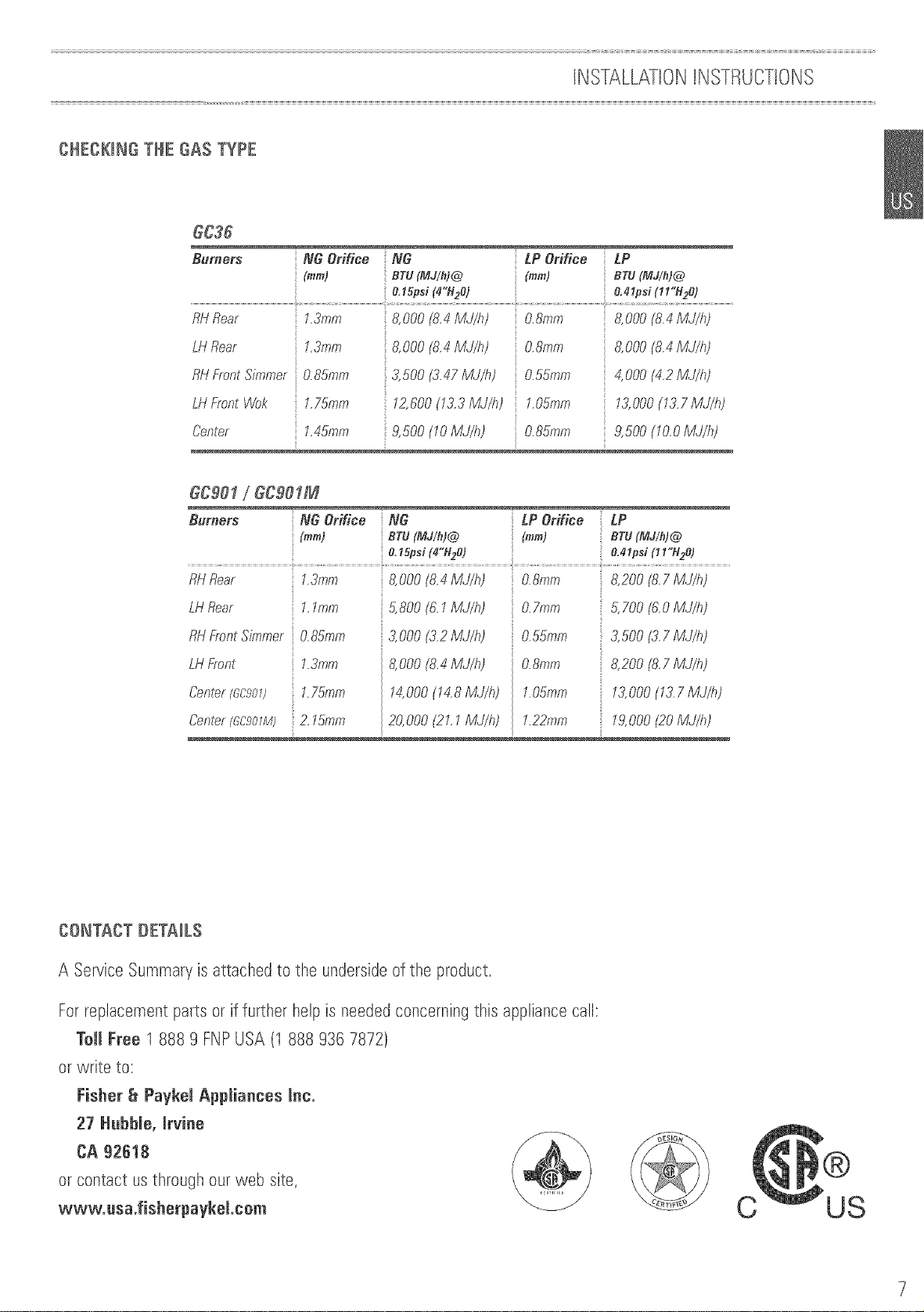
CHECKING THE GAS TYPE
Burners NG Orifice NG LP Brifiee LP
(ram) BTU (MJ/h)@ (ram) EtTU(MJ/h)@
o.15psi(4"_o) ompsi (11"_o)
RHRear
LHRear
RHFrontSimmer
LBFrontWok
1.3ram
1.3ram
O.85ram
I. 75ram
8,000(8.4IW/h)
8,ooo(84
i
3,500(8.47MJ/h)
12,000(13.3_J/h)
0.Smm 8,000(8.4l_J/h)
0.Smm 8,000(8.4MJ/h)
0.55ram ,, 4,000(4.2MJ/h)
1.05mm 13,000(13.71W/h)
Center 1.45mm 9,500(10MJ/h) O.85mm 9,500(10.0tvU/h)
GC901 / GCg01M
Burners NG Orifice NG LP Orifice LP
(ram) BTU (MJ/h)@ (ram) BTU (MJ/h)@
O.15psi (4"_20) O,#l psi (11"_20)
RHRear 1.3ram 8,000(8,4/_J/h) 0.Smm 8,200(8.7_J/h)
LHRear 1.1ram 5,800(G.I MJ/N 0.7ram 5}700(0.0/_J/h)
RHFrontSimmer 0.85ram 3,000(8.2_J/N 0.55mm 3,500(8.7_J/h)
LHFront 1.3ram 8,000(8.4l_J/h) 0.Smm 8,200(8.7l_J/h)
Center£c_o_} 1.75mm 14,000(14.8l_J/h) 1.05ram 13,000(I3.7 l_J/h)
Center(GC_O_M}2.15ram 20,000(2I. 1Mg/h) 1.22mm 19,000(20MJ/h)
CONTACT #ETA&S
A ServiceSummaryis attached to the undersideof the product.
Forreplacementparts or if further helpis neededconcerningthis appliance call:
Tell Free t 888 9 FNPUSA (1 888 936 7872)
or write to:
Fisher 8 Pa_kel Appliances _ac.
27 Habble, _rviae
CA 92618
or contact usthrough our web site,
www.asa.fis_erpaykeLcem
C
®
US