
Loading ...
Loading ...
Loading ...
13
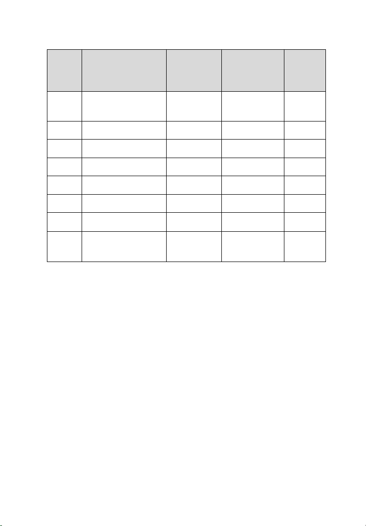
Table 2-5 Definitions of EEPROM Clamp Cable
No.
Color
Definition
Pin
correspond
to DB15
Note
10
White and Red
P1
5
Pin 1 is
red
11
White and Purple
P2
15
12
White and Blue
P3
10
13
Grey
P4
4
14
White and Brown
P5
14
15
White and Green
P6
9
16
White and Orange
P7
3
17
White and Black
P8
13
Pin 8 is
black
Here are the possible causes for EEPROM read/write failure and data error
when connecting the clamp to the test board for EEPROM read/write:
A. EEPROM read/write operations are affected by the circuit of the
connected test board;
B. EEPROM read/write operations of the test board are affected by the
read/write operations of the clamp;
C. The signal is damaged by large resistance. A large resistance will be
generated when connecting the clamp to a fast communicating
EEPROM or using a long cable for connection.
Therefore, it is recommended to dismantle the chip on the EEPROM, weld
the EEPROM to the EEPROM adaptor or place in the EEPROM socket, and
then insert it in the EEPROM adaptor.
18. EEPROM Clamp
19. DB15 VGA Port
EEPROM Adaptor
Loading ...
Loading ...
Loading ...