Loading ...
Loading ...
Loading ...
F A UR S
CONTROL PANEL FEATURES
,
,
3.
,
,
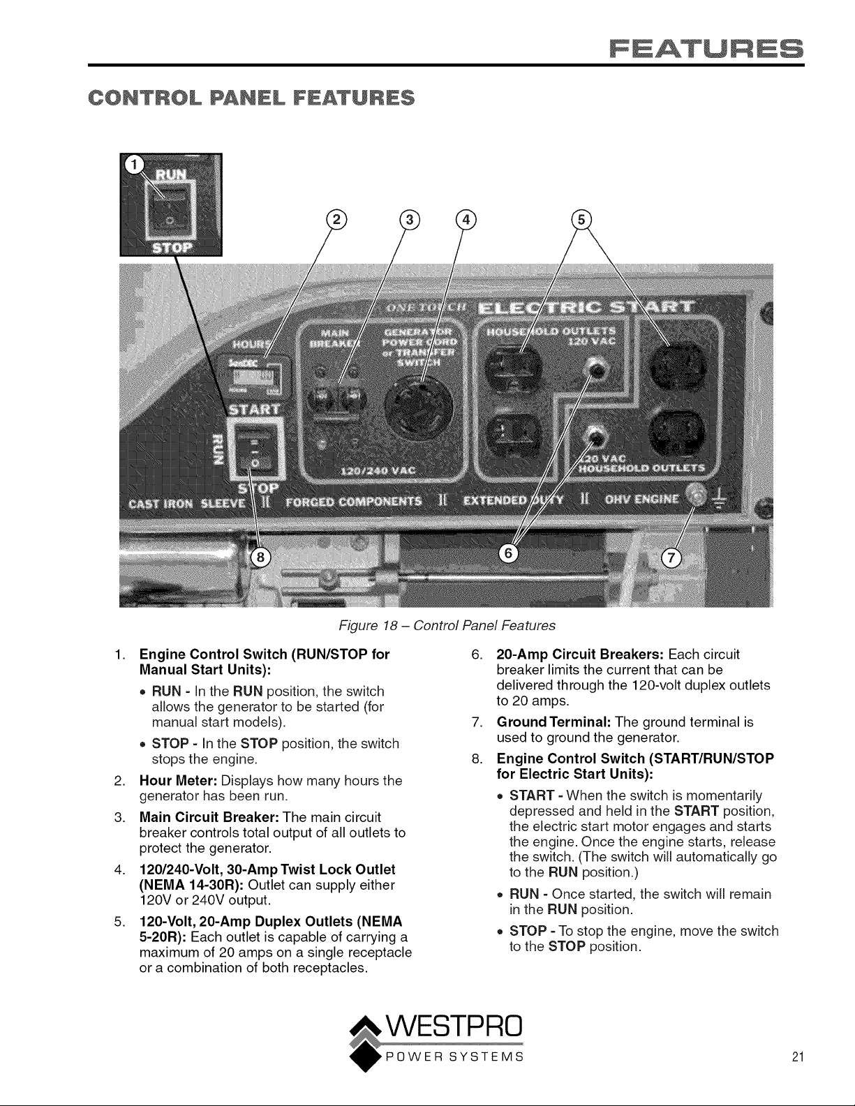
Figure 18 - Control Panel Features
Engine Control Switch (RUN/STOP for
Manual Start Units):
• RUN - In the RUN position, the switch
allows the generator to be started (for
manual start models).
• STOP - In the STOP position, the switch
stops the engine.
Hour Meter: Displays how many hours the
generator has been run.
Main Circuit Breaker: The main circuit
breaker controls total output of all outlets to
protect the generator.
120/240-Volt, 30-Amp Twist Lock Outlet
(NEMA 14-30R): Outlet can supply either
120V or 240V output.
120-Volt, 20-Amp Duplex Outlets (NEMA
5-20R): Each outlet is capable of carrying a
maximum of 20 amps on a single receptacle
or a combination of both receptacles.
,
,
8.
20-Amp Circuit Breakers: Each circuit
breaker limits the current that can be
delivered through the 120-volt duplex outlets
to 20 amps.
Ground Terminal: The ground terminal is
used to ground the generator.
Engine Control Switch (START/RUN/STOP
for Electric Start Units):
• START - When the switch is momentarily
depressed and held in the START position,
the electric start motor engages and starts
the engine. Once the engine starts, release
the switch. (The switch will automatically go
to the RUN position.)
• RUN - Once started, the switch will remain
in the RUN position.
• STOP - To stop the engine, move the switch
to the STOP position.
21
Loading ...
Loading ...
Loading ...