Loading ...
Loading ...
Loading ...
PAGE:10 / 12
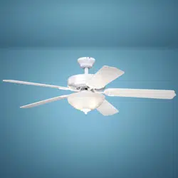
Connect the white (neutral)
wire from motor to the white
(neutral) wire from the
outlet box with a wire
connector.
Connect the black (hot) wire
(This is for fan control) and blue
wire (This is for light control) from
motor to the black (hot) wire from
outlet box with a wire connector.
Bla
Black
ck
Blue
Green
White
White
Grounding
Green
*** After making the wire connections, the wires should
be spread apart. The white (neutral) conductor and
green (grounding) conductor on one side and the
black (hot) conductor and blue (light) conductor on
the other side of the outlet box.
*** The wire connection points should be turned upward
and pushed carefully up into outlet box.
Connect three
ground wires (Green
or bare copper) coming
from outlet box,
downrod and hanging
bracket with a wire
connector.
For a single switch
Follow these steps:
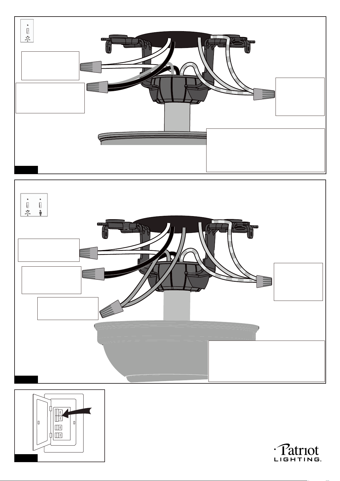
Connect three
ground wires (Green
or bare copper) coming
from outlet box,
downrod and hanging
bracket with a wire
connector.
Connect the black (hot) wire
from motor (This is for fan
control) to the black (hot)
wire from outlet box with a
wire connector .
Green
Black
Blue
Green
White
Black
Blue
(light)
White
Grounding
Connect the white (neutral)
wire from motor to the white
(neutral) wire from outlet box
with a wire connector .
Connect the blue wire (This
is for light control) from motor
to the blue wire from outlet
box with a wire connector.
*** The wire connection points should be turned
upward and pushed carefully up into outlet box.
Turn ON the electric circuit at the main fuse or circuit breaker box.
For dual switches
Follow these steps:
*** After making the wire connections, the wires should
be spread apart. The white (neutral) conductor and
green (grounding) conductor on one side and the
black (hot) conductor and blue (light) conductor on
the other side of the outlet box.
Fig.27
Fig.28
Fig.29
220104
Loading ...
Loading ...