Loading ...
Loading ...
Loading ...
ASSEMBLY
If unit is received assembled, repeat all steps in this section to be sure assembly is correct and is ad-
justed for the operator.
This Operator's Manualis designed to help you assemble the tool and to provide its safe operation. It is important
that you read the entire manual to :become familiar with the toolbefore you begin assembly.
The only tool needed for assembly is a Phillips screwdriver.
............... ,,,,, ,i i ill i tmmt iv ................
A.TUBE & SHIELD ATTACHMENT
A WARNING
The shield must be properly instaHe& The
shield reduces the risk of _ from thrown ob-
jects. Failure to install the shi.'eIdin the position
shown in Figt_rc 1 canresult mi_ury to the op-
erator or others. Carefully follow assem]_y in-
structions when attaching shield to unit. The
operator should always wear e_e protection.
1. Remove the scTewa from the plestic bag.
2. Remove the top screw andnutin the sphidle hous-
ing and loosen the second screw. Figure 1.
3. Insert the flex sha_ through either end of the
tube. Figure 1.
4. Position the crease in the end ofthe tube as shown
in Figure 1. Slide the tube into the spindle hous-
ing until the erease is aligned with the top screw
hole in the spindle housing.
The dimple in the tube (Figure 1 ) will no
longer he visible if t_be is fully inserted.
5. Instal! the top screw and nut (removed in step 2.).
Tighten both upper screws securel_
The shietd is equipped with a line
limiter (on the underside of the Shield) which
_uts line to the proper length, The llne llmiter
is sharp and can cut you.
6. Place the shield over the flex sha_ then over the
spindle housing. Figure 1. Slide the shield into
position Figure I.
7. Align the hdes on the shield with the holes in the
spindle heusing.
8. Thread the screws into the spindle housing. Fig.
ure 1. Tighten screws securbly.
B.ASSIST HANDLE ATTACHMENT
1. Slide the assist handle onto the tube (approxi-
mately helfway down the tube). Figure I.
2. Insert the heir through the bolt hole in the assist
handle. Figare 1.
3. Placethewasheronthebolt, thenthreadthekneb
onto the bolt, Figur e 1. Tighte_ the knob just
enough to hold the parts together.
C. MOTO_GGER HOUSING
• ASSEMBLY
I. Loosen knob and front screw on the trigger hous-
ing. Figure 1.
2. Remove the front screw and nut in the motor
housing and loosen the second screw, Figure I.
3. Insert the tube throughthe triggerhousinga_
ser_bly; _ 1. Then slide tKe tube into the
The _e_ headmighth_vetobe rot,_l
• slightly to allow the tube to sIide completely into
the motor housing. ' •
4. Align the crease in the tube with the front screw
hole in the motor housing. Figure 1,
5, Install the front screw and nut in the motor housu
ing. Tighten both front screws securely.
6, Adjust the trigger housing and assist handle for
balance and comfort, Securely tighten the knobs
and screws.Figure I.
i cAUT!ON:I To reduce the risk of eleetrieal
shock, do not twist the cord around the tube.
Remove the protective c_vering from the line
limiter before operatingyourtrimmer.
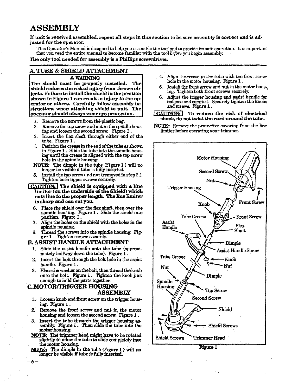
TriggerHousing
Front Screw
Tube Crease_I Front Screw
Assist
_dle Flex
S_aft
_andle Screw
Tube Crease _ _ Knob
Nut "_'_"_" Nut
x_ DimpIe
Spindle
Second Screw
Loading ...
Loading ...
Loading ...