Loading ...
Loading ...
Loading ...
HAIRPIN
COTTER
\
- LIFT LEVER SUPPORT i
.-,-BRACKET
3/8" X 1"---_---_ ]
HEX BOLTS ---'=_, -,
,_3/8"_HEX'I2OCK NUTS -_.
UP STOP BRACKET
T
HANDLE
GUIDE
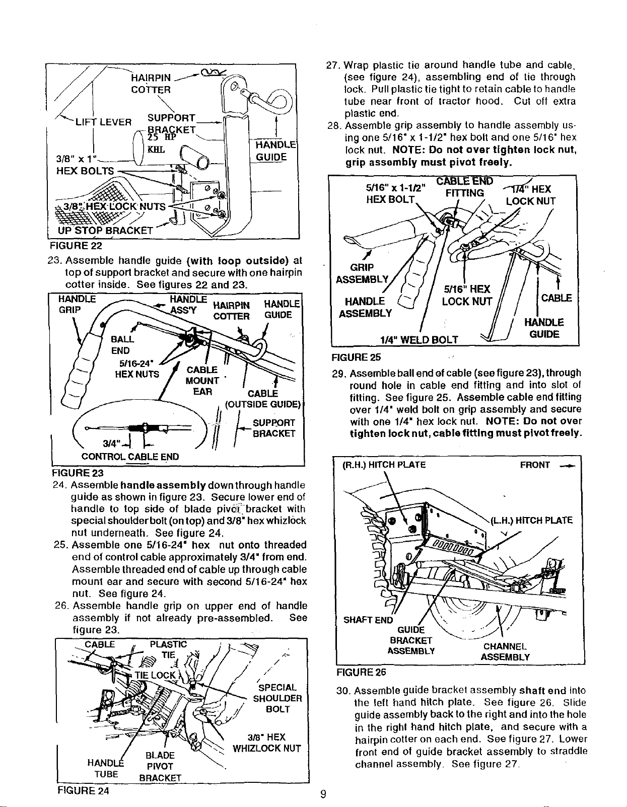
FIGURE 22
23. Assemble handle guide (with loop outside) at
top of support bracket and secure with one hairpin
cotter inside. See figures 22 and 23.
HANDLE HANDLE HAIRPIN HANDLEI
GRIP
COTTER GUIDE
I 3/4"._CONTROLCABLEEND
FIGURE 23
CABLE
(OUTSIDE GUIDE'
LSUPF_ORT
-BRACKET
24. Assemble handleassemblydownthrough handle
guide as shown in figure 23. Secure lower end of
handle to top side of blade pive_ bracket with
special shoulder bolt (on top) and 3/8" hex whizl0ck
nut underneath. See figure 24.
25. Assemble one 5/16-24" hex nut onto threaded
end of control cable approximately 3/4" from end.
Assemble threaded end of cable up through cable
mount ear and secure with second 5/16-24" hex
nut. See figure 24.
26. Assemble handle grip on upper end of handle
assembly if not already pre-assembled. See
figure 23.
CABLE PLASTIC
/
/
//
#
SPECIAL
SHOULDER
BOLT
BLADE
HANDI_I_ PIVOT
TUBE BRACKET
3/8" HEX
WHIZLOCKNUT
27. Wrap plastic tie around handle tube and cable,
(see figure 24), assembling end of tie through
lock. Pull plastic tie tight to retain cable to handle
tube near front of tractor hood. Cut oft extra
plastic end.
28. Assemble grip assembly to handle assembly us-
ing one 5/16" x 1-1/2" hex bolt and one 5/16" hex
lock nut. NOTE: Do not over tighten lock nut,
grip assembly must pivot freely.
CABLE END f3_"HEX
5/16" x 1-1/2" FFn'ING
HEX BOLT LOCK NUT
/
GRIP
ASSEMBLY
HANDLE
ASSEMBLY
114"WELD BOLT
HANDLE
GUIDE
FIGURE 25
29. Assemble ball end of cable (see figure 23), through
round hole in cable end fitting and into slot of
fitting. See figure 25. Assemble cable end fitting
over 1/4" weld bolt on grip assembly and secure
with one 1/4" hex lock nut. NOTE: Do not over
tighten lock nut, cable fitting must pivot freely.
(R.H.) HITCH PLATE FRONT
L.H.) HITCH PLATE
SHAFT END
GUIDE
BRACKET
ASSEMBLY
FIGURE 26
CHANNEL
ASSEMBLY
30. Assemble guide bracket assembly shaft end into
the left hand hitch plate. See figure 26. Slide
guide assembly back to the right and into the hole
in the right hand hitch plate, and secure with a
hairpin cotter on each end. See figure 27. Lower
front end of guide bracket assembly to straddle
channel assembly. See figure 27.
FIGURE 24 9
Loading ...
Loading ...
Loading ...