Loading ...
Loading ...
Loading ...
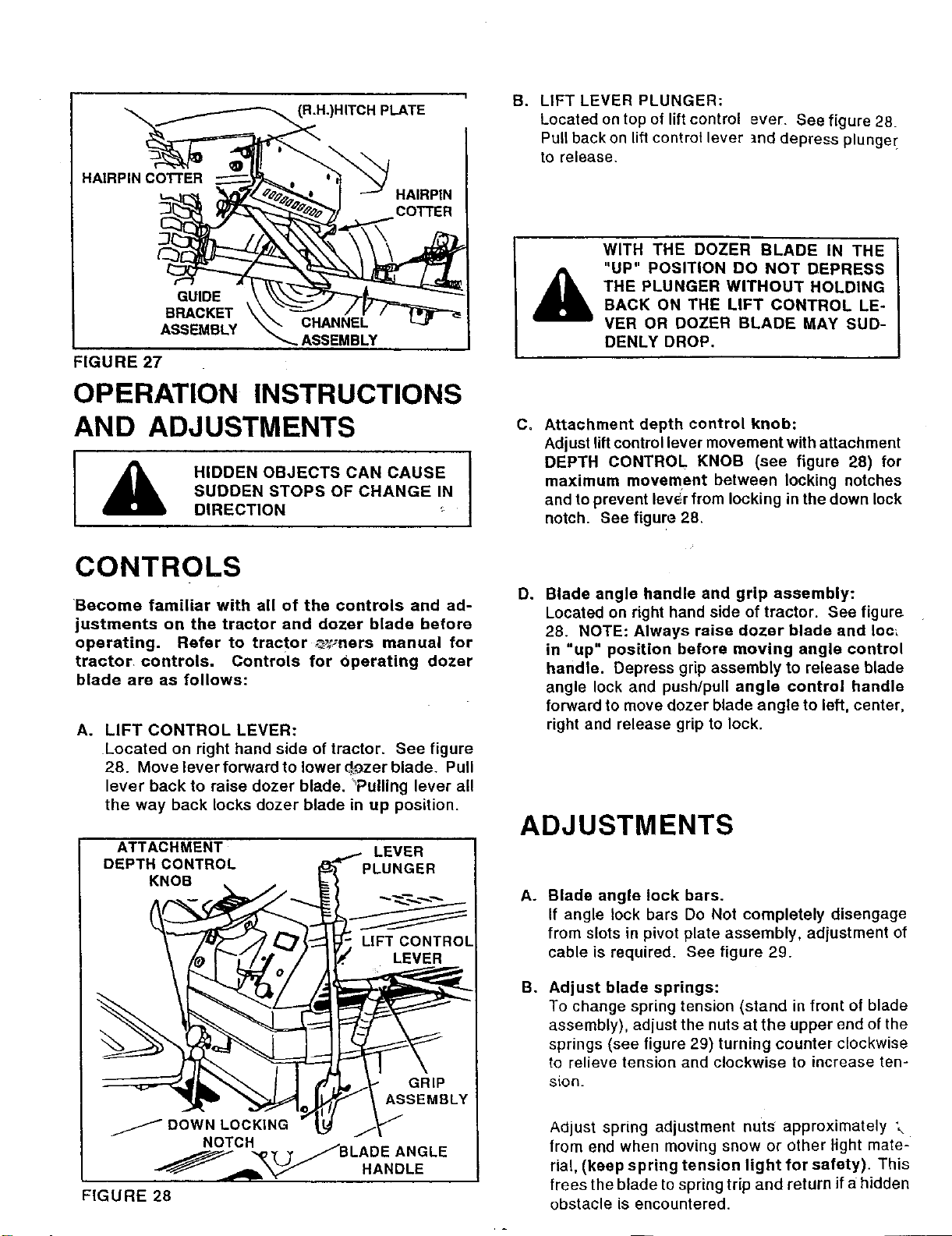
HAIRPIN COTTER
(R.H.)HITCH PLATE
HAIRPIN
COTTER
B. LIFT LEVER PLUNGER:
Located on top of lift control ever. See figure 28.
Pull back on lift control lever tnd depress plunger
to release.
GUIDE
BRACKET \
ASSEMBLY
FIGURE 27
CHANNEL
-_ ASSEMBLY
OPERATION INSTRUCTIONS
AND ADJUSTMENTS
I _ HIDDEN OBJECTS CAN CAUSE
SUDDEN STOPS OF CHANGE IN
DIRECTION
CONTROLS
WITH THE DOZER BLADE IN THE
"UP" POSITION DO NOT DEPRESS
THE PLUNGER WITHOUT HOLDING
BACK ON THE LIFT CONTROL LE-
VER OR DOZER BLADE MAY SUD-
DENLY DROP.
C. Attachment depth control knob:
Adjust lift control lever movement with attachment
DEPTH CONTROL KNOB (see figure 28) for
maximum movement between locking notches
and to prevent lever from locking in the down lock
notch. See figure 28.
Become familiar with all of the controls and ad-
justments on the tractor and dozer blade before
operating. Refer to tractor ,_=,_ners manual for
tractor controls. Controls for Operating dozer
blade are as follows:
A. LIFT CONTROL LEVER:
Located on right hand side of tractor. See figure
28. Move lever forward to lower d_ozerblade. Pull
lever back to raise dozer blade, Pulling lever all
the way back locks dozer blade in up position.
ATTACHMENT
DEPTH CONTROL
KNOB
LEVER
D. Blade angle handle and grip assembly:
Located on right hand side of tractor. See figure
28. NOTE: Always raise dozer blade and Ioc_
in "up" position before moving angle control
handle. Depress grip assembly to release blade
angle lock and push/pull angle control handle
forward to move dozer blade angle to left, center,
right and release grip to lock.
ADJUSTMENTS
A_
B°
Blade angle lock bars.
If angle lock bars Do Not completely disengage
from slots in pivot plate assembly, adjustment of
cable is required. See figure 29.
Adjust blade springs:
To change spring tension (stand in front of blade
assembly), adjust the nuts at the upper end of the
springs (see figure 29) turning counter clockwise
to relieve tension and clockwise to increase ten-
sion.
Adjust spring adjustment nuts approximately \
from end when moving snow or other light mate-
rial, (keep spring tension light for safety). This
frees the blade to spring trip and return if a hidden
obstacle is encountered.
Loading ...
Loading ...
Loading ...