Loading ...
Loading ...
Loading ...
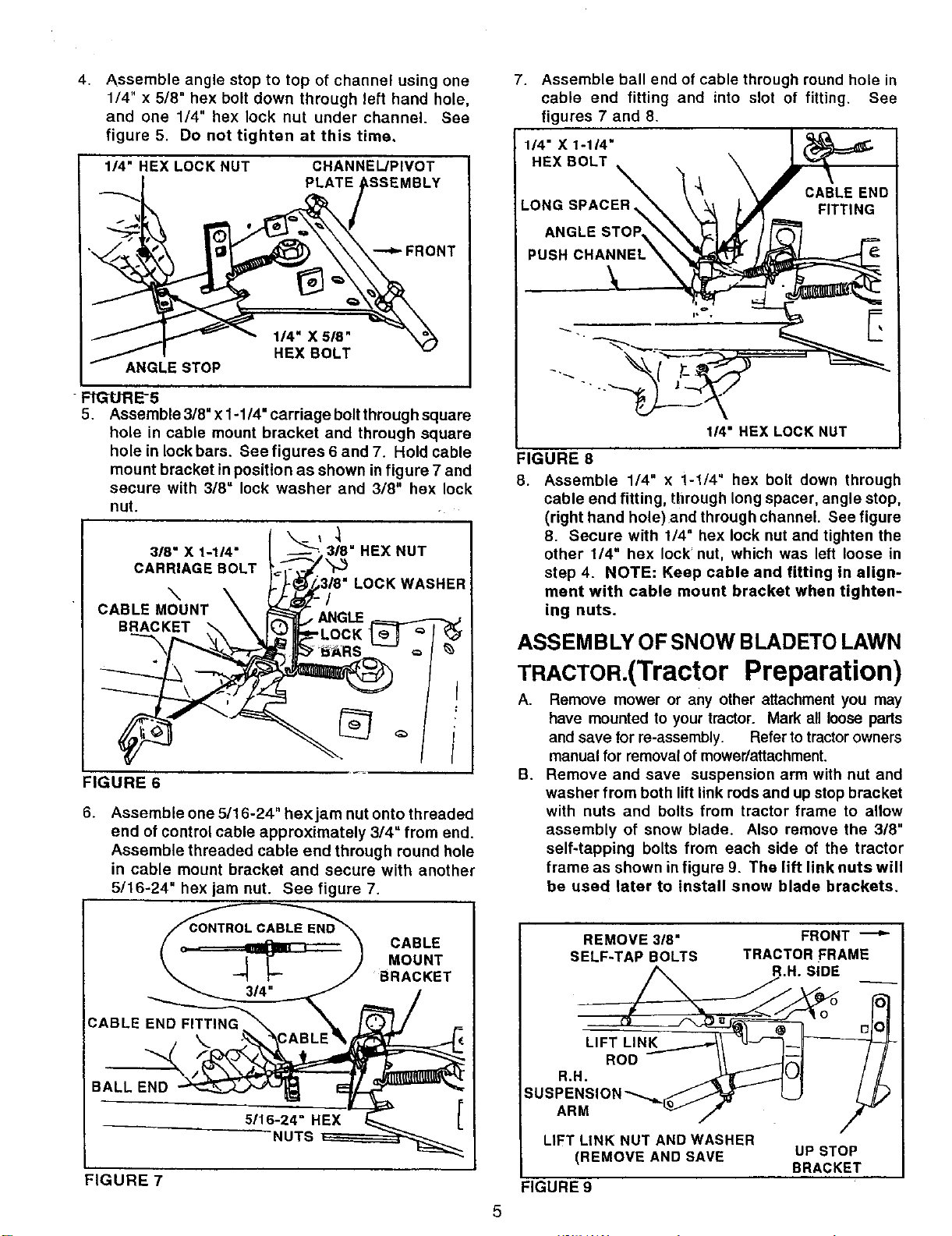
4.
Assemble angle stop to top of channel using one
1/4" x 5/8" hex bolt down through left hand hole,
and one 1/4" hex lock nut under channel. See
figure 5. Do not tighten at this time,
I_"HEX LOCK NUT CHANNEWPIVOT
PLATE _BLY
1/4" X 5/8"
HEX BOLT
ANGLE STOP
FIGURE-5
5. Assemble 3/8" x 1-1/4" carriage bolt through square
hole in cable mount bracket and through square
hole in lock bars. See figures 6 and 7. Hold cable
mount bracket in position as shown in figure 7 and
secure with 3/8= lock washer and 318" hex lock
nut.
318" X 1-114"
CARRIAGE BOLT
\
CABLE MOUNT
BRACKET
,1
318" HEX NUT
LOCK WASHER
FIGURE 6
6. Assemble one 5/16-24" hexjam nut onto threaded
end of control cable approximately 3/4" from end.
Assemble threaded cable end through round hole
in cable mount bracket and secure with another
5/16-24" hex jam nut. See figure 7.
CABLE
MOUNT
t BRACKET
,.°-..EX [
NUTS _
FIGURE 7
7. Assemble ball end of cable through round hole in
cable end fitting and into slot of fitting. See
figures 7 and 8.
1/4" X 1-1/4"
HEX BOLT
LONG SPACER
ANGLE STOP
CABLE END
FITTING
PUSH
1_" HEX LOCK NUT
FIGURE 8
8.
Assemble 1/4" x 1-1/4" hex bolt down through
cable end fitting, through long spacer, angle stop,
(right hand hole)and through channel. See figure
8. Secure with 1/4" hex lock nut and tighten the
other 1/4" hex lock nut, which was left loose in
step 4. NOTE: Keep cable and fitting in align-
ment with cable mount bracket when tighten-
ing nuts.
ASSEMBLY OF SNOW BLADETO LAWN
TRACTOR,(TractorPreparation)
A. Remove mower or any other attachment you may
have mounted to your tractor. Mark all loose parts
and save for re-assembly. Refer to tractor owners
manual for removal of mower/attachment.
B. Remove and save suspension arm with nut and
washer from both lift link rods and up stop bracket
with nuts and bolts from tractor frame to allow
assembly of snow blade. Also remove the 318"
self-tapping bolts from each side of the tractor
frame as shown in figure 9. The lift link nuts will
be used later to install snow blade brackets.
REMOVE 3/8"
SELF-TAP BOLTS
FRONT ---*"
TRACTOR FRAME
R.H. SIDE
5
ARM
LIFT LINK NUT AND WASHER
(REMOVE AND SAVE
FIGURE 9
UP STOP
BRACKET
Loading ...
Loading ...
Loading ...