Loading ...
Loading ...
Loading ...
18 | English
1 609 92A 0L0 | (16.5.14) Bosch Power Tools
To activate the automatic switch-off, switch the measur-
ing tool off and switch it on again by pressing briefly the
On/Off button 3. After the switching on, the laser lines do
not flash.
Angular accuracy
Influences on Accuracy
The ambient temperature has the greatest influence. Espe-
cially temperature differences occurring from the ground
upward can divert the laser beam.
Therefore, position the measuring tool as near as possible
to the work surface and fix it with the underside as parallel
as possible to the work surface.
Apart from exterior influences, device-specific influences
(such as heavy impact or falling down) can lead to devia-
tions. Therefore, check the accuracy of the measuring tool
each time before starting your work.
Checking the angular accuracy
For this check, you need a free surface of approx.
10 x 5 m on a stable and even base.
Should the measuring tool exceed the maximum deviation
during one of the tests, please have it repaired by a Bosch
after-sales service.
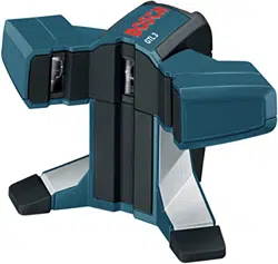
Checking the angular accuracy between the 0° and
the 90° laser lines
– Position the measuring tool in one of the corners of the
measuring surface. Switch on the measuring tool and
align it so that the 0° laser line runs along the long side
of the measuring surface and that the 90° laser line
runs along the short side of the measuring surface.
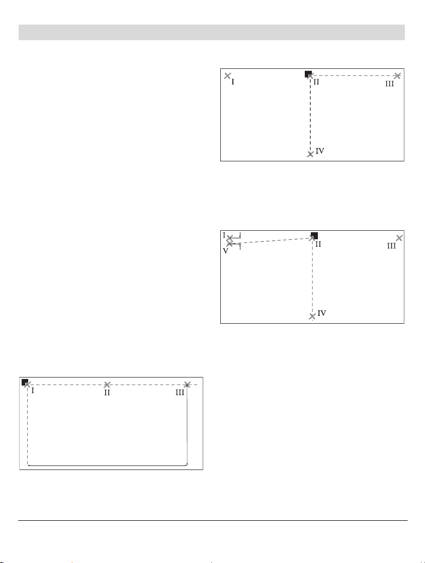
– Mark the crossing point of the laser lines on the floor
(Point I). Mark also the centre of the 0° laser line at a
distance of 5 m (Point II) and at a distance of 10 m
(Point III).
– Position the measuring tool (without turning it) at a dis-
tance of 5 m so that the crossing point of the laser lines
is on the already marked point II and that the 0° laser
line runs through the point III.
Mark the centre of the 90° laser line at a distance of
5m (PointIV).
– Turn the measuring tool by 90° so that the centre of the
0° laser line runs through the point IV.
The crossing point of the laser lines must still be on the
point II.
– Mark the centre of the 90° laser line at a distance of
5m as pointV as near as possible next to the point I.
– The difference d of the two points V and I is the actual
deviation of the 0° laser line and the 90° laser line from
the right angle.
The measuring length 2 x 5 m = 10 m has a maximum
admissible deviation of: 10 m x ±
0.2 mm/m = ±2 mm.
Therefore, the maximum difference d between the points
I and V may be 2 mm or less.
10 m
5 m
d
OBJ_BUCH-828-004.book Page 18 Friday, May 16, 2014 1:02 PM
Downloaded from www.ManualsFile.com manuals search engine
Loading ...
Loading ...
Loading ...