Loading ...
Loading ...
Loading ...
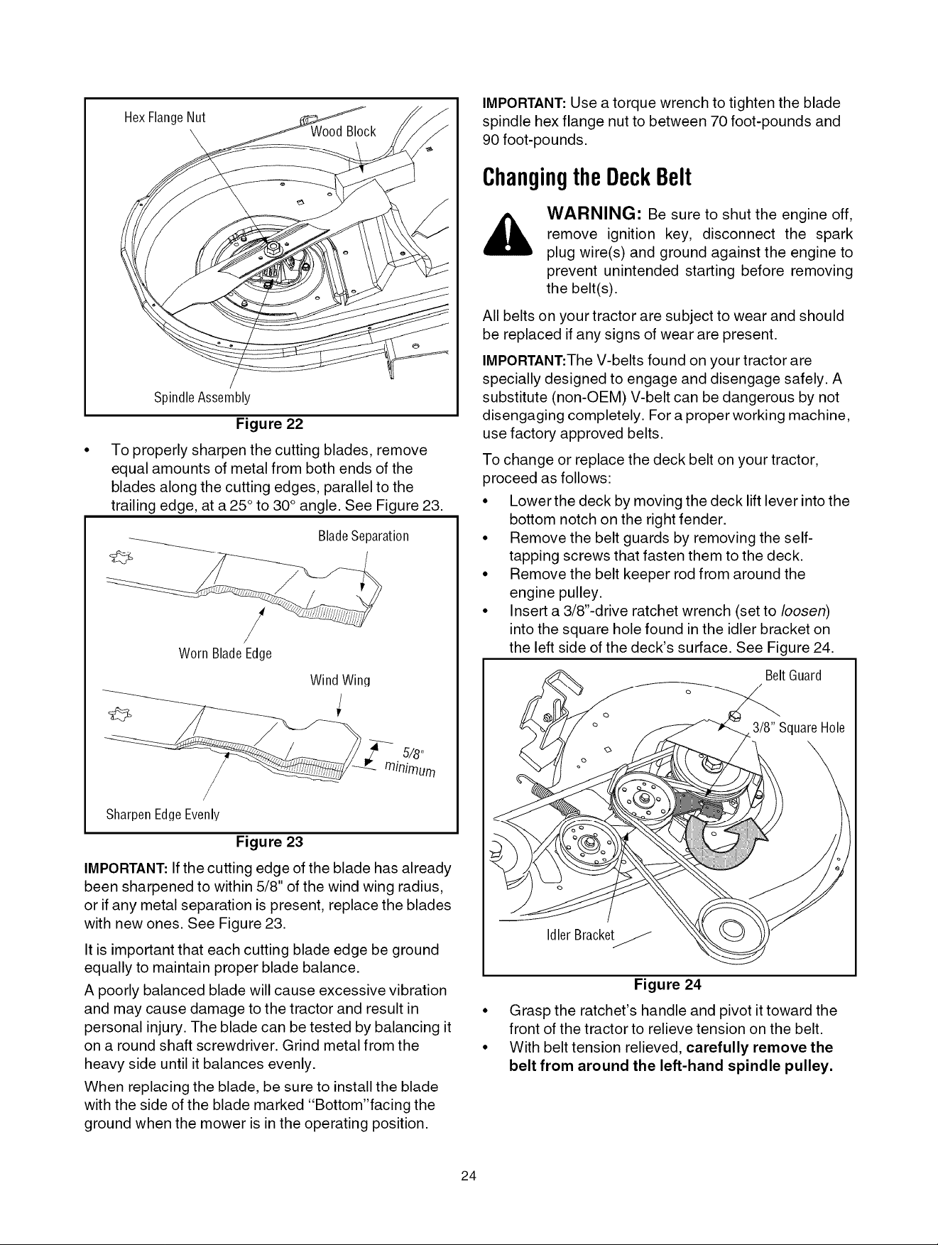
HexFlangeNut
SpindleAssembly
Figure 22
To properly sharpen the cutting blades, remove
equal amounts of metal from both ends of the
blades along the cutting edges, parallel to the
trailing edge, at a 25 ° to 30° angle. See Figure 23.
Blade Separation
/
/
WornBladeEdge
Wind Wing
/
SharpenEdgeEvenly
Figure 23
IMPORTANT: Ifthe cutting edge of the blade has already
been sharpened to within 5/8" of the wind wing radius,
or if any metal separation is present, replace the blades
with new ones. See Figure 23.
It is important that each cutting blade edge be ground
equally to maintain proper blade balance.
A poorly balanced blade will cause excessive vibration
and may cause damage to the tractor and result in
personal injury. The blade can be tested by balancing it
on a round shaft screwdriver. Grind metal from the
heavy side until it balances evenly.
When replacing the blade, be sure to install the blade
with the side of the blade marked "Bottom"facing the
ground when the mower is in the operating position.
IMPORTANT:Use a torque wrench to tighten the blade
spindle hex flange nut to between 70 foot-pounds and
90 foot-po unds.
ChangingtheDeckBelt
WARNING: Be sure to shut the engine off,
remove ignition key, disconnect the spark
plug wire(s) and ground against the engine to
prevent unintended starting before removing
the belt(s).
All belts on your tractor are subject to wear and should
be replaced if any signs of wear are present.
IMPORTANT:The V-belts found on your tractor are
specially designed to engage and disengage safely. A
substitute (non-OEM) V-belt can be dangerous by not
disengaging completely. For a proper working machine,
use factory approved belts.
To change or replace the deck belt on your tractor,
proceed as follows:
• Lower the deck by moving the deck lift lever into the
bottom notch on the right fender.
• Remove the belt guards by removing the self-
tapping screws that fasten them to the deck.
• Remove the belt keeper rod from around the
engine pulley.
• Insert a 3/8"-drive ratchet wrench (set to loosen)
into the square hole found in the idler bracket on
the left side of the deck's surface. See Figure 24.
Belt Guard
Idler Bracket_
Figure 24
• Grasp the ratchet's handle and pivot it toward the
front of the tractor to relieve tension on the belt.
• With belt tension relieved, carefully remove the
belt from around the left-hand spindle pulley.
24
Loading ...
Loading ...
Loading ...