

www.PyleUSA.com2
Please read this manual for proper operation
and keep it for future reference.
Ultrasonic Blind Spot Detection System is designed
for safety driving warning assistant only. It is the
driver's responsibility to always drive safely.
Step 1: Installation
1. Tools
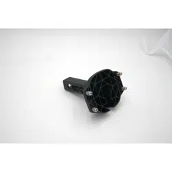
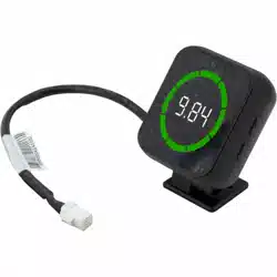
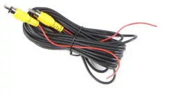
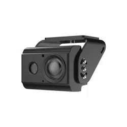
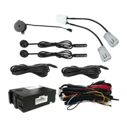
2. What's in the Box:
Electric drill
The diameter of
drill bit depends
on the sensors
LED extension cable
Nylon cable tie

www.PyleUSA.com 3
3. Wiring Diagram

www.PyleUSA.com4
Step 2: Sensor Installation
1. The ideal height to mount L & R sensors (Up 7°) is
about 60cm-70cm where the bumper is vertical to
the ground, CL & CR sensors (0°) is about 50cm-65cm.
Otherwise it may cause false alarm.
2. Keep the drilled hole clean after drilling to make
sure the proper size of installing sensors.
Keep sensors away from sponge, metal plate or
anything on the sensors surface, otherwise it may
cause false alarm.

www.PyleUSA.com 5
Function Introduction
Blind Spot Dectection Function
(Blind spot detection are both for XY-BSD500-4 and
XY-BSD500-2) System is activated when vehicle is
driving. Detection area is 5m long and 2.5m wide at
the rear side of vehicle. LED indicator turns ON if the
sensor detects another vehicle that comes near the
next lane.
If switching ON turn signal at the same side when
object is detected, LED indicator will ash and buzzer
will have 3 beeps.
Buzzer beeps three times once turn signal is
switched ON. If emergency button is switched ON,
both sides will turn ON.

www.PyleUSA.com6
Notes for instaIIation, test and tips
1. Installation
a. This product is applied to 12V battery vehicles,
please read manual carefully before installation.
b. To insure the length of cables t the vehicles
and convenience of routing cables, please
install control box at the left trunk.
c. Please connect cables as Wiring Diagram.
2. Test
a. If the system didn't work please check and insure
all cables connected properly.
b. If the system can’t detect the obstacles behind
the vehicle, please check sensors if properly in
upward position.
3. Tips
a. Please have a test rst on this system before
operating.
b. If dirt, rain or snow builds up on the sensor, the
sensor may not function properly.
If water droplets, snow or mud adhere to the
sensor and its components, rinse with water
and wipe with a dry cloth.
c. When reversing down a steep slope or driveway,
graveI, lawn and/or the road surface may cause
momentary detection signals due to the sensors
following the sloping angle of the vehicIe which
may cause false alarm.
d. Sensors can’t detect well on sponge, gIossy
sphere, spiky objects or very tiny obstacles.

www.PyleUSA.com 7
Features:
• Helps Driver Lane Changing Safely During Driving
• With the Aid of 58KHZ Ultrasonic Sensor
• Two Ultrasonic Sensors
• Two Blind Regions Monitor (or LED Light)
• With Buzzer and the Wire Harness, Perfect
Connection of Ultrasonic and Computer
• Integrates Blind Spot Detection and Reversing
Assistance
• High-speed Frequency Sensors for the Left-rear and
Right-rear of the Vehicle
• Buzzer Warning Indicators for the Right and Left Side
Technical Specs:
• BSD Function: Blind Spot Detecting System Function
• LCA Function: Lane Change Assist
• RCTA Function: Rear Cross Traffic Alert Function
• Type: Universal Blind Sport Monitoring System (BSM)
• Electricity Voltage: 12V
• Maximum Power: 5W (max)
• Working Temperature: -40°C~+85°C (-40°F~185°F)
• Storage Temperature: -40°C ~ +85°C (-40°F~185°F)
• Waterproof Level: IP67K
• Detection Range : 0m – 5m.
• Detection Range Accuracy: ±3cm
• Product Dimensions: 3.47'' x 2.36” x 11” -inches