
BSD Camera
Quick Start Guide
V1.0.0
I
Foreword
General
This manual introduces the structure, installation, and system configuration of BSD camera.
Safety Instructions
The following signal words might appear in the manual.
Signal Words Meaning
Indicates a potential risk which, if not avoided, could result
in property damage, data loss, lower performance, or
unpredictable result.
Provides additional
information as the emphasis and
supplement to the text.
Revision History
Version Revision Content Release Date
V1.0.0 First release. July 2022
Privacy Protection Notice
As the device user or data controller, you might collect the personal data of others such as their face,
fingerprints, and car plate number. You need to be in compliance with your local privacy protection
laws and regulations to protect the legitimate rights and interests of other people by implementing
measures which include but are not limited: Providing clear and visible identification to inform
people of the existence of the surveillance area and provide required contact information.
About the Manual
The manual is for reference only. Slight differences might be found between the manual and the
product.
We are not liable for losses incurred due to operating of the product in ways that are not in
compliance with the manual.
The manual will be updated according to the latest laws and regulations of related jurisdictions.
For detailed information, see the paper User Manual, use our CD-ROM, scan the QR code or visit
our official website. The manual is for reference only. Slight differences might be found between
the electronic version and the paper version.
All the designs and software are subject to change without prior written notice. Product
updates might result in some differences appearing between the actual product and the
manual. Please contact customer service for the latest program and supplementary
documentation.
There might be deviations in the description of the technical data, functions and operations, or
errors in the print. If there is any doubt or dispute, we reserve the right of final explanation.
Upgrade the reader software or try other mainstream reader software if the manual (in PDF
format) cannot be opened.
All trademarks, registered trademarks and the company names in the manual are the properties
of their respective owners.
Please visit our website, contact the supplier or customer service if any problems occur while
using the device.
If there is any uncertainty or controversy, we reserve the right of final explanation.
II
Important Safeguards and Warnings
Electrical Safety
All installation and operation shall conform to your local electrical safety codes.
Use power supply that meets SELV (extra low voltage), and supply power with rated voltage that
conforms to Limited Power Source in IEC60950-1. The rated voltage is DC 12V.
Check whether the power supply at the camera end meets the working voltage requirements of
the camera before operating the device (the material and length of the power supply cable will
affect the terminal voltage).
Prevent the power cable from being trampled or pressed, especially the cable and the junction
extruded from the device.
Environment
Transport, use and store the device within the range of allowed humidity and temperature.
Keep the device away from any liquid to avoid damage to the internal components.
Keep sound ventilation to avoid heat accumulation.
Heavy stress, violent vibration or water splash are not allowed during transportation, storage
and installation.
Pack the device with standard factory packaging or the equivalent material when transporting
the device.
The ground terminal (ground wire or grounding hole) of the device must be grounded to
improve device reliability.
It is recommended to select qualified video transmission cables to improve video quality.
Use standard components or accessories provided by manufacturer and make sure that the
device is installed and maintained by professional engineers.
Do not expose the surface of the image sensor to laser beam radiation in an environment where
a laser beam device is used.
Do not provide two or more power supply sources for the device unless otherwise specified. A
failure to follow this instruction might cause damage to the device.
III
Table of Contents
Foreword ............................................................................................................................................................ I
Important Safeguards and Warnings .............................................................................................................. II
1 Introduction ................................................................................................................................................... 1
General ........................................................................................................................................................................................... 1
Features ......................................................................................................................................................................................... 1
2 Structure ........................................................................................................................................................ 2
Unpack and check...................................................................................................................................................................... 2
Appearance .................................................................................................................................................................................. 2
Dimension ..................................................................................................................................................................................... 3
Port Definition ............................................................................................................................................................................. 3
3 Installation ..................................................................................................................................................... 4
Camera Installation ................................................................................................................................................................... 4
Cable Connection ...................................................................................................................................................................... 6
3.2.2 Installation Position ..................................................................................................................................................... 6
3.2.3 Cable Layout ................................................................................................................................................................... 8
Adjusting Camera Angle ....................................................................................................................................................... 10
4 System Configuration ................................................................................................................................. 12
Cybersecurity Recommendations ............................................................................................. 13

1
1 Introduction
General
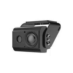
This camera adopts advanced circuit design with high sensitivity and features high image quality,
low distortion and low noise. It is suitable for monitoring system and image processing system. This
camera can be used for monitoring scenes with visual blind spots, such as freight vehicles,
engineering vehicles, school buses, etc.
Features
Applicable to the scene of monitoring vehicle blind area.
Ultra wide angle lens presents a wide video image.
Use high sensitivity image sensor and featuring high resolution, clear and delicate image.
3D noise reduction is adopted to improve low illumination brightness of the image and
effectively suppress noise interference.
HDCVI HD transmission technology is adopted to retain image details to the greatest extent.
Supports 9V DC to 16V DC power input.
Supports IP67 waterproof and IK08 explosion-proof grade.
2
2 Structure
The following figures are for reference only, and the actual product shall prevail.
For tools or accessories not mentioned in the box, please purchase as needed.
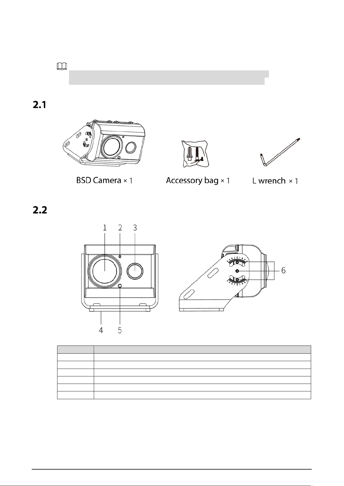
Unpack and check
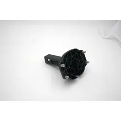
Appearance
Table 2-1 Appearance description
No.
Name
1
Lens
2
Microphone(reserved)
3
Fill light
4
Installing bracket
5
Light sensor
6
Adjusting screws
3
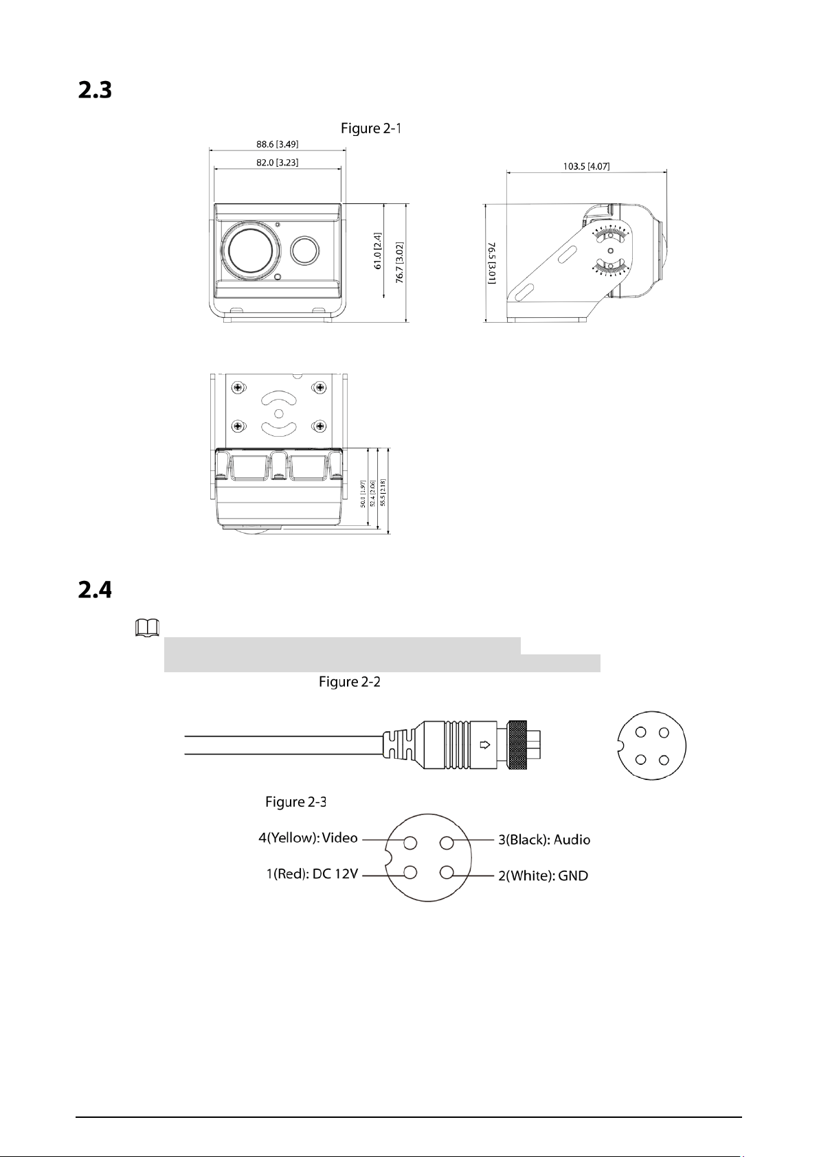
Dimension
Dimensions
Port Definition
The port of the BSD camera is a four-pin aviation connector.
Ports of different device be different, and the actual product shall prevail.
Aviation connector
Pin assignment of aviation connector
4
3 Installation
The BSD camera is mainly installed outside the left and right doors of the driver’s cab, and can also
be installed on the rear-view mirror pole, front and rear of the vehicle.
The installation surface is required panel sustain at least 3 times the weight of the device.
Do not tear off the anti-static adsorption film on the lens surface before the installation and
commissioning is completed, so as to prevent the lens from being damaged during the
installation process; After tearing off the adsorption film, do not touch the lens.
This part takes some models as the example, and the actual model shall prevail.
Camera Installation
There are two installation methods: Side mounting and pole mounting.
The pole mounting needs hoop bracket (support customization). This document focuses on the side
mounting.
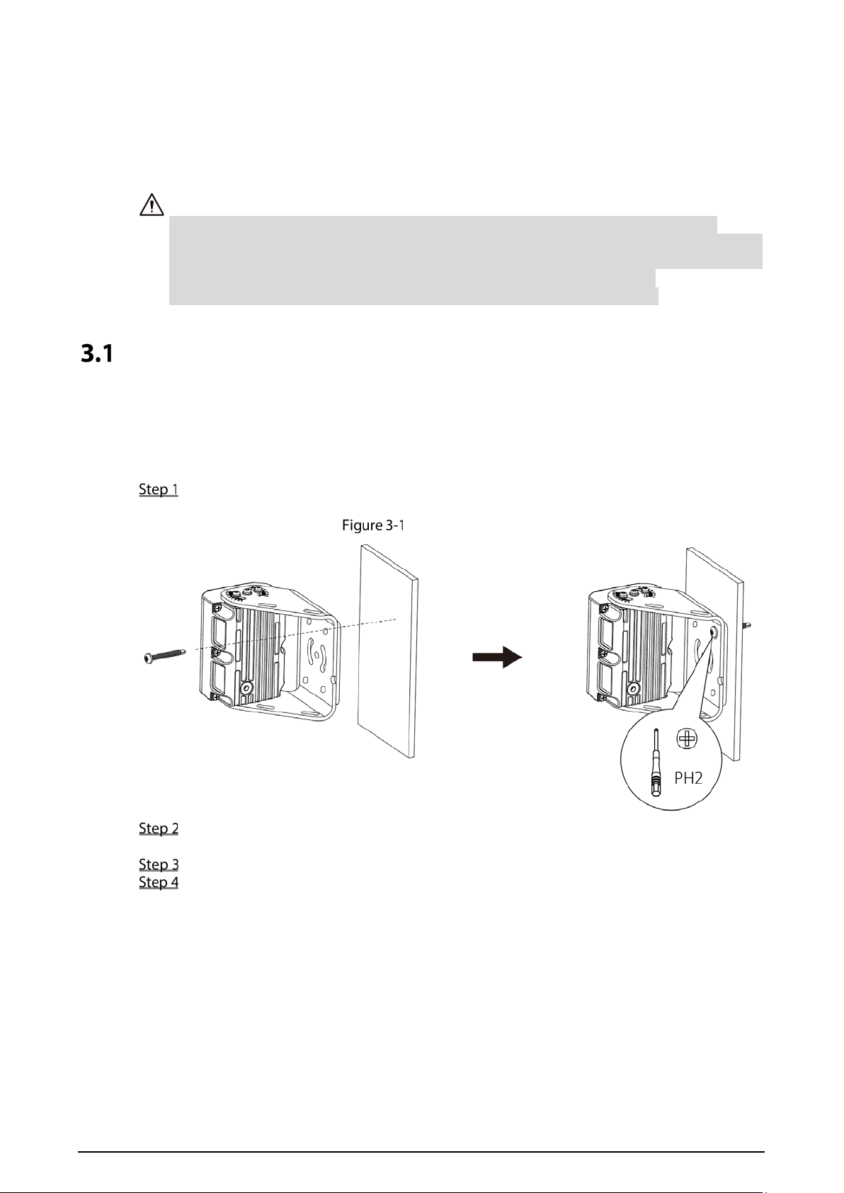
Side mounting
Stick the bracket of the camera close to the mounting surface, and use a cross screwdriver to
fix a ST4.2×30 screw into any mounting hole on the bracket.
Side mounting
Use an extension cable to connect the BSD camera and the mobile video recorder. See
"3.2.3Cable Layout" for details.
Preview the video image in real time on the local display screen.
Adjust the camera bracket and body according to the video to ensure that the picture taken
by the camera covers the blind area. See "3.3Adjusting Camera Angle" for the division of
blind area.
1) Adjusting bracket
Turn the bracket according to the video, adjust it to the best angle, and screw the
remaining three self-tapping screws into the mounting surface along the mounting
hole of the bracket.
2) Adjusting camera
Use an L-shaped box wrench to loosen the six fixing screws at the lens adjustment on
both sides of the camera.
5
Loosen the adjusting screws
Adjusting camera
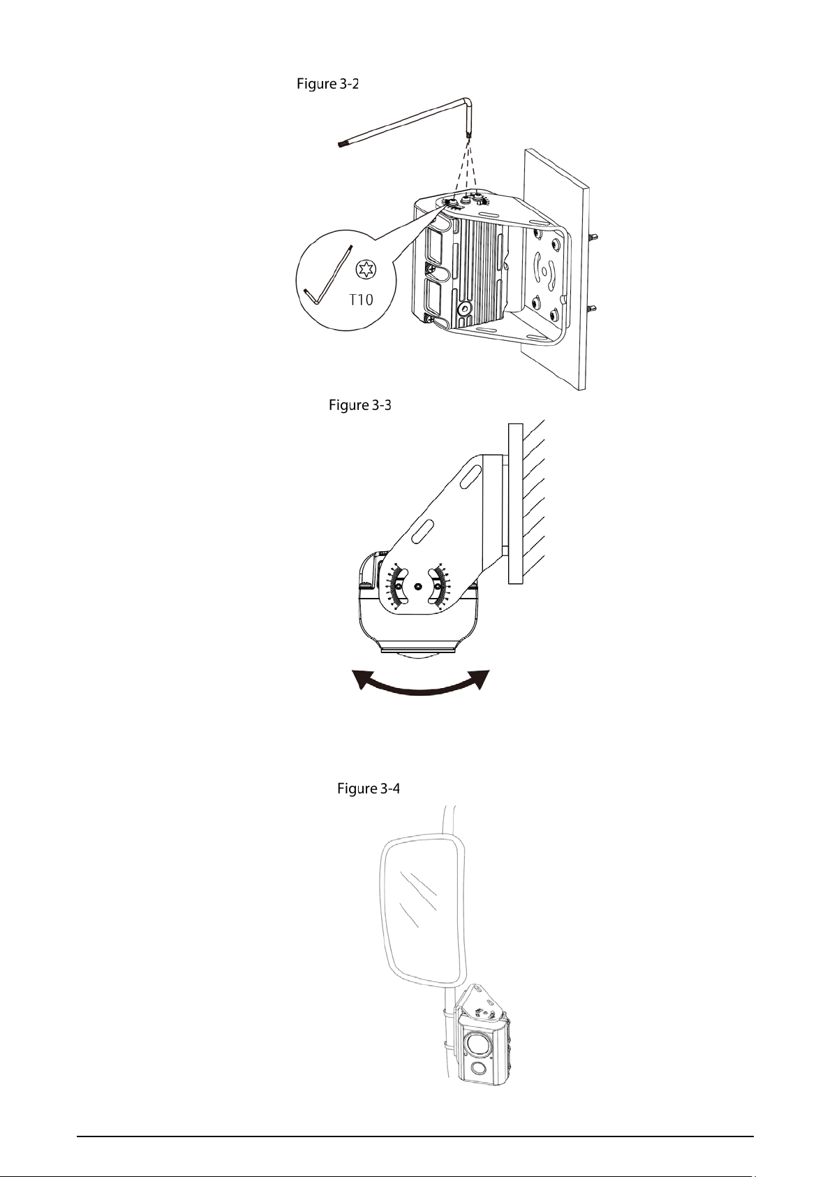
Pole mounting
The pole mounting is applicable to the scene where the BSD camera is installed on the rear-view
mirror pole.
Pole mounting
6
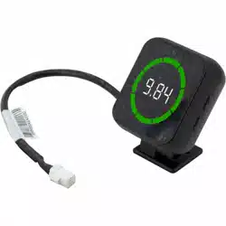
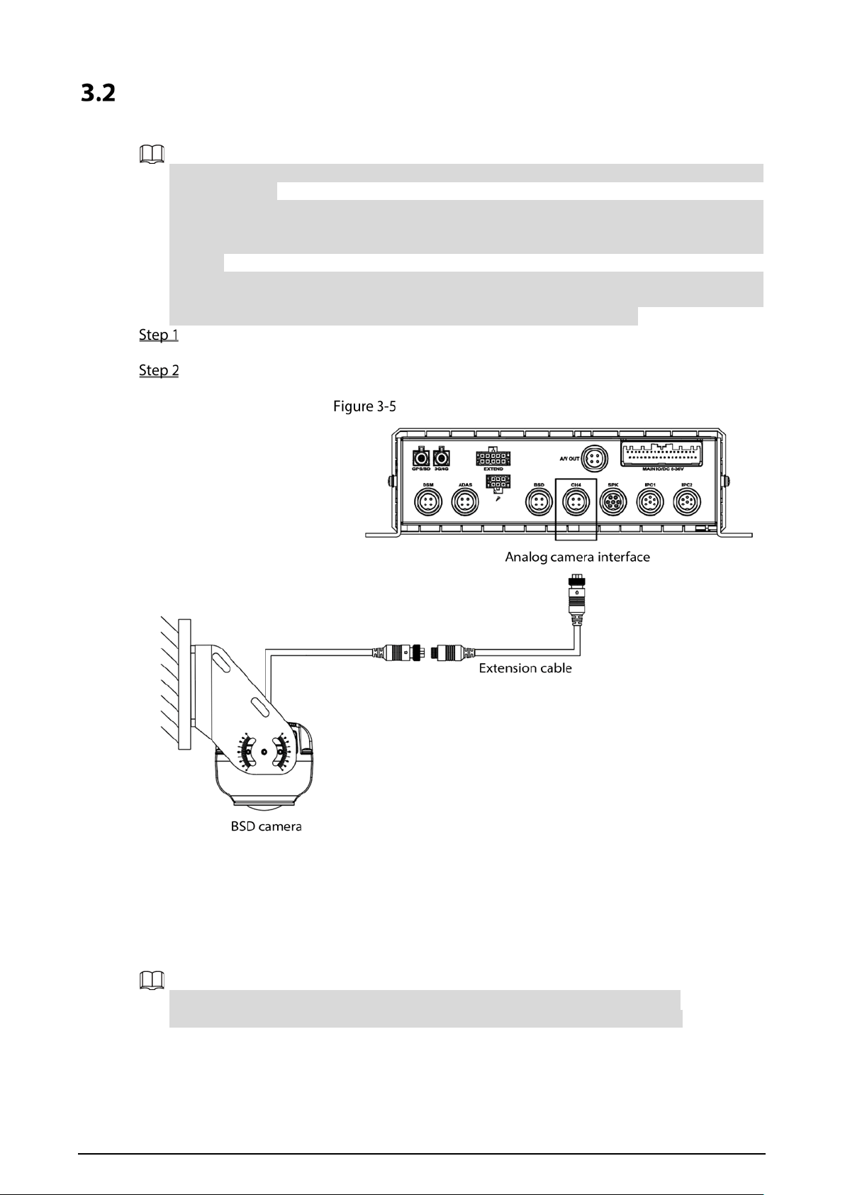
Cable Connection
Connect the BSD camera to the mobile video recorder to realize real-time monitoring.
The mobile video recorder here takes model 5100 as an example. Please refer to the actual
device for details.
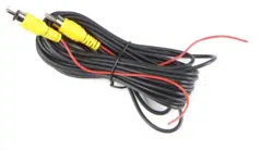
The device is not equipped with extension cable by default, purchased it as needed. The two
ends of the extension line are M12 four-core aviation port, one end is connected with the BSD
camera, and the other end is connected with the analog camera interface of the mobile video
recorder.
During installation, the interface is exposed outside the vehicle, and there is a risk of water
ingress, which affects the stability of device operation. Therefore, it is recommended to
purchase waterproof materials to prevent water from entering the interface.
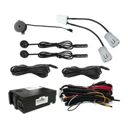
Use an extension cable to connect the cable interface of the BSD camera to the analog
camera interface of the mobile video recorder, as shown in Figure 3-6.
Tighten the nuts of the extension cable and the cable interface of the BSD camera.
Connections are completed.
Cable Connection
3.2.2 Installation Position
The BSD camera can be installed on the outside of the driver’s cab, the front of the car, the rear of the
car or the rear-view mirror. The part takes the truck as an example to introduce the installation
position. Please refer to the corresponding construction scheme for the specific model.
When installing the BSD camera, the recommended installation height is ≥ 2.5m.
The installation surface shall be as flat as possible and perpendicular to the ground.
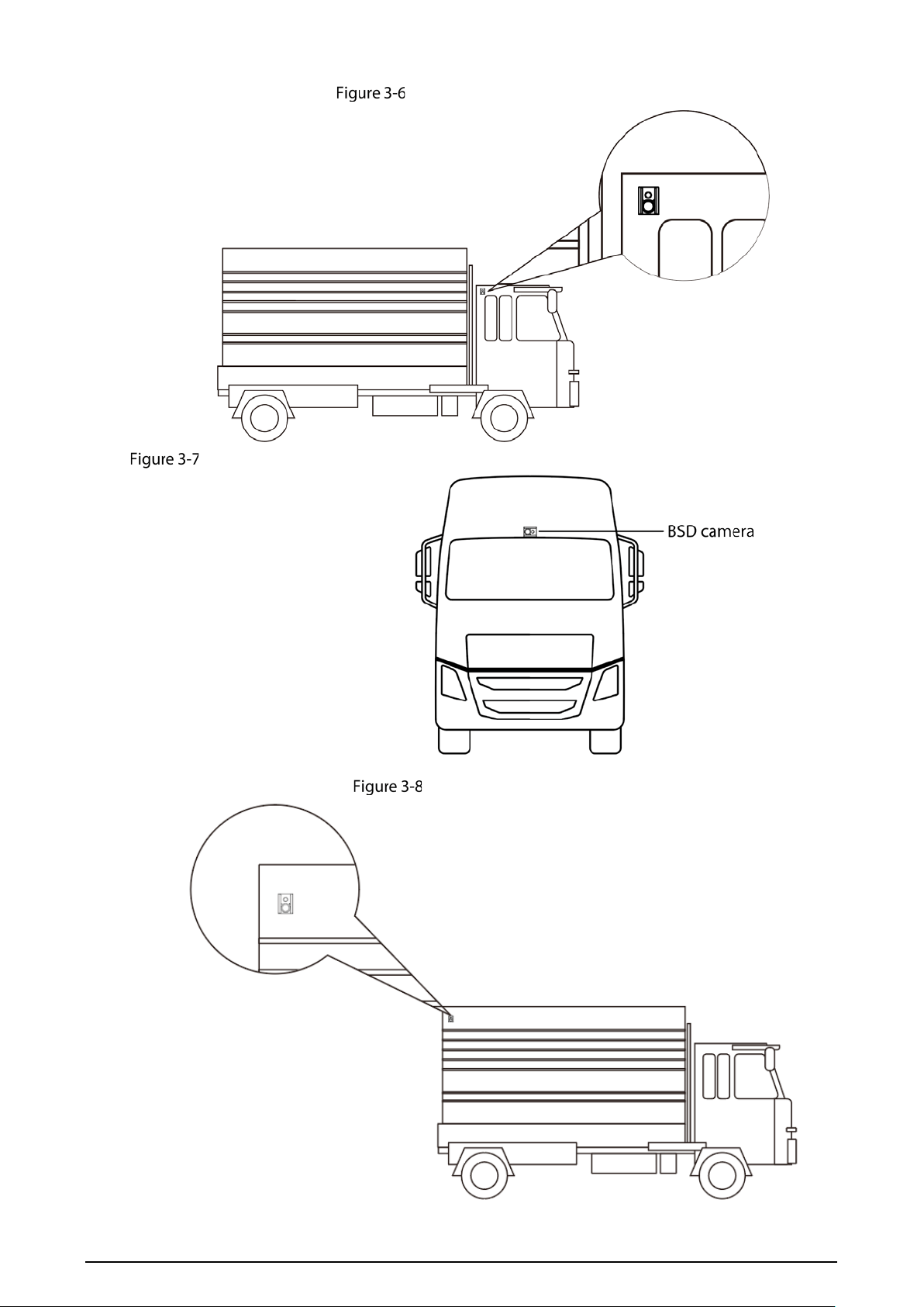
7
Outside of the driver’s cab
On the front of the car
On the rear of the car
8
On the rear-view mirror
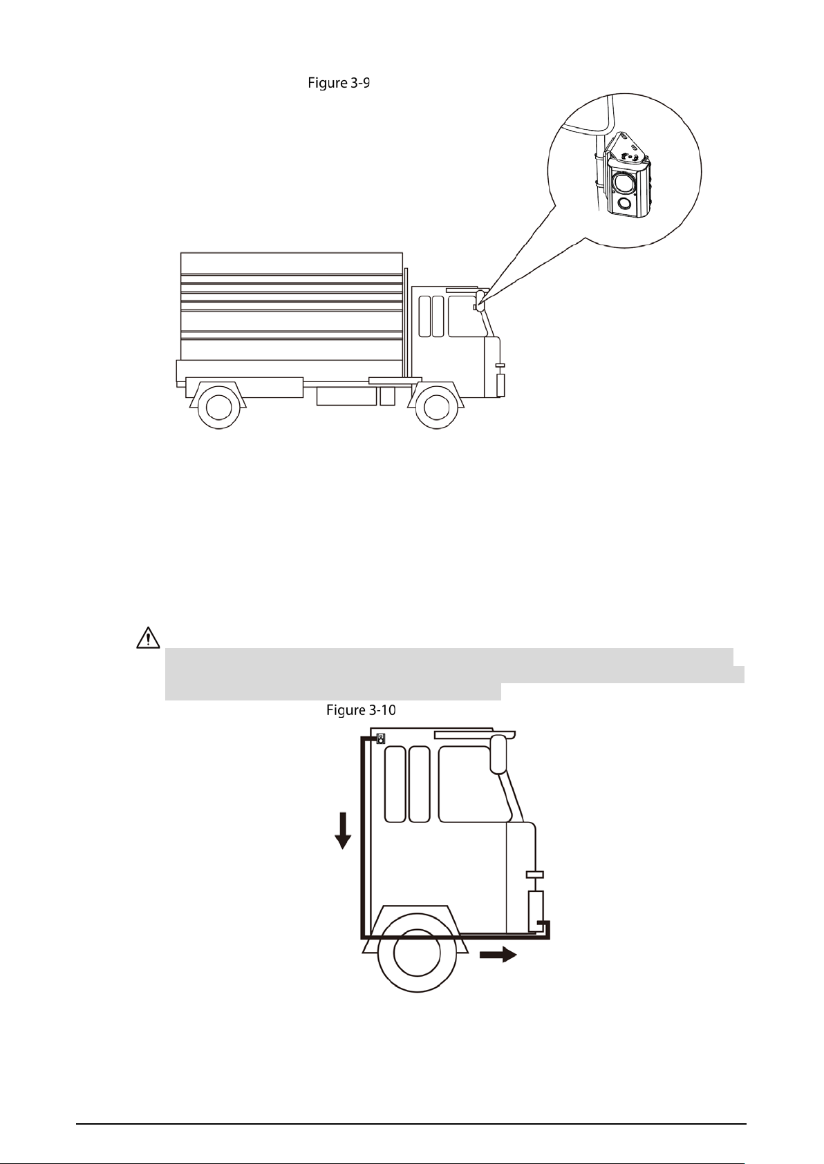
3.2.3 Cable Layout
Different cars have different cable layout methods. Here are four main installation methods. Please
refer to the actual situation.
Outside of the driver’s cab
The BSD needs to be connected with an extension cable, which is threaded through the back of the
car head, runs through the bottom of the driver’s cab, and then led into the driver’s cab through the
junction box hole in the front of the car head to connect the mobile video recorder. See Figure 3-10.
Cables shall be fixed with ties throughout the whole process to avoid hanging cables in the air.
The extension line at the bottom of the cab should be fixed on the front of the vehicle instead of
the frame because the vehicle head may be overturned.
Cable Layout (1)
9
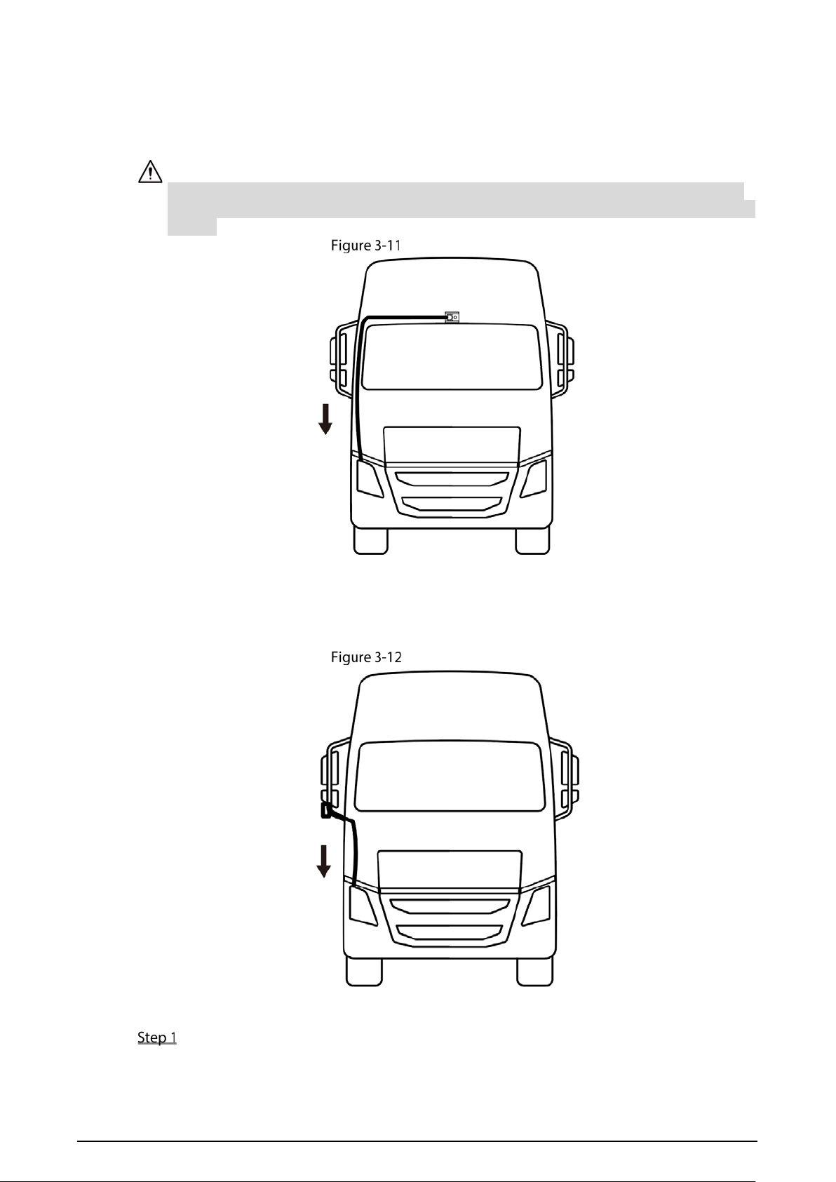
On the front of the car
Route the extension cable above the front windshield, extend it along the outside of the left and
right windscreens to the junction box in front of the vehicle head, introduce the extension line into
the cab through the hole of the junction box, and connect the mobile video recorder.
Cables shall be fixed with ties throughout the whole process to avoid hanging cables in the air.
The extension cable should not block the windshield, so as not to interfere with the driver's line
of sight.
Cable Layout (2)
On the rear-view mirror
The extension cable is routed along the rear-view mirror rod, and then extends along the body to the
junction box in the front of the vehicle head. The extension cable is introduced into the cab through
the hole of the junction box and connected to the mobile video recorder.
Cable Layout (3)
On the rear of the car
Route the camera extension cable under the vehicle and route it along the frame, as shown
in Figure 3-13. Fix the cable with ties or iron wires to prevent the cable from moving.

10
After the wiring of the frame part is completed, the extension cable is introduced into the
cab through the junction box hole in the front of the car head, and the mobile video
recorder is connected.
The cable shall be fixed through the frame of the car itself, and shall not interfere with the
container, so as to avoid the lifting of the container involving the cable.
After the wiring is completed, the cable should be tightened, and the excess part should be left
in the cab.
Cable Layout (4)
Adjusting Camera Angle
When installing the BSD camera, the blind area of vision should be adjusted to ensure that the video
image presented by the blind area camera covers the blind area of driver’s vision.
When the BSD camera is installed on the outside of driver’s ab, the rear of the vehicle or the
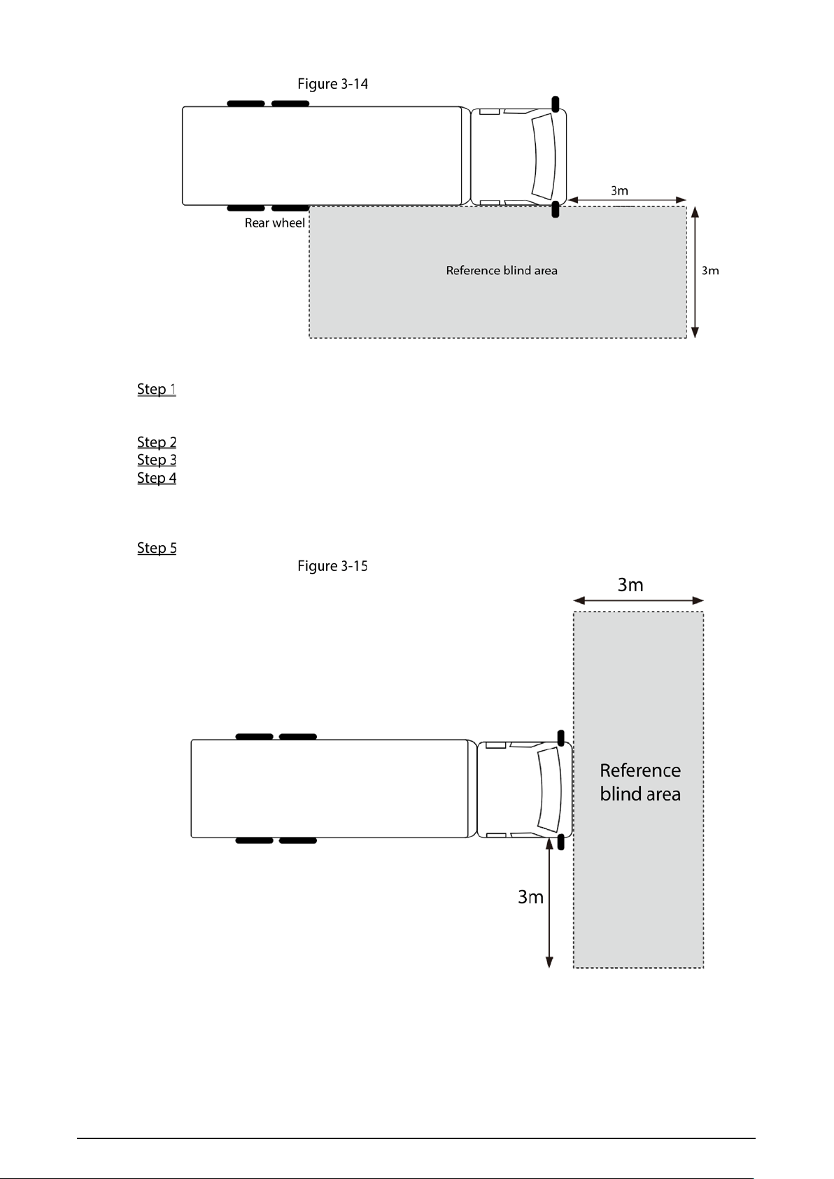
rear-view mirror, adjust the camera angle according to the following steps.
According to the requirements of Figure 3-14, place references at the four corners of the
reference area in the blind area.
Connect the camera to the mobile video recorder.
Preview the video image in real time on the local display screen.
Refer to "3.1Camera Installation", loosen the self-tapping screws and lens adjusting screws,
rotate the bracket and body, and observe the image until it covers the reference objects
around the blind area rectangle, and the body accounts for about 1/4 of the image.
Tighten all the screws on the camera, and the blind area vision adjustment is completed.
11
Adjusting camera angle (1)
When the BSD camera is installed on the front of the vehicle head, adjust the camera angle
according to the following steps.
According to the requirements of Figure 3-15, place a reference object on the ground 3
meters away from the front of the vehicle for reference when adjusting the angle of view in
the blind area.
Connect the camera to the mobile video recorder.
Preview the video image in real time on the local display screen.
Refer to "3.1Camera Installation", loosen the self-tapping screw and lens adjusting screw,
rotate the bracket and body, and observe the picture until the video picture covers the
reference object in front of the vehicle head, and the bottom of the picture is close to the
vehicle head boundary.
Tighten all the screws on the camera, and the blind area vision adjustment is completed.
Adjusting camera angle (2)

12
4 System Configuration
After the installation and wiring are completed, the video parameters of the BSD camera need to be
configured on the local and web interfaces of the mobile video recorder. The parameter
configuration of the BSD camera mainly includes the configuration of video channel, detection
direction, alarm output, detection speed, blind area division, etc.
For details, see the user’s manual of the mobile video recorder MDJ5100.

13
Cybersecurity Recommendations
Mandatory actions to be taken for basic device network security:
1. Use Strong Passwords
Please refer to the following suggestions to set passwords:
The length should not be less than 8 characters.
Include at least two types of characters; character types include upper and lower case
letters, numbers and symbols.
Do not contain the account name or the account name in reverse order.
Do not use continuous characters, such as 123, abc, etc.
Do not use overlapped characters, such as 111, aaa, etc.
2. Update Firmware and Client Software in Time
According to the standard procedure in Tech-industry, we recommend to keep your device
(such as NVR, DVR, IP camera, etc.) firmware up-to-date to ensure the system is equipped
with the latest security patches and fixes. When the device is connected to the public
network, it is recommended to enable the “auto-check for updates” function to obtain
timely information of firmware updates released by the manufacturer.
We suggest that you download and use the latest version of client software.
"Nice to have" recommendations to improve your device network security:
1. Physical Protection
We suggest that you perform physical protection to device, especially storage devices. For
example, place the device in a special computer room and cabinet, and implement well-done
access control permission and key management to prevent unauthorized personnel from
carrying out physical contacts such as damaging hardware, unauthorized connection of
removable device (such as USB flash disk, serial port), etc.
2. Change Passwords Regularly
We suggest that you change passwords regularly to reduce the risk of being guessed or cracked.
3. Set and Update Passwords Reset Information Timely
The device supports password reset function. Please set up related information for password
reset in time, including the end user’s mailbox and password protection questions. If the
information changes, please modify it in time. When setting password protection questions, it is
suggested not to use those that can be easily guessed.
4. Enable Account Lock
The account lock feature is enabled by default, and we recommend you to keep it on to
guarantee the account security. If an attacker attempts to log in with the wrong password
several times, the corresponding account and the source IP address will be locked.
5. Change Default HTTP and Other Service Ports
We suggest you to change default HTTP and other service ports into any set of numbers
between 1024–65535, reducing the risk of outsiders being able to guess which ports you are
using.
6. Enable HTTPS
We suggest you to enable HTTPS, so that you visit Web service through a secure communication
channel.
7. MAC Address Binding
We recommend you to bind the IP and MAC address of the gateway to the device, thus reducing
the risk of ARP spoofing.
8. Assign Accounts and Privileges Reasonably
According to business and management requirements, reasonably add users and assign a
minimum set of permissions to them.
9. Disable Unnecessary Services and Choose Secure Modes
If not needed, it is recommended to turn off some services such as SNMP, SMTP, UPnP, etc., to
reduce risks.
If necessary, it is highly recommended that you use safe modes, including but not limited to the
following services:

14
SNMP: Choose SNMP v3, and set up strong encryption passwords and authentication
passwords.
SMTP: Choose TLS to access mailbox server.
FTP: Choose SFTP, and set up strong passwords.
AP hotspot: Choose WPA2-PSK encryption mode, and set up strong passwords.
10. Audio and Video Encrypted Transmission
If your audio and video data contents are very important or sensitive, we recommend that you
use encrypted transmission function, to reduce the risk of audio and video data being stolen
during transmission.
Reminder: encrypted transmission will cause some loss in transmission efficiency.
11. Secure Auditing
Check online users: we suggest that you check online users regularly to see if the device is
logged in without authorization.
Check device log: By viewing the logs, you can know the IP addresses that were used to log
in to your devices and their key operations.
12. Network Log
Due to the limited storage capacity of the device, the stored log is limited. If you need to save
the log for a long time, it is recommended that you enable the network log function to ensure
that the critical logs are synchronized to the network log server for tracing.
13. Construct a Safe Network Environment
In order to better ensure the safety of device and reduce potential cyber risks, we recommend:
Disable the port mapping function of the router to avoid direct access to the intranet
devices from external network.
The network should be partitioned and isolated according to the actual network needs. If
there are no communication requirements between two sub networks, it is suggested to
use VLAN, network GAP and other technologies to partition the network, so as to achieve
the network isolation effect.
Establish the 802.1x access authentication system to reduce the risk of unauthorized access
to private networks.
Enable IP/MAC address filtering function to limit the range of hosts allowed to access the
device.