Loading ...
Loading ...
Loading ...
English■
9
Installation Tips
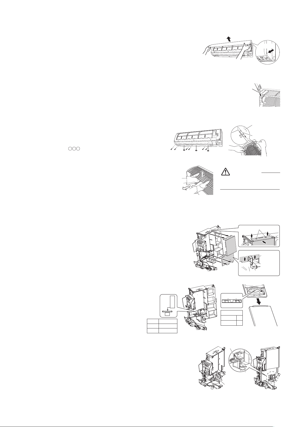
1. Removing and installing the front panel
• Removal method
1) Grip the panel tabs on each side of the front panel and open.
2) Slide the front panel to either the left or right and pull it toward you to
disengage one of the front panel shafts.
3) Disengage the front panel shaft on the other side in the same manner.
4) After disengaging both front panel shafts, pull the front panel toward yourself and remove it.
• Installation method
Align the front panel shaft of the front panel with the grooves of grille, and push
all the way in, then close slowly.
Push the center of the lower panel surface firmly to engage the tabs.
2. Removing and installing the front grille
• Removal method
1) Remove the front panel and air filters.
2) Remove 6 screws from the front grille.
3) Remove 3 front grille fixtures from the front grille.
4)
In front of the mark on the front grille, there are 4 upper
hooks. Lightly pull the front grille toward you with one hand, and
push down on the hooks with the fingers of your other hand.
When there is insufficient work space because the unit
is close to ceiling
Place both hands under the center of the front grille,
and while pushing up, pull it toward you.
• Installation method
1) Install the front grille and firmly engage the upper hooks
(4 locations).
2) Install 6 screws of the front grille.
3) Install 3 front grille fixtures of the front grille.
4) Install the air filters and then mount the front panel.
3. How to set the different addresses
When 2 indoor units are installed in one room, the 2 wireless remote controllers can
be set for different addresses. Change the address setting of one of the 2 units.
When cutting the jumper, be careful not to damage any of the surrounding parts.
1) Remove the front grille. (6 screws, 3 front grille fixtures)
2) Remove the metal plate electrical wiring box cover. (4 tabs)
(See Fig.1)
3) Cut the address jumper (JA) on the printed circuit board.
(See Fig.2)
4)
Cut the address jumper (J4) in the remote controller.
(See
Fig.3
)
• Do not cut jumper (J8). (Jumper (J8) is cut to switch
over the system to cooling only.)
5) Replace the metal electrical wiring box cover.
6) Replace the front grille.
4. When connecting to an HA system
1) Remove the front grille. (6 screws, 3 front grille fixtures)
2) Remove the metal plate electrical wiring box cover. (4 tabs) (See Fig.1)
3) Attach the connection cord to the S21 connector and pull the harness
out through the notched part in the figure. (See Fig.4)
4) Replace the electrical wiring box cover as it was, and pull the harness
around, as shown in the figure. (See Fig.5)
5) Replace the front grille.
Panel tab
Push the front panel
shaft of the front panel
into the groove.
Front panel shaft
Push
down.
Upper hook
mark area
(4 locations)
Be sure to wear protection
gloves.
CAUTION
1) Push up.
2) Pull toward
you.
Slide
Metal plate
electrical
wiring box
cover
Main body
Pull
Pull
SlideSlide
Ta b
Fig.1
1
2
Jumper
(J8) (J4)
ADDRESS
EXIST
CUT
Fig.2 Fig.3
ADDRESS
JA
ADDRESS
JA
EXIST
CUT 2
1
Fig.4 Fig.5
HA connector
(S21)
HA connector
(S21)
Lay the HA cord as
shown in the figure.
Loading ...
Loading ...